Article

Ductile Moment-Resisting Timber Connections: A Review

by
Arthur S. Rebouças
,
Zabih Mehdipour
,
Jorge M. Branco
* and
Paulo B. Lourenço
Department of Civil Engineering, University of Minho, ISISE, 4800-058 Guimarães, Portugal
*
Author to whom correspondence should be addressed.
Buildings 2022, 12(2), 240; https://doi.org/10.3390/buildings12020240
Submission received: 23 December 2021 / Revised: 9 February 2022 / Accepted: 17 February 2022 / Published: 19 February 2022
(This article belongs to the Special Issue Seismic Design and Performance of Timber Structures)

Abstract

:
In the last two decades, high-rise timber buildings have been built using the glulam truss system, even with limited openings. Moment-resisting timber frames (MRTF) with semi-rigid beam-to-column connections can be an architecture-friendly way to provide a load-carrying system to vertical and horizontal loads for timber buildings. In these structures, connections of adequate ductility are crucial to ensure robustness and energy dissipation. This paper presents a review of the main types of timber beam–column moment connections with improved ductility and proposes to carry out a ductility assessment of these connections based on the most relevant ductility factors. Joints have a significant influence on the global performance of MRTF, and the application of ductile connections have improved the mechanical parameters of the timber frame. The reinforced bolted slotted-in steel plate and glued-in rods connections have similar mechanical performance, with high rotation capacity and good ultimate moment, but exhibited different failure modes under cyclic loading. The connections were classified within ductility classes. In general, the glued-in steel rods presented better results because of the high influence of steel profiles in the connection yielding. Despite the excellent mechanical behavior, the reinforced bolted slotted-in steel plate connections presented medium ductility values.

1. Introduction

Timber is a natural and renewable resource that can have high level of prefabrication; it is quick to assemble and presents a high strength-to-mass ratio favorable for building in seismic areas. Those are the main reasons that motivated the interest in multi-story timber structures. In the last two decades, high-rise timber buildings have been built using the glulam truss structural system, where the massive diagonal elements are connected by multiple slotted-in steel plates and dowel joints to ensure structural robustness [1]. However, this system restrains several architectural possibilities—namely, it limits large openings. On the other hand, moment-resisting timber frames (MRTF) with semi-rigid beam-to-column connections can be a convenient and architecture-friendly way to provide a load-carrying system to vertical and horizontal loads for timber buildings [2].
As MRTF allows for buildings without shear walls or x-bracing, the redistribution of internal forces via connections of adequate ductility is crucial for ensuring structural robustness. A main requirement for robust structures is the claim that no sudden failure occurs at any time, while the ductile connections must announce the failure by presenting large deformations, rotations, or cracks. In these statically indeterminate structures, a plastic design of connections in order to obtain a ductile behavior is essential and can lead to material savings and more safety reserve.
Furthermore, as for robustness analysis, in seismic design, the main objective is to guarantee that the structure survives an earthquake without extensive damage. The Eurocode 8 [3] describes the relevance of ductility for the structural behavior under seismic actions, emphasizing that dissipative zones shall be located in connections, whereas the timber members themselves shall be regarded as behaving elastically. Dissipative structures are able to dissipate energy by means of ductile hysteretic behavior, and in timber structural components connected by bolts or bars, the energy is dissipated by plastic deformation of both timber and metal connectors under reverse-cyclic loading [4].
Despite their relevance, the ductile behavior of MRTFs connections have not been discussed and explored in-depth. This paper presents a review of the main types of timber beam–column moment connections with improved ductility to study more about its mechanical behavior and to identify gaps in some aspects that have not been studied. The main objective of this work is to evaluate the ductility of the selected connections based on the most relevant recommendations provided by different standards and guidelines. It is intended to provide a detailed comparison between the most common types of semi-rigid timber joints with improved ductility. Therefore, geometric parameters are presented, and the connections behavior under cyclic and monotonic load are described, identifying the failure modes obtained. This study of the existing knowledge is essential for evaluating the potential associated with semi-rigid timber joints within frame structural systems, and it allows identification of the research gaps for their implementation in practice, through design guidelines and recommendations.

2. Ductility in Timber Joints

The definition of ductility remains an issue for designers due to the large number of formulae that lead to different results. According to [5], ductility is the ability of a structure to undergo large amplitude cyclic deformations in the inelastic range without a substantial reduction in strength. In timber structures, ductility is mainly achieved through the connections. Eurocode 8 [3] imposes that elements must behave linearly and that all non-linear behavior must be concentrated on the joints. The Swiss code for timber structures, SIA 265 [6], and the European standard EN 12512 [7] defined ductility as the ability of the joint to undergo a large amplitude slip in the plastic range without a substantial reduction in strength. Thus, according to those codes, ductility is measured by a factor between the ultimate deformation and the deformation at yielding. On the other hand, Eurocode 8 [3] defines static ductility as a ratio between the ultimate deformation and the deformation at the end of elastic behavior evaluated in quasi-static cyclic tests. Ref. [8] emphasizes that the method specified in Eurocode 8 [3] is adequate for evaluating the ductility of highly deformable joints or structures. Although much research has used these definitions to measure ductility, there is not a universally accepted definition by the research community. To enable a more accurate assessment of the ductility, Ref. [9] presented 12 different definitions (Equations (1)–(12)). The Equations (1)–(7) are relative definitions, while Equations (8)–(12) are absolute definitions of ductility. Definition Equation (2) is cited in both EN 12512 [7] and in the Swiss timber code for timber structures SIA265 [6].
μ = Δ F m a x / Δ F y
μ = Δ F u / Δ F y
μ = Δ F u / Δ F m a x
μ = ( Δ F m a x Δ F y ) / Δ F m a x
μ = ( Δ F u Δ F y ) / Δ F u
μ = K e / F 1 Δ F m a x   where   F 1 = m a x F ( 0 Δ   5   mm )
μ = K e / F 1 Δ F u   where   F 1 = m a x F ( 0 Δ   5   mm )
μ = Δ F m a x Δ F y   ( mm )
μ = Δ F u Δ F y   ( mm )
μ = Δ F u Δ F m a x   ( mm )
μ = Δ = 0 Δ = Δ F m a x f ( F , Δ ) d Δ   ( Nmm )
μ = Δ = 0 Δ = Δ F u f ( F , Δ ) d Δ   ( Nmm )
where Ke is the elastic stiffness, Fy the yield capacity and ΔFy the corresponding yield displacement, Fmax the peak capacity and ΔFmax the respective displacement, Fu the ultimate capacity at point of failure (or Fu = 0.8 Fmax, whichever occurs first) and ΔFu being the corresponding ultimate displacement.
Ref. [10] studied the validity of these propositions based on four criteria: (i) A connection will not be considered ductile if maximum displacement or rotation values are reached with a high loss of resistance; (ii) Definitions that are directly related to the calculation of energy dissipation by the area under the curve are impractical; (iii) The definitions must consider the post-peak behavior to be able to properly compose the connection displacement amplification ability; and, (iv) when the definition produces vastly different ductilities for variations in initial stiffness while the load–displacement curves look very similar and achieve the same final displacement, it is not applicable.
As consequence, according to [10], the most suitable ductility definition is the one that relates the difference between displacement at failure (ΔFu) and displacement at yielding (ΔFy):
( Δ F u Δ F y ) / Δ F u
The process of quantifying ductility factors depends on the yielding deformation point, which is defined as the load at which an assembly begins to deform plastically. In theory, this point is detectable under monotonic loading tests; however, most timber connections present a nonlinear load–displacement relationship and a transition between elastic and plastic behavior that is not clear. Therefore, in practice, there are several different definitions available for determining the yielding point, leading to different results. Ref. [11] summarized the commonly used methods and highlighted that the use of different methods can result in values with a difference of up to 80%. For the comparison presented in this paper, only the method proposed by EN 12512 [7] was applied.
A classification system for timber joints was proposed by [12], through which connections and components can be classified in four categories (Table 1) associated with a specific failure mode. This proposal has the advantage of using the ductility factor (u) suggested by EN 12512 [7] and used in the present work.
It is important to note that the ductility factor can be used for the entire structure or just for a part of it, such as a subsystem or a connection. In accordance with Eurocode 8 [3], timber buildings shall be assigned to one of the three ductility classes—low (L), medium (M), or high (H), as given in Table 2—depending on their ductile behavior and energy dissipation capacity under seismic actions. To each ductility class, different values of behavior factors (q) are admissible.
To be classified in ductility class M, the dissipative zones of a structure (joints are dissipative zones) shall be able to deform plastically for at least three fully reversed cycles at a ductility factor of 4. Additionally, to be classified as H, the dissipative zones must have a ductility factor of 6, without more than a 20% reduction in their resistance.

3. Performance of Moment-Resisting Joints in Timber Frames

Refs. [13,14] developed studies to investigate the lateral resistance and ductility of portal frames under cyclic loading. These studies expected that portal frames could sustain not only vertical loads but also lateral loads due to wind or/and earthquake loads. The experimental results have indicated that the connections could present a good mechanical performance—in particular, when they are reinforced. Ref. [15] performed an analytical study of timber structures with a moment-resisting joint made up of steel plates, bolts, and steel cotters. The analysis model used for earthquake response analysis is shown in Figure 1, which modeled a three-story timber frame house. The analysis model presented a good agreement with the experimental result, and the structural system clearly showed energy absorption characteristics for earthquake excitation.
Ref. [16] investigated the seismic performance of a timber frame with three-dimensional (3D) rigid connections made with inclined self-tapping screws and beech hardwood block at the top and bottom of the beam. To assess the seismic performance, a full-scale one-story frame using these developed connections was tested. The structure showed no significant damage up to a peak ground acceleration of 1.25 g. Failure of the frame occurred with a peak ground acceleration of 1.5 g. The beam-to-column connection did not present enough ductility during the extreme event simulation. Comparing the maximum rotations in the beam-to-column testing, the rotation that was measured in the frames was 0.02° during the first seismic test, 0.72° in the second test, and 1.41° in the third seismic test. Ref. [16] emphasized that comparisons between the frame testing and the connection tested had to be made carefully because the measurement of these rotations was with slight uncertainty due to variations in the pivot point (center point of rotation).
Ref. [17] tested nine full-scale one-story timber post and beam construction specimens: three unreinforced and six failed frames tested first by [18] using Fiber Reinforced Polymers (FRP) (FR series) and self-tapping screws (SR series) as reinforcement. The experiments were executed under cyclic loading. All of the specimens had span–depth ratio of 1.5, the column sections were 280 mm × 230 mm, the beam sections were 280 mm × 180 mm, and the brace sections were 135 mm × 105 mm. The unreinforced bottom column and the beam-to-column joints presented premature splitting when the lateral displacement of the frame reached 50 mm. Both reinforcement methods performed well in controlling the crack development at the joint connection and increasing load bearing capacity of the simple frame structure. The performance of the connection alone was not studied, but the reinforced connections improved the mechanical parameters of the frame. The ultimate load increased by 24%, and the horizontal displacement was reduced by 7%.
Ref. [19] developed a structural analysis in a semi-rigid timber portal frame and studied the moment resistance of its connections by experimental tests (monotonic and cyclic) performed on three full-scale timber portal frames and five bolted timber connections. All of the frame specimens had a span of 4110 mm and a height of 2740 mm (span–depth ratio of 1.5). The column sections were 280 mm × 230 mm, and the beam sections were 280 mm × 180 mm. The joint connections were bolted glulam connections slotted in steel plates. During the test, the moment-rotation curves did not present a significant load drop, but a simple frame specimen showed premature splitting around the bolts on the tension side of the beam member at the rotation of approximately 6°. The main experimental results—namely, elastic stiffness (ke) and peak load (Ppeak)—are summarized in Table 3.
According to [19], the test results did not have good agreement with the theoretical calculations. In experimental tests, the rotation centers of the connections varied (due to the members’ compression and wood splitting) during the loading process, while in the mechanical model, the connections were simulated by nonlinear spring elements with fixed rotation centers.
Ref. [20] analyzed the seismic performance of timber frames based on a calibrated model. A full-scale frame structure with a 1.5 span-to-height ratio was tested under cyclic loading. The moment-resisting connection was bolted with slotted steel plates. The uplift of the column was the main reason for the deformation of the timber frame, and the bolted joints had a significant influence on the global performance of the timber frame. After several loading cycles, plastic deformation occurred at the joint, the damage being concentrated on the beam–column and column–base joints. The frame presented large lateral displacements and localized deformations on the beam–column and column–base joints, probably due to the absence of bracing or infill of another material (Figure 2).
Ref. [21] evaluated the feasibility and the limitations of moment-resisting timber frames under service load according to current regulations. The main parameters that influence the overall serviceability performance of the of this kind of structure are the rotational stiffness of beam-to-column and column-to-foundation connections, story number and height, number and length of bays, column cross-section dimensions, and spacing between frames.
In all the studies that experimentally tested timber frames, connections have been demonstrated to be of paramount importance because of their potential to control the ductility and the maximum deformation of these structures. In general, ductile connections have improved the mechanical parameters of the frame, increasing the ultimate load and reducing horizontal displacements. Past studies also indicate that timber frames equipped with reinforced bolted timber connections can carry more bending moment and can better resist lateral load when compared with unreinforced ones. It happens because the reinforcements could prevent premature splitting, increasing the ultimate moment and the rotation capacity of the connection.

4. Moment-Resisting Joints in Timber Structures

In decades of 1970 and 1980, the first moment-resistant joints were designed and tested using nails transversely to the timber and plates at both sides to connect beam and column. According to [22], in 1970, the first moment-resistant joint was developed at New Zealand Forest Research Institute by employing multiple nails with diameter of 6.35 mm, with steel side plates with a thickness of 3.175 mm. Ref. [23] tested a nailed steel side-plate joint under monotonic and cyclic loads and obtained an ultimate moment of 28 kNm and an ultimate rotation of 0.028 rad, approximately. This connection type is functional but unattractive and expensive because of the large number of holes to be drilled. Moreover, its fire resistance is poor.
In Japan, [24] developed drift-pin joints with insert-type steel plates as a glulam moment-resisting joint. The steel plates were inserted on glulam timber elements and attached with drift-pins. Joints parts were executed in the factory, and assembly was completed on-site by just connecting prefabricated members using several high-tension bolts (HTB) as shown in (Figure 3). This joint offered a better aesthetic outlook, while the glulam cover contributed to better fire performance than the previous connection with nails and steel side plates. However, according to [25], without reinforcements, bolted timber connections with slotted in steel plates have poor ductility and low moment-resisting capacity.
Ref. [15] tested beam–column and column–base joints under cyclic load to obtain the relationship between moment and drift angle. The results of both joints showed low ductile properties after having reached maximum strength (Figure 4).
Ref. [20] tested the beam–column joint (Figure 5) separately under a cyclic load displacement control procedure followed by ASTM E2126 [26]. The connection presented wood splitting around the bolt hole of the beam member, and the bolts in the beam manifested significant bending with one plastic hinge. Despite the loss in resistance caused by splitting, the connections reached an ultimate moment of approximately 25 kNm and an ultimate rotation of about 0.29 rad.
Based on this research, it is possible to conclude that the application of nailed steel side-plate or bolted slotted-in steel plate connections without any type of reinforcement did not ensure a ductile behavior. When subjected to monotonic and cyclic loads, these connections demonstrated a brittle failure, with low rotation capacity and low ultimate moment, even when the geometric configuration of the cross section was changed or modifications in bolt and nail diameters were applied. Furthermore, in all studies, a brittle failure mode was identified with the presence of wood splitting that caused loss in resistance in connections and premature failure in portal frames. As consequence, research community looked for others, more effective ways to build ductile connections, either by reinforcing bolted slotted-in steel plate connections or by applying rods glued parallel to the grain.

4.1. Bolted Glulam with Slotted-in Steel Plate

Refs. [27,28,29], studied the potential associated with joint reinforcement with self-tapping screws (STSs) placed perpendicular to the grain of the timber elements. For example, in order to obtain a ductile failure mode for bolted glulam connections with slotted-in steel plates, [25] evaluated the use of self-tapping screws. The screws were installed directly into the wood members without pre-drilling in a direction perpendicular to both the wood grain and the bolts. Connections made by conventional glulam and glulam reinforced by STSs were also tested for comparison purposes. The connection specimen geometry was 130 × 305 mm2 in cross section and 830 mm long for the beam members, and the column members were 272 × 305 mm2 in cross section and 1000 mm long. It is demonstrated in Table 4 that the experimental results of beam-to-column connection specimens showed that the connections reinforced with self-tapping screws had an increased moment capacity by a factor of 2 and 1.7 under monotonic (M) and reverse cyclic loading (C), respectively, when compared with un-reinforced connections, where U is unreinforced connections, R is reinforced connections, and D is damaged retrofitted connections.
Figure 6 shows the moment–rotation curve of the reinforced connection and auxiliar red lines to obtain yield point. A ductile failure mode was achieved with the reinforced connections because splitting did not occur in any specimen; however, the level of deformation reached the stroke limit of the actuator, which indicates some capacity reserve of the connections. In this specific case, a plug shear failure was observed on the tension side of the beam member under the bolt towards the bottom end. This indicates that the screws have the capacity to carry the imposed stresses in the perpendicular to grain direction, thereby changing the failure mode to parallel-to-grain axis failures [25]. The failed specimens showed Mode I (Johansen Yield Model) type failure in the beam members, with heavy wood crushing through the whole length in some of the dowel holes.
Ref. [30] expanded the studies with self-tapping screws acting as perpendicular-to-grain reinforcement with three different layouts from the ones used in [25] and studied the influence of the bolt diameter and the edge distances of the bolts. Results obtained show that the moment capacity increased by 22.5% when the bolt diameter in the reinforced connection was increased from 19.0 to 25.4 mm. Additionally, a reduction in the bolt edge distances in the reinforced connection provided an additional gain in the moment capacity of 35.3%, leading to a total capacity increase by a factor of 2.9, when compared with the unreinforced connections. However, experimental results under cyclic test demonstrated that the larger bolt diameter could increase maximum moment and elastic stiffness but would reduce the rotation capacity by almost 50%. This also led to a brittle failure mode-like plug shear followed by slight crack development and wood embedment failure (Figure 7).
Ref. [31] studied the rotational behavior of bolted beam-to-column glulam connections reinforced using locally cross-laminated glulam members. Twenty-two full-scale connections were tested through monotonic and reversed cyclic loading to establish its moment/rotational angle relationships. These were divided in six groups: S1 and S4 glulam unreinforced connections; S2 and S5 Self Tapping Screws reinforced glulam connections; S3 and S6 locally cross-laminated glulam connections. Groups S1 to S3 were under monotonic loading, and Groups S4 to S6 were under cyclic loading. The moment–rotational angle relationships of monotonic loading tests are shown in (Figure 8).
Ref. [31] pointed out that the locally cross-laminated technique improved the moment resistance (52% and 46% for monotonic and cyclic loading, respectively), deformability (94%), and energy dissipation (25%) of the tested connections. However, STSs were found to be more effective than the locally cross-laminated technique in terms of the moment resistance and energy dissipation.
Ref. [32] analyzed the vibration and dynamic response of a semi-rigid moment-resisting beam-to-column dowel-type connection. A timber frame connection (Figure 9) was submitted to a static monotonic test. Glulam of strength class GL24h was used, while fasteners were made of S235 grade and had a diameter of 16 mm. There was a steel plate slotted into the timber elements that was 8 mm thick. The moment–rotation diagram was obtained as a response of the static monotonic load experiment (Figure 9). The test was interrupted because of the cracks on the timber column [32]. The brittle failure was a consequence of the high tension perpendicular to the grain revealed by the column (see Figure 10b).
The rotational behavior of typical bolted glulam beam-to-column connections with slotted-in steel plate was also numerically analyzed by [33]. To validate the finite element model, the failure mode and the moment–rotation curves, were compared with experimental results obtained by [25,31,34] (Figure 11). It is important to point out that the failure modes found in the finite element model were similar to the experimental specimens.
In particular, those experimental results allowed definition of the initial rotational stiffness and the post-elastic stiffness, adopting the secant stiffness method proposed by [35]. Analyzing the moment–rotation curves using two models with different bolt diameters of 20 and 24 mm, the curve shape, initial rotation stiffness, and stiffness degradation presented a good agreement with the experimental results (Figure 12).
According to [36], connections using bolts or conventional smooth dowels have initial slips and low initial stiffness, mainly caused by over-sized predrilled holes for fastener installation tolerance. Thus, in their work [36], an experimental and analytical study of the rotational behavior of glulam beam–column moment connections with self-drilling dowels (SDDs) was performed. Seven full-scale connections were tested with and without self-tapping screws (STSs) reinforcement to tension perpendicular to grain. The SDDs are an alternative kind of fastener that are made of hardened steel and available on market normally with a diameter of 7–7.5 mm and a length of up to 235 mm. SDDs can penetrate timber members and up to 10 mm thick steel plates without pre-drilling (self-perforating) and eliminate the gaps between the fasteners and the holes. All specimens had the same sizes and configurations of glulam beams and columns, steel plates, and SDDs. The glulam beam and column cross sections were 450 × 315 mm2 and 315 × 315 mm2, respectively, and their average density and moisture content were 466 kg/m3 and 12%. Two 8 mm wide slots spaced at 88 mm were manufactured to accommodate two 6 mm thick inserted steel plates. There were also 20 mm and 30 mm gaps around the steel plates in the beam and column, respectively, for the installation convenience. The 7.5 × 235 SDDs were used to drill through the glulam members and two inserted steel plates (Figure 13).
In the reinforced specimens, the timber splitting failure on the gap opening side was prevented by STS. The connections reached a peak load at an average rotation of 1.8° and after, the SDDs gradually reached their ultimate bending strength. Connection failure occurred during the fourth cycle, with an average rotation of 3.7° due to the combination of wood embedment crushing and low cycle fatigue failure of SDDs.
Based on the research collected and discussed above, it is possible to conclude that unreinforced bolted connections presented brittle failures (premature splitting generally). However, when reinforced with reinforced STS, a ductile behavior can be observed under monotonic and cyclic loading. To achieve these satisfactory results, in general, the connections were built with eight anchor bolts with a diameter of 19 mm or 20 mm (four on the beam and four on the column) varying the number of screws between four and six for each structural element (as shown in the Figure 14, including parameters of [25,30] in red, and of [31,34] in black). When the diameter of the bolts and number of the screws were increased, the connections failed in a brittle manner, limiting their ability to behave in a ductile manner. Moreover, because of the reinforcement, their rotation capacity was reduced, but the maximum moment increased.

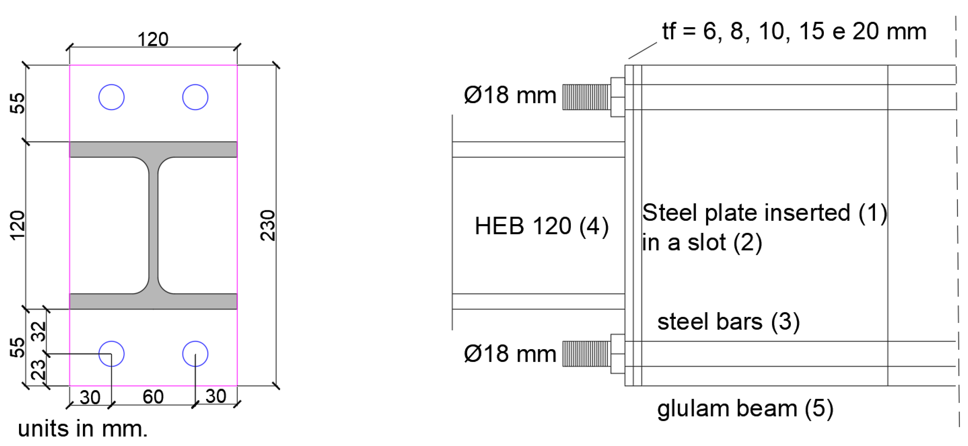
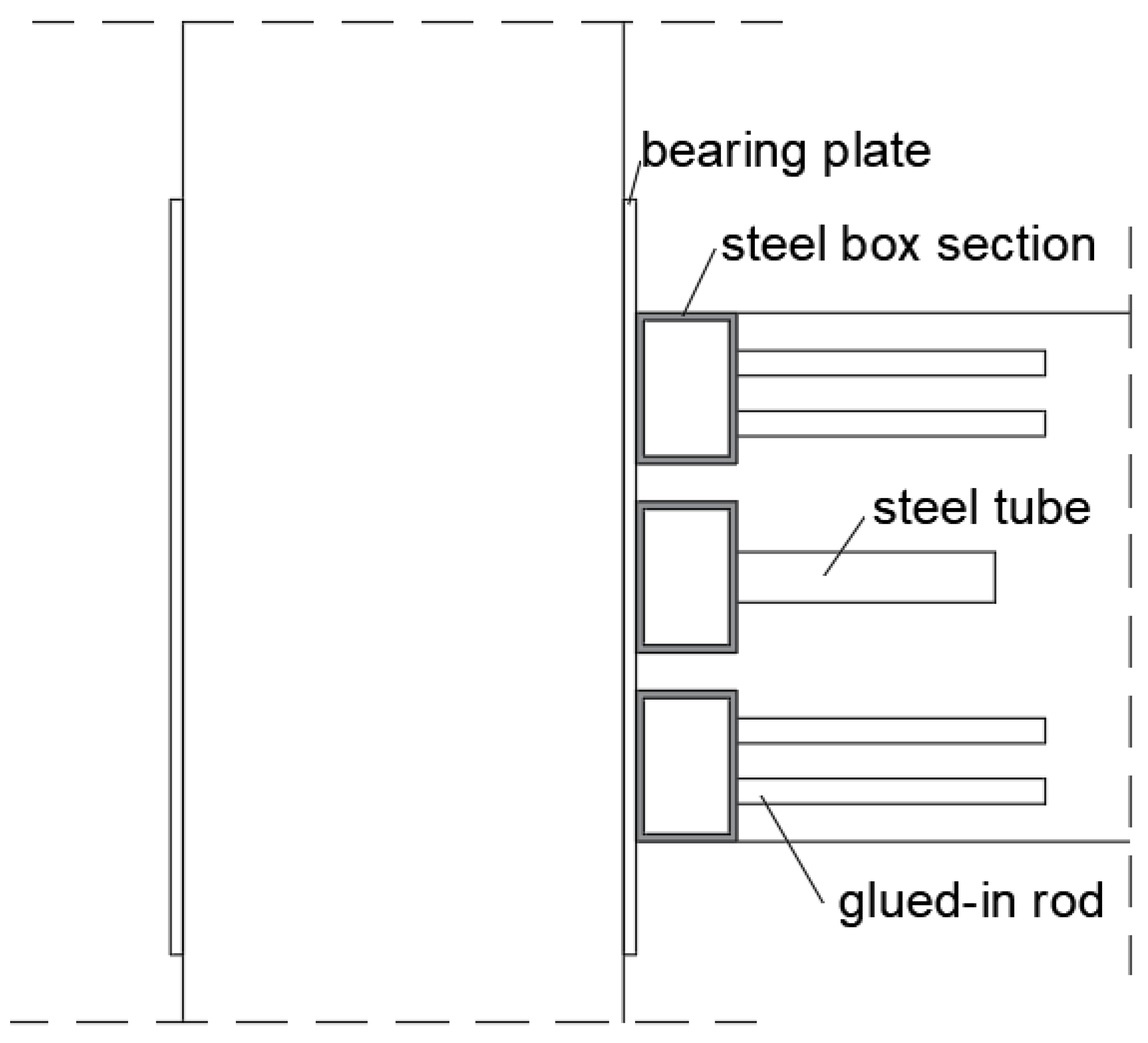
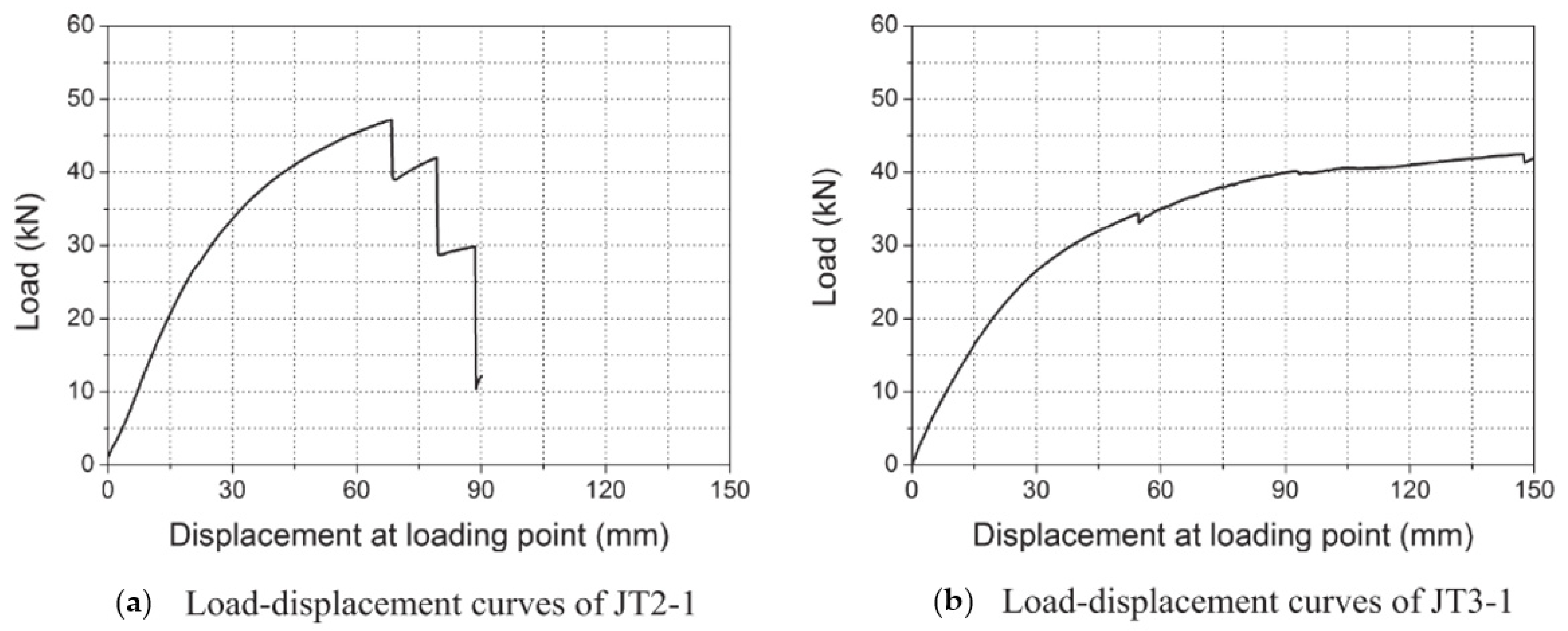
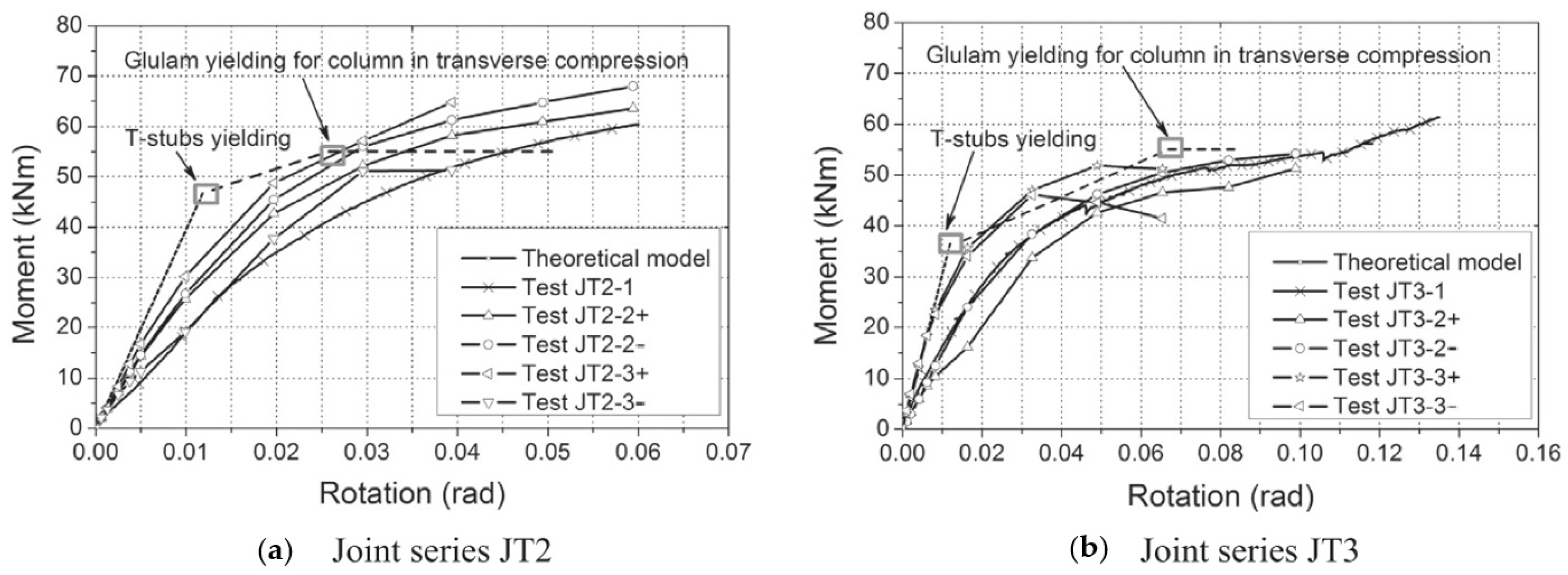
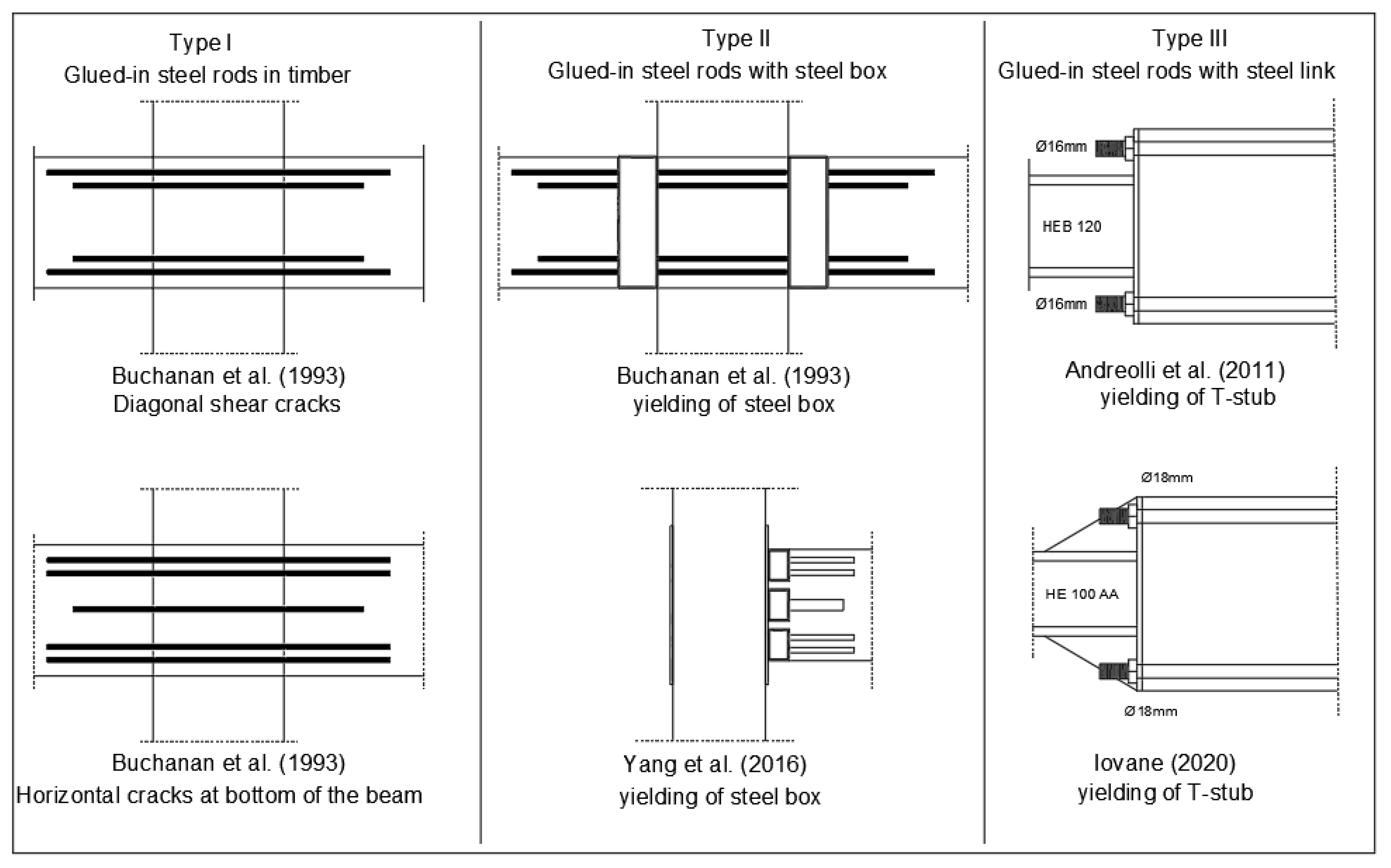
4.2. Glued-in Rods Connections
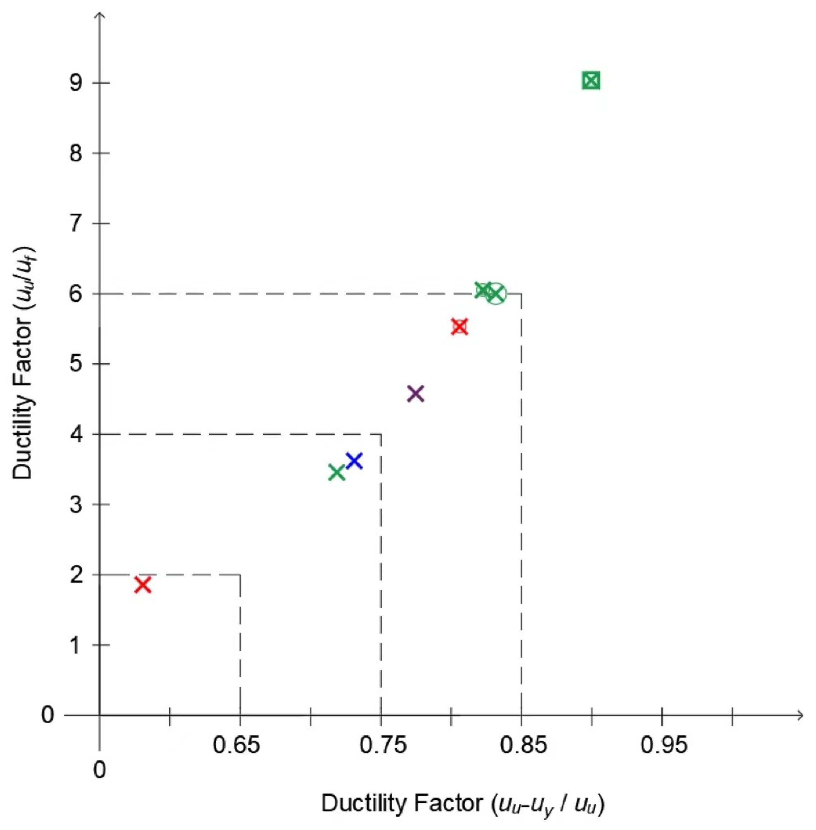
Refs. [37,38] studied the pull-out capacity of glued-in steel rod connections, while [39,40] investigated the use of circular dowel-type fasteners glued into glulam timber to achieve stronger moment-resisting joints. By increasing the friction between the surface of the fastener and the timber that bears it, considerable increases in joint strength and ductility can be achieved [41]. In glued-in rod connections, the steel rods are embedded inside the wooden members, which is aesthetically advantageous for cases where the load bearing structure remains visible and provides better protection of the connection from the influence of fire and a possibly corrosive climate [42].
Ref. [43] tested seven types of moment-resisting connections between glulam members using steel bars embedded in the timber parallel to the grain. Three portal frame knee joints and four multi-story beam–column connections were tested. In the Figure 15a a knee joint with epoxied bars passing through the rafter, in Figure 15b a mitred connection with steel bars welded to a steel plate in the mitre and in Figure 15c a joint with a steel bracket connected to reinforcing bars The multi-story connections tested are shown in Figure 16, where Figure 16a presented a threaded rods connection without steel brackets, Figure 16b a connection with box steel brackets, Figure 16c a connection with central steel joint and Figure 16d a connection with lateral steel brackets and nailon plates.
A capacity design was adopted to ensure ductile yielding in all beam-to-column connections, and the ductility response of each connection was analyzed under cyclic loading. Most of the connection did not exhibit significant ductility because of premature wood failures associated with drilled holes through the rafter or to the split that occurred near the inner bars at low load levels. Based on the experimental hysteresis loops obtained, it is possible to conclude that only the steel bracket portal frame knee joint (Figure 15c) is suitable for a ductile seismic design. As a consequence, a maximum ductility factor of 2.0 was recommended for establishing the design forces. Larger values for ductility were achieved in the tests, but they could not always be sustained for a large number of cycles.
Related to the multi-story beam–column connections (Figure 16), better performance was achieved by the steel bracket joint (b). In this case, good behavior with a ductility factor of ±6.0 was achieved. Local splitting of the steel flange near the weld to the web reduced the load slightly in the last cycle.
The good performance of this connection geometry stimulated several research groups to investigate the mechanical response of a single glued-in bar inserted both parallel and perpendicular to the grain, theoretically and experimentally [44,45,46], while [47] testing multiple rods. In fact, there was an international effort to increase the knowledge about this kind of timber joint through research and others, such as the European research project GIROD-Glued in rods for timber structures [48].
Ref. [49] investigated ductility through the yielding of steel rods within glulam. Three different arrangements of bars were considered: center bar, angle bar, and tie bar (TB) specimens.
Under monotonic tests, the center bar specimens (Figure 17a) failed in shear and in tension, the two angle bar specimens (Figure 17b) failed in shear with a longitudinal crack down the center of the beam., while the tie bar arrangement (Figure 17c) had the best performance because it reached a moment of 155 kNm and to the maximum timber stress of all of the arrangements studied. Specimen TB-2a failed due to yielding in the support frame, while TB-2b failed in tension.
Only the tie bars (TB) arrangement was submitted to cyclic loading. The specimens TB-4, TB-5, TB-6, and TB-7 failed after several cycles, before reaching a ductility of 4. During monotonic and cyclic tests, shear cracks were observed to propagate from the end of the beam. This suggests that the yielding of the steel rods inside the timber was creating internal damage leading to shear failures. Therefore, for a ductile seismic design, yielding of steel connecting brackets is preferred to yielding of the rods [49].
Refs. [50,51,52] studied the steel box sections in glued-in rod connections by a series of experiments. The test results showed a ductile mode, with the steel box section yielding prior to the failure of the glued-in rods.
Refs. [53,54] proposed a joint in which a timber element is connected to a steel stub by means of an end-plate and glued-in steel rods (Figure 18). The transmission of the bending moments occurs through the end-plate and steel bars, while the shear occurs through the glued-in steel plate between the timber element and the steel section. Monotonic and cyclic tests were executed over this joint in order to observe the failure modes while measuring the moment resistance and rotation capacity. In this research, a steel profile (4) was connected to a reinforced timber element (5) via end-plate elements. The transfer of the bending moment was assured by the presence of steel bars glued in the timber elements (3), while the shear forces were transmitted by means of a glued steel plate (1) inserted in a central slot grooved at the end of the timber element (2) (Figure 18).
First, six specimens, varying the thickness of end-plate, were tested under monotonic load to obtain the failure mode of T-stub, tension resistance, and load–displacement curves. The capacity design was applied to ensure the failure of the T-stub. All specimens presented a ductile failure mode, except P10w and P20w specimens, where the shear load is directly supported by the steel bars. However, the adhesive was not able to follow such large strains; a progressive reduction in the glued length took place, and therefore the joint exhibited brittle failure. The joint P20w (reduced section of the bar) also presented brittle failure, through the mode 3. The load–displacement curves of each specimen at monotonic loads are presented in Figure 19.
It is important to notice that if an appropriate steel end-plate thickness is adopted, an overstrength factor can be ensured. In fact, in all the tests performed, the failure modes involved the joint and not the timber elements. In the cases considered, the overstrength of the timber element was guaranteed by the use of steel-reinforced glulam beams.
After, the moment–rotation relationship of the joint was evaluated, and its ductility under cyclic tests was assessed. All specimens collapsed for failure in bending of the end-plate near the weld due to low cyclic fatigue, except for P20-sp, in which a local bar failure mechanism was observed. Figure 20 shows a comparison of the hysteretic moment–rotation relationships with the monotonic experimental curves for two specimens (P6 and P10). Fracture of the end-plate occurred after a number of cycles at large plastic displacement, with a limited reduction in resistance in subsequent cycles.
In a similar study, ref. [55] proposed a connection with three separate steel box sections connected with glued-in rods or glued-in steel tubes to a glulam beam end and with connecting bolts to glulam column (Figure 21).
The steel box section presented in the middle of the connection was combined with a glued-in steel tube in order to mainly transfer the shear force and to prevent shear failure of the connection, while the other two steel box sections combined with glued-in rods were used to transmit the bending moment. The thickness of the tube wall and stiffener was 6 mm, while the cross-sectional size was 120 mm × 80 mm with a length of 135 mm. The size of the rectangular washers (backing plates) under the nuts was 67.5 mm × 40 mm × 6 mm. Steel plates were characterized as grade S235, with a modulus of elasticity Es = 200 GPa, nominal yield stress fy = 310 MPa, and an ultimate strength fu = 420 MPa.
The glulam had average moisture content of 15.0%, with a standard deviation of 0.70, while the average density was 530 kg/m3 with a standard deviation of 20.0. The bolt and glued-in rods were grade 8.8, with a yielding strength of 640 MPa and an ultimate strength of 800 MPa, while the grade of the glued-in steel tube for resisting shear was S235. Moreover, the grade of the backing plates and bearing plates was S235. A two-component epoxy resin with a density of about 1500 kg/m3 and glue-line thickness of 2.0 mm was used to bond the rods to glulam beams.
Three series of specimens were tested: one under monotonic load and the other two under cyclic loading. All of the specimens exhibited reasonable ductility. The load–displacement curve and moment–rotation curves are shown in Figure 22 and Figure 23.

5. Discussion

5.1. Ductility Comparison between Main Connection Types

The bolted with slotted-in steel plates moment-resistant connections are widely used around the world. However, when unreinforced, this kind of connection presents low moment capacity and a brittle failure when subjected to cyclic tests [56,57]. Nevertheless, the introduction of reinforcements can improve its structural performance. As presented in Table 5, the application of self-tapping screws (STSs) perpendicular to grain increases the initial stiffness and the moment capacity of the connection and expands the rotation capacity. Nevertheless, even when STSs are applied, in most cases the failure mode is still brittle, but there is a high deformation level.
On the other hand, the glued-in rods’ moment-resistant connections are built with rods parallel to the grain connected to a steel T-stub or boxes that can change its failure mode to a ductile one. Although there is little research that applied this connection to a moment–rotation heavy timber structure, as presented in Table 6, this connection has demonstrated a good level of rotation capacity. However, the moment resistance is low when compared with the bolted connections reinforced with STS, perhaps, due to the small height of the beams used in the tests performed. Furthermore, to better identify the behavior of the connection related to ductility and its ability to maintain the moment capacity along cycles, it is necessary to carry out more cyclic tests.
Studies on glued-in rods applied in beam-to-column connections with multiple horizontal bars parallel to the beam grain have reported brittle failures, with diagonal shear cracks in the middle of the joint. A better ductile performance of this type of connection was achieved by the geometric configuration I (b), where one rod was inserted at middle of the joint (Figure 24). It reached multiple loading cycles and a ductility factor of 6. The geometric configuration of 20° slanted bars or four bars at the end with near-support tie bars did not perform well with respect to ductility (see Figure 17b). When a confining system for the bars (transversal screws) is applied to beam-to-beam moment connections under cyclic loads (Type I (c)), the connections present an initial high dissipative capacity, but after a few cycles, the energy dissipation is considerably reduced by the occurrence of longitudinal splitting in the timber edge of the joining bars, leading to lateral instability of the rods. Even when the configuration and number of the bars was changed, the failure mode remained the same.
Based on the studies related to glued-in rods associated with steel boxes and tubes (type II on Figure 24), a ductile behavior was observed in the monotonic and cyclic tests, the failure being in the steel side and not on the timber member. The application of three boxes and STSs for reinforcement is beneficial, as it improved the moment resistance of the connection and reduced the probability of cracks and splitting near the supports. On the other hand, when the web thickness of the steel box is very thin, the connection buckles diagonally between the stiffeners and cannot reach high ductility.
Type III (Figure 24) presented the highest degree of ductility due to its high rotational capacity. The preponderant failure mode in this steel link connection geometry was the ductile T-stub yielding, which is always designed to govern the structural behavior of the connection. It was possible to find out that, when the end-plate thickness increases, greater is the joint moment resistance and lower is the rotation capacity. In most research, the specimen with the thicker end-plate exhibited a fragile bar failure. Therefore, by increasing the end-plate thickness, the connection becomes less ductile, changing from a connection classified as one with high ductility to one with low ductility, according to classification proposed by [12]. In general, the works that had inserted steel plates showed a reduction in maximum rotation at the ultimate moment, which also shows a reduction in ductility. [59]
Based on past research, the graph in Figure 25 compares the performances of the most representative moment–rotation timber connections in terms of ductility, using the ductility factors suggested by EN 12512 [7] (graph ordinate) and [10] (graph abscissa).
The connections that present highest levels of ductility are the glued-in rods, classified as high ductility according to [12]. Bolted slotted-in plate connections reinforced with STSs and self-drilled dowels (SDDs) also present a good level of ductility, but are, in general, classified as moderate ductility. However, it is important to note that the glued-in rod connections normally have a smaller moment capacity than the reinforced bolted slotted-in plates ones.

5.2. Recommendations to Achieve Ductility

From the experimental data collected and analyzed within this work, it is possible to trace a practical path to analyze the ductility of a timber connection. First, it is necessary to know the moment–rotation curve of the joint. From it, the initial stiffness and the yield point must be defined. Moment–rotation curves need to reach a clear plateau for yield point definition and should reach maximum rotation values close to 0.15 rad (monotonic) and 0.10 rad (cyclic), without significant loss of moment resistance at this ultimate point. Moreover, when tested, ductile connections should preferably have a ductile failure mode. Even if different definitions of ductility exist, in the light of the above parameters and considering the two different expressions for the ductility (Equations (2) and (13)), it was possible to obtain coherent values for the ductility ratio (see Figure 25).
Although several semi-rigid connections were studied and tested in order to evaluate their ductility, few comparisons between the different types of ductile timber connections have been made. From the state-of-the-art review performed, the following suggestions to obtain ductile timber connections are proposed.
For slotted-in steel plate connections:
i.
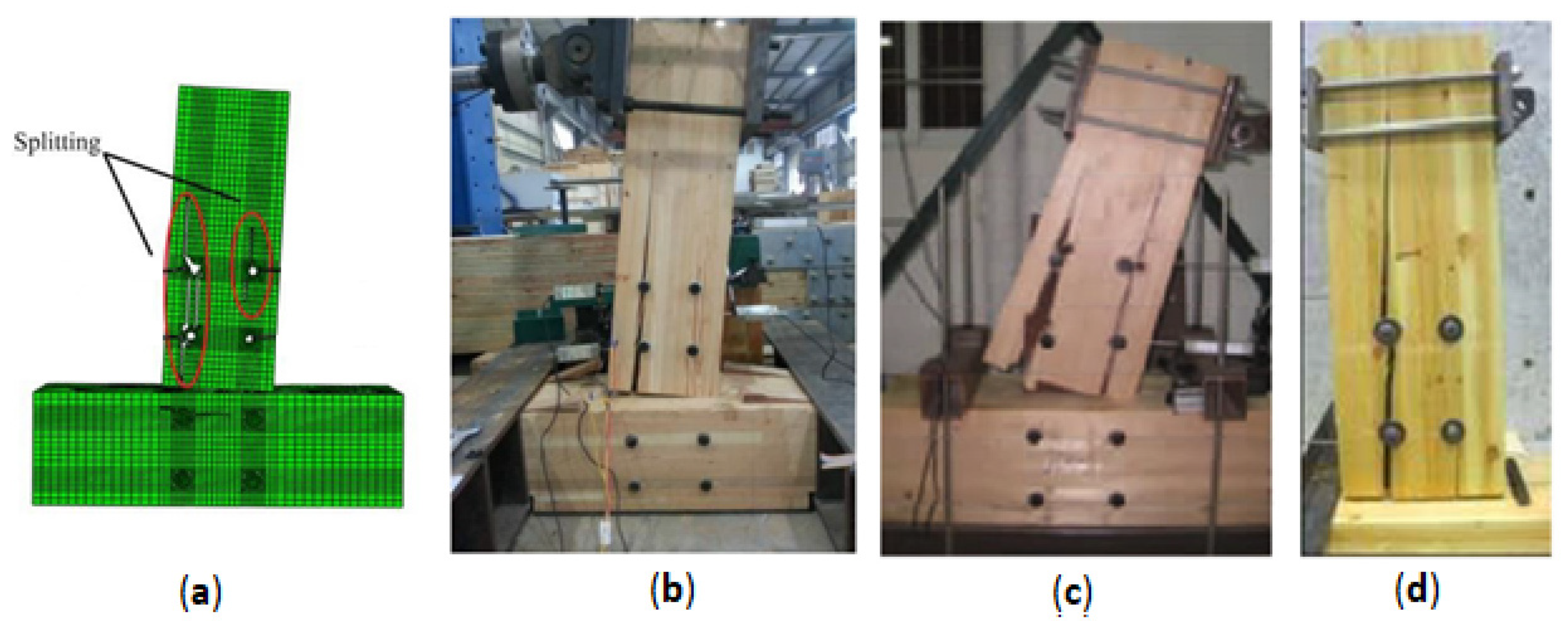
Eurocode 5 [7] recommends minimum spacing requirements to avoid brittle failures in dowel-type connections. Nevertheless, in connections that transmit bending moments, even meeting Eurocode 5 criteria, brittle failures were observed (such as timber splitting), causing low connection ductility. Thus, for semi-rigid dowel-type connections that need to reach ductile behavior, a specific design procedure must be followed [19,36].
ii.
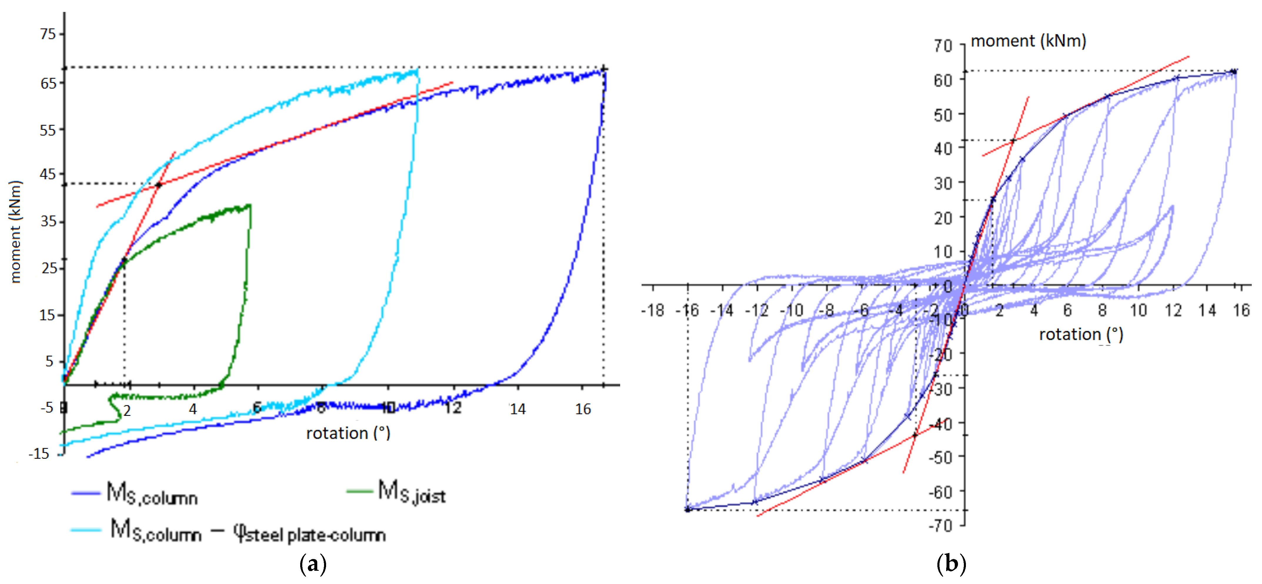
When the slotted-in steel plate connection is designed without reinforcement, the bending moment is not considered in the design process, and the connection can fail prematurely. In this case, its structural behavior is governed by tension perpendicular to grain and longitudinal shear, which are the properties of timber that have the weakest strength [25,30]. In these cases, to achieve a safe design, slotted-in steel plates should be considered for reinforcement with self-tapping screws (STSs) perpendicular to the grain. Thus, perpendicular-to-grain stresses are transmitted by tensile stresses along the STSs, and the connection capacity is governed by strong tensile strength of the screw’s steel [33].
iii.
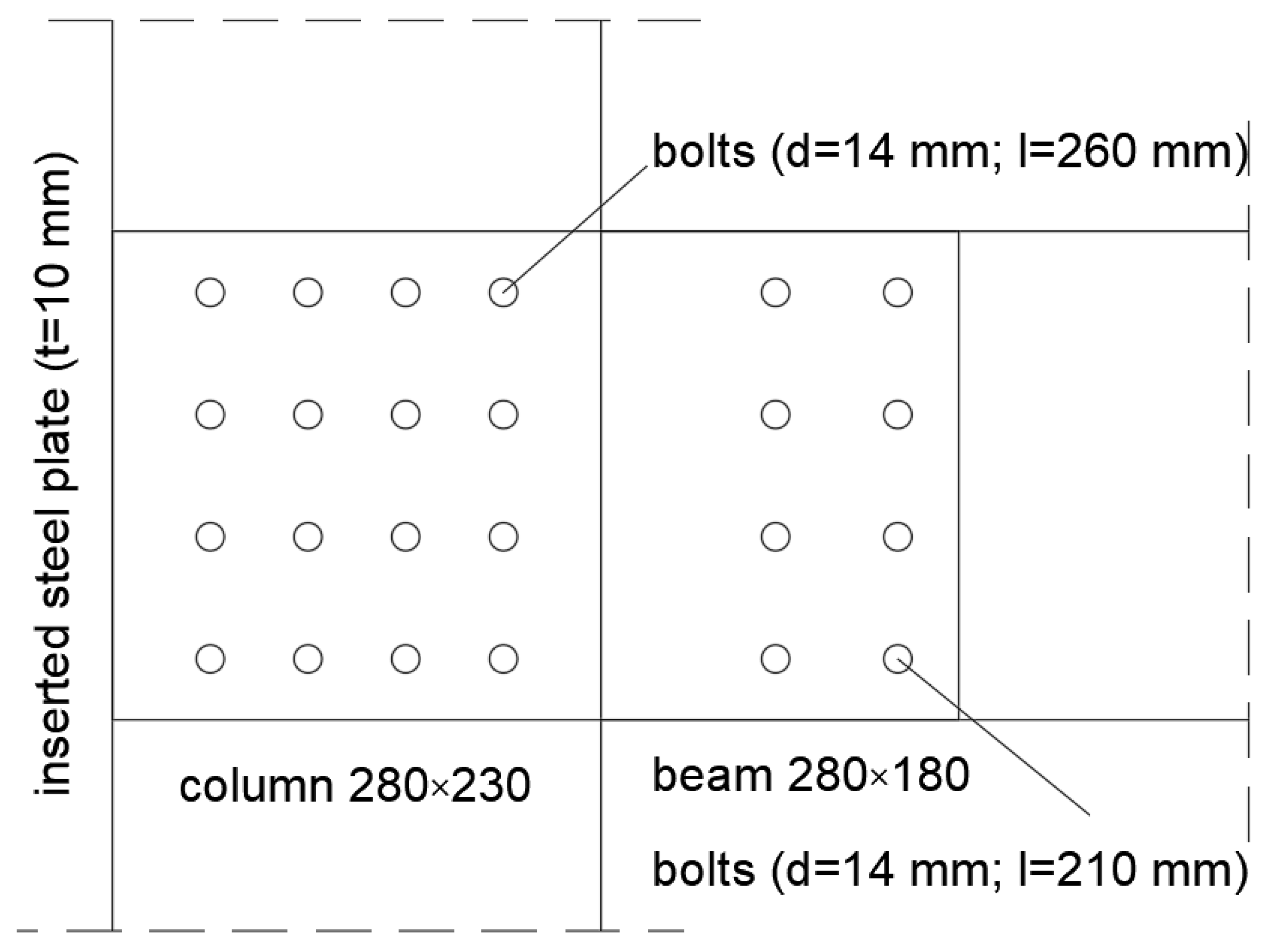
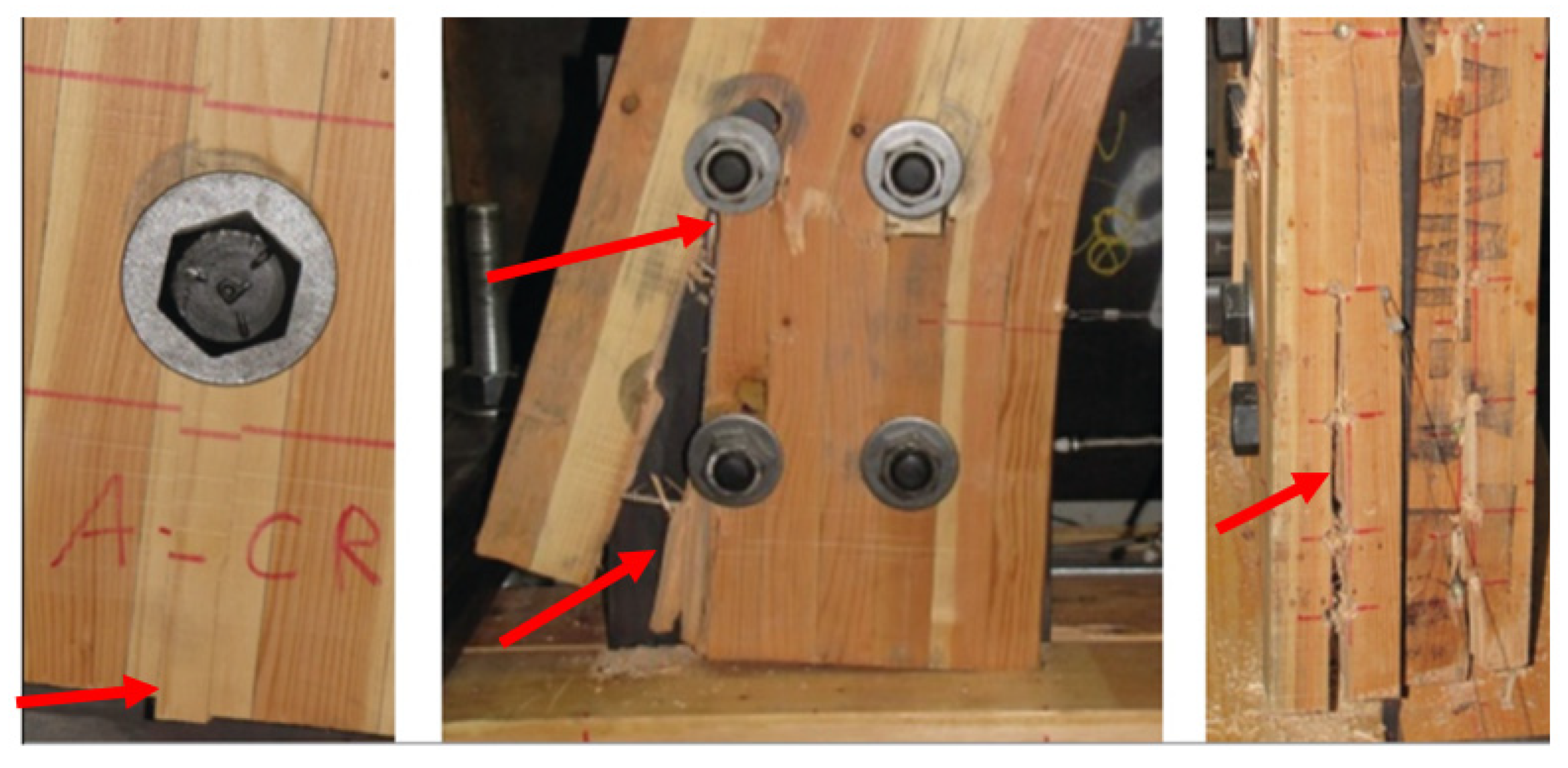
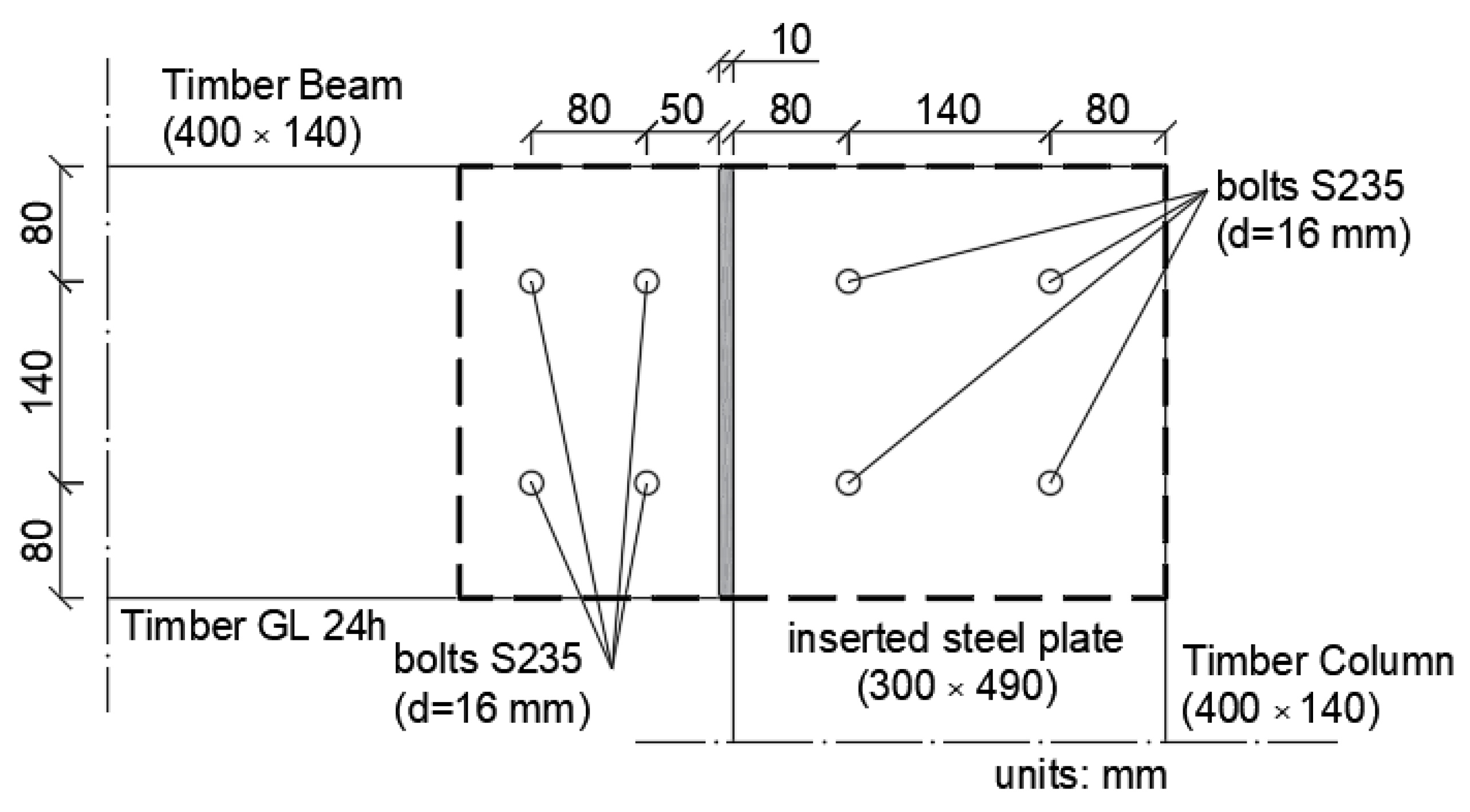
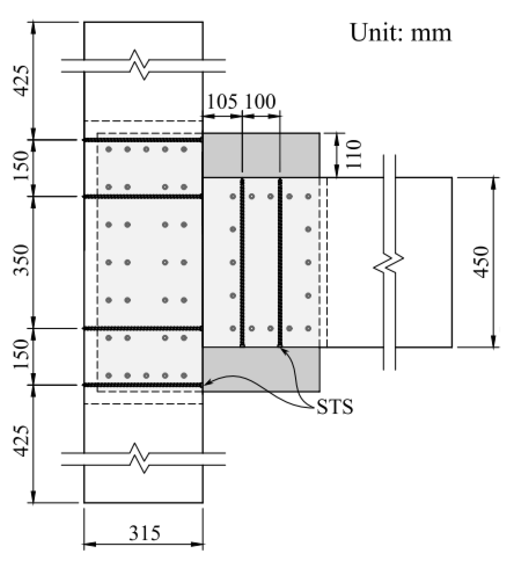
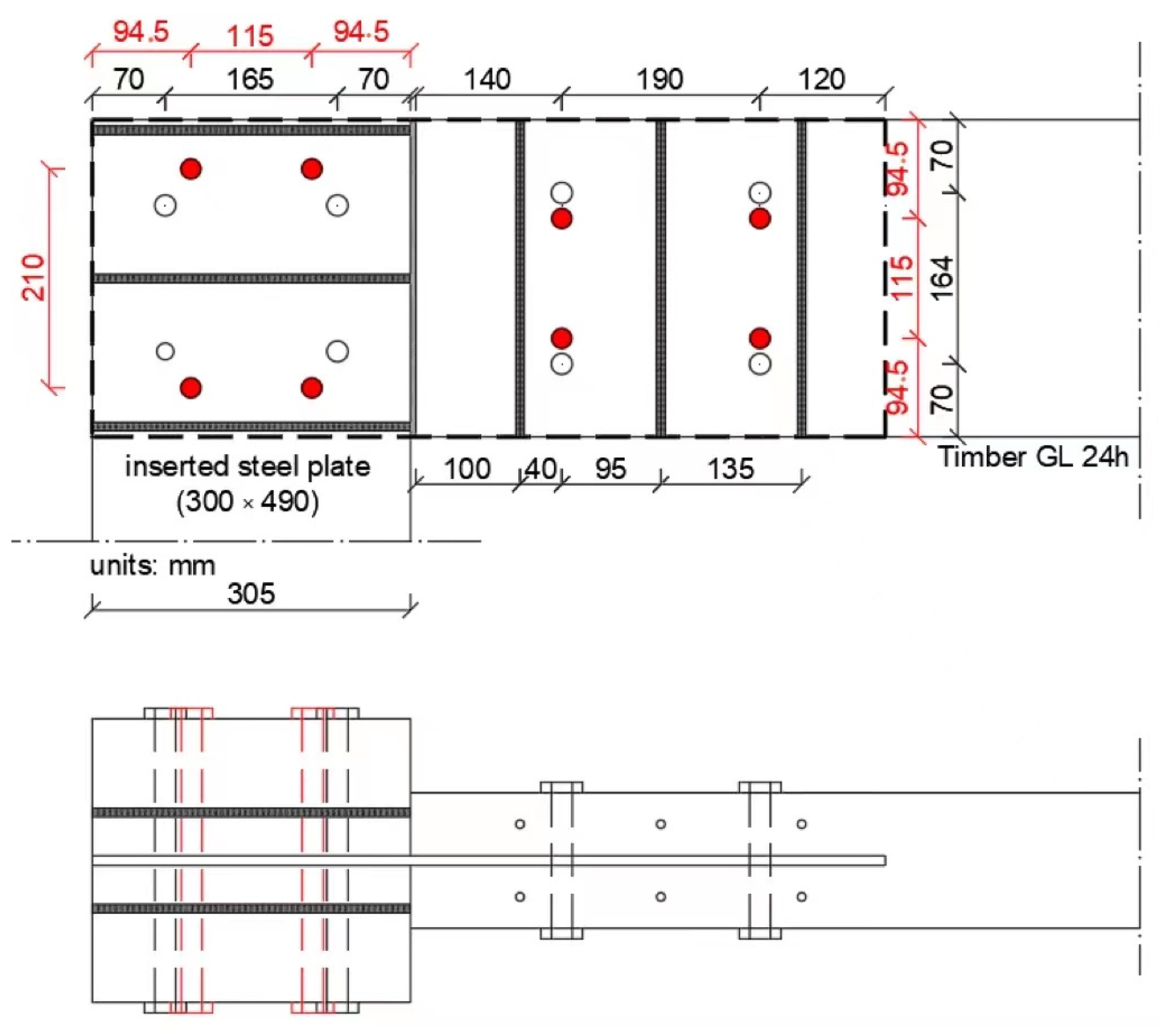
In slotted-in steel plate connections reinforced with STSs perpendicular to grain, most available studies used a common geometry of approximately 300 mm for columns and beams height and 8 bolts per connection and STSs close to the bolts to prevent splitting and increase the rotational capacity of the connection (see Figure 14). When the distance between the center of the external bolt and timber edge is small (49.5 cm in [30]) and the bolt diameter is higher than 19 mm, the connections exhibited higher moment resistance but presented brittle failure and lower energy dissipation capacity. In the absence of more data, and although there is still no analytical method that allows a reliable prediction of that connection behavior, to achieve a good degree of ductility, it is recommended that bolts with a diameter of 19 mm and a distance of up to 70 cm between the center of the bolts and the timber edge are used.
For glued-in rod connections:
i.
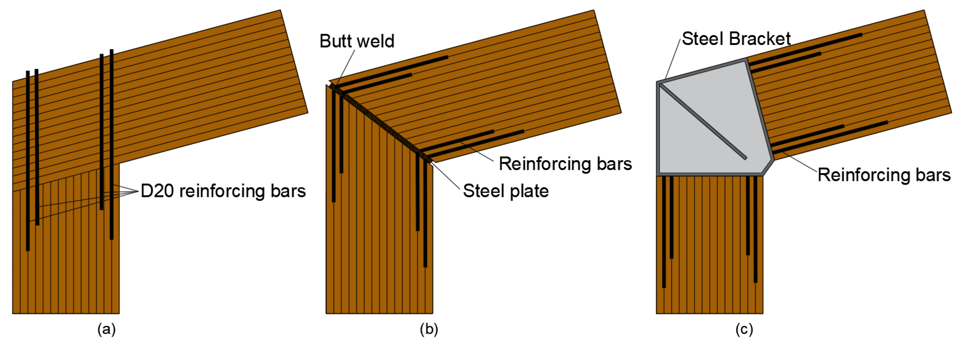
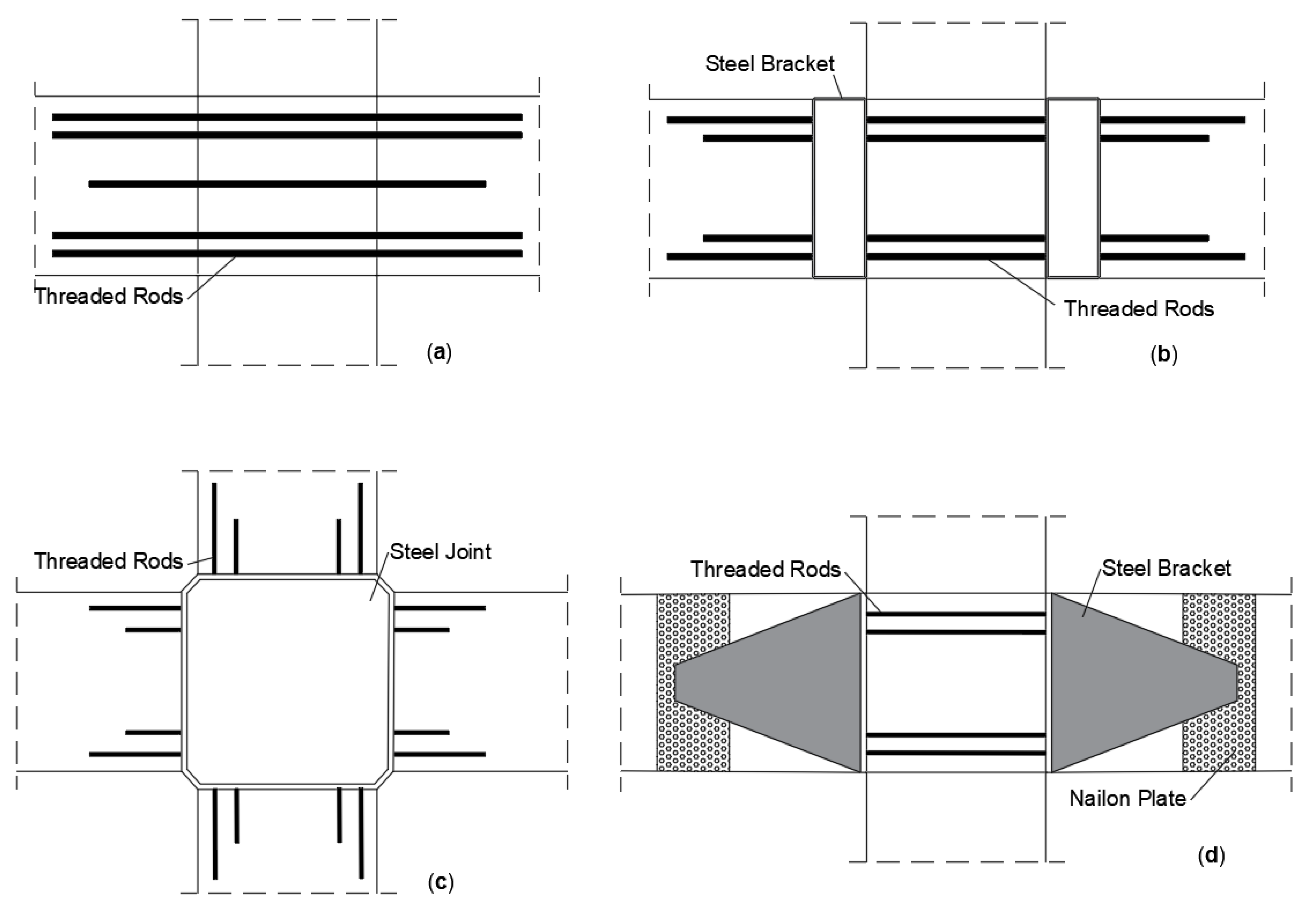
It is recommended that ductility is achieved by connecting a steel profile or bracket together with the rods attached to the timber. In studies where only threaded rods were inserted directly on timber, a brittle failure was observed, probably due an internal damage caused by rods, leading to shear failures [49].
ii.
In connections that have a steel profile and an end plate connected to rods, the capacity design is applied to ensure that the steel link yields before the timber. However, this procedure may not ensure a ductile failure of the connection. Therefore, to avoid a brittle failure, it is recommended that the connection have not only the rods as elements resistant to shear but also a steel plate that shall be inserted parallel to the grain to contribute to the shear resistance of the joint [53,54].
iii.
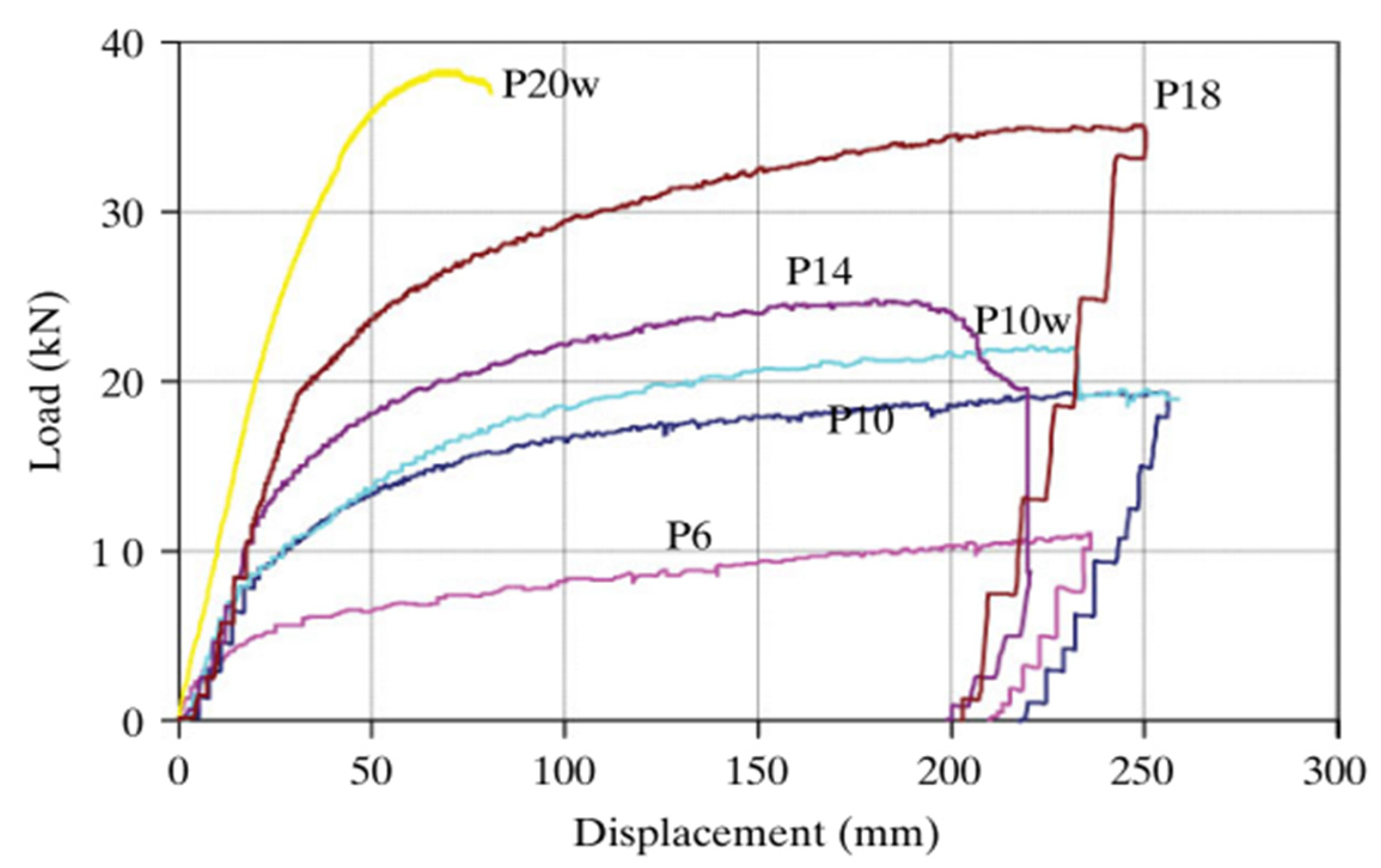
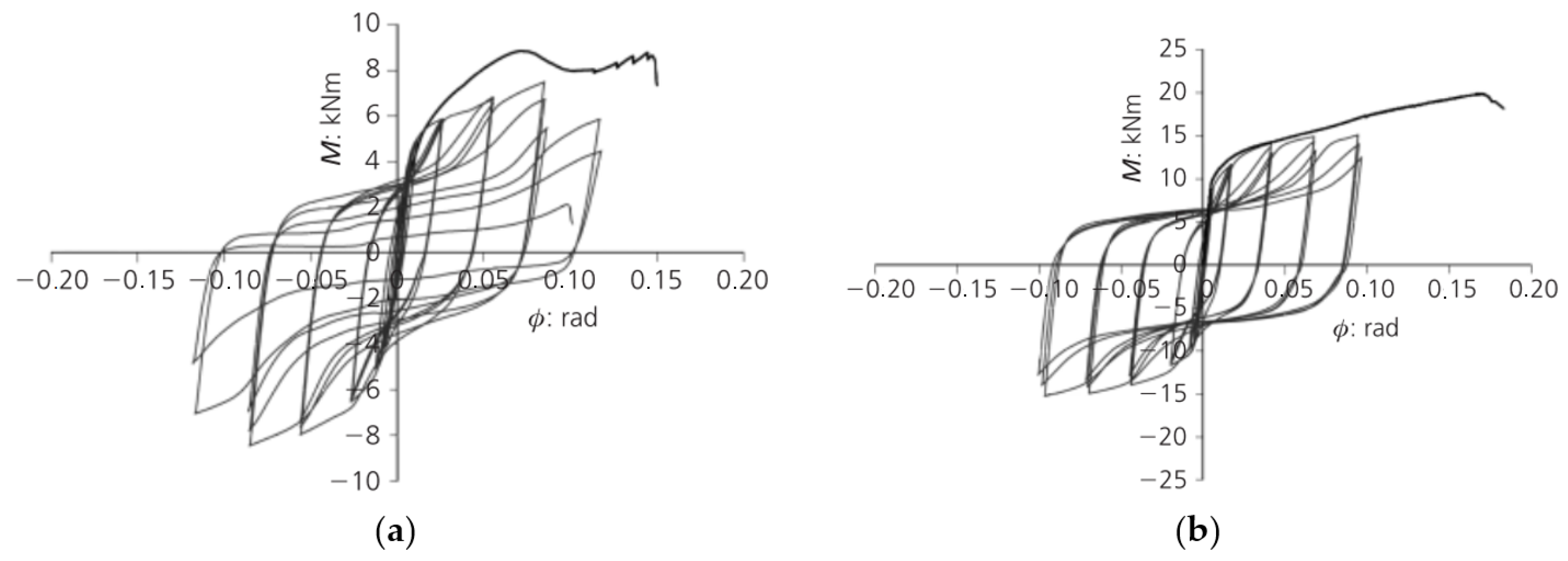
The application of thicker end-plates or steel boxes is associated with a greater stiffness of the connection and may lead to higher moment capacity, but it also may lead to a brittle failure and low rotation capacity. Thus, to obtain a ductile connection, a thickness of 6 to 10 mm was enough in most of studies [54,55].
iv.
A proposition of stiffeners attached to end-plates or inserted into steel boxes is also interesting, in order to obtain a larger joint initial stiffness.

5.3. Challenges

The analysis of the current state-of-the-art indicates the need to study timber frames and/or buildings under lateral loading with the aim of assessing the displacement and stiffness responses of the connections.
Within the moment-resisting timber frames system, without bracing or shear walls, the rotational stiffness of the joints is crucial, as we are dealing with statically indeterminate structures, and the internal forces redistribution is controlled by the ductility ensured by connections. For example, in the case of a multi-story moment-resisting timber frame structure, to fulfil the stated service limit requirements due to lateral deflections and accelerations induced by wind loads, the connections must have a minimum rotational stiffness [21].
First attempts to adopt semi-rigid slotted-in steel plate connections on portal timber frames under monotonic load obtained a linear behavior with high moment capacity, but a brittle failure occurred at low rotation level. Its application on portal frames submitted to cyclic loading test, without lateral reinforcements, presented inadequate rotation stiffness to resist lateral displacements [19,20].
On the other hand, although the glued-in rod connections were studied in several research studies [43,49,50,51,53,54,55], there are still no consistent results or publications that allow evaluating their application in a portal frame. However, based on the joint behavior assessed within this work, in particular, taking into account the rotational stiffness obtained in the available test results, one can conclude that connections that contain laterally loaded fasteners (slotted-in steel plate) have lower stiffness than those with axially loaded fasteners (glued-in rods). This, combined with its greater ductility, shows that this type of connection has great potential for application in moment-resisting timber-frame buildings.
To promote the use of the moment-resistant timber frame system in medium- and high-rise buildings, it is essential to find an accurate analytical methodology for predicting the connection semi-rigid response—namely, moment-rotation law and ductility. In the literature, it is possible to find analytical models for some types of semi-rigid joints. Even though a greater number of developments are still necessary, it is clear that it is possible to develop design guidelines and recommendations to analyze the response of the semi-rigid joints and with that to be able to predict the behavior of the corresponding moment-resistant timber frame structures.

6. Conclusions

This paper presents a review of the most important research studies that have focused on ductile beam-to-column connections in the moment-resisting timber frame system. The measurement of ductility in connections is still a complex task because there are several proposals in the literature that provide different results. Therefore, initially a discussion was carried out on the most relevant definitions of ductility.
The first applications of moment-resisting connections on timber portal frames showed premature splitting and high lateral displacement of the frame, but the application of ductile connections has improved the mechanical parameters of the frame, with increased ultimate load and reduced horizontal displacement. Timber frames experienced large deformation, in some cases, without significant load drop or collapse. In all past studies, joints had a significant influence on the global performance of the timber frame. Most research was carried out using reinforced bolted slotted-in plate connections, while few works presented an experimental evaluation of moment-resisting timber frame with glued-in rods connections.
Regarding mechanical performance, the bolted slotted-in plate connections, widely used, have shown good rotation capacity and ultimate moment results when reinforced with STSs. In several studies, these connections were able to maintain high load levels for more than four load cycles. However, the connections showed brittle failure modes at high levels of deformation after several loading cycles.
The studies on connections with a locally cross-laminated technique showed lower results than those reinforced with STSs. On the other hand, although there are few studies that evaluated the behavior of glued-in rods connections under cyclic loads, it was possible to observe that connections built without metallic profile presented premature wood failures at low loads. The application of inclined bars showed that steel rods inside the timber created internal damage, leading to shear failures. However, when associating steel profiles or steel boxes with the bars, the mechanical performance improves, reaching high values of rotation capacity and moment resistance. In general, in these types of connections, the steel profile or box section yielded prior to the failure of the glued-in rods, leading to ductile failure modes.
Based on the two most representative formulations for ductility factors, an evaluation of connection ductility was carried out. In general, the glued-in steel rods presented better results, probably because of the high influence of steel profiles in the yielding connection. Despite the excellent mechanical behavior, the reinforced bolted slotted-in steel plate connections had medium ductility values because they have higher rotation at yield values, which generates small plastic regions where energy dissipation is more important. Although significant work has been performed on the ductility assessment of timber joints, there are still open questions. Moment-resistant timber connections are governed by very complex mechanisms and are dependent on a large number of geometrical, material, and configuration parameters and their combinations. The implications of their performance on moment-resistant timber frames are even broader and need to be evaluated from the point of view of the global behavior of the structure.

Author Contributions

A.S.R. and Z.M., methodology, formal analysis, investigation, writing—original draft preparation; J.M.B. and P.B.L., conceptualization, methodology, formal analysis, writing—review and editing, supervision. All authors have read and agreed to the published version of the manuscript.

Funding

This research was funded by Fundação para a Ciência e a Tecnologia (FCT) grant number BD/06301/2022.

Institutional Review Board Statement

Not applicable.

Informed Consent Statement

Not applicable.

Data Availability Statement

The data presented in this study are available on request from the corresponding author.

Conflicts of Interest

The authors declare no conflict of interest.

References

  1. Abrahamsen, R. Mjøstårnet-Construction of an 81 m Tall Timber Building. Int. Hoizbau-Fourm IHF 2017, 2017, 1–12. [Google Scholar]
  2. Vilguts, A.; Malo, K.A.; Stamatopoulos, H. Moment Resisting Frames and Connections Using Threaded Rods in Beam-to-Column Timber Joints Moment Resisting Frames and Connections Using Threaded Rods in Beam—To-Column Timber Joints. In Proceedings of the World Conference on Timber Engineering, Seoul, Korea, 20 August 2018. [Google Scholar]
  3. CEN Eurocode 8: Design of Structures for Earthquake Resistance—Part 1: General Rules, Seismic Actions and Rules for Buildings; European Committee for Standardization: Brussels, Belgium, 2004; Volume 1.
  4. Ding, Y.; Zhou, Z.; Huang, L.; Si, Y. Seismic Performance of Self-Centering Glulam Frame with Friction Damper. Eng. Struct. 2021, 245, 112857. [Google Scholar] [CrossRef]
  5. Park, R. Ductility Evaluation from Laboratory and Analytical Testing. In Proceedings of the 9th World Conference on Earthquake Engineering, Tokyo–Kyoto, Japan, 2 August 1988; Volume 8, pp. 605–616. [Google Scholar]
  6. Swiss Society of Engineers and Architects SIA. Design Code SIA 265 Timber Structures. Swiss Stand. Assoc. 2003. Available online: http://shop.sia.ch/ (accessed on 12 April 2021).
  7. CEN. EN 12512—Timber Structures—Test Methods—Cyclic Testing of Joints Made with Mechanical Fasteners; CEN: Brussels, Belgium, 2001. [Google Scholar]
  8. Blaß, H.J.; Schädle, P. Ductility Aspects of Reinforced and Non-Reinforced Timber Joints. Eng. Struct. 2011, 33, 3018–3026. [Google Scholar] [CrossRef]
  9. Stehn, L.; Björnfot, A. Comparison of Different Ductility Measurements for a Nailed Steel-to-Timber Connection. In Proceedings of the 7th World Conference on Timber Engineering WCTE, Shah Alam, Malaysia, 12–15 August 2002. [Google Scholar]
  10. Ottenhaus, L.-M.; Jockwer, R.; van Drimmelen, D.; Crews, K. Designing Timber Connections for Ductility—A Review and Discussion. Constr. Build. Mater. 2021, 304, 124621. [Google Scholar] [CrossRef]
  11. Muñoz, W.; Mohammad, M.; Salenikovich, A.; Queeneville, P. Need for a Harmonized Approach for Calculations of Ductility of Timber Assemblies. In Proceedings of the International Councial for Reseach and Innovation in Building and Construction, St. Andrews, Canada, 24–28 August 2008. [Google Scholar]
  12. Smith, I.; Asiz, A.; Snow, M.; Chui, Y.H. Possible Canadian/ISO Approach to Deriving Design Values from Test Data. In Proceedings of the CIB-W18 Meeting in Florence, Florenz, Italy, 28–31 August 2006. [Google Scholar]
  13. Komatsu, K.; Hosokawa, K.; Hattori, S. Development of Ductile and High-Strength Semi-Rigid Portal Frame Composed of Mixed Species Glulams and h-Shaped Steel Gusset Joint. In Proceedings of the 2006 World Conference on Timber Engineering, Oregon State University Conference Services, Portland, OR, USA, 6–10 August 2006. [Google Scholar]
  14. Noguchi, M.; Takino, S.; Komatsu, K. Development of Wooden Portal Frame Structures with Improved Columns. J. Wood Sci. 2006, 52, 51–57. [Google Scholar] [CrossRef]
  15. Ishigaki, H.; Sakamaki, Y.; Ishikawa, Y.; Hara, T.; Ohashi, Y. A Study on Seismic Performance of Timber Structures with Moment Resisting Joints. In Proceedings of the 14th World Conference on Earthquake Engineering, Beijing, China, 12–17 October 2008; pp. 1–6. [Google Scholar]
  16. Kasal, B.; Guindos, P.; Polocoser, T.; Heiduschke, A.; Urushadze, S.; Pospisil, S. Heavy Laminated Timber Frames with Rigid Three-Dimensional Beam-to-Column Connections. J. Perform. Constr. Facil. 2014, 28, 1–11. [Google Scholar] [CrossRef]
  17. Xiong, H.; Liu, Y.; Yao, Y.; Li, B. Experimental Study on the Lateral Resistance of Reinforced Glued-Laminated Timber Post and Beam Structures. J. Asian Archit. Build. Eng. 2017, 16, 379–385. [Google Scholar] [CrossRef] [Green Version]
  18. Haibei, X.; Yingyang, L. Experimental Study of the Lateral Resistance of Bolted Glulam Timber Post and Beam Structural Systems. J. Struct. Eng. 2016, 142, E4014002. [Google Scholar] [CrossRef]
  19. Liu, Y.; Xiong, H. Lateral Performance of a Semi-Rigid Timber Frame Structure: Theoretical Analysis and Experimental Study. J. Wood Sci. 2018, 64, 591–600. [Google Scholar] [CrossRef] [Green Version]
  20. Cao, J.; Xiong, H.; Cui, Y. Seismic Performance Analysis of Timber Frames Based on a Calibrated Simplified Model. J. Build. Eng. 2022, 46, 103701. [Google Scholar] [CrossRef]
  21. Vilguts, A.; Stamatopoulos, H.; Malo, K.A. Parametric Analyses and Feasibility Study of Moment-Resisting Timber Frames under Service Load. Eng. Struct. 2021, 228, 111583. [Google Scholar] [CrossRef]
  22. Komatsu, K. Development of Stiffer and Ductile Glulam Portal Frame. AIP Conf. Proc. 2017, 1903, 020026. [Google Scholar] [CrossRef] [Green Version]
  23. Bryant, A.H.; Gibson, J.A.; Mitchell, T.N.; Thurston, S.J. Nailed Moment Joints in Timber Structures. Bull. N. Z. Natl. Soc. Earthq. Eng. 1981, 14, 223–232. [Google Scholar] [CrossRef]
  24. Komatsu, K.; Kawamoto, N. Modified Moment-Resisting Joints. In Proceedings of the 1991 International Timber Engineering Conference London, London, UK, 2–5 September 1991; pp. 3111–3118. [Google Scholar]
  25. Lam, F.; Schulte-Wrede, M.; Yao, C.C.; Gu, J.J. Moment Resistance of Bolted Timber Connections with Perpendicular to Grain Reinforcements. In Proceedings of the 10th World Conference on Timber Engineering, Miyazaki, Japan, 2–5 June 2008; Volume 2, pp. 978–985. [Google Scholar]
  26. ASTM E 2126; Standard Test Methods for Cyclic (Reversed) Load Test for Shear Resistance of Vertical Elements of the Lateral Load Resisting Systems for Buildings. ASTM: West Conshohocken, PA, USA, 2009.
  27. Blaß, H.J.; Bejtka, I. Selbstbohrende Holzschrauben Und Ihre Anwendungsmöglichkeiten; Universität Karlsruhe: Karlsruhe, Germany, 2004. [Google Scholar]
  28. Bejtka, I. Verstärkungen von Bauteilen Aus Holz Mit Vollgewindeschrauben; Universität Karlsruhe: Karlsruhe, Germany, 2005. [Google Scholar]
  29. Blaß, H.J.; Bejtka, I.; Uibel, T. Tragfähigkeit von Verbindungen Mit Selbstbohrenden Holzschrauben Mit Vollgewinde; KIT Scientific Publishing: Karlsruhe, Germany, 2006. [Google Scholar]
  30. Lam, F.; Gehloff, M.; Closen, M. Moment-Resisting Bolted Timber Connections. Proc. Inst. Civ. Eng. Struct. Build. 2010, 163, 267–274. [Google Scholar] [CrossRef]
  31. Wang, M.; Song, X.; Gu, X.; Zhang, Y.; Luo, L. Rotational Behavior of Bolted Beam-to-Column Connections with Locally Cross-Laminated Glulam. J. Struct. Eng. 2014, 141, 04014121. [Google Scholar] [CrossRef]
  32. Solarino, F.; Giresini, L.; Chang, W.S.; Huang, H. Experimental Tests on a Dowel-Type Timber Connection and Validation of Numerical Models. Buildings 2017, 7, 116. [Google Scholar] [CrossRef] [Green Version]
  33. Sun, X.; Qu, Y.; Liu, W.; Lu, W.; Yuan, S. Rotational Behavior and Modeling of Bolted Glulam Beam-to-Column Connections with Slotted-in Steel Plate. Adv. Struct. Eng. 2020, 23, 1989–2000. [Google Scholar] [CrossRef]
  34. Lu, W.D.; Sun, H.F.; Liu, W.Q. Experimental Study on Behavior of Bolted Glulam Beam-to-Column Connections Strengthened by Self-Tapping Screws. Chin. J. Build. Struct. 2016, 37, 80–86. [Google Scholar]
  35. Yasumura, M. Estimating Seismic Performance of Wood-Framed Structures. In Proceedings of the 5th WCTE, Montreux, Switzerland, 17–20 August 1998; Volume 2, pp. 564–571. [Google Scholar]
  36. Dong, W.; Li, M.; He, M.; Li, Z. Experimental Testing and Analytical Modeling of Glulam Moment Connections with Self-Drilling Dowels. J. Struct. Eng. 2021, 147, 4021047. [Google Scholar] [CrossRef]
  37. Riberholt, H. Glued Bolts in Glulam. In Proceedings of the 5th World Conference in Timber Engineering, Montreux, Switzerland, 17–20 August 1998. [Google Scholar]
  38. Townsend, P.K. Steel Dowels Epoxy Bonded in Glulam Timber; Research Report 90-11; Department of Civil Engineering, University of Canterbury: Christchurch, New Zealand, 1990. [Google Scholar]
  39. Rodd, P.D. Timber Joints Made With Improved Circular Dowel Fasteners. In Proceedings of the 1988 International Conference on Timber Engineering, Seattle, WA, USA, 19–22 September 1988; pp. 26–37. [Google Scholar]
  40. Rodd, P.D.; Hilson, B.O.; Spriggs, R.A. Resin Injected Mechanically Fastened Timber Joints. In Proceedings of the Second Pacific Timber Engineering Conference, Auckland, New Zealand, 28–31 August 1989; pp. 131–136. [Google Scholar]
  41. Fairweather, R.H. Beam Column Connections for Multi-Storey Timber Buildings. Master’s Thesis, University of Canterbury, Christchurch, New Zealand, 1992. [Google Scholar]
  42. Tlustochowicz, G.; Serrano, E.; Steiger, R. State-of-the-Art Review on Timber Connections with Glued-in Steel Rods. Mater. Struct./Mater. Et Constr. 2011, 44, 997–1020. [Google Scholar] [CrossRef]
  43. Buchanan, A.H.; Fairweather, R.H. Seismic Design of Glulam Structures. Bull. N. Z. Natl. Soc. Earthq. Eng. 1993, 26, 415–436. [Google Scholar] [CrossRef]
  44. Blass, H.J.; Laskewitz, B. Load-Carrying Capacity of Axially Loaded Rods Glued-in Perpendicular to the Grain. In Proceedings of the International RILEM Symposium on Joints in Timber Structures, Stuttgart, Germany, 2001; pp. 363–371. [Google Scholar]
  45. Buchanan, A.H. Strength of Epoxied Steel Rods in Glulam Timber. In Proceedings of the International Wood Engineering Conference, New Orleans, LA, USA, 28–31 October 1996; Volume 4, pp. 488–495. [Google Scholar]
  46. Del Senno, M.; Piazza, M.; Tomasi, R. Axial Glued-in Steel Timber Joints—Experimental and Numerical Analysis. Holz Als Roh-Und Werkst. 2004, 62, 137–146. [Google Scholar] [CrossRef]
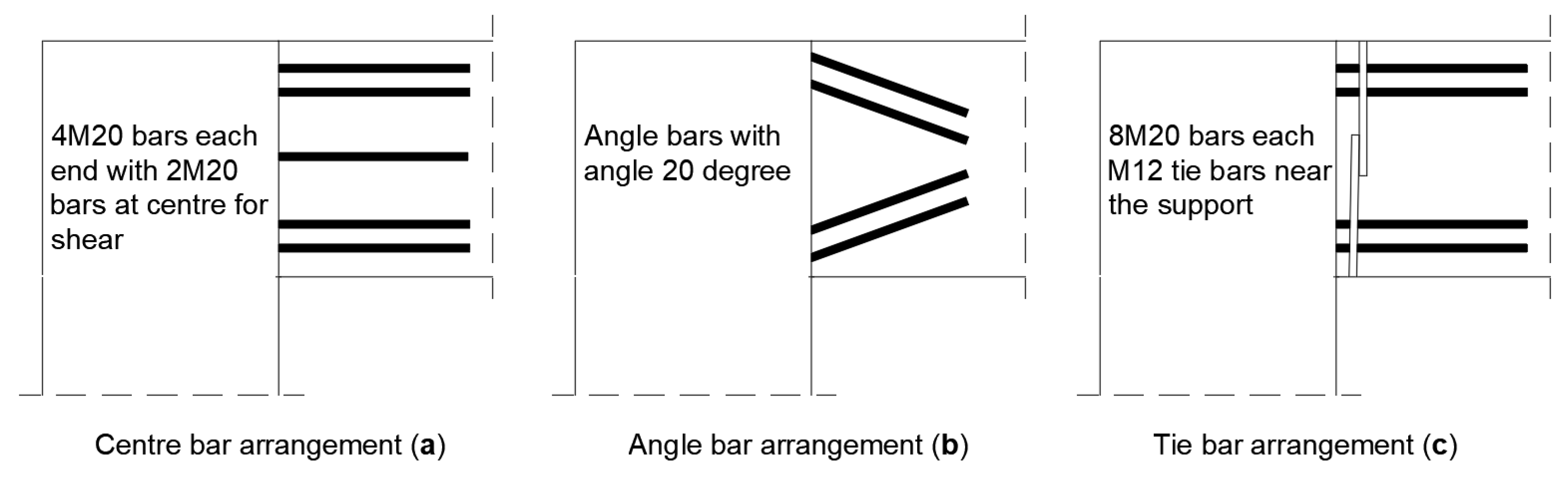
  47. Korin, U.; Buchanan, A.H.; Moss, P.J. Effect of Bar Arrangement on Tensile Strength of Epoxied End Bolts in Glulam. In Proceedings of the Pacific Timber Engineering Conference, Rotorua, New Zealand, 14–18 March 1999; Volume 2, pp. 217–224. [Google Scholar]
  48. Johansson, C.-J.; Bengtsson, C. GIROD-Glued-in Rods for Timber Structures; SP Swedish National Testing and Research Institute: Borås, Sweden, 2002. [Google Scholar]
  49. Buchanan, A.; Moss, P.; Wong, N. Ductile Moment-Resisting Connections in Glulam Beams. In Proceedings of the NZSEE Conference, Wairakei Resort, Taupo, New Zealand, 23 March 2001; pp. 1–9. [Google Scholar]
  50. Vašek, M.; Mikeš, K. The Metal Joints for the Space Timber Structures—The Nonlinear Behaviour. In Proceedings of the World Conference on Timber Engineering, Montreux, Switzerland, 17–20 August 1998. [Google Scholar]
  51. Vašek, M.; Vyhnálek, R. Timber Semi Rigid Frame with Glued-in-Rods Joints. In Proceedings of the 9th World Conference on Timber Engineering, Portland, OR, USA, 6–10 August 2006; Volume 3, pp. 1825–1832. [Google Scholar]
  52. Vašek, M. Semi Rigid Timber Frame and Space Structure Connections by Glued-in Rods. In Proceedings of the World Conference of Timber Engineering, Miyazaki, Japan, 2–5 June 2008. [Google Scholar]
  53. Tomasi, R.; Zandonini, R.; Piazza, M.; Andreolli, M. Ductile End Connections for Glulam Beams. Struct. Eng. Int. J. Int. Assoc. Bridge Struct. Eng. (IABSE) 2008, 18, 290–296. [Google Scholar] [CrossRef]
  54. Andreolli, M.; Piazza, M.; Tomasi, R.; Zandonini, R. Ductile Moment-Resistant Steel-Timber Connections. Proc. Inst. Civ. Eng. Struct. Build. 2011, 164, 65–78. [Google Scholar] [CrossRef]
  55. Yang, H.; Liu, W.; Ren, X. A Component Method for Moment-Resistant Glulam Beam-Column Connections with Glued-in Steel Rods. Eng. Struct. 2016, 115, 42–54. [Google Scholar] [CrossRef] [Green Version]
  56. He, M.; Zhang, J.; Li, Z. Influence of Cracks on the Mechanical Performance of Dowel Type Glulam Bolted Joints. Constr. Build. Mater. 2017, 153, 445–458. [Google Scholar] [CrossRef]
  57. Wang, M.; Song, X.; Gu, X.; Tang, J. Bolted Glulam Beam-Column Connections under Different Combinations of Shear and Bending. Eng. Struct. 2019, 181, 281–292. [Google Scholar] [CrossRef]
  58. Shu, Z.; Li, Z.; Yu, X.; Zhang, J.; He, M. Rotational Performance of Glulam Bolted Joints: Experimental Investigation and Analytical Approach. Constr. Build. Mater. 2019, 213, 675–695. [Google Scholar] [CrossRef]
  59. Iovane, G. Innovative Seismic Resistant Strucrutural Systems for Timber; University of Naples: Napoli, Italy, 2020. [Google Scholar]
Figure 1. Analysis model for a three-story timber frame house (Adapted from Ref. [15]).
Buildings 12 00240 g001
Figure 2. (a) Deformation of frame structure; (b) left beam–column joint; (c) left column–base joint; (d) right beam–column joint; (e) right column–base joint; (adapted from [20]).
Buildings 12 00240 g002
Figure 3. Drift-pin joints with insert-type steel plate (Adapted from Ref. [22]).
Buildings 12 00240 g003
Figure 4. Bolted steel plate connection and moment–rotation curves for cyclic load for beam-to-column joint, (adapted from [15]).
Buildings 12 00240 g004
Figure 5. Bolted slotted-in steel plate connection applied in frame tested (adapted from Ref. [20]).
Buildings 12 00240 g005
Figure 6. Moment–rotation curves of the reinforced connection. (a) Monotonic load, (b) cyclic load, (adapted from [25]).
Buildings 12 00240 g006
Figure 7. Typical failure for reinforced slotted-in plate connection under cyclic loads, plug shear, splitting, and wood embedment failures, respectively, (adapted from [30]).
Buildings 12 00240 g007
Figure 8. Moment and rotational angle relationships of monotonic loading tests, (adapted from [31]).
Buildings 12 00240 g008
Figure 9. Steel–timber joint layout (adapted from Ref. [32]).
Buildings 12 00240 g009
Figure 10. (a) Connection monotonic test results; (b) specimen at failure, (adapted from [32]).
Buildings 12 00240 g010
Figure 11. Comparison of the failure modes (adapted from [33]): (a) finite element model, (b) specimen (adapted from [20]), (c) specimen (adapted from [31]), and (d) specimen, (adapted from [25]).
Buildings 12 00240 g011
Figure 12. Moment–rotation curve: (a) model 1 (d = 20 mm) and (b) model 2 (d = 24 mm), (adapted from [33]).
Buildings 12 00240 g012
Figure 13. Specimen (Reinforced by STSs under cyclic load), (adapted from [36]).
Buildings 12 00240 g013
Figure 14. Summary of main geometries used in ductile moment-resisting connections.
Buildings 12 00240 g014
Figure 15. Moment-resisting glulam connections tested (adapted from Ref. [43]).
Buildings 12 00240 g015
Figure 16. Moment-resisting glulam connections tested (adapted from Ref. [43]).
Buildings 12 00240 g016
Figure 17. Specimen arrangements (adapted from Ref.[49]).
Buildings 12 00240 g017
Figure 18. Joint parts configuration tested (adapted from Ref. [53]).
Buildings 12 00240 g018
Figure 19. Load–displacement experimental curves for each specimen, (adapted from [53]).
Buildings 12 00240 g019
Figure 20. Monotonic and cyclic moment–rotation relationship experimental results for (a) specimen P6, (b) specimen P10, (adapted from [54]).
Buildings 12 00240 g020
Figure 21. Joint geometry and steel components studied (adapted from Ref. [55]).
Buildings 12 00240 g021
Figure 22. Load-displacement curves for specimens (a) JT2-1 (b) JT3-1 under monotonic tests, (adapted from [55]).
Buildings 12 00240 g022
Figure 23. Moment–rotation curves for monotonic tests, (adapted from [55]).
Buildings 12 00240 g023
Figure 24. Geometric configurations and failure modes of glued-in rods ductile connections (adapted from Refs. [43,54,55]).
Buildings 12 00240 g024
Figure 25. Comparative ductility performance of moment-resisting connections based on different ductility factors. [25,30], [31], [32], [36], [43], [49], [54], [55].
Buildings 12 00240 g025
Table 1. Proposed ductility classes for connections or components (Adapted from Ref. [12]).
ClassificationAverage Ductility Ratio
Brittleμ ≤ 2
Low Ductility2 < μ < 4
Moderate Ductility4 < μ ≤ 6
High Ductilityμ > 6
Table 2. Ductility classes for structure proposed in Eurocode 8 (Adapted from Ref. [3]).
Design Concept and Ductility ClassqExamples of Structures
Low capacity to dissipate energy—DCL1.5Cantilevers; Beams; Arches with two or three pinned joints; Trusses joined with connectors
Medium capacity to dissipate energy—DCM2.0Glued wall panels with glued diaphragms, connected with nails and bolts; Trusses with doweled and bolted joints; Mixed structures consisting of timber framing and non-load bearing infill
2.5Hyperstatic portal frames with doweled and bolted joints
High capacity to dissipate energy—DCH3.0Nailed wall panels with glued diaphragms, connected with nails and bolts; Trusses with nailed joints.
4.0Hyperstatic portal frames with doweled and bolted joints
5.0Nailed wall panels with glued diaphragms, connected with nails and bolts.
Table 3. Mechanical parameters for the frame and connection tests (Adapted from Ref. [19]).
Test TypeSpecimenkePpeak
FrameM10.4 kN/mm57.5 kN
C10.3 kN/mm54.5 kN
C20.4 kN/mm55.5 kN
ConnectionM14.4 kNm/°27.9 kNm
M24.4 kNm/°29.1 kNm
M34.2 kNm/°33.7 kNm
C14.5 kNm/°35.3 kNm
C24.7 kNm/°35.6 kNm
Table 4. Summary of mechanical response of connections under monotonic and cyclic loading (adapted from Ref. [25]).
MUMRMDCUCRCD
Max Moment (kNm) at Rotation (°)31.4965.8858.8535.762.5454.54
(5.06)(2.12)(4.36)(1.63)(1.55)(3.27)
2.9716.5913.294.0115.912.65
(0.70)(0.06)(2.00)(0.17)(0.17)(1.26)
Failure Moment (kNm) at Rotation (°)25.19-47.0828.83-41.14
(4.05)-(3.49)(1.85)-(2.33)
3.00-14.425.15-11.96
(0.65)-(1.96)(1.24)-(0.39)
Yield Moment (kNm) at Rotation (°)-41.2041.1634.2941.8345.49
-(1.58)(7.36)(0.30)(0.83)(1.70)
-2.803.872.223.005.90
-(0.26)(1.55)(0.01)(0.20)(0.40)
Elastic Stiffness (kNm/°) at Rotation (°)13.7314.5412.3814.9614.029.33
(1.32)(1.16)(3.81)(0.69)(0.77)(0.84)
Ductility Ratio (-)->5.974.21
(0.62)(1.50)
MU—Monotonic Unreinforced; MR—Monotonic Reinforced; MD—Monotonic Damaged; CU—Cyclic Unreinforced; CR—Cyclic Reinforced; CD—Cyclic Damaged.
Table 5. Comparison of the collected experimental results for bolted connections with slotted-in steel plates (adapted from Ref. [58]).
ReferenceColumn Cross Section (mm)Beam Cross Section (mm)FastenersSteel Plate (mm)Screws (mm)LoadingMy (kNm)ϕy (°)Mpeak (kNm)ϕPeak (°)Failure Mode
Lam et al. (2008) [25]304 × 272304 × 1304 × 19.1 bolts675 × 300, t = 9.5perpendicular to grain,
l = 300, d = 8
cyclic and monotonic41.833.0062.5415.90**
Lam et al. (2010) [30]304 × 272304 × 1304 × ϕ25.4 bolts675 × 300, t = 9.5perpendicular to grain,
l = 300, d = 8
cyclic and monotonic84.792.37105.906.84Splitting (Brittle)
Wang et al. (2014) [31]305 × 272305 × 1304 × ϕ20.0 bolts745 × 305, t = 9.5perpendicular to grain,
l = 300, d = 8
cyclic and monotonic50.506.9057.9012.40Plug shear (Brittle)
He et al. (2017) [56]-260 × 1306 × ϕ16.0 bolts260 × 130, t = 10nonemonotonic19.8 ***1.2 ***23.01 ***2.34 ***Splitting (Brittle)
Wang et al. (2019) [57]390 × 350305 × 1304 × ϕ20.0 boltsVaries,
t = 9.5
nonemonotonic10 ***4.3 ***20 ***9.5 ***Plug shear (Brittle)
Shu et al. (2019) [58]325 × 250325 × 2504 × ϕ24.0 bolts931 × 350nonecyclic and monotonic--29 *4 *Embedment (ductile) and Splitting (Brittle)
* Approximated values from moment-rotation curve. ** Brittle failure did not occur even when the maximum actuator stroke to either side was reached, at rotations of around 16°. *** Results from monotonic loading.
Table 6. Comparison of the collected experimental results for glued-in rods connections.
Monotonic ResponseCyclic Response
ReferenceColumn Cross Section (mm)Beam Cross Section (mm)FastenersSteel ProfileMpeak (kNm)ϕpeak (°)Mpeak (kNm)ϕpeak (°)Failure Mode
Vašek and Vyhnálek (2006) [51]180 × 180280 × 1806 × ϕ14.0 rodsnone16 *0.6 *--cracks perpendicular to grain (brittle) ***
Tomasi et al. (2008) [53]230 × 120230 × 1204 × ϕ16.0 rodsHE 120B (S275)35.665.73 (0.1 rad) **--bar failure and yielding of the flange in the presence of prying forces (ductile) ***
Andreolli et al. (2011) [54]230 × 120230 × 1204 × ϕ18.0 rodsHE 120B (S275),
t varies 6 to 20mm
24.548.02 (0.14 rad)15 *5.73 (0.1 rad) *plastic hinge in the end-plate (ductile)
Yang et al. (2016) [55]350 × 151420 × 1358 × ϕ20.0 rods/1 × f20.0 tubeSteel tube (S235), t = 6607.44 (0.13 rad)--flange yielding-mode 1 (ductile)
* Aproximatted values from moment-rotation curve. ** Brittle failure did not occur even when the maximum actuator stroke to either side was reached, at rotations of around 0.10 rad. *** Failure mode in monotonic loading.
Publisher’s Note: MDPI stays neutral with regard to jurisdictional claims in published maps and institutional affiliations.

