1. Introduction
As a consequence of population and economic growth, an increasing demand for indoor thermal comfort and energy efficiency requirements has arisen, implying new challenges related to buildings’ thermal performance in the European built environment [
1]. Thus, during the last few decades, the typology of external infill masonry walls has notably been changing, ranging from the old-fashioned loadbearing massive stone masonry walls into increasingly lighter solutions, in the form of single leaf non-structural brick masonry infills and/or enclosure walls [
2].
Although the increasing number of new successful alternative systems for enclosure walls, such as vertically perforated clay bricks [
3], double-leaf horizontally hollowed clay brick masonry walls are still one of the most widely used constructive solutions for buildings’ external envelope [
2]. These non-loadbearing infill masonry walls are generally supported by a concrete framed structure constituted by columns, beams and slabs, presenting some evident advantages:
- •
When properly and effectively connected, both wall leafs contribute to the global resistance of the wall solution against horizontal actions;
- •
Enables thermal bridge correction solutions, with significant effectiveness in terms of thermal performance;
- •
Enables the protection of the insulation system (when placed within the air gap).
However, since these walls are seldom designed to withstand severe external loads but rather to perform an infilling function, their design is often neglected and insufficiently detailed [
4]. Moreover, in addition to the non-structural pathological defects associated with infill masonry walls (generally comprising loss of water tightness, mould growth and the development of condensation issues), distortions may occur as well as excessive deformation as consequence of hygrothermal movements, leading to severe cracking or even to its collapse, compromising not only the buildings serviceability and functionality, but most importantly human life [
5,
6,
7].
Concerning the critical role of buildings’ external envelope walls in terms of protection from the environmental elements whilst assuring desirable indoor thermal comfort conditions to the building occupants, one of the most debatable measures in terms of constructive systems solutions has been the external thermal bridge correction by means of clay brick slips or veneer cladding, aligned with the underlying strategy of the European Union (EU) energy policy framework for reducing the environmental impacts and the ecological footprint, as well as to reduce energy consumption through improving energy efficiency in buildings without compromising the living quality standards [
8,
9]. Despite these constructive systems solutions contributing to the improvement of the buildings’ façade thermal behavior, insufficient testing and technological validation has been responsible for a considerable amount of pathologies associated with deficient support conditions, and therefore severe cracking and instability of horizontally hollowed clay brick enclosure infill masonry walls have been observed. In
Figure 1a, it is depicted how the disrespect of the rule to maintain a minimal partial width support over the concrete beam of at least 2/3 of the outer wall leaf, in accordance to [
10], has led to numerous severe issues, imposing in some situations the demolition and re-construction of the external leaf of the wall [
6,
7].
Additional contributing factors responsible for cracking and instability problems observed in several buildings have been identified as the excessive weight of the exterior rendering, additional eccentric loads, wind loads, creep and shrinkage movements of the structure, masonry deformations and movements induced by heat and moisture, lack of wall ties, lack of building technology knowledge in the design phase, and non-specialized workmanship skills (particularly for singular points) [
7].
When subjected to seismic actions, despite the masonry enclosure and infills walls being considered non-structural, several authors [
7,
11,
12,
13] have acknowledged their influence on the global behavior of the reinforced concrete frames under seismic loads, considering that their disregard in the design process of new buildings may induce local mechanisms in the structure. The abovementioned phenomena has recently been observed as consequence of several earthquake events, as referred to by [
14]. Consequently, the lessons learnt about the influence of the non-structural masonry enclosure and infills walls on the buildings’ structural response under seismic action have been the basis for important improvements of several structural design standards [
15,
16,
17,
18,
19].
It should also be mentioned that the reduced wall support usually required to minimize thermal bridges due to structural elements is an issue when the building is subjected to seismic actions, since these masonry enclosure and infill walls exhibit a non-desirable and fragile out-of-plane behavior, resulting in the manifestation of severe cracking, which, in the worst case scenario, is responsible for the walls to completely detach and collapse, as observed in
Figure 1b. Considering that the associated costs involved in repairing non-structural elements often exceeds the structural repair ones [
7,
14,
20], the need to study and evaluate suitable measures in order to improve and assure the in-plane and out-of-plane integrity of enclosure and infill masonry walls, possibly subjected to seismic actions, is paramount to minimize the adverse consequences.
Several strengthening intervention methods and retrofitting techniques applied in masonry enclosure and infill walls have been extensively addressed in the literature, such as the use of fibre reinforced polymers (FRP), engineered cementitious composites (ECC), textile reinforced mortars (TRM) and ferrocement and bed joints’ reinforcement [
4,
21,
22,
23,
24].
The present paper focuses on the using of the remedial wall tying retrofitting technique (by means of different techniques comparison), originally developed for Northern European clay brick veneer wall systems [
25], and therefore adapted to the Southern European traditional horizontally hollowed clay brick masonry walls. Based on the experimental investigation herein presented, conduced within two different techniques—that is,
Solution A based on the insertion of a remedial helicoidal tie through percussion, and
Solution B based on the use of a cement grout sock on the extremities of the remedial wall tie—the effectiveness and adequacy of using this technique in real retrofitting interventions will be thoroughly discussed in the following sections. To achieve the specific objective of fully assessing the adequacy and efficiency of the presented post-construction pinning techniques in future real retrofitting interventions, the experimental work presented in this paper comprises the following steps: (i) assess the retrofitting technique in laboratorial environment; (ii) evaluate the efficiency of the retrofitting solution on specimens constituted by post- and pre-NP EN 771-1 horizontally hollowed clay bricks (meaning, resourcing to new and pre-existent aged brick exemplars); (iii) evaluate the influence of different features of the retrofitting technique (such as sleeve introduction and grout injection) over the pull-out test results; and, finally, (iv) describe and catalogue the different failure types and the observed behavior of the two different techniques tested. Resourcing to new and pre-existent aged horizontally hollowed clay brick exemplars for testing purposes has been considered paramount to assess behavior and performance differences, since aged bricks (pre-NP EN 771-1) have already been exposed to different humidity, moisture and temperature conditions, therefore experiencing innumerable cycles of temperature charge and discharge, no longer comprising the initial (as when new) physical, chemical and mechanical characteristics, allowing this way the simulation of an approximated scenario to real post-construction retrofitting environment conditions. On the other hand, new horizontally hollowed clay bricks (post-NP EN 771-1) are expected to behave according to their optimal physical and mechanical characteristics. The results acquired for both retrofitting techniques are thoroughly presented and discussed.
2. Wall Tie Retrofitting Techniques
One of the techniques used during the construction process, specifically aimed at avoiding defects related to the lack of adequate support of the outer brick wall layer (see
Section 1), has often been the use of steel wall ties, embedded into the mortar layers to connect the two brick wall leafs as well as for connecting the walls to confining and adjacent structural elements, such as concrete columns. However, the location of these steel connectors is frequently random and the wall ties are often inappropriate, revealing to be fragile, prone to corrosion and unable to aid draining internal condensation in the wall cavity [
26].
The post-construction remedial wall tying arises therefore as one of the suitable retrofitting techniques, able of being successfully applied for these type of constructive solution for walls, improving its out-of-plane integrity as well as stability [
27]. Among all of the solutions available in the construction market, this paper focuses on the comparative analysis of two particular solutions applied to horizontally hollowed clay brick cavity walls, hereinafter referred to as
Solution A (as depicted in
Figure 2a) and
Solution B (as depicted in
Figure 2b).
Solution A is a based on the insertion of a remedial helicoidal tie that is inserted through percussion and connects the two wall leafs solely by friction.
Solution B is based on the insertion of cement grout sock that constitutes an anchoring bulb on the extremities of the remedial wall tie.
The choice for these two solutions was motivated by the fact that they both present advantageous features (presented in
Table 1) and have been applied extensively in retrofitting across Europe.
From the comparison between the two solutions, it is noteworthy that Solution A is expected to be a more economic tie solution, does not require skilled workmanship and presents higher productivity levels since it allows the execution of a larger number of ties in a shorter period of time. However, Solution B tends to be a more effective tie solution since the use of grout bulbs results in higher tensile strengths, but nevertheless comprises higher material costs, and since a curing period is mandatory, the process becomes slightly more time-consuming.
3. Methodology
The developed work of the experimental campaign performed in the scope of this study follows the methodological approach depicted in the schematic flowchart presented in
Figure 3.
The work methodology is structured into two main phases, preceded by the geometric and mechanical properties characterization of the horizontally hollowed clay bricks to be used throughout the experimental campaign. The first phase of the experimental campaign was performed on 120 isolated specimens (depicted in Figure 6a) of horizontally hollowed clay bricks, resorting to post- and pre-NP EN 771-1 [
28] brick exemplars (that is, new and pre-existent aged bricks, respectively, as explained in
Section 1), meaning that a total of 120 specimens, divided in 30 specimens composed of new bricks and 30 specimens composed of pre-existent aged bricks for studying
Solution A, and 30 specimens composed of new bricks and 30 specimens composed of pre-existent aged bricks for evaluate
Solution B, were tested and each individual response has been assessed. Additionally, 4 square wallettes were constructed with a side length of 1.20 m (as depicted in Figure 6b) and tested for evaluating the two remedial wall ties retrofitting techniques (
Solution A and
Solution B). The second phase of the experimental campaign was performed to fully characterize the different failure types as well as the slipping phenomena observed in the first phase of the experimental campaign, focusing solely on the retrofitting
Solution B and comprises 24 tests performed on isolated specimens, resourcing to new and pre-existent aged bricks as well. Therefore, a series of compression tests have been performed according to the procedure presented in NP EN 772-1 [
29] for mechanical characterization of the clay bricks. As for the two phases of the experimental campaign, a series of pull-out tests have been performed for both the isolated specimens and the wallettes, whose results obtained have been registered and discussed throughout the respective subsections.
5. Experimental Campaign: Phase 1
The aim of the first phase of the experimental campaign has been to test the two distinct previously selected solutions of post-construction wall tying (that is,
Solution A and
Solution B), with the specific objective of evaluating its efficiency and to understand the main differences between the both solutions, in terms of mechanical behavior and execution procedure by means of material use and time consumption related to each application process. Considering these objectives, a total of 120 specimens (divided in 30 for each solution and for each one of the two sets of specimens, as explained in
Section 3), were tested and each individual response has been assessed. Additionally, to evaluate the two post-construction wall tie techniques, four scaled specimens of masonry wallettes were constructed.
5.1. Preparation of the Test Specimens
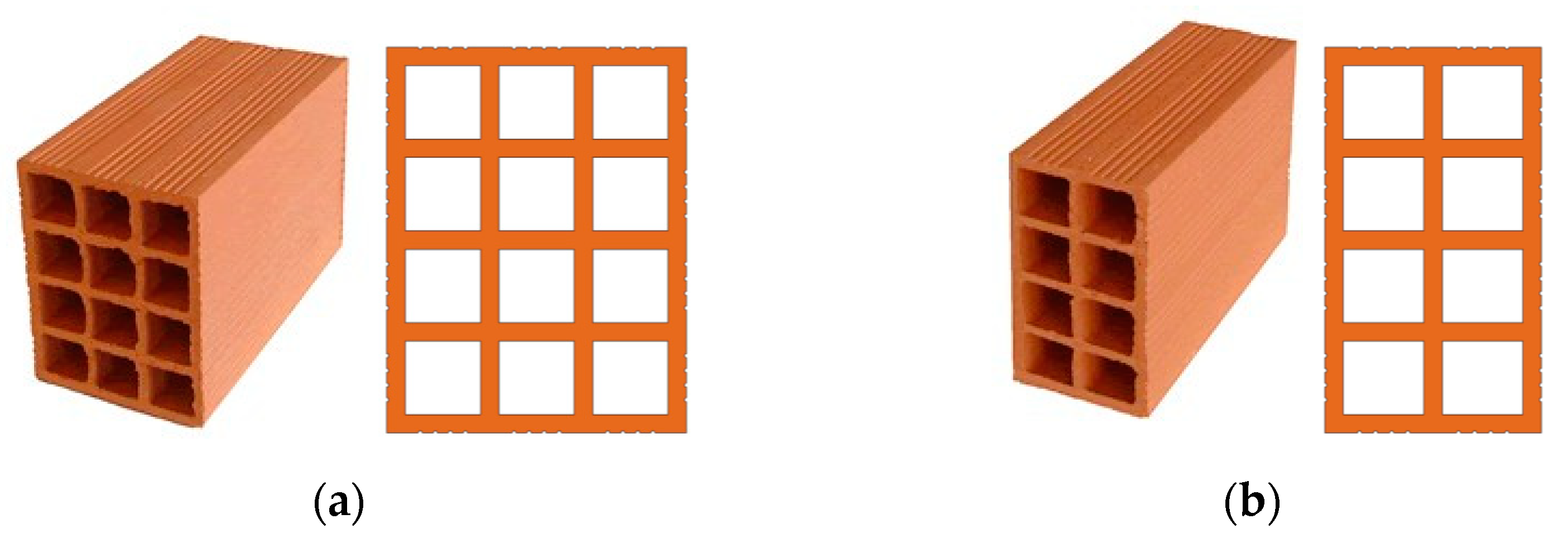
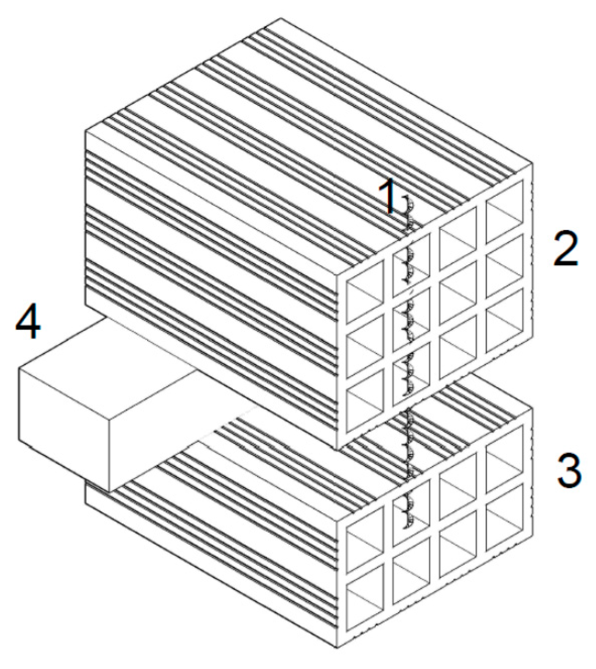
The specimens were built and prepared following an assembly line analogy (depicted in
Figure 6a). The specimen preparation started with the placement of the 30 × 20 × 11 bricks. Secondly, polystyrene bars (XPS), previously prepared, were carefully placed on top of the first layer of bricks (see
Figure 6a and
Figure 7), to simulate the air-gap space between layers. Finally, the specimen has been “closed” with the placement of the 30 × 20 × 15 brick panel. To assure the functioning of the system and the correct application of the post construction wall tie, a set of wood boards and clamps were used to guarantee the stability of the bricks during the drilling process and the application of the solutions.
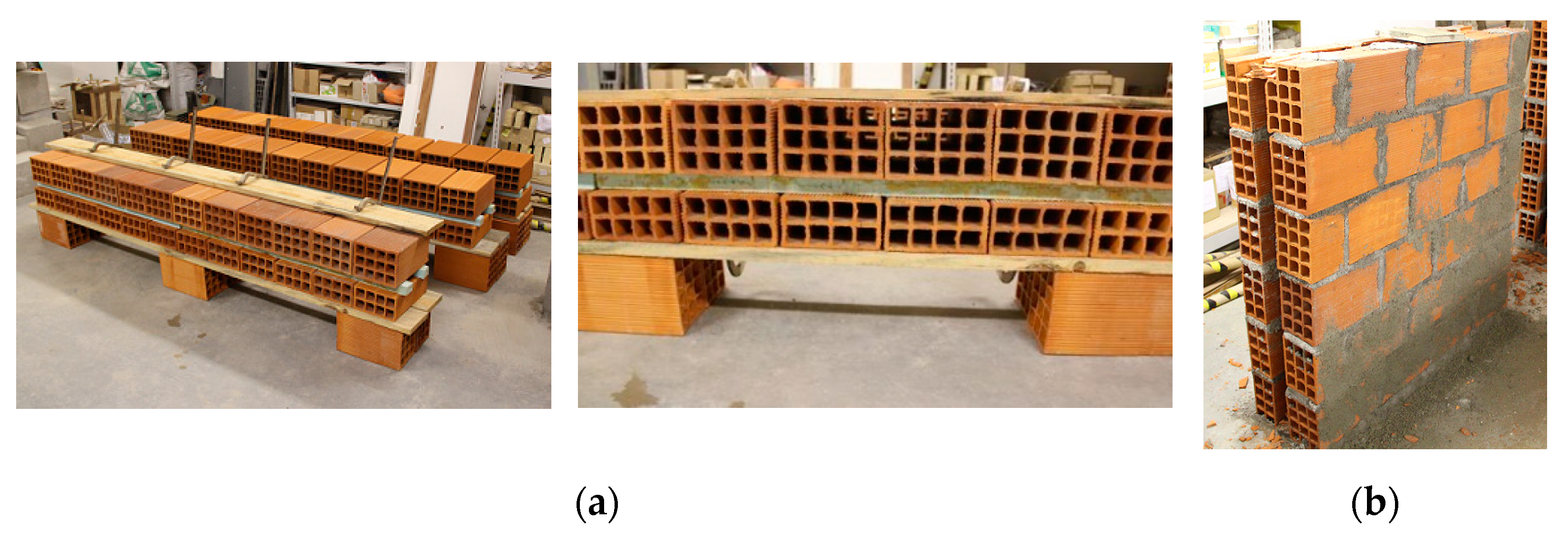
Regarding the four masonry wallettes (see
Figure 6b), their construction followed a similar sequence: (i) preparation of the brick laying mortar; (ii) positioning of the first row of bricks; (iii) pre-wetting of the bricks; (iv) brick laying; (v) filling of the vertical head mortar joints; and (vi) rendering of the masonry wallettes.
5.2. Application of the Post-Construction Wall Tying for Single Isolated Specimens
5.2.1. Solution A
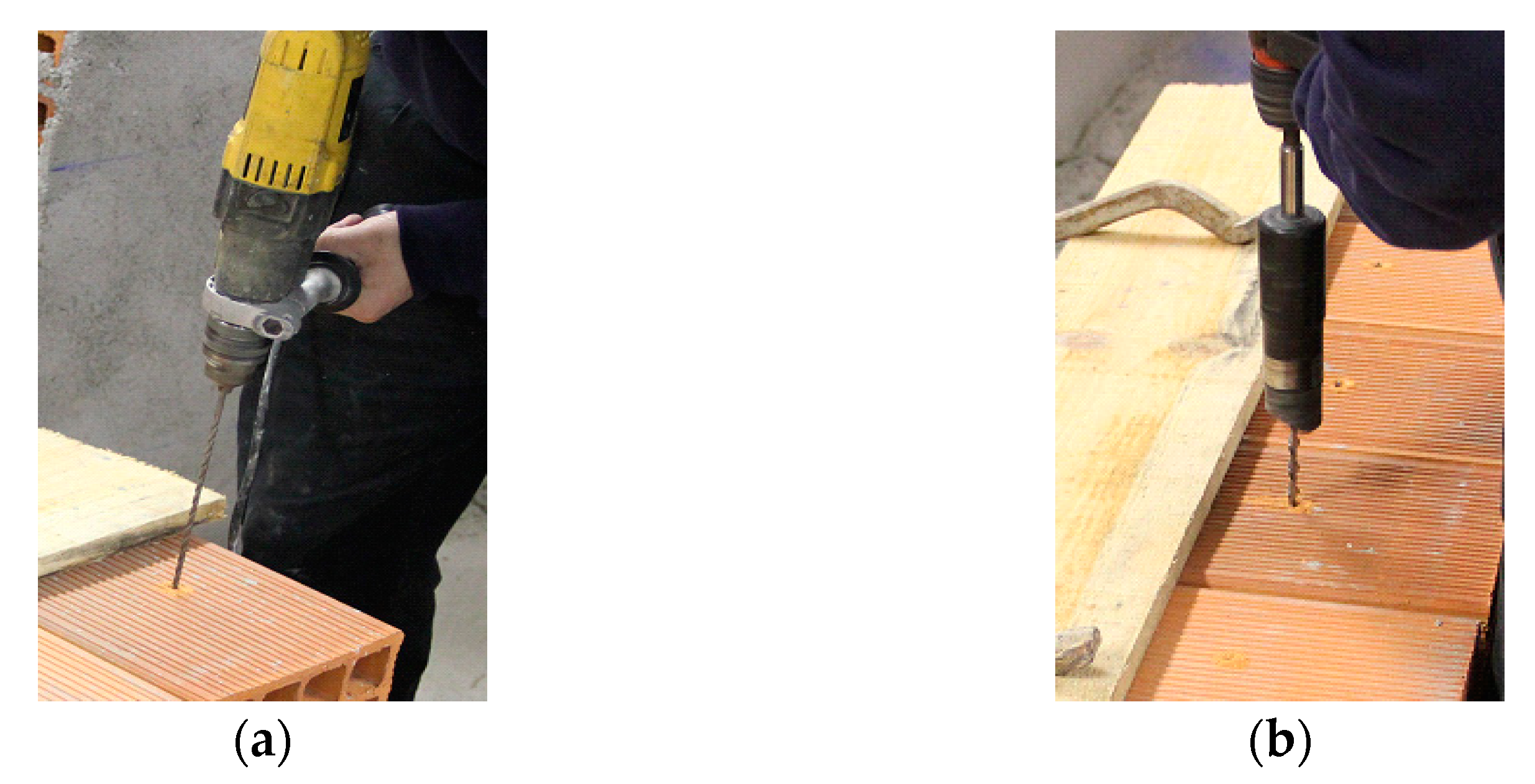
For the application of
Solution A, the used steel tie rods were made of stainless steel with a helical format of 8 mm in diameter. As observable in
Figure 8a, the first step consisted of pre-drilling the bricks resorting to a 5 mm drill. Secondly, the helical tie rods were placed into the pre-drilled holes, as seen
Figure 8b. Regarding this procedure, it is worth mentioning that the insertion of the tie rods have been performed by crimping, i.e., by drilling with pulse, resorting to an adaptor coupled to the drill, specifically for this purpose.
5.2.2. Solution B
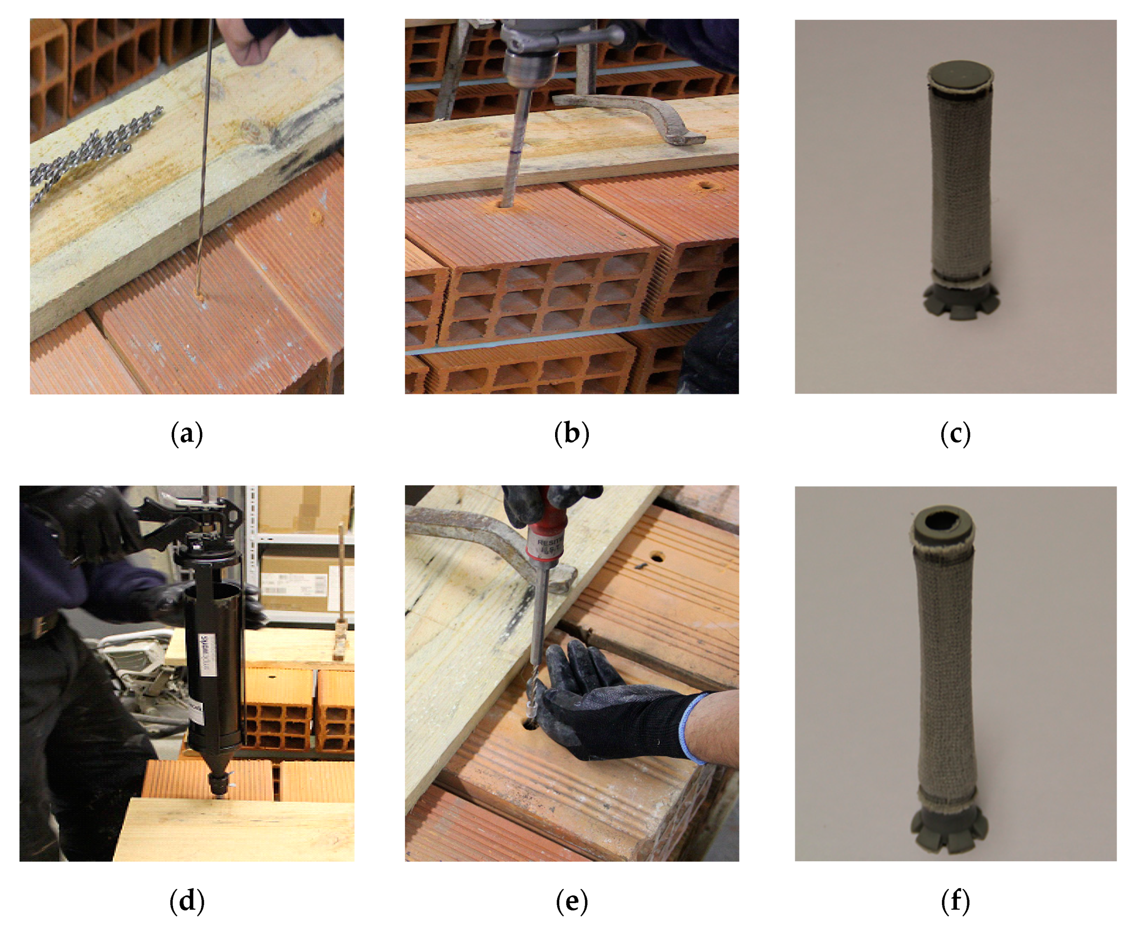
For the application of
Solution B, special care has been taken during the insertion and positioning of the sleeves (either sock or plastic), necessary for the application of the grout. Otherwise, these jacks tend to be placed in an incorrect manner, leading either to the malfunctioning of the grout or making impossible its injection. It is worth noting that the injection is itself a particularly demanding task to perform, since its application has been made with the grout injection nozzle gun positioned vertically, making it difficult to control the grout introduction. Another important aspect that must be considered in this solution is the required curing time of the grout (28 days in the particular case of a cement-based grout). The execution steps followed for the application of
Solution B are presented in
Figure 9.
5.3. Application of Post Remedial Wall Ties on the Masonry Wallettes
The application of post remedial wall ties on the masonry wallettes has followed the same procedure used on the preparation of the isolated specimens. Particular precaution has been taken prior to drilling on the positioning of holes in order to avoid hitting the vertical head mortar joints. Additional concern considered during the implementation of this solution has been to assure that the adequate amount of grout was injected into each sock sleeve, in order to guarantee the formation of a suitable bulb. The shape of the grout bulb formed is independent of the direction of the grout injection. For the sake of comparison, this was verified before defining the first experimental testing procedure, when the injection was done for the two brick specimens (single isolated specimen) in the vertical direction and for the double leaf wall specimen in the horizontal direction. In both cases, the “egg” shaped grout bulb has always been formed because of two reasons: (i) the consistency of the injected grout, that is not excessively fluid; and (ii) the flexible sock that restrains and prevents an irregular shaped bulb from being formed.
5.4. Description of the Pull-Out Tests
For the singular isolated specimens, the helical steel rod has been cut between both bricks (that is, in the air gap existing between the two brick panels), since this testing approach intends to pull-out the steel rods individually. The test has been performed resourcing to a 3 kN dynamometer for precision purposes. Regarding the wallette specimens, aiming to reproduce a real wall in a laboratory environment, they were constructed to test and identify pinning application constraints, limitations, as well as improvement measures for both techniques. For Solution A pull-out tests performed, a 3 kN dynamometer has been used, and for Solution B, a 16 kN dynamometer was used to take advantage of the resolution and precision of the equipment since, in the case of the pull-out tests for Solution B, these exceed the value of 3 kN.
A noteworthy aspect related to the testing set-up is that, in order to inject the grout into the sock sleeve, due to their additional extension, it was necessary to arrange an adapter for placing the injection gun, making it possible to apply the grout within the inner sock sleeve inserted into the 30 × 20 × 15 brick.
5.5. Analysis of the Results Obtained in the First Testing Campaign
5.5.1. Solution A
As previous referred to in
Section 4, all the single brick specimens (including both new and pre-existent bricks) were tested according to the procedure defined in the standard NP EN 771-1 (CEN2006). Following to the methodology described in
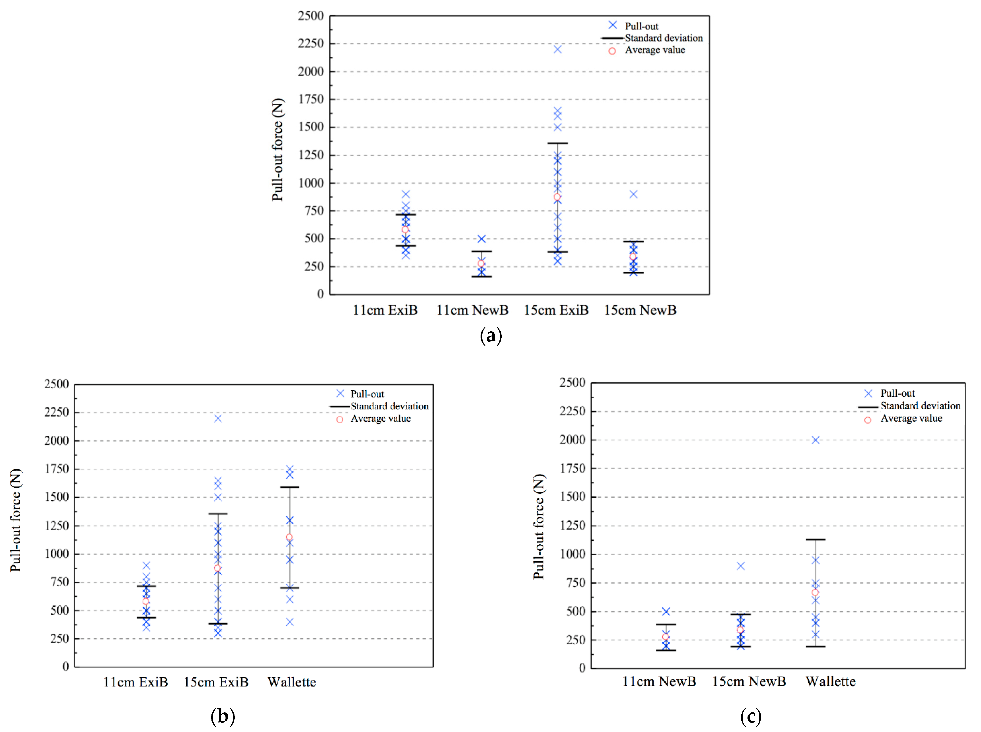
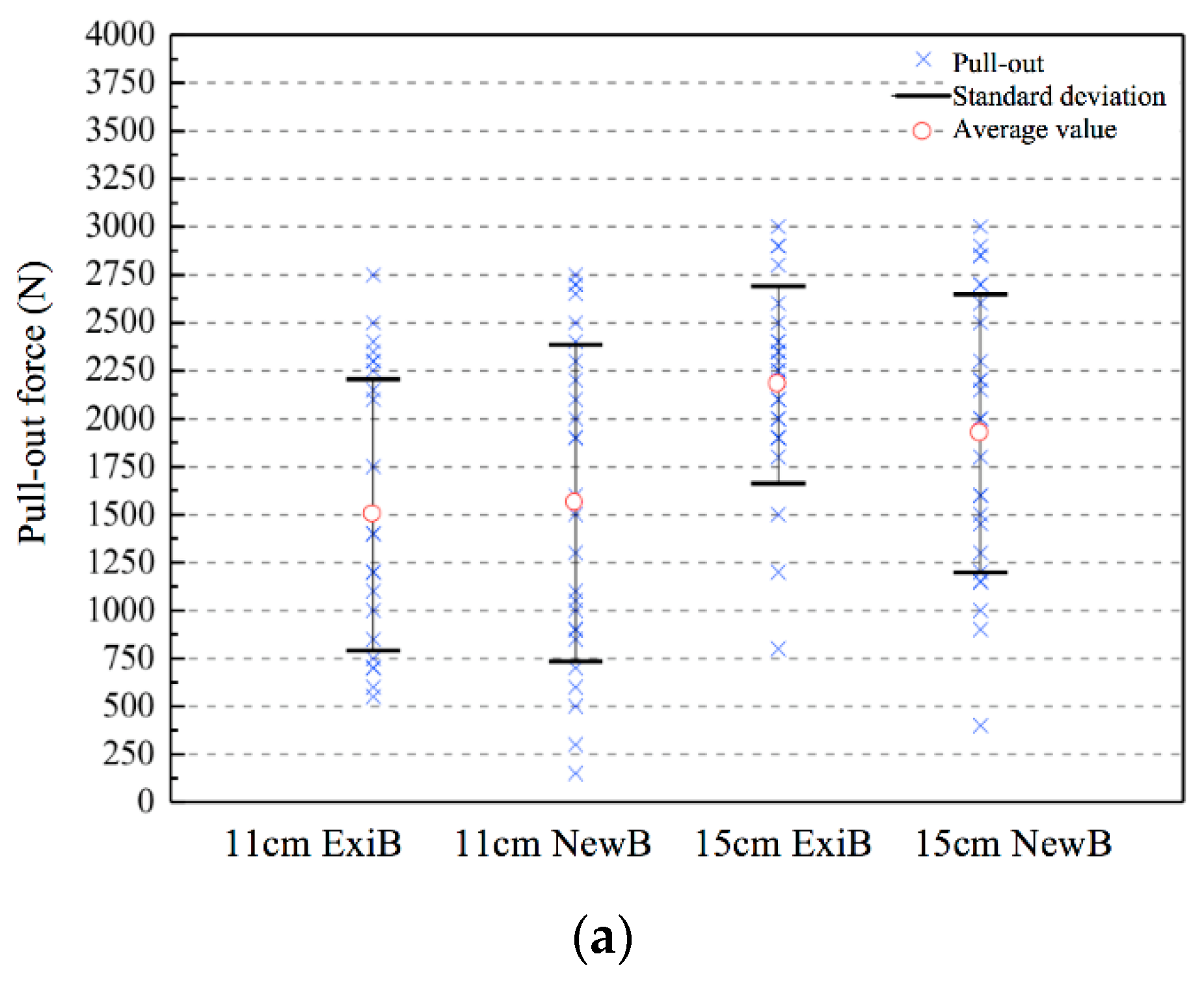
Section 3, the specimens were tested in pull-out and the record of relevant information from the tests, namely, load cell forces were collected and presented in
Figure 10. From the results obtained, it is shown that pre-existent brick specimens (designated in the plots as #cm ExiB, meaning, dimension of the brick type and pre-existent specimen) present, on average, a higher pull-out force in respect to new brick specimens (designated in the plots as #cm NewB, meaning dimension of the brick type and new specimen); and for new and pre-existent specimens of 30 × 20 × 15 brick type format, this force is higher with respect to the 30 × 20 × 11 brick format. Since
Solution A is strictly dependent on frictional force mobilization of the helical steel bar, these results were somehow expectable considering the brick geometry of hollows and web thickness, higher in the case of the 30 × 20 × 15 bricks. When compared with the new specimens, pre-existent bricks present higher compressive strength (indicator of better mechanical behavior), and the thicker value of the webs is also higher, leading therefore to higher pull-out force in both formats. In addition, since brick formats 30 × 20 × 15 have three webs that are pierced, in respect to the two of the 30 × 20 × 11 brick format, higher frictional resistance is expected and consequently the pull-out values for the wider bricks are higher. The result values obtained for the pull-out tests performed in the wallettes were, on average, higher when compared with the obtained results for the single brick specimens.
From the analysis of
Figure 10, it is possible to observe—even though taking into account the difference in the testing methodology for the single brick specimens, for which the pull-out tests are done individually for each brick—that the pull-out force of the 30 × 20 × 15 brick format is 20% to 50% higher than the one of the 30 × 20 × 11 format. Comparing the pull-out forces obtained of the wallette and the 30 × 20 × 15 brick format, an increase between 40% to 95% was attained for the pull-out force in the wallette specimens, proving that the mechanical pinning between bricks is beneficial for this type of horizontally hollowed brick geometry. However, further testing driven to better understand this relationship is encouraged.
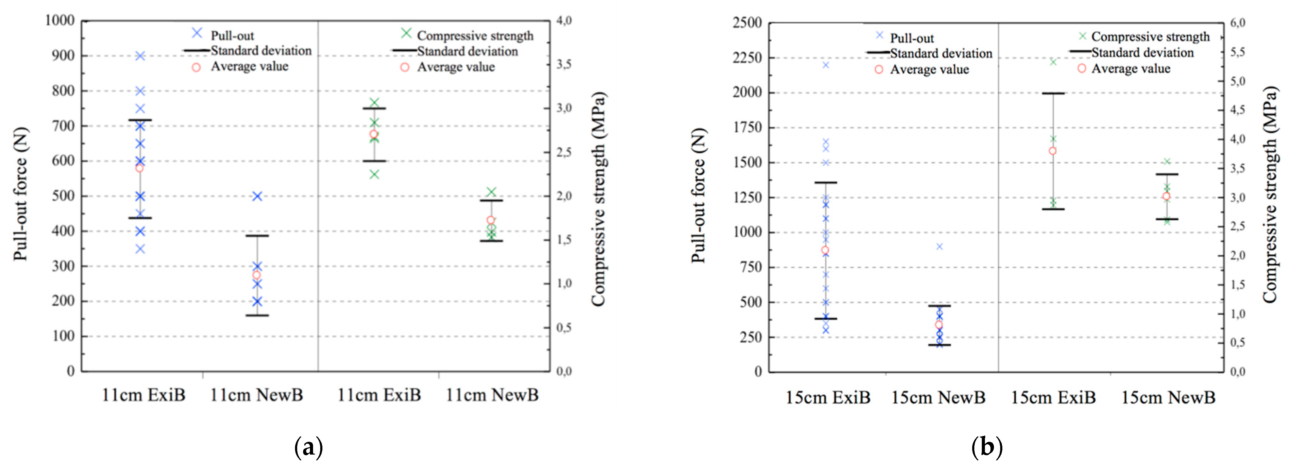
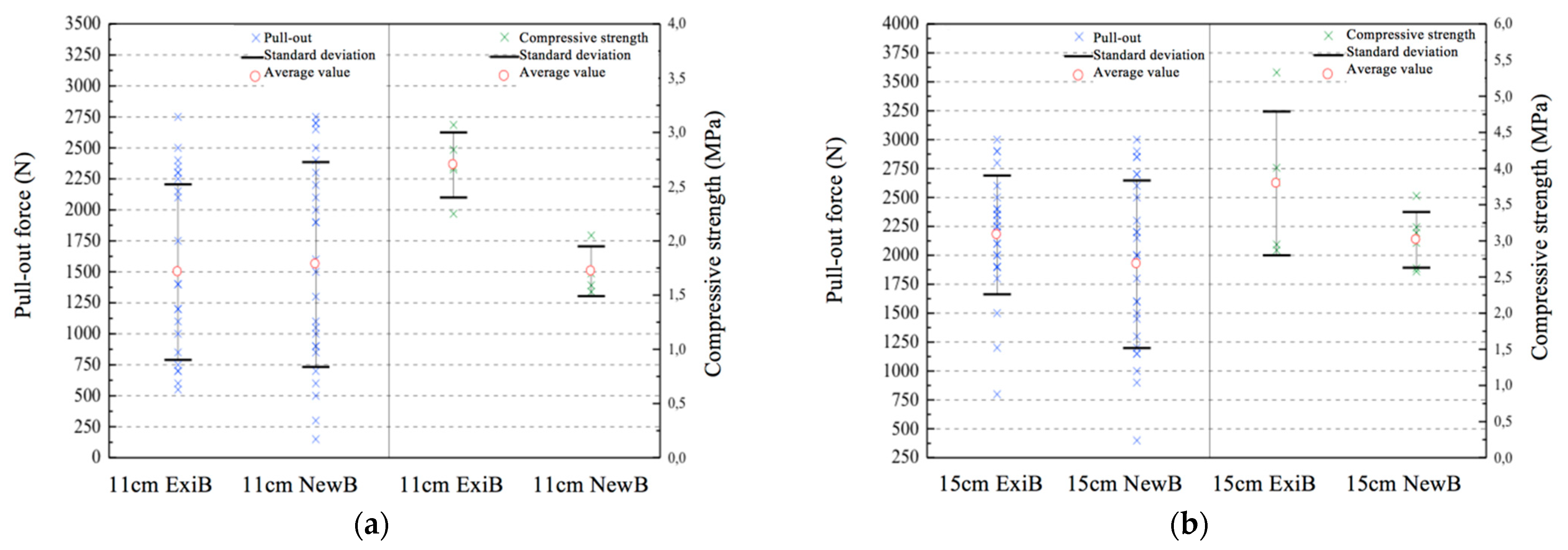
From the analysis of
Figure 11 it is possible to observe that pre-existent bricks specimens present, on average, higher compressive strength, when compared with new brick specimens. Thus, a direct correlation was observed in the attained results (compression and pull-out force), showing the same tendency of higher result values for the existent brick specimens. Finally, regarding the failure mode, all tests revealed that in
Solution A, when applied to the wallettes, failure occurs exclusively by steel tie slippage.
5.5.2. Solution B
As previous referred to in Methodology (see
Section 3), the testing framework and the number of specimens for
Solution B was the same used for
Solution A.
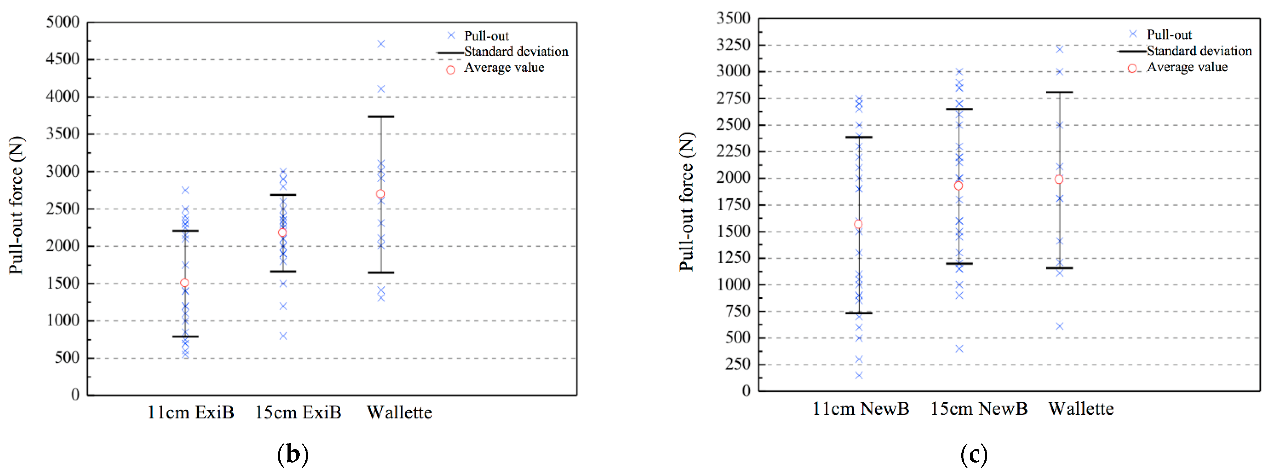
From the analysis of
Figure 12, it is possible to conclude that both new and the pre-existing bricks specimens present higher pull-out force values for the specimens with 30 × 20 × 15. Although the closed-end sock sleeve inserted into the inner leaf of the 30 × 20 × 11 brick may, at first sight, allow a better formation of the grout bulb (due to the assured pressure of the grout injection nozzle gun), its effectively formed contact area between the grout bulb and the web of the brick may still be reduced. Furthermore, the fact that the sock sleeve, inserted into the outer leaf of the 30 × 20 × 15 brick, is opened on both extremities (since the helical steel bar must pass through) and pierces two webs of the brick, may even be positive to the formation of one smaller additional bulb after the first inner web, leading to improved results.
The results obtained for the pull-out tests performed on the wallette specimens (new and pre-existent bricks) are depicted in
Figure 12. The acquired results reveal that the pull-out force of the wallette is about 5% to 15% higher when compared with the force attained for the 30 × 20 × 15 brick specimens.
Regarding the comparison between the compressive strength results with the pull-out forces, as depicted in
Figure 13,
Solution B do not exhibit the same tendency observed in
Solution A, attaining higher values of the pull-out force when the compressive strength is also higher. In this sense, only the 30 × 20 × 15 specimens reveals higher resistance in the pull-out tests when the compressive strength is higher as well. In opposition of
Solution A, this wall tie execution technique strongly depends on other features, such as the grout quality and bulb formation into the hollowed bricks, tie insertion or bond to the grout, and, most importantly, on the quality of the execution, as will be discussed further.
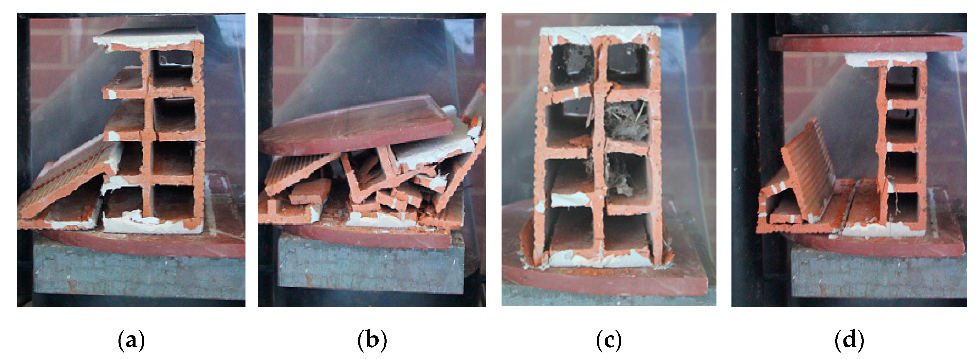
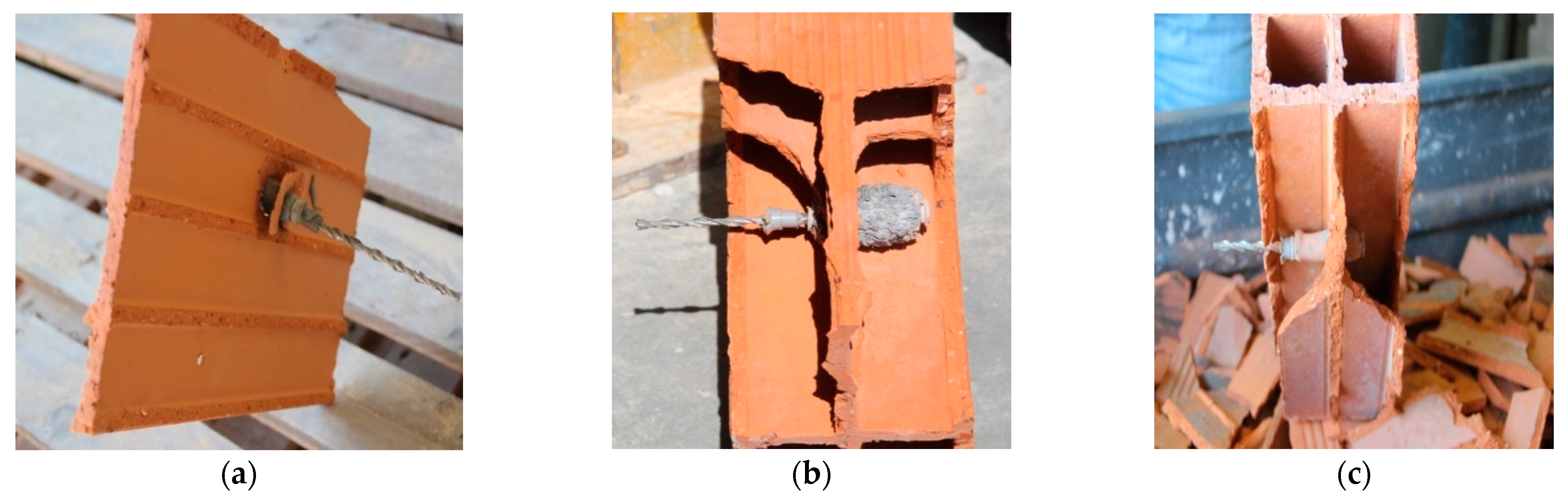
From the pull-out tests performed on the specimens using Solution B, it was possible to identify three types of failure modes:
Fragile failure (FF): this type of failure appears when, during the test, abrupt loss of adhesion occurs between the tie-bar and the brick walls/webs, driven by the loss of strength capacity of the brick to the pull-out force.
Figure 14a presents an example of this failure, conditioned by the brick resistance.
Failure by tie-bar slippage (FTS): this type of failure arises when slippage of the tie-bar occurs within the grout. From
Figure 14b, it is possible to verify that the brick web is intact without attaining the failure, and the sock sleeve is not moved from the initial position.
Global failure (GF): this type of failure occurs when the brick gradually weakens and fails, and the system solution (sleeve plus tie) slides along the brick web. In
Figure 14c, it is observed the slippage of the solution relative to the hollowed brick web. It is also quite noticeable the slipping experienced once the initial position of the sock sleeve nears the right exterior web of the brick.
6. Experimental Campaign: Phase 2
The second phase of the experimental campaign was developed to fully characterize the different failure types as well as the slipping phenomena attained in the previously phase of the experimental campaign. This second phase comprises 24 tests performed in isolated specimens from
Solution B using new and pre-existent bricks. It is noteworthy that the preparation of the specimens and the application of the reinforcement wall tie solution have followed the procedure adopted for the first phase of the experimental campaign, previously described in
Section 3 and
Section 5.
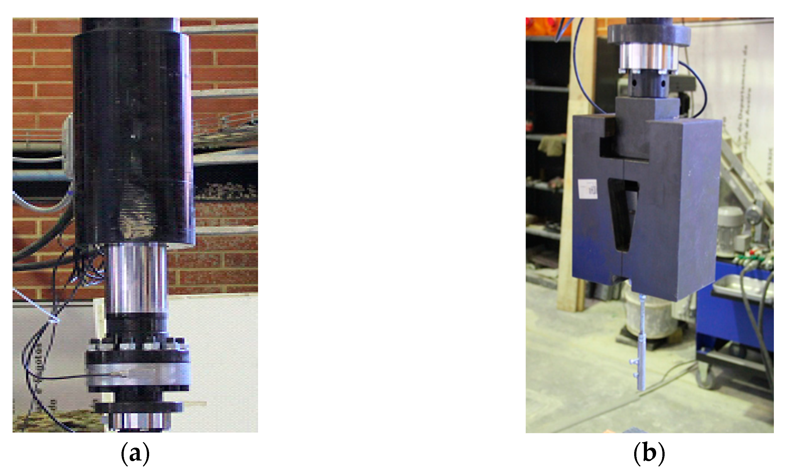
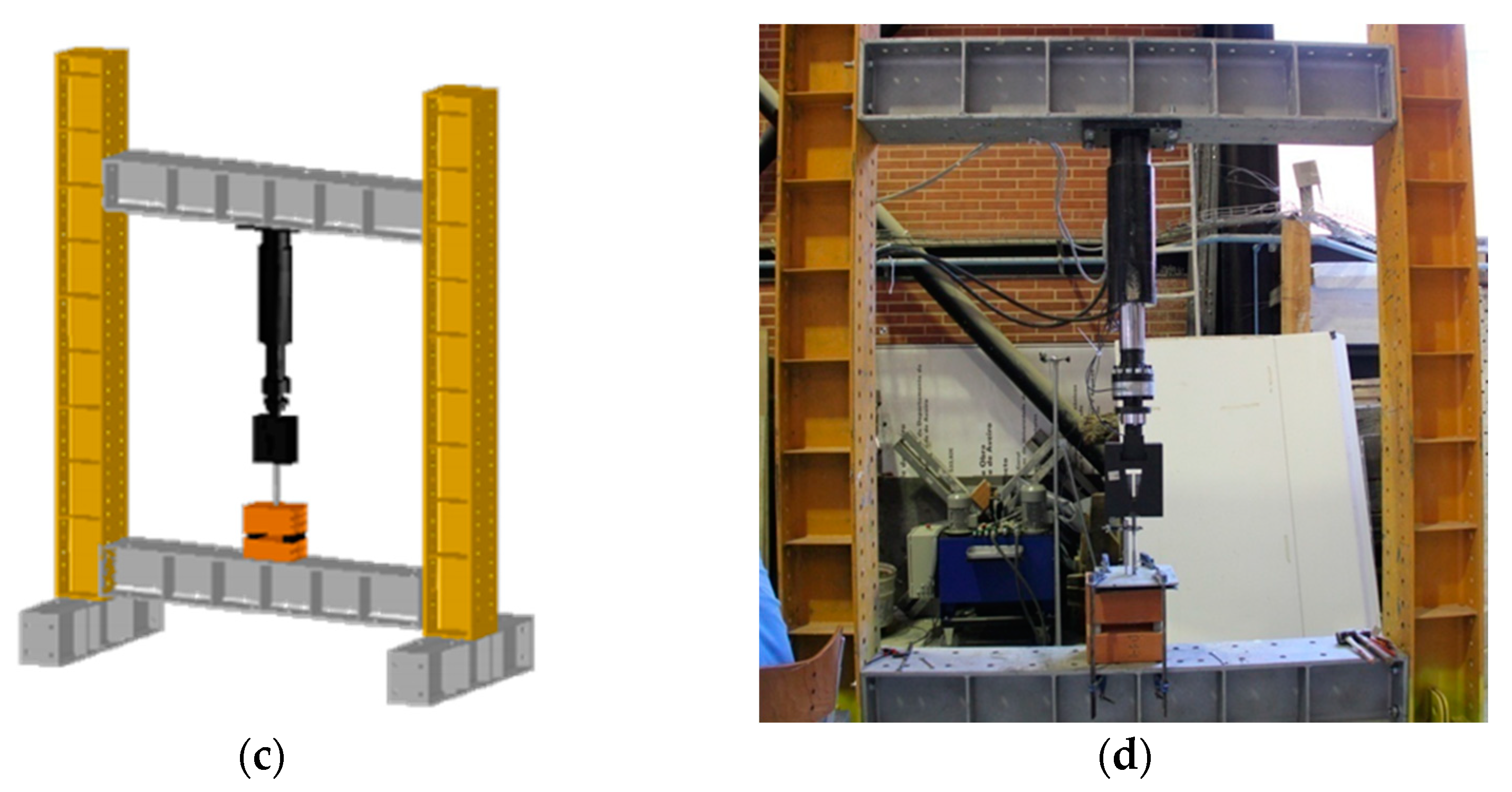
Regarding the pull-out tests, this second phase was performed with a different experimental setup, consisting of the use of a hydraulic jack of 300 kN, fixed to a steel frame coupled to a load cell with capacity of 25 kN in traction and compression (see
Figure 15) that has been used to perform the experimental tests. At the top of the load cell, a steel grip was placed to clamp the steel helical tie (see
Figure 15b). The specimens were constrained by a steel sheet fixed in the outer corners to the lower beam of the steel frame setup (
Figure 15d).
At this experimental campaign, the tests were performed with the two bricks connected by the tie (see
Figure 7). Thus, it allowed to attain the value of the pull-out strength of the entire solution. Finally, the tests were performed at a constant speed with a rate of 0.2 mm/s controlled by the displacement transducer of the hydraulic jack.
Based on the obtained results, individual plots (i.e., by specimen) of the pull-out strength vs. displacement recordings were generated considering the registered behavior in terms of strength evolution, slipping and global displacement.
Table 3 presents the behaviors registered for three groups of new brick specimens tested (a representative test was chosen as example for each group of tests and it is depicted in the plot), whereas
Table 4 presents the result for the two groups of pre-existent brick specimens.
In summary, and regarding the tests performed on new brick specimens, it has been possible to identify three types of failure modes:
Failure by tie slippage (FTS): approximately constant pull-out force during the test, and abrupt decrease in strength in the rupture;
Global failure (GF): the variation of the pull-out force during the test clearly indicates the instant when yielding occurs at each web of the bricks;
Fragile failure (FF): after the maximum value of the pull-out force is attained and yielding occurs, the specimen no longer has the capacity to attain pull-out strength values similar to the maximum peak of strength.
In summary, it was possible to identify two types of failure modes for the pre-existent brick specimens:
Failure by tie slippage (FTS): as in the previous group of new brick specimens, this type of failure was obtained;
Brittle failure (BF): the pull-out force does not reach values higher than the maximum previously obtained.
Regarding the quality control, as stated above in
Section 5.2.2, special attention should be given to the grout injection process, as it strongly influences the effectiveness of the solution. However, there are other parameters presented to control, such as the grout workability time and preparation, which should have an adequate fluidity so that it can be easily injected in the sock sleeve. Another important factor that must be adequately controlled is the drilling process, which requires a careful execution to avoid undesirable damages in the bricks as well as to avoid undermining the steps to be carried out afterwards. Thus, a perpendicular drilling stance is mandatory to allow the introduction of the sock sleeves avoiding extra damages to the specimens. It is also important to control the drilling depth, since it is necessary to preserve the last web of the brick of the internal leaf (usually concerning the 30 × 20 × 11 brick format in the case of a double-leaf wall).
Regarding the execution of the sock sleeves strengthening technique piercing the brick, it should also be thoroughly controlled, since the risk of tearing the sock sleeves when passing through the webs or becoming deformed is possible.
7. Conclusions
This paper focused on the effectiveness of two different remedial wall ties retrofitting techniques with the purpose of tackling a recurrent problem concerning the instability of double-leaf masonry enclosure walls.
The potential advantages offered by the two studied solutions have proven the suitability and reliability of these retrofitting techniques to connect both wall leafs effectively, thus contributing to the global resistance of the existent wall solution against horizontal actions. Due to frequent deficient support conditions of the external envelope layer, the need of adequate connection between the two masonry wall leafs is crucial to mitigate the risk of collapse due to excessive deformation or seismic actions, ultimately compromising human life [
31,
32].
The work comprised an experimental campaign divided into two phases, preceded by the geometric and mechanical characterization of the horizontally hollowed clay bricks (30 × 20 × 15 and 30 × 20 × 11, new and pre-existent aged bricks) used throughout the study. To characterize the effectiveness of the remedial wall tie solutions, a total of 120 isolated specimens and 4 wallettes were executed and tested by performing the pull-out technique. Two different retrofit scenarios have been tested and compared, analyzing two solutions. Solution A is a based on the insertion of a remedial helicoidal tie that is inserted through percussion and connects the two wall leafs solely by friction. Solution B is based on the insertion of cement grout sock that constitutes an anchoring bulb on the extremities of the remedial wall tie.
From the attained results from Phase 1 of the experimental campaign, it is possible to conclude that pre-existent bricks specimens present higher compressive strength as well as pull-out force, when compared with new brick ones, revealing a direct correlation. Regarding the failure modes, all tests revealed that in Solution A, when applied to the wallettes, the failure occurs exclusively by steel tie slippage.
The technique of Solution B is strongly dependent on the grout quality and bulb formation into the hollowed bricks, tie insertion or bond to the grout, and on the quality of the execution.
The second phase of the experimental campaign revealed that no coherent rupture type was attained. In this sense, three different types of rupture have been observed, namely “failure by tie slippage” characterized by a constant value for pull-out force followed by an abrupt decrease in strength; “global failure,” in which the pull-out test behavior reveals a swing of the applied force, until the rupture occurs; and “fragile failure,” where after the maximum value of the pull-out force is attained and yielding occurs, the specimen no longer has the capacity to attain pull-out strength values similar to the maximum peak of strength. This research has opened the discussion on various levels, starting from the need to rethink the technology and execution rules of facades and development of execution guidelines, especially in the cases of veneer wall solutions and erection of infill walls in seismic prone areas, as well as in the case of retrofitting to lead the way to the development of optimization these retrofitting approaches in terms of intervention cost-technical benefit.

 ,
, 


