Computer Aided Assembly of Buildings


Faculty of Civil Engineering, Mechanics and Petrochemistry, Warsaw University of Technology, 00-661 Warszawa, Poland
*
Author to whom correspondence should be addressed.
Buildings 2020, 10(2), 28; https://doi.org/10.3390/buildings10020028
Submission received: 30 December 2019
/
Revised: 5 February 2020
/
Accepted: 11 February 2020
/
Published: 13 February 2020
(This article belongs to the Special Issue Architecture and Engineering: the Challenges - Trends - Achievements)
Abstract
:This article presents an interactive method of computer-aided assembly planning. It is estimated that such planning will be more and more desirable due to the increasing use of prefabrication in construction. Prefabrication meets the trends of sustainable development and digitization as it enables the application of intelligent control systems at the stage of highly specialized production, assembly and facility maintenance. The presented planning method is based on the Monte Carlo simulations and logical algorithms for assembly work planning. It was determined on the basis of the literature studied and our own observations. The paper introduces a detailed model of assembly works planning and is an example of using a computer application developed on the basis of the described model. The example confirms the correctness of the algorithm and indicates its usefulness in the scope of analyzing many decision variants. Further research on labor productivity rates for assembly works, implementation of digital databases of assembly machines and prefabricated elements, as well as integration of the proposed application with the BIM environment should make it easier to commercialize the developed application.
1. Introduction
The construction industry is always changing and evolving. There are some trends and aims that are noticeable in this development. Sustainable construction is one of them. This is a set of activities subordinated to the requirements of sustainable development—a process aimed at satisfying the needs of the present generation in a way that allows the same generations to pursue the next generations. The construction industry is strongly associated with the concept of sustainable development as its impact on the environment is huge. According to the idea of sustainable construction, the life cycle of a building should comply with the requirements of sustainable development.
One of the important measures of sustainability in construction is the amount of energy used in construction. There are three types of energy use in the construction performance: embodied, operational and transformation (utilization) energy. All of them should be minimized through appropriate spatial, construction, material, technological, functional and organizational solutions.
A promising response to the needs of the imminent challenges of sustainability in construction is prefabrication. This technology fits very well in the economic, quality and social criteria of sustainability, and does not set limitations on the architectural form. From the point of view of the common interests of present and future generations, prefabricated constructions usually enable the improvement to a high-energy efficiency of the building, and compared to the on-site constructions, emit fewer pollutants at the production stage. Prefabrication also gives specific restrictions on energy consumption for building and demolishing facilities. It increases in importance because about 50% of all the materials utilized are materials used in construction.
Prefabrication technology offers many development opportunities arising from the automation of production and construction processes. It can be strongly influenced by 5G and IoT (Internet of Things) technology development. Intelligent construction facilities require standardization and standardized solutions to be implemented in a highly specialized construction production.
There is a good chance that prefabrication will only be a key technology for the sustainable construction if the innovative techniques of assembly works planning are developed. Such techniques should involve assembly automation, digital models of construction and planning data.
Digitized information on both the construction site and machines used for the assembly, as well as construction elements to be mounted, simplify effective construction planning. The work of many assembly machines should be planned so that their effective utilization on site is taken into account, which is a partial goal of sustainable construction.
There is therefore a need for a computer-assisted planning method that enables the planner (scheduler) to search for energy-optimal technological and organizational solutions, especially if the work of many assembly machines is required.
In the literature, a variety of solutions to problems associated with the operation of cranes in the assembly planning can be found. A fast development in the methods applied to solve assembly planning problems has its beginning in the 1980s and it was associated with the dynamic growth in construction (including prefabrication) and construction equipment. However, work on these methods was triggered by the development of information technology, which is supposed to be a key tool to improve all technical and organizational systems.
One of the originators of improving the organization of assembly works were, among others, Gray and Little, Furusaka, Warszawski, Peled, Van Dijk, Van Gassel and Schaefer [1,2,3,4,5]. Their models of supporting the selection of crane’s size were related to the cost of crane’s work, and among the others, involved expert systems.
A number of applications that support assembly works planning are based on graphic methods and enable the selection of the size of the crane [6,7,8] or even a group of tower cranes [9] required for the particular location. The more advanced tools worked as crane operation simulators [10], which selected the size of the crane and the type of slings [11] required, or estimated the costs and time of work. The presented methods, however, do not offer the possibility of optimizing the cranes’ operation. It applies to both commercial applications that can be used in order to select the type and location of the lifting device [12,13] and advanced non-commercial applications that are still valid today [14,15,16]. This type of application works well when planning the organization of the construction site and assembly of heavy-weight units. Other applications, usually available as plug-ins for the CAD software, enable assembly works planning, as well as their subsequent simulation that helps to eliminate potential collisions. In summary, contemporary computer aided assembly planning is usually limited to checking the possibility of mounting the load by the selected crane. It does not provide scheduling, assembly cost estimation, hardly ever compares individual assembly situations with each other, and does not provide tools for optimization of assembly works.
The problems of crane selection were discussed in Reference [17] where the fuzzy logic theory was used, in Reference [18] where neural networks were involved, and in Reference [19] where genetic algorithms were used to select the type of crane. The important role of soft factors in the crane selection problem and a procedure for crane selection in relation to these factors was presented in Reference [20]. In turn, Reference [21] proposes the AHP method (analytic hierarchy process) to analyze crane type selection and takes into account both hard and soft factors. In each case, the problem boiled down to the problem of the lifting device selection, which does not meet the current needs of work planning where a variety of assembly machines are used.
An original crane planning system was developed in References [22,23,24], where, based on the weight of the mounted elements, reach and lifting height, and using the defined databases, the required crane sizes and locations are determined. The final result is an assembly plan that excludes collisions between cranes. However, this system is dedicated to monolithic works as it analyses tower cranes only. Similarly, in Reference [25], the crane optimization problem was mathematically formulated as an NP-complete problem and was solved as the TSP problem (traveling salesman problem). However, it is also dedicated to monolithic works, where one machine supports several assembly brigades.
A significant contribution to the development of methods that support assembly planning was made by researchers from the Faculty of Engineering of the University of Alberta in Edmonton, Canada [26,27,28,29]. They proposed, in Reference [30], a method that incorporates object information modeling (BIM) and external databases to plan mobile crane positions and react to changes in the project site layout during modular structure assembly in the extraction of crude oil from the oil sands.
With the above in mind, worldwide literature presents advanced knowledge and proposes various ways to solve decision problems related to construction work planning. In most cases, the proposed solutions relate to selected planning issues, without a comprehensive approach to assembly planning as a whole. This is why the advanced support systems cannot be applied to assembly works directly. The modern method of planning assembly works should then present comprehensive solutions that combine the problem of crane selection, their size, number or location, take into account the assembly of each element together with the assembly schedule, time and cost of works and the optimization of these variables. All these issues are incorporated into the proposed method of assembly works planning.
2. The Proposed Method of Assembly Works Planning
2.1. Prefeace
The main problems in assembly works planning focus on the selection of cranes, their number and locations. The complexity of organizational dilemmas occurring at the initial stage of planning and during assembly works indicate that simulation methods are advisable to solve the assembly planning problems. In the proposed model, the Monte Carlo method and logical algorithms based on observational studies related to assembly works are used.
The main purpose of the article is to present a method of assembly works planning, which focuses on the simulation of assembly works over time. The planning process is run with the interaction of the planner, who controls the planning attempts, defines constraints (i.e., on resources) and decides on the final solution. A similar simulation approach to works planning was presented in Reference [31], where an interactive simulation was applied to plan concrete works and formwork utilization.
The assembly planning method has been algorithmized and pre-programmed in order to check its correctness. The application’s effectiveness has been confirmed by simulations run for a real assembly works of the office building.
2.2. Model of Planning Assembly Works
Lets consider the set of prefabricated elements , and their characteristics defined by the matrix , where:
- la,1—stands for the weight of the a-th element, in tons,
- la,2—stands for the maximum width of the a-th element, in meters,
- la,3—stands for the maximum length of the a-th element, in meters,
- la,4—stands for the maximum height of the a-th element, in meters,
- la,5—stands for the duration of loading the a-th element, in minutes,
- la,6—stands for the duration of assembly of the a-th element, in minutes,
- la,7—stands for the shape coefficient for the a-th element,
- la,8—stands for the required date and time of delivery of the a-th element,
- la,9—stands for the weight of the sling used in the assembly of the a-th element, in tons,
- la,10—stands for the height of the sling used in the assembly of the a-th element, in meters,
- la,11—is the a-th element location-coordinate x,
- la,12—is the a-th element location-coordinate y,
- la,13—is the a-th element location-coordinate z.
For the assembly of prefabricated elements, various types of assembly machines can be used. They are divided into two sets: a set of stationary machines (which do not change their location throughout the assembly works) and mobile machines (which change their location if necessary) Possible locations of assembly machines (coordinates in a flat coordinate system) create the set for stationary machines and the set for mobile machines.
To start the assembly cycle, it is necessary to define: the number of planning attempts (which are also the number of assembly planning solutions, IL, start and end times of work of the assembly teams <TSTART,W, TEND,W> and to set the priority for stationary machines. When the priority of stationary machines is applied, the construction components will be assigned to stationary machines first, and only if there is no technical possibility of assembly, mobile machines will be considered. Such a solution allows for a better utilization of stationary cranes, with a unit cost of work that is usually lower, and has breakdowns that cause less loss due to their underutilization. In addition, such an approach reduces the work of more expensive mobile cranes, which, if the breakdown is long enough, can be used in other project (or task) performances. If the priority of stationary cranes is not applied, the algorithm assigns the subsequent a-th construction element to the crane, without taking into account the mobility aspect.
The start of the simulation procedure initiates the determination of the next k-th solution number . For each rk solution, the number of stationary cranes (n) is drawn from the set Mst and the number of mobile ones (o) is drawn from the set Mnst. The variables have a value of at least 0, and at most, C for stationary machines, , and at least 0, and at most, D for mobile machines . The number of randomly selected stationary cranes is further limited by their number of possible locations. This condition does not apply to mobile machines, which have locations that may change. The draw begins with a value of 0, so the cranes can be selected from both sets of stationary and mobile machines. For each solution, rk is the random order of stationary and/or the mobile machine is drawn. In each k-th planning simulation, they form a set and Each c-th stationary crane is assigned to the e-th location, and for every d-th mobile crane, the f-th location is assigned. If the number of stationary cranes n and mobile cranes o is greater than the number of their potential locations, E and F, respectively, crane assignment to their location ends with the last free place or . Other stationary cranes will not be used in the k-th simulation run, while mobile cranes may be used if there is no technical possibility of assembly of the a-th element by any cranes in their assumed locations. It brings about the need to search for the f-th location of the d-th crane. In each of the k simulation runs, sets of assembly machines can be described with the function as below. The argument of this function is the crane’s location:
The planning goal is to specify, in each simulation, the work plan for assembly machines and that minimizes the cost of assembly operations for the elements defined by the set Q and matrix as well to minimize the duration of works and the number of unmounted elements. If there is no technical possibility of assembly of the a-th element, either by crane or crane , from their locations available in the k-th simulation run, the element is labelled unmounted. The inability to mount a few or a dozen of elements does not discredit the solution. If the cost and duration of the task are acceptable, the planner should accept it and assume that the unmounted elements will be assembled individually. The number of unmounted elements indicate the quality of solutions and can be a guide to better assembly planning. The described above decision situation is presented in Figure 1.
The following assumptions are made:
- the sets of available cranes Mst and Mnst as well as their locations and are finite and can be modified before assembly planning (before simulation);
- In each simulation k, the deadline for the a-th element assembly is one that results from the crane selection. The crane that is being considered is the crane that finished work the earliest and is sought at the time when the assembly of a preceding (a-1) element or element labelled as unmounted ends;
- If the assembly date (as described above) is ahead of an actual delivery date, it should be set on the date of delivery. Therefore, if delivery dates are defined as the prefabricated elements’ characteristics, the assembly is being planned in correlation with their delivery. If the delivery dates correspond at most to the assembly commencement date, this issue is not taken into account.
In order to differentiate solutions within the priority of stationary cranes, the B set, which may include stationary cranes Mst or both types of cranes, Mst and Mnst, is created.
If there is no technical possibility of assembling the a-th element by the c-th stationary crane from the e-th position (and if the priority of stationary machines is not applied-also by the d-th crane from the f-th position), the algorithm attempts to find the d-th mobile crane in the f-th location (if the priority of stationary machines was set).
If a crane capable of assembling the a-th element still has not been found, the simulator checks (in the order that results from the initial ordering) every d-th mobile crane in each possible location f, starting from the first crane and the first defined location f. If a proper crane is found, the duration of the a-th element assembly is increased by the duration of the d-th crane transfer to the f-th location. At the same time, the assignment of mobile cranes to their locations is updated.
The cranes’ working times are calculated periodically and take into account normal daily breaks. Every j-th day of the assembly brigade’s work starts at TSTART,W. If the assembly completion time for each construction element exceeds the assembly completion time of the brigade (TEND,W), the assembly deadline is set on the next day for the assembly (TSTART,W).
The planning task boils down to setting assembly schedules, which take into account a cranes cyclic work. The type, size, number and placement of cranes affect the costs, time and efficiency of the assembly operations. It is expressed in the number of unmounted construction elements.
Deriving an optimal solution requires a large number of planning tests in which the number and locations of cranes are changing. The problem can be solved through simulations. The cranes’ numbers, ordering and locations may be drawn randomly. For each draw, the characteristic schedules and costs of cranes’ work are forecasted. The number of schedules is, in turn, equal to the number of expected solutions (IL), which are determined by the planner. The planner is the one who selects the number and size of the cranes and indicates their potential locations. The simulator is a planning tool that presents different time and cost solutions and the number of unmounted construction elements.
For each simulation k, the planning procedure begins with the selection of c-th stationary crane from the Bk set (if the priority of stationary cranes is set) or the crane from the group of c-th stationary cranes and d-th mobile cranes (in the priority is not set). Only the cranes that finished their work at the given moment “*” shall be considered.
If there are cranes that have finished their work within the same deadline, the order of their work is determined based on ordering on the list of stationary cranes (if the priority is set), or list of all machines together and ) (if the priority is not applied). It requires a temporary crane to be defined. It is a crane that has completed its operation at the earliest among the dynamically changing crane base:
where is the date of assembly completion for the c-th stationary crane in e-th location in the k-th simulation.
Formula (2) does not allow for an unambiguous choice when at least two assembly machines have finished their work at the same time. It happens at the beginning of the assembly works. Therefore, it is necessary to search for the crane that has finished its work the earliest and has the lowest number in the set, according to the relationship:
Thus, as the first at the moment, the c-th stationary crane will finish its work. If in the Bk set also contains mobile cranes , then Formulas (2) and (3) take the form:
where is the date of assembly completion for the d-th mobile crane in the f-th location in the k-th simulation.
In this case, the crane that will finish its work first at the given moment will be the c-th stationary crane or the d-th mobile crane, respectively, .
However, if the selection is only made from a group of mobile cranes, Formulas (2) and (3) take the following form:
It happens if the priority of stationary cranes is set and if there is no possibility of assembling the a-th element by stationary cranes.
It is verified in the next step, whether it is possible to assemble the a-th element by the selected crane or from the location or . It is done by checking the minimum required load capacity, as well as the minimum reach and lift height in this location . The assembly is possible if the lifting capacity of the c-th or d-th crane is at least equal to the minimum load capacity required at a reach equal to and a lifting height equal to according to the following relationships:
where is the load capacity of c-th stationary crane in e-th location at a reach equal to and a lifting height equal to .
is the load capacity of the d-th mobile crane in f-th location at a reach equal to and a lifting height equal to .
There are different types of cranes that may require a different approach to the collision check. Moreover, the checking procedure is frequently repeated. This is why the calculation block has been distinguished as a separate “collision checking procedure”.
Verifying the assembly possibilities for a tower crane is not a problem. In the case of a mobile crane, it is necessary to check additional conditions that result from the possible collisions between the boom and the construction or the assembled element. The checking procedure in such case is described in References [32,33].
If the assembly is technically impossible, the temporary crane is removed from the set Bk, lub . This operation is repeated until an appropriate crane is found or until the set is empty, .
If the set Bk is empty and it had contained only stationary cranes , (the priority of stationary cranes was set) and there are unmounted construction elements, the supplementation of set Bk with mobile cranes, begins. The first available machine is then selected again according to Formulas (6) and (7).
As before, if there is a possibility of assembly according to Formula (9), the selected d-th crane ) is temporarily removed from the set Bk. The operation is repeated until an appropriate crane is found or until the set is empty, Bk = ∅.
If none of the stationary cranes , as well as mobile cranes , from the assigned locations are able to assemble the a-th element, the algorithm, for a d-th mobile crane (), searches for a location , , in which the assembly conditions are met. If such a crane exists and it is the d-th crane at the f-th location , its location changes into . The assembly duration for the a-th element is then increased by the duration of a possible crane disassembly and transfer from the current to the new location:
where is the a-th element assembly duration increased by the duration of a mobile crane assembly at the f-th location.
- is the time required to assemble the d-th crane at its location.
- is the time required for disassembly and departure of the d-th crane from its location.
However, if at the f-th location, the d-th crane was located, it is disassembled now and removed from this location. This crane is held ready to assembly subsequent elements from the other locations. The time of work of this crane is increased by the duration of disassembly from the f-th location:
At the same time, the f-th location is left by the d-th crane and replaced by the d-th crane , which capable of assembling the a-th element:
In each of the above cases, if it is possible to assemble the a-th element qa by the c-th stationary crane or the d-th mobile crane (in each k-th simulation), then the assembly duration of the a-th element should be added to the crane’s working time. If the assembly time exceeds the assembly brigade’s end time, the assembly should be scheduled for the next j-th day of work. The date of assembly commencement results from the completion of work by the c-th or d-th crane or it is the date of delivery of the a-th element to the construction site. For stationary cranes, the deadline for assembly completion by the c-th crane, on the j-th day of work, in the k-th simulation and at a given moment “*” should be calculated from the formula:
where
- is deadline for the assembly of the element that precedes the a-th element.
- is the time (in hours) when the assembly teams start their work on day j + 1.
In the case of mobile cranes, the deadline assembly completion by the d-th crane, on the j-th day of work, in the k-th simulation and at a given moment “*” should be calculated from the formula:
If the a-th element cannot be mounted by either the c-th stationary crane from the e-th location or the d-th mobile crane from the f-th location, the element remains unmounted and the assembly procedure for the next element begins:
where
- is a set of elements unmounted during the k-th simulation.
The procedure described above is repeated until all the prefabricated elements are mounted or until it is proven that some elements technically cannot be mounted. For each k-th simulation and its solution, the following data are remembered:
- cost of the assembly operations,
- duration of the assembly tasks,
- the assembly schedule,
- the assembly machines work schedule,
- the number of assembly machines used,
- the number of unmounted elements.
The procedure is repeated k times. After that, the planner can analyze the aggregate as well as detailed results for each simulation, sort them by cost, duration or the number of unmounted elements. He (or she) also has the ability to make changes in the input data, such as the number, type or size of stationary/mobile cranes and the coordinates of their possible locations. The simulation is, therefore, interactive and allows the planner to find the most suitable solution for him (her).
For the model of the assembly performance, due to its complexity and numerous simulations required, a computer application was developed. Its graphical interface was created with the WPF graphical system. The application was developed in Visual Studio 2015 in C# and is presented in Reference [33].
2.3. Example
In order to present the possibilities and benefits of using the method of assembly planning described above, let us follow an example of a real office building assembly. The results of the simulations will be compared to the data obtained from a real schedule.
The subject of assembly planning is the “Green2Day” office building located at 11 Szczytnicka Street in Wrocław and built between 2015 and 2017 by SKANSKA JSC. The building has a two-level underground garage for 231 vehicles and consists of seven floors above the ground with a usable area of 17,000 sq. m. The “Green2Day” building was designed in accordance with the LEED certification system at the Gold level, which matches the name of the building. Figure 2 presents a front view of the building.
The underground part of the building was designed as cast-in-place concrete construction with diaphragm walls. The structure is stiffened with four monolithic concrete shafts and staircases, which provide the support for the prefabricated ceilings. The above-ground construction is predominantly prefabricated. There are concrete columns founded on external diaphragm walls and slab on grade foundation, DELTABEAM beams supported by the columns inside the building, prefabricated reinforced concrete beams on the perimeter of the building and hollow core slabs. The layout of the above-ground floor structure is shown in Figure 3 and Figure 4.
There were 59 prefabricated columns, 37 DELTABEAMs, 42 perimeter beams and 275 hollow core slabs on each repetitive floor above the ground. The total number of large-size prefabricated elements to be assembled was close to 3000 (see Table 1).
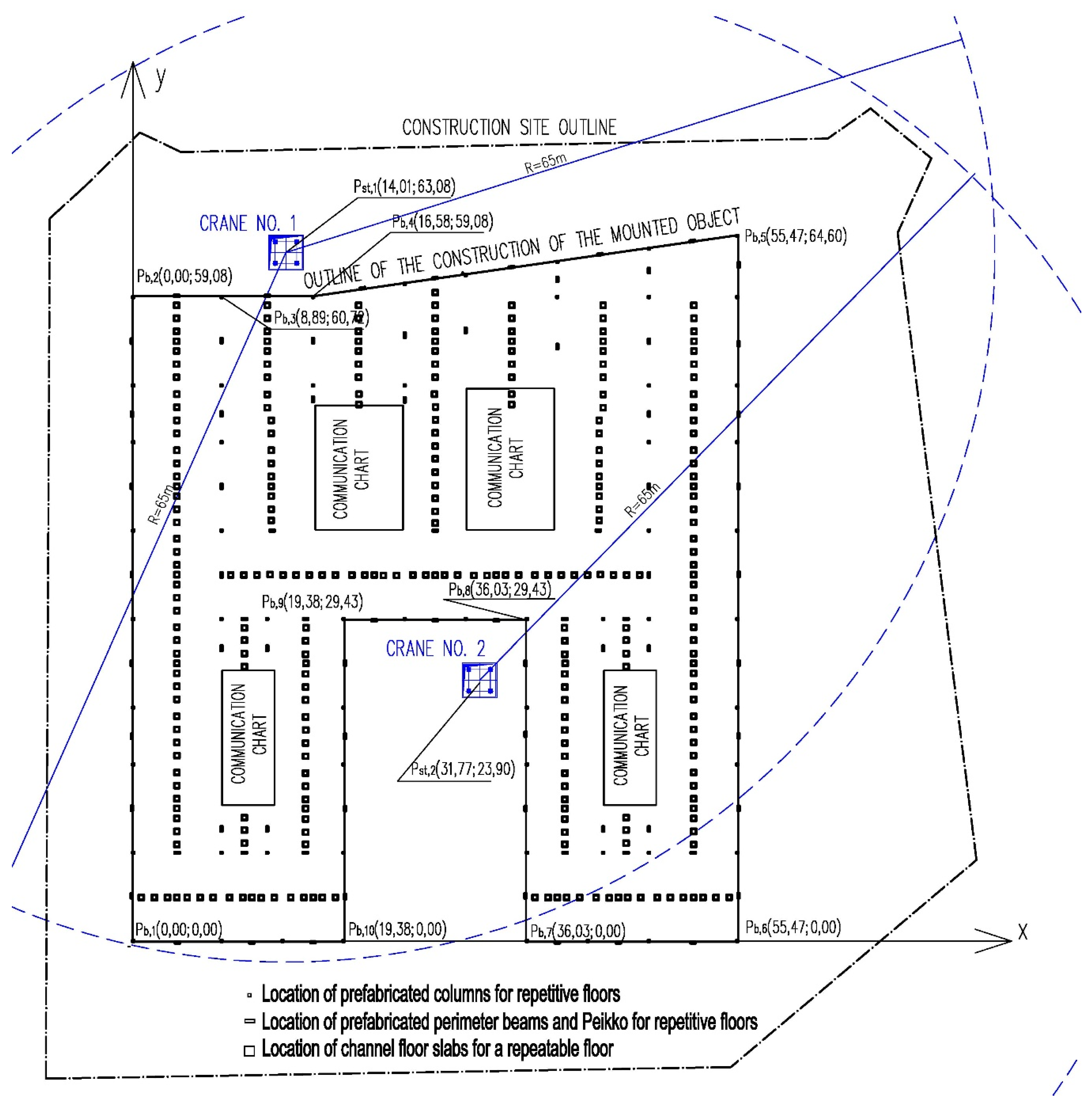
The construction was assembled using two Potain high-speed tower cranes with a load capacity of 10 tons. The third crane (crane No. 3 in Figure 5) was reserved for unloading materials other than prefabricated elements. The scheme of the construction site layout is shown in Figure 5. Due to the small area available, the assembly was planned as “just in time”. The fast pace of work required work in two shifts. On the second shift, prefabricated elements were mounted. The available number of cranes and large dimensions of the building allowed for a simultaneous work of two assembly brigades. The assembly works lasted over 3.5 months.
The assembly planning simulations, with the developed application, were carried out in six organizational variants.
The first variant reflects the actual schedule and it was done in order to check the correctness of the application. The origin of the coordinate system, the coordinates of the building’s corners and the location of cranes No. 1 and No. 2 were defined. Prefabricated elements, along with their characteristics, were also introduced (elements’ dimensions, weights and coordinates of their location in construction were obtained from the detailed design of the building). Slings’ weights and heights were determined by the planner. Durations of their assembly were calculated based on previous research on work processes. The chronological order of assembly was developed based on the actual schedule of works. The organizational layout of the assembly is shown in Figure 5.
Two high-speed Liebherr 202 EC-B 16 Litronic tower cranes with a maximum load capacity of 10 tons, similar to the Potain cranes, were used in the simulation. Logistic costs related to the site preparation, cranes’ transportation on site, assembly and dismantling were estimated at 10,000 PLN. The unit labor costs of one brigade include crane operation, mobile scaffolding and a 6-person assembly brigade. The unit costs of the brigade’s work were estimated at PLN 360.00 per hour. Separate costs of crane delivery and transportation characteristics were omitted. These costs were included, along with the assembly and disassembly of the cranes.
The works commencement date was set on 18 June 2016. Work began at 3.00 p.m. and ended at 11.00 p.m. The lifting height was increased by safety margin of 1.0 m. The number of simulations was set at 10.
For each of 10 simulations, its results are the same (excluding the variants in which only one crane is used). This is due to the lack of random factors. The simulation algorithm analyses two locations of cranes and two cranes of equal parameters. For such conditions, the completion date was calculated for 13 October 2016, which is similar to the actual schedule of works (10 October 2016) and indicates that the algorithm works correctly. The calculated assembly time is longer by three days in relation to the actual time spent on works due to overtime work. The cost of the assembly operations, according to calculations, is 552,576.80 PLN.
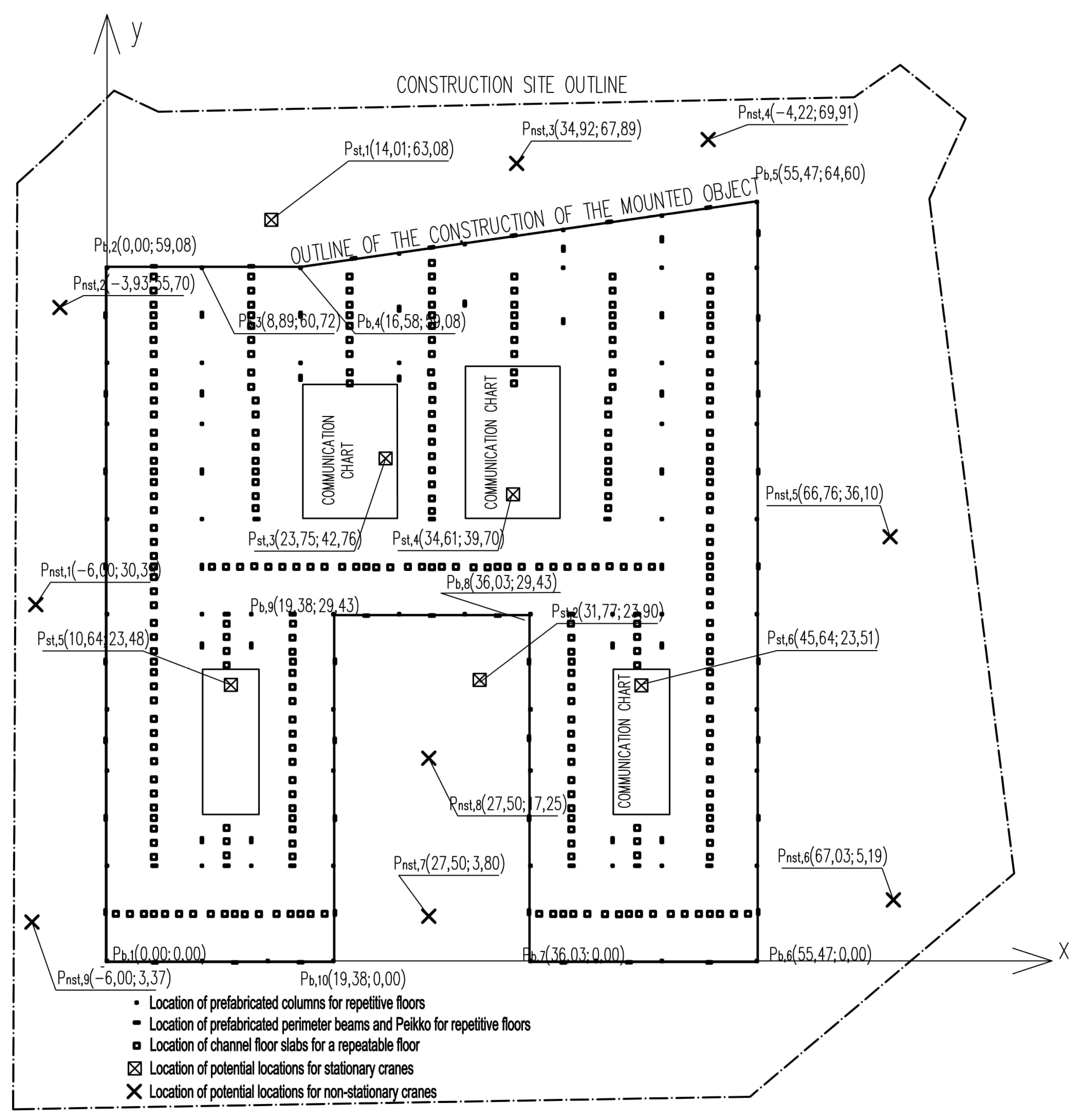
In order to obtain other assembly schedule variants, the initial assumptions were modified: additional possible locations for stationary cranes (in elevator shafts) and mobile cranes (on the site) were defined in accordance with Figure 6. The size of cranes’ pool was increased by two Liebherr 150 EC-B 8 litronic high-speed cranes, two Liebherr 172 EC-B 8 litronic cranes and three mobile cranes with a maximum load capacity of 50, 70, and 100 tons. In addition, the priority of stationary machines was set and the number of simulation increased to 100. The costs due to cranes utilization are collected in Table 2. The results of simulations are gathered in Table 3.
The perimeter beams played a key role in assembly works planning. It was necessary to mount them using large load capacity and large reach cranes. Stationary cranes’ size reduction (solution No. 2), mounting them in elevator shafts and using a mobile crane with a maximum load capacity of 70 tons allowed for the saving of approx. 19,000 PLN and 17 days of work. As the priority for stationary machines was set, most of the construction elements were mounted by these cranes. Mobile cranes were only used in the case of heavy perimeter beams.
Solution No. 3 was equally beneficial. In this solution, stationary cranes were located just like on the construction site. For this reason, they were able to assemble a smaller number of elements and a couple of tasks more was left for mobile cranes. The solution was slightly less cost-profitable, while the savings were c.a. 17,000 PLN, but assembly time shortened by 19 days compared to solution No 1.
Another favorable option was solution No. 4, in which two stationary cranes with a different maximum load capacity and a mobile crane was used. Cost savings were 18,000 PLN, but time-savings reached 20 days, in comparison to solution No 1.
The described case studies above prove that the cooperation between stationary and mobile cranes bring savings and improves assembly productivity. Using only tower cranes, without mobile crane support, as was the case in solution No 5, made the heaviest perimeter beams unmounted. Moreover, it increased assembly costs significantly, like in solution No. 6.
Sometimes it is a good idea to increase the number of stationary cranes, like in solutions No 7, No. 8 and No. 9. The optimal number of assembly machines was 3 (solution No. 7). Thanks to the simultaneous operation of all machines, the savings reached c.a. 31,000 PLN and the assembly time shortened by 29 days, in comparison to solution No. 1. However, such a solution might be dangerous, as overlapping operation areas of these cranes would cause numerous collisions and downtimes. Using more stationary cranes obviously shortened assembly duration, but did not bring financial benefits (see solutions No. 8 and No. 9).
The example shows that stationary cranes should constitute the main equipment for the assembly works. It is strictly related to the construction itself—its shape, area, number of floors or the number of elements to be mounted. In practice, as each assembly case is different, computer simulations can efficiently aid assembly planning.
When can mobile cranes be more profitable that the stationery ones?
If the Green2Day building consisted of only three floors, then the high costs of tower cranes mounting would not be balanced by lower unit costs of their work. Thanks to the lower height of the building, the required load capacity of mobile cranes could be smaller, which would lower unit assembly costs. This condition is particularly important for small space construction sites where cranes must be located close to the external walls of the building. If we considered a three-story building, the assembly costs for two mobile cranes with a maximum load capacity of 50 tons would be reduced by c.a. 14,000 PLN, in comparison to solution No. 1 (solution applied in practice, see Table 4).
The conclusions that can be drawn from the above examples are only binding for the analyzed object. In practice, construction projects differ in the number of elements to be assembled, their dimensions, weights, locations, as well as the availability of the construction site, machines and assembly brigades. Therefore, each project requires individual planning, which can be supported by the proposed computer application. Selecting the type of cranes’ construction, defining their potential locations, and setting the priority of stationary cranes allow for ongoing interaction between planner and computer, and hence, searching for a sub-optimal solution. The use of the presented simulative approach to assembly planning is not limited to planning prior to works commencement. If the pace of assembly works needs to be increased, it is possible to reorganize works at each stage of assembly, only taking into account yet unmounted elements.
3. Discussion and Conclusions
In the proposed method of assembly works planning, an active and key role is played by the planner who, based on their experience, and the results of historical simulations, has the ability to change the input assumptions. The size, first in regards to the load capacity of cranes, is effectively assessed by the number of unmounted elements in the solutions of subsequent simulations. If the number is large, it is a signal to the planner to change the size of the cranes. The potential locations of cranes can be effectively determined by the planner, assuming that he has elementary knowledge about the relationships between load capacity, reach and lifting height. The planner also does the final crane selection and assembly schedule, however, the developed method supports the decision-maker by presenting many acceptable solutions.
It should also be mentioned that the aim of planning is not always to choose the best solution for a selected construction project, but to achieve the smallest possible cost of works through the prism of the production potential. Therefore, it is not their goal to carry out works quickly on one particular construction site, but to use the production potential, construction equipment and workers effectively. The method of assembly planning cannot therefore focus on choosing one optimal solution that presents the most favorable ratio of the pace of works to their cost. The planner’s support consists of indicating available solutions, and assessing their quality. The final decision should always be left to the decision maker.
The method does not explicitly include collisions between cranes. Algorithmically, this problem is difficult to solve, because construction situations are unstable-they depend on many random factors. Therefore, other solutions are advised, e.g., planning cranes’ locations at a safe distance from each other or using anti crane collision systems and limit switches. This should solve the problem of work safety and collision-free assembly. As the spans of prefabricated elements are large, the work zones of cranes may overlap, but it does not affect the pace of work significantly if the planner or crane operator locates the machine skillfully.
Such an approach to the assembly planning problem was made in this paper—the planner indicates the potential locations of cranes in a way that reduces the risk of collision, while the possible risk of collision is eliminated using the already available techniques.
There are still several open issues in the problem of assembly planning that should be considered in the course of further research. These include, but are not limited to, the following:
- In the current formula, the planning tool prioritizes the order of assembly in accordance with the order proposed by the planner (order according to the list of elements to be mounted). Each assembled element is the predecessor of the next element to be assembled. In fact, this relationship primarily stems from the technological conditions and lets the planer decide freely about the order of assembly. The order of the elements to be mounted should be enriched by a matrix of dependency relations between the assembled elements and their predecessors, while decisions to move a mobile crane should be made after checking the possibility of assembling all elements for which the required predecessors have already been mounted. Such a solution would increase the effectiveness of the proposed method by reducing the number of necessary adjustments of mobile cranes.
- Introducing the characteristics of the mounted elements is tedious and time consuming. The proposed planning tool should be integrated with the BIM-based models in order to create the list of elements to be assembled and their characteristics automatically. The environment can also be used to import technological dependencies of assembly priority between individual elements, in accordance with point 1 above.
- The practical use of the proposed planning tool should be preceded by a comprehensive research on labor rates for prefabricated elements assembly. This should be the basis for the division of construction elements by the assembly duration (expected average value and standard deviation). The results obtained with the abovementioned research should be the basis for extending the proposed planning tool in order to include analyses in probabilistic conditions. The wide-range implementation of the research may be possible thanks to the constant reading of operating parameters and assigning mounting hook locations to the mounted elements. In the light of the emerging 5G technology and developing Internet of Things technology, the proposed method can constantly evolve.
- The proposed planning tool could be commonly used if the above mentioned problems are investigated. The graphical interface of the described application needs to be improved so it could be commercialized. The above presented possibilities of improving the computer application prove its potential and complexity of the problem as a whole.
The authors intend to use the proposed planning tool to plan assembly works in real planning situations. The practical application of the planning tool will be the subject of future publications
Author Contributions
Conceptualization, R.M. and M.B.; methodology, R.M. and M.B.; software, M.B.; validation, R.M. and M.B.; formal analysis, R.M.; resources, M.B.; writing—original draft preparation, M.B.; writing—review and editing, R.M.; supervision, R.M.; project administration, R.M.; funding acquisition, R.M. and M.B. All authors have read and agreed to the published version of the manuscript.
Funding
This research received no external funding.
Conflicts of Interest
The authors declare no conflict of interest.
References
- Gray, C.; James Little, J. A Systematic Approach to the selection of an appropriate crane for a construction site. Constr. Manag. Econ. 1987, 3, 121–144. [Google Scholar] [CrossRef]
- Gray, C. Crane location and selection by computer. In Proceedings of the 4th Int. Symp. Robotics and Artificial Intelligence in Building Construction, Haifa, Israel, 22–25 June 1987; Volume 1, pp. 163–167. [Google Scholar]
- Furusaka, S.; Gray, C. Model for the selection of the optimum crane for construction sites. Constr. Manag. Econ. 1984, 2, 157–176. [Google Scholar] [CrossRef]
- Warszawski, A.; Peled, N. An expert system for crane selection and location. In Proceedings of the 4th Int. Symp. Robotics and Artificial Intelligence in Building Construction, Haifa, Israel, 22–25 June 1987; Volume 1, pp. 64–75. [Google Scholar]
- Warszawski, A. Expert system for crane selection. Constr. Manag. Econ. 1990, 82, 179–190. [Google Scholar] [CrossRef]
- Cooper, C.N. Cranes—A rule-based assistant with graphics for construction planning engineers. In The Application of Artificial Intelligence Techniques to Civil and Structural Engineering; Civil Comp Press: Edinburgh, UK, 1987; pp. 47–54. [Google Scholar]
- Farrell, C.W.; Hover, K.C. Computerized crane selection and placement for the construction site. In Proceedings of the 4th Int. Conf. on Civiland Structural Engineering Computing; Topping, B.H.V., Ed.; Civil Comp Press: Edinburgh, UK, 1989; Volume 1, pp. 91–94. [Google Scholar]
- Choi, C.W.; Harris, F.C. A model for determining optimum crane position. ICE Proc. 1991, 90, 627–634. [Google Scholar]
- Zhang, P.; Harris, F.C.; Olomolaiye, P.O.; Holt, G.D. Location optimization for a group of tower cranes. J. Constr. Eng. Manage. 1999, 125, 115–122. [Google Scholar] [CrossRef]
- Williams, M.; Bennett, C. ALPS: The Automated Lift Planning System. In Proceedings of the ASCE Third Congress on Computing in Civil Engineering, Anaheim, CA, USA, 17–19 June 1996. [Google Scholar]
- Ito, K.; Kano, Y. 3-D Graphical Simulation for Crane Planning using Object-Oriented Building Product Model. In Proceedings of the CIB proceedings Information Technology Support for Construction Process Re-engineering, Cairns, QLD, Australia, 9–11 July 1997. [Google Scholar]
- Meehan, J. Computerize to organize. Cranes Today 2005, 369, 50. [Google Scholar]
- North Cascade Industrial (NCI). Compu-Crane CSPS/LPS: Crane Selection and Lift Planning Software, Seattle. Available online: www.ncisoftware.com (accessed on 7 July 2018).
- Cranimax. Cranimation and TowerManagement: Software for Crane Job Site Planning; Cranimax GmbH: Zweibrücken, Germany; Available online: www.cranimation.org (accessed on 7 July 2018).
- LiftPlanner Software. LiftPlanner: 3D Crane and Rigging Lift Planning Software, Burnsville, MN, USA. Available online: www.liftplanner.net (accessed on 10 August 2018).
- Progistik. MéthoCAD, Progistik, Bagnolet, France. Available online: www.methocad.com (accessed on 12 July 2018).
- Hanna, A.S.; Lotfallah, W.B. A fuzzy logic approach to the selection of cranes. Autom. Constr. 1999, 8, 597–608. [Google Scholar] [CrossRef]
- Sawhney, A.; Mund, A. Adaptive probabilistic neural network-based crane type selection system. J. Constr. Eng. Manage. 2002, 128, 265–273. [Google Scholar] [CrossRef]
- Tam, C.M.; Tong, T.K.L.; Chan, W.K.W. Genetic algorithm for optimizing supply locations around tower crane. J. Constr. Eng. Manage. 2001, 127, 315–321. [Google Scholar] [CrossRef]
- Shapira, A.; ASCE, F.; Goldenberg, M. “Soft” Considerations in Equipment Selection for Building Construction Projects. J. Constr. Eng. Manag. Asce 2007, 133, 749–760. [Google Scholar] [CrossRef]
- Dalalah, D.; AL-Oqla, F.; Hayajneh, M. Application of the Analytic Hierarchy Process (AHP) in Multi-Criteria Analysis of the Selection of Cranes. Jordan J. Mech. Ind. Eng. 2010, 4, 567–578. [Google Scholar]
- Günthner, A.; Kessler, S.; Tölle, S. BKT Turmdrehkran-Einzatzplaner; Leaflet Munich University of Technology: Munich, Germany, 1998. [Google Scholar]
- Günthner, A.; Kessler, S.; Tölle, S. Entwicklung eines Turmdrehkran-Einsatzplaners; Research report; Technische Universität München: Munich, Germany, 2002. [Google Scholar]
- Günthner, A.; Kessler, S.; Frenz, T.; Hefele, R.; Walter, M. Digital Tower Crane Deployment Planner, BauPortal 6-7. Available online: www.baumaschine.de/Krane (accessed on 10 August 2018).
- Tork, A.Z. A real-time crane service scheduling decision suport system (CSS-DSS) for construction tower cranes. Ph.D. Thesis, Department of Civil, Environmental and Construction Engineering in the College of Engineering and Computer Science at the University of Central Florida, Orlando, FL, USA, 2013. [Google Scholar]
- Lei, Z.; Behzadipour, S.; Al-Hussein, M.; Hermann, U. Application of robotic obstacle avoidance in crane lift path planning. In Proceedings of the 28th International Symposium on Automation and Robotics in Construction, ISARC, Seoul, Korea, 29 June–2 July 2011. [Google Scholar]
- Han, S.H.; Al-Hussein, M.; Hasan, S.; Gökçe, K.U. Simulation of mobile crane operations in 3d space. In Proceedings of the 2012 Winter Simulation Conference, Berlin, Germany, 9–12 December 2012. [Google Scholar]
- Han, S.H.; Hasan, S.; Lei, Z.; Sadiq Altaf, M.; Al-Hussain, M. A framework for crane selection in large-scale industrial construction projects. In Proceedings of the 30th International Symposium on Automation and Robotics in Construction and Mining (ISARC), Montreal, QC, Canada, 11–15 August 2013. [Google Scholar]
- Lei, Z.; Taghaddos, H.; Hermann, U.; Al-Hussein, M. A methodology for mobile crane lift path checking in heavy industrial projects. Autom. Constr. 2013, 31, 41–53. [Google Scholar] [CrossRef]
- Han, S.H. BIM-based Motion Planning of Mobile Crane Operation in Modular-based Heavy Construction Sites. Ph.D. Thesis, Department of Civil and Environmental Engineering University of Alberta, Edmonton, AB, Canada, 2014. [Google Scholar]
- Krawczyńska-Piechna, A. Comprehensive Approach to Efficient Planning of Formwork Utilization on the Construction Site. Procedia Eng. 2017, 182, 366–372. [Google Scholar] [CrossRef]
- Banach, M. Model wyboru wielkości urządzenia dźwigowego do wykonania robót montażowych. In Aktualne Problemy Naukowo-Techniczne Budownictwa, 1st ed.; Krawczyńska-Piechna, A., Ed.; Warsaw University of Technology: Warsaw, Poland, 2016; pp. 75–83. [Google Scholar]
- Banach, M. Interaktywna Metoda Planowania Robót Montażowych w Budownictwie Prefabrykowanym. Ph.D. Thesis, Warsaw University of Technology, Warsaw, Poland, 2019. [Google Scholar]
Figure 1.
A block diagram of the assembly planning system. Sourced from our own study.

Figure 2.
“Green2Day” office building front view. Investor: Tenali Investments Ltd. and Trikala SCA. Designers: Maćków Pracownia Projektowa LP & Grupa Projektowa Konstruktor Ltd. Own study.
Figure 2.
“Green2Day” office building front view. Investor: Tenali Investments Ltd. and Trikala SCA. Designers: Maćków Pracownia Projektowa LP & Grupa Projektowa Konstruktor Ltd. Own study.

Figure 3.
The Green2Day building slabs’ layout—Part 1. The design drawing was obtained from Grupa Projektowa Konstruktor Ltd.
Figure 3.
The Green2Day building slabs’ layout—Part 1. The design drawing was obtained from Grupa Projektowa Konstruktor Ltd.

Figure 4.
The Green2Day building slabs’ layout—Part 2. The design drawing was obtained from Grupa Projektowa Konstruktor Ltd.
Figure 4.
The Green2Day building slabs’ layout—Part 2. The design drawing was obtained from Grupa Projektowa Konstruktor Ltd.

Figure 5.
The organizational layout of assembly works the actual way of carrying out assembly works at the “Green2Day” facility.
Figure 5.
The organizational layout of assembly works the actual way of carrying out assembly works at the “Green2Day” facility.

Figure 6.
The organizational layout of assembly works-the potential locations of cranes for the assembly of the “Green2Day” facility.
Figure 6.
The organizational layout of assembly works-the potential locations of cranes for the assembly of the “Green2Day” facility.


Table 1.
List of reinforced concrete prefabricated elements to be mounted in the “Green2Day” building. Our own study based on the design by Grupa Projektowa Konstruktor Ltd.
Table 1.
List of reinforced concrete prefabricated elements to be mounted in the “Green2Day” building. Our own study based on the design by Grupa Projektowa Konstruktor Ltd.
| Type of Item | Total Number of Items |
|---|---|
| Column 50 × 70 cm | 98 |
| Column 50 × 50 cm | 287 |
| Column 60 × 60 cm | 28 |
| Peripheal beam (length 5.0–6.0 m) | 182 |
| Peripheal beam (length 8.0–8.5 m) | 112 |
| Peripheal beam (length 1.8–4.0 m) | 84 |
| DELTABEAM (length 4.0–6.0 m) | 49 |
| DELTABEAM (length 6.0–8.0 m) | 91 |
| DELTABEAM (length 8.0–10.0 m) | 35 |
| Floor slab HC width 50 cm, length 3.5–6.0 m | 14 |
| Floor slab HC width 120 cm, length 3.5–6.0 m | 217 |
| Floor slab HC width 50 cm, length 6.0–9.0 m | 182 |
| Floor slab HC width 120 cm, length 6.0–9.0 m | 1512 |
| Element of stairs | 42 |
| Total: | 2933 |
Table 2.
Cost characteristics of the assembly machines shown in the example. Sourced from our own study.
Table 2.
Cost characteristics of the assembly machines shown in the example. Sourced from our own study.
| Crane Delivery Cost, PLN/km * | Distance between Crane’s Base and the Construction Site, km | Crane Assembly and Disassembly Costs, PLN ** | Unit Operating Costs; Includes Crane’s Work and Assembly Brigade Work PLN/h | The Time Limit of Crane Underutilization, h *** | |
|---|---|---|---|---|---|
| Top-slewing tower cranes | |||||
| Liebherr 150 EC-B 8 litronic | 0.00 | 0 | 9,000.00 | 320.00 | 0 |
| Liebherr 170 EC-B 8 litronic | 0.00 | 0 | 9,500.00 | 340.00 | 0 |
| Liebherr 202 EC-B 16 litronic | 0.00 | 0 | 10,000.00 | 360.00 | 0 |
| Mobile cranes | |||||
| Liebherr LTM 1050-3.1 (50T) | 4.00 | 20 | 0.00 | 370.00 | 8 |
| Liebherr LTM 1070-4.2 (70T) | 6.00 | 20 | 0.00 | 400.00 | 8 |
| Liebherr LTM 1100-4.2 (100T) | 12.00 | 20 | 0.00 | 470.00 | 8 |
* crane delivery cost is included in the costs of assembly and disassembly. ** crane assembly and disassembly costs for mobile cranes are included in cost of assembly works; they are designated as the product of machine assembly and disassembly duration, the number of necessary crane relocations within the site and unit operating costs that include the work of the assembly brigade. *** the time when the assembly team cannot work; it happens if the crane has no lifting capacity for several subsequent elements, or the crane awaits for the assembly of the preceding elements mounted by other assembly team, or if the priority of stationary crane is set. This time influences on the loss cost due to the underutilization of assembly. This cost may be negligible if the time of underutilization allows the crane (and the assembly brigade) to carry out another construction project. In the example, it was assumed that, in the case of mobile cranes, the minimum negligible time of crane underutilization is 0 or 1 working day (8 h).
Table 3.
The results of t computer simulations-description in the text. Sourced from our own study.
| No. | Assembly Machines | Assembly Cost, PLN | Assembly Duration, in Days | Number of Unmounted Elements |
|---|---|---|---|---|
| 1 | 2 x Liebherr 202 EC-B 16 litronic | 552,576.80 | 98 | 0 |
| 2 | 2 x Liebherr 170 EC-B 8 litronic Liebherr LTM 1070-4.2 (70T) | 531,660.20 | 81 | 0 |
| 3 | 2 x Liebherr 170 EC-B 8 litronic Liebherr LTM 1070-4.2 (70T) | 533,851.10 | 79 | 0 |
| 4 | Liebherr 202 EC-B 16 litronic Liebherr 150 EC-B 16 litronic Liebherr LTM 1070-4.2 (70T) | 533,974.11 | 78 | 0 |
| 5 | Liebherr 202 EC-B 16 litronic Liebherr 150 EC-B 16 litronic | 528,989.20 | 86 | 103 |
| 6 | Liebherr 170 EC-B 8 litronic Liebherr LTM 1070-4.2 (70T) Liebherr LTM 1100-4.2 (100T) | 607,169.52 | 69 | 0 |
| 7 | Liebherr 202 EC-B 16 litronic 2 x Liebherr 150 EC-B 8 litronic | 520,929.42 | 69 | 17 |
| 8 | 2 x Liebherr 150 EC-B 8 litronic 2 x Liebherr 170 EC-B 8 litronic | 525,384.48 | 50 | 0 |
| 9 | 2 x Liebherr 150 EC-B 8 litronic 2 x Liebherr 170 EC-B 8 litronic Liebherr 202 EC-B 16 litronic | 544,071.68 | 41 | 0 |
Table 4.
Selected results of the computer aided assembly planning for the first 3 floors of the building-description in the text. Sourced from our own study.
Table 4.
Selected results of the computer aided assembly planning for the first 3 floors of the building-description in the text. Sourced from our own study.
| No. | Assembly Machines | Assembly Cost, PLN | Assembly Duration, in Days | Number of Unmounted Elements |
|---|---|---|---|---|
| 1 | 2 x Liebherr 202 EC-B 16 litronic | 248,247.20 | 42 | 0 |
| 2 | 2 x Liebherr 170 EC-B 8 litronic Liebherr LTM 1070-4.2 (50T) | 237,496.30 | 35 | 0 |
| 3 | 2x Liebherr LTM 1050-4.2 (50T) | 234,587.40 | 43 | 0 |
| 4 | 3x Liebherr LTM 1050-4.2 (50T) | 235,241.80 | 29 | 0 |
© 2020 by the authors. Licensee MDPI, Basel, Switzerland. This article is an open access article distributed under the terms and conditions of the Creative Commons Attribution (CC BY) license (http://creativecommons.org/licenses/by/4.0/).
Share and Cite
MDPI and ACS Style
Marcinkowski, R.; Banach, M. Computer Aided Assembly of Buildings. Buildings 2020, 10, 28. https://doi.org/10.3390/buildings10020028
AMA Style
Marcinkowski R, Banach M. Computer Aided Assembly of Buildings. Buildings. 2020; 10(2):28. https://doi.org/10.3390/buildings10020028
Chicago/Turabian StyleMarcinkowski, Roman, and Maciej Banach. 2020. "Computer Aided Assembly of Buildings" Buildings 10, no. 2: 28. https://doi.org/10.3390/buildings10020028
Note that from the first issue of 2016, this journal uses article numbers instead of page numbers. See further details here.