1. Introduction
In the design of high-rise buildings, tallness causes a great vulnerability of the structure to horizontal loads, which must be compensated for by providing adequate lateral performance in order to satisfy strength, stiffness and stability requirements. In particular, recent advances in improving the structural efficiency of tall buildings are directed toward a new generation of façade grids with geometric unit cell configurations: DiaGrid, PentaGrid, HexaGrid, OctaGrid, and the so-called Voronoi-grid. A comprehensive study of new trends in grid-like structures is presented in [
1], which provides an overview of conventional and unconventional patterns for twisted, tilted, tapered and freeform tall buildings. In recent developments, the tessellated structural system has evolved into other innovative schemes, the so-called nature-mimetic patterns, which represent a source of inspiration for a new generation of structural grids. Such biomimetic patterns are derived by the arrangement of regular and irregular unit cells, in order to create aesthetically attractive façades. The work presented by Mele et al. in [
2] explored bio-inspired patterns (HexaGrid and Voronoi tessellations) and proposed a generalized methodology to deal with the preliminary design of these geometrical layouts. In Angelucci and Mollaioli [
3], different case studies, accounting for various levels of irregularity and relative density of the Voronoi pattern, were generated and analyzed for both regions with high wind load conditions and areas of high seismicity.
Due to the high efficiency exhibited together with the limited use of structural material, diagrid systems have undeniably been the most recurrent tubular typology, among the aforementioned geometrical patterns, for high-rise buildings built in recent decades. The diagrid structure is a perimeter resisting system made up of narrow diagonal members capable of transferring both gravity and lateral loads, due to the high bending and shear stiffness provided. Since the early contribution of Moon et al. (2007) on the study of optimal diagonal inclination and the formulation of a preliminary stiffness-based design methodology, the investigation on diagrid systems has undergone remarkable developments in recent decades [
4]. Montuori et al. [
5] analyzed to what extent stiffness and strength criteria affect the design of diagrid structures, stating that, in general, both criteria are necessary and unavoidable. In Montuori et al. [
6] diagrid structures with regular patterns were compared to alternative geometrical configurations, obtained by changing the slope and the number of diagonals along the building height. Angelucci and Mollaioli [
7] compared models with different non-uniform patterns to evaluate the most effective configuration, achieving a condition of optimality when strength and stiffness demands meet. Different geometrical patterns for diagrid structures were also explored by Tomei et al. [
8] by performing an optimization process based on weight minimization using genetic algorithms. In the contribution of Lacidogna et al. [
9] the analysis of external diagrid systems coupled with closed-section and open-section shear walls was performed by recurring to the General Algorithm [
10] for the assessment of displacements and stresses [
11,
12].
Recent efforts in the design of tall buildings have been made by researchers toward the evaluation of optimal topologies, i.e., the lightest and best performing choices among a large set of design alternatives. The design of lateral bracing systems, for example, requires the selection of a suitable pattern for the diagonals arrangement, which is commonly performed through trial-and-error procedures. In this context, topology optimization represents an effective tool for improving the design of tall buildings and has been found to be useful for the definition of efficient and innovative structures. Examples of design applications on multi-story buildings are presented in Liang et al. [
13], Stromberg et al. [
14], Angelucci et al. [
15]. A modest number of works have also focused on lateral load resisting braced frames, designed by means of topology optimization techniques using 3D domains (Beghini et al. [
16], Angelucci et al. [
17]).
Inspired by the high mechanical performance of diagrid structures, the minimization of material consumption on braced frames and the expressive potency of tensegrity modular structures, this work proposes the application of tetrahedral structural systems in the design of tall buildings.
To date, several experimentations using the tensegrity philosophy have been addressed toward tower structures, e.g., the Needle Tower and Needle Tower II by Snelson, the Santiago Antenna Tower, the tower designed by Aurel von Richthofen in Dubai, the Tensegrity Barcelona Tower, the tensegrity tower in Tokyo designed by Otypka and the Warnow Tower in Rostock. Generally, in tensegrity towers, simplex modules based on three struts are stacked on top of each other [
18]. Recent studies by Skelton on tensegral towers are to be counted among the most valid examples of tensegral application in engineering [
19]. In the context of theoretical and experimental studies carried out by Froli and Laccone on the behavior of glass structures, a promising application of Solidi Vitrei Tensegrity (SVT) systems was proposed in 2018 with a 27-m-high SVT tower, the so-called Hyglass tower [
20,
21]. Lately, optimization schemes have also been applied to the design of tensegrity structures, either seeking to identify structural forms for a given set of element (i.e., bar and cable) connectivity or as a tool for determining optimal tensegrity configurations between nodes. Recent achievements are provided by Pandian and Ananthasuresh [
22], Xu et al. [
23], Liu and Paulino [
24], Nanayakkara et al. [
25].
The basic concept of tetrahedral system proposed in this paper; however, markedly differs from that of tensegrity, which is by definition a system in a stable self-equilibrated state comprising compression members (struts) and tensile members (tendons) in a specific topology stabilized by induced prestress [
19]. The paper proposal, on the other hand, consists of a reticular system based on tetrahedral modules and designed to resist both gravity and lateral loads. The assembly of triangular prisms (i.e., the so-called base modules) placed one next to the other, allows the generation of bigger, continuous, and compact triangular checkered units, which can be shaped into various configurations. This work deals with the investigation of the mechanical behavior of this new typology under the influence of external loading scenarios. Guidelines for the most cost-effective design, in terms of material usage, are defined along with evaluations of the most suitable module geometry to maximize the overall performance of the tall building. A stiffness-based methodology is proposed for determining preliminary member sizes based on serviceability requirements. The approach is finally applied to a set of structures with various unit module assemblies.
2. Genesis of the Structural Proposal
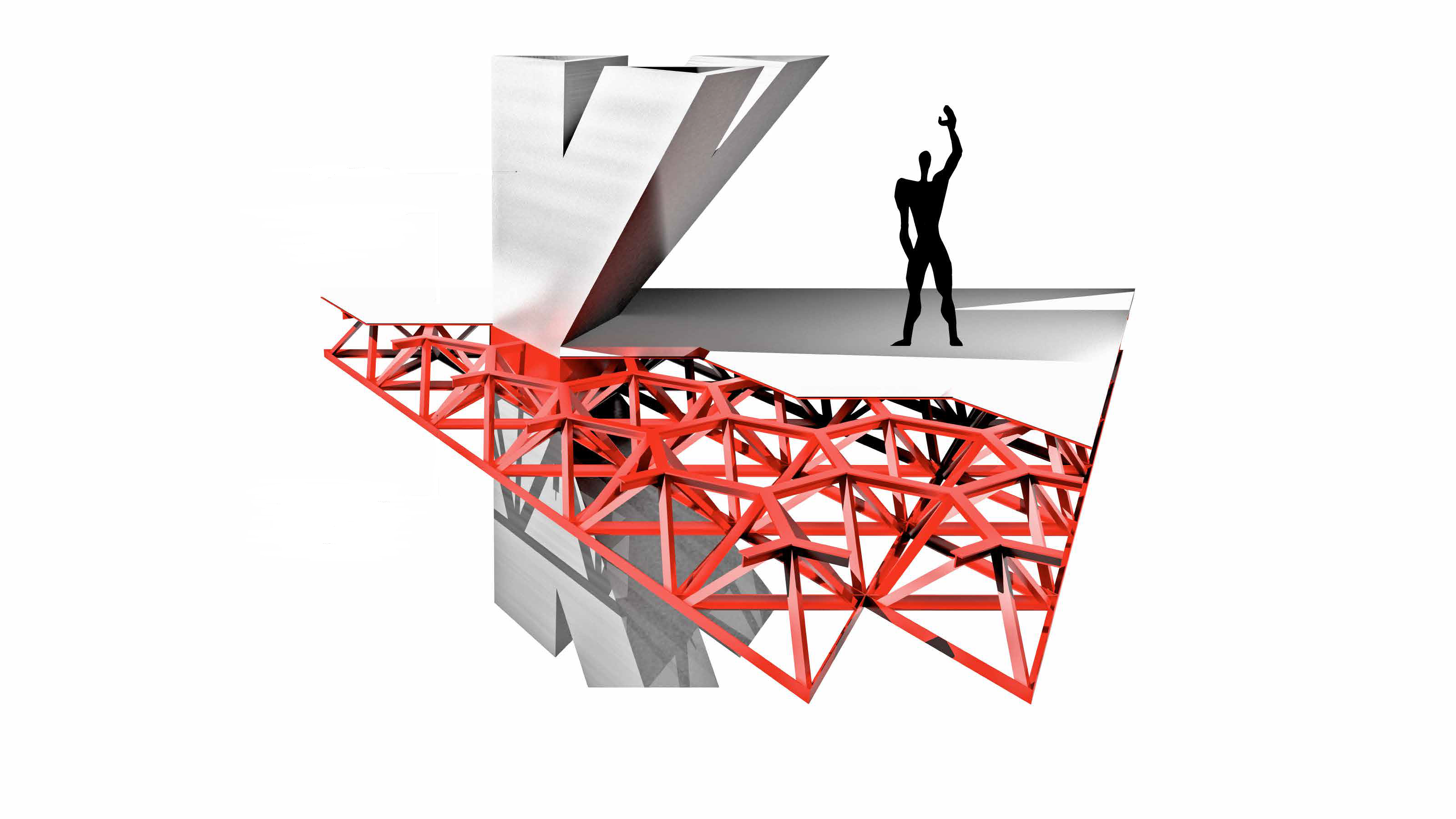
The design proposal arises from the evaluation of the most effective systems in resisting the horizontal forces acting on tall buildings, together with considerations on the modular units. The simplest two-dimensional system at the base of non-deformable structures is notoriously the triangular configuration, from which the diagrid system derives its high mechanical performance, in terms of stiffness and strength. The transposition into the three-dimensional space of the planar triangular pattern is properly the tetrahedral configuration. The modular tetrahedral structure has been widely adopted by engineers, architects, and artists due to its stability and construction simplicity in addition to its adaptability in tessellating the space. The proposal of a three-dimensional tetrahedral structure is the result of intuitive considerations, which develop through structural evaluations and evolve into a spatial language. It is, therefore, inevitable to emphasize the architectural and engineering implications of such design suggestion. The architectural vision is that of a high truss organized through prefabricated mega-modules that aesthetically incorporate the poetics of ‘the out-of-scale’ (
Figure 1).
As is well known, tall buildings are subjected to gravity forces due to permanent and accidental loads, transmitted to the resisting members from the floors, and lateral forces mainly due to wind pressure. In traditional structural systems, the commonly adopted strategy is to provide the tall building with a large, dimensionally invasive core, which fulfills the task of withstanding vertical and horizontal actions and transmitting them to the foundation. The objective of the proposed system, on the contrary, is to provide the modules with sufficient stiffness to avoid large displacements at the top of the building, without relying on inner cores. In fact, the main advantage of the modular tetrahedral structure, compared to other resisting systems for tall buildings, lies in the potential rigidity offered by the three-dimensionality of the diagonal members and their plasticity in shaping the architectural space. The large voids of the structural system allow the internal spaces of the tower to be distributed with greater compositional freedom, e.g., organization of suspended gardens, meeting places, collective services and more. The massive diagonal elements penetrate the architectural organism ensuring the flow of people and systems, without any restriction on the specific planimetric location. Vertical connections (elevators, goods lifts, emergency stairs) may follow organizational and compositional choices more closely, rather than structural limitations.
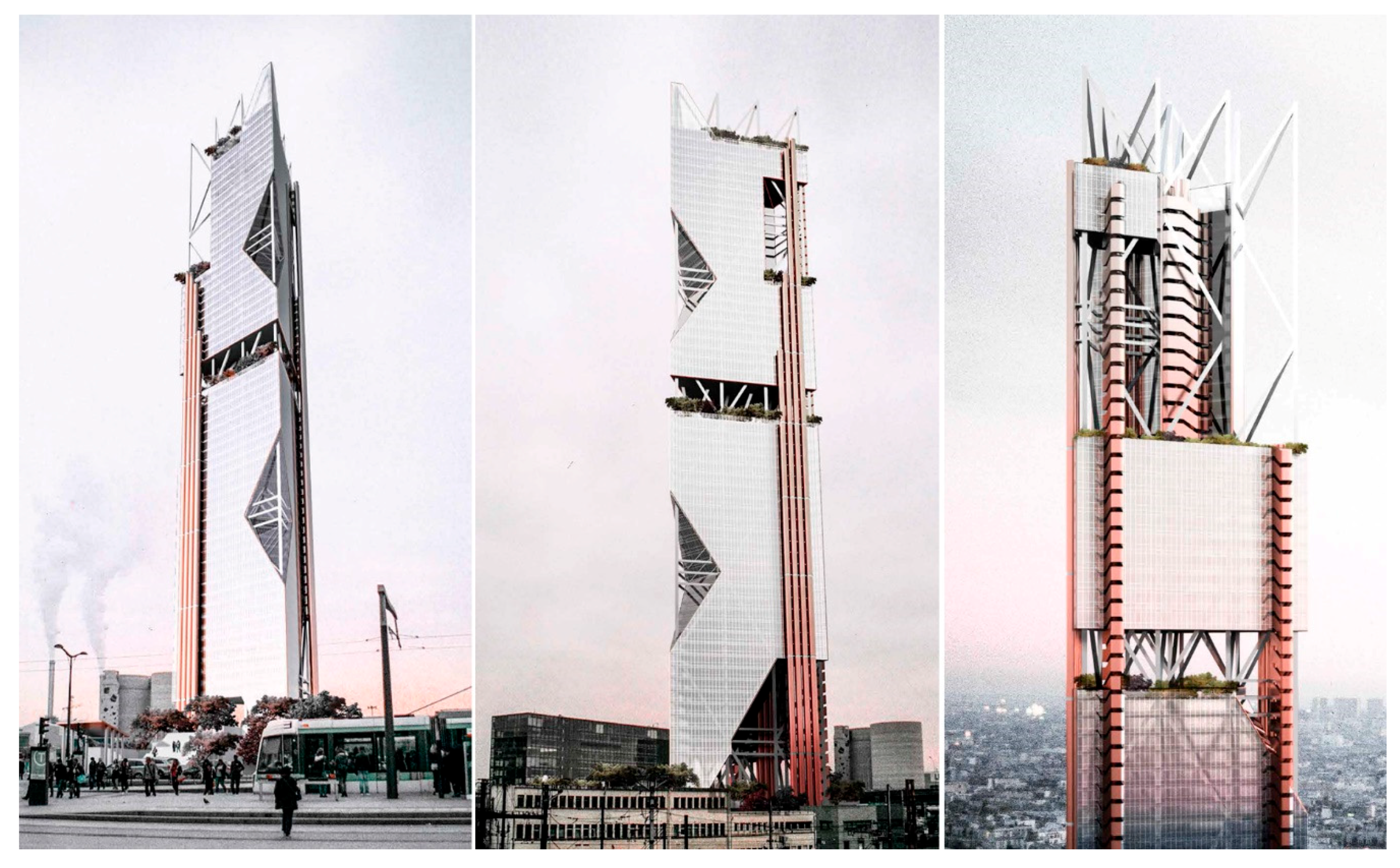
Figure 1,
Figure 2 and
Figure 3 illustrate a feasible application of the proposed structural system, based on the juxtaposition of unit tetrahedral modules. The design model depicted represents a visual example, among many possible typologies, with the aim of providing information on how the proposed system can be arranged in a tall building. Architectural solutions are also included in the figures to exemplify the distribution of interior spaces and exterior façades. The tall building is 259 m high with a triangular base of 47.25 m and a typical story height of 3.7 m. The complete structural system is composed of nine tetrahedral base modules combined in plan to form a triangular configuration. Ten modules are assembled along the elevation, each of which contains ten vertical members and fifteen diagonal members.
The macro-structure based on modular units is fully identified in all its design and constructive aspects once the base module is geometrically defined. In other words, the geometrical archetype is the planar triangle, specified by the designer, which shapes the plan of the tall building, the tetrahedral grid, the structural members, the floor slabs and the façades. This reduction of the global system to the elementary unit makes the whole building perfectly assemblable and modular. It is precisely in this coexistence and contradiction of global and local, complex and unitary, spatial and planar, and triangle and tetrahedron that the philosophy of the proposed structural system resides.
3. Module-Based Approach
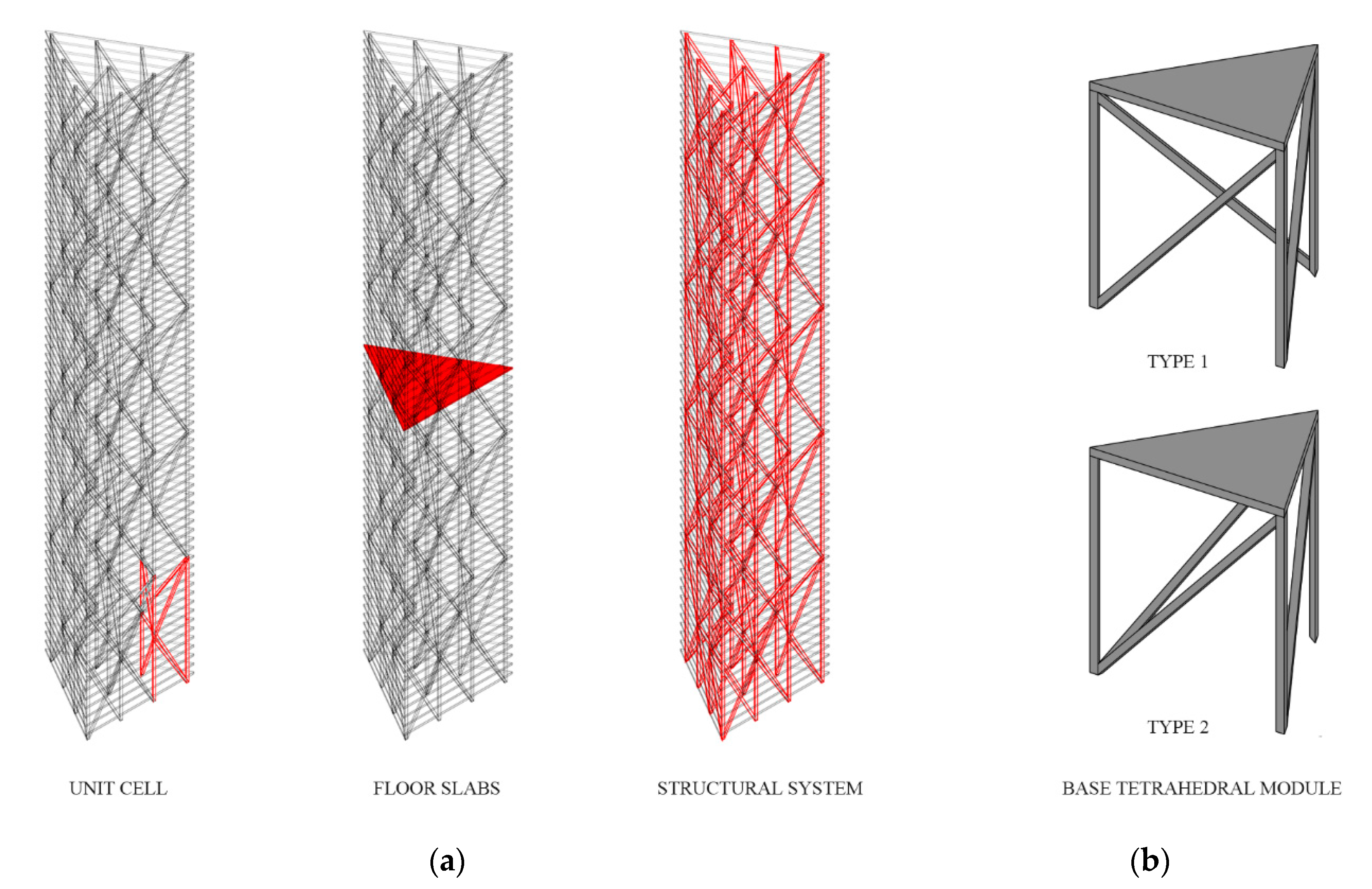
It is generally assumed that a tall building can be conceived as a vertical cantilever beam fixed at the base. By splitting up the structure lengthwise into modules, as shown in
Figure 4a, a repetitive pattern is obtained, with a single level of columns and diagonals extending over multiple stories. The subdivision of the building into modules is extremely useful as it allows evaluating the structural behavior of the overall lateral resisting system once the performance of the base module has been assessed. Furthermore, since the module extends over multiple floors, a constant cross-section is adopted for the structural members (columns and diagonals) included within the module height, i.e., the member size only varies from one module to another. This statement allows assuming that the design loads adopted for sizing each member are equivalent to those obtained at the base of the related module.
To apply the design methodology provided in the following sections of this paper, the tetrahedral pattern is preliminarily defined here. An initial examination is carried out to select an appropriate base module that fits the purpose of the present work. Based on the architectural, functional, and structural evaluations described in the previous section, the selection criteria are mainly based on compliance with three design requirements: triangular-based plan, not a twisted configuration, and reduced number of structural members. Among the topological classes of elementary cells for tensegrity structures, the untwisted version of the Three-struts prism (also called T-prism) is chosen. The T-prism belongs to a subclass of prismatoids and is the simplest arrangement of the tensegrity family. For the tensegrity structure to be stable and prestressed, the triangular faces of the regular prism are rotated relative to each other to attain an equilibrium configuration. Because, within the scope of this work, the twisting operation is not necessary to confer stability to the structure, the regular prism (Type 1) can be reasonably selected, as illustrated at the top of
Figure 4b. Following the same selection judgment and modifying the arrangement of the diagonal members, a second design of the base module is provided (as illustrated at the bottom of
Figure 4b). This Type 2 module is arranged to form three tetrahedral solids, dictated by symmetry and architectural considerations. The convergence of the diagonal rods at the base of the left column, in fact, is well suited to design the corners of the façades, allowing a symmetrical planning of solids and voids as shown in the rendering views of the previous figures.
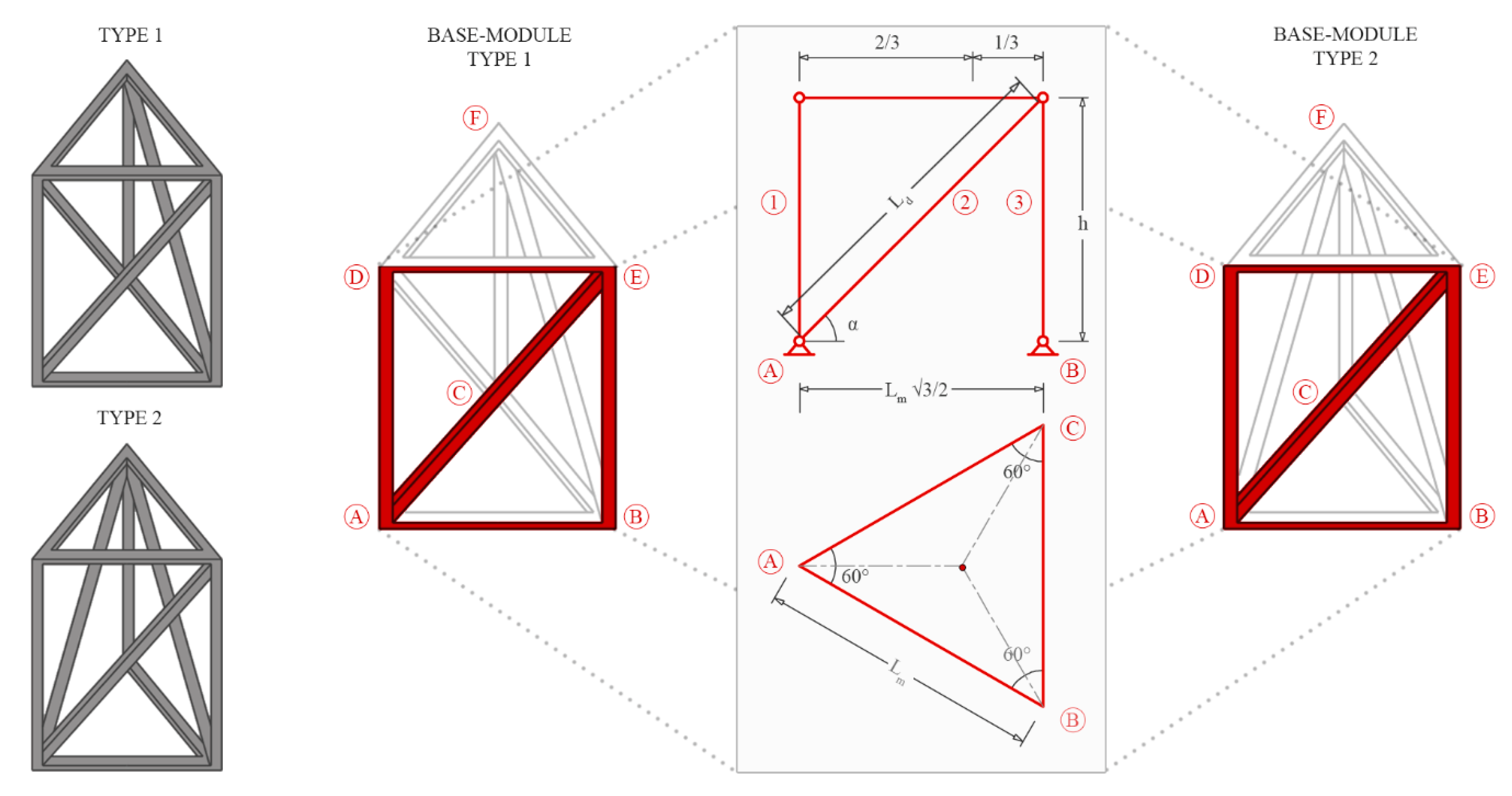
For both cases of defined configurations (Type 1 and Type 2), the base module is composed of nine structural members (i.e., three diagonals, three columns and three floor beams). The geometrical parameters constituting the module, which in turn influence its structural behavior, are the same, as illustrated in
Figure 5 and briefly described below. The module has an equilateral plan of width
. The module elevation (
) and the diagonal length (
) are both functions of the angle
comprised between the braces and the horizontal direction. The geometrical attributes of the unit cell and those of the global pattern are closely related since the parameters of the tetrahedral module apply to the global building dimensions. The building height
, the width
and the related aspect ratio (
) are uniquely defined by the number of modules along the elevation (
) and the number of modules assembled in plan (
). Once the plan is fixed, the parameters that govern the stress regime of the module are: the angle of inclination of the diagonals (which in turns determines the module height), the plan width and the point of application of the design load.
The constitutive modules ensure the global stiffness and strength demand of the overall building. The nodes, where diagonal and vertical members converge, as well as beam to column connections, are modeled as hinges. Therefore, the tetrahedral-like structural system resists both bending moments and shear forces, derived from lateral loads, through axial behavior. In the module, only tension and compression forces with extension and shortening deformations occur.
The mechanical response of either Type 1 or Type 2 modules is not affected by the specific application point of the barycentric force at nodes D, E, or F. This characteristic is extremely favorable for structures subjected to lateral load, given the aleatory nature of the wind direction. With reference to Type 2 module, the positioning of the diagonal BF or CE is also trifling. For the preliminary design study on the base module described below, the Type 2 system is elected on the basis of a comparative analysis. Diagonal members, arranged in the Type 2 configuration, exhibit equal shear stiffness but slightly higher flexural rigidity, compared to the Type 1 module. An in-depth study on the distribution of stresses in the two models, subjected to distinct shear and bending actions, highlights the peculiar mechanical behavior of the Type 2 in completely decouple the two contributions: diagonal members withstand the shear force while columns resist the bending action. As will be detailed in the next section, this feature is essential for deriving the proposed stiffness-based methodology. In addition, the Type 2 pattern is perfectly symmetrical with respect to the barycentric axis passing through point D and the centroid of the triangular plan. These motivations, aimed at defining a simplified preliminary approach, establish the convenience of the Type 2 model, whose mechanical behavior is discussed below.
The unit cell thus defined is isostatic and symmetrical, characteristics that allow converting the spatial problem into a two-dimensional one. This simplification of the model is particularly advantageous as it reduces the number of variables involved in evaluating the performance of the structural system and establishing a preliminary design methodology. With reference to the base module, a clarification is needed here. The presence of a transverse diagonal member, connecting points B and F (or, likewise, points C and E) of
Figure 5, causes torsional effects of the plane and moves the results away from the theoretical behavior. Relative rotations of the nodes contained in the upper floor occur due to the action of the braced member, transversely located to the direction of the point load. However, since this effect is observed only in the case of single modules (i.e., a purely theoretical situation) and because the structural system of realistic tall buildings is inevitably constituted of several juxtaposed units, it is considered plausible to exclude the diagonal BF from a preliminary evaluation of the base module. In fact, as the number of modules increases, the transverse diagonals collaborate in neutralizing the plan torsional effects. The diagonal inactivity is obtained by mimicking the presence of adjacent modules to nullify the rotational component. This expedient implies that the transverse diagonal is completely unloaded and its contribution can be neglected, without interfering with the global behavior of the base module. For this reason, the schematics provided to support the formulation of the preliminary design methodology for the base module lack the representation of a third diagonal. Furthermore, it can be demonstrated that in the absence of the transverse diagonal or when its contribution can be reasonably omitted, Type 1 and Type 2 modules show similar global stiffness. Therefore, under the assumption of two diagonal modules, the preliminary design equations, as formulated in the next section for Type 2, may also be considered valid for the Type 1 module.
4. Methodology for the Preliminary Design
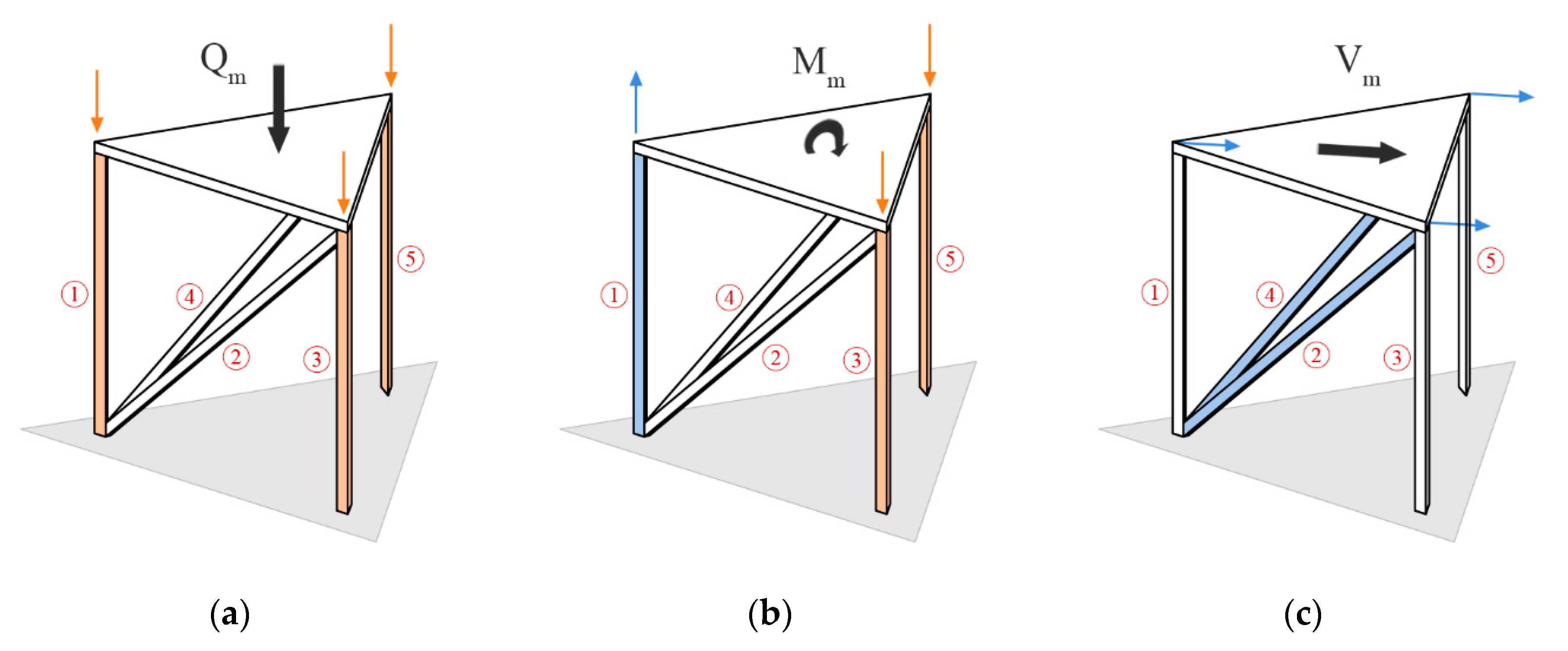
In this section, an approach for the preliminary design of tetrahedral-like systems for tall buildings is introduced. Based on the paths of vertical and lateral forces and considering the predominant resisting mechanism in the structural system, the procedure suggests a simplified formulation to derive optimal cross-sections for diagonal and column members. The generalized approach is finally extended to include the assembly of multiple modules. The preliminary design needs to be a quick and simple tool, thus leading to several assumptions in the model and the loading distribution, in order not to add further complexity to the overall problem. Support conditions are assumed to be fixed. Floor slabs are modeled to have infinite in-plane stiffness, constraining the nodes of each floor to have the same horizontal deflection. Hinged nodes allow columns and diagonals to resist overturning moments and shear forces through axial action only. A homogeneous and isotropic material with linear elastic behavior is assumed for the structural members, which enables exploiting the superimposition of the effects produced by the design loads acting on the structural model. Gravity and lateral loads are assumed to be applied at the center of the module plan and oriented along a centroid axis, as illustrated in
Figure 6.
A preliminary design methodology is defined, starting from the single module, through the following steps: (i) estimation of the stress distribution in the resistant members; (ii) application of the principle of virtual works (PVW) to evaluate the displacement due to the acting loads; (iii) assessment of the exhibited stiffness and required cross-sections. Referring to
Figure 6, the gravity load (
), the shear force (
) and the overturning moment (
) for the generic module are calculated as follows:
where
corresponds to the top level of the building and
is the base level of the
-th module;
is the
-th floor gravity load (unit gravity load multiplied by the total floor area),
is the shear force due to wind loads at the
-th floor and
is the vertical distance between the top of the building and the
-th level.
4.1. Lateral Loads
By making the classical assumption that the building structure under lateral loads behaves as an ideal cantilevered beam, uniform tensile and compressive forces arise in the leeward and windward faces, respectively, as a consequence of the overturning moment, while the faces parallel to the wind direction are subjected to shear forces. The lateral stiffness of the structure, which counteracts these global actions, is given by the sum of two components, i.e., flexural and shear. This statically determinate problem position corresponds to a state of uniform deformation [
7].
In tall buildings, it is reasonable to assume that stiffness, rather than strength, governs the structural design since serviceability requirements are dominant. Therefore, the preliminary design methodology presented hereafter is based on the stiffness demand, by specifying the contributions of bending and shear components to the total lateral deflection of the structure. This decomposition of the overall problem makes the investigation of the intrinsic attributes of the structural system more controllable and practical. The equations suggested for the preliminary design are expressed in terms of demand for bending and shear strain and are based on evaluations of the minimum amount of material employed among the many feasible design alternatives that meet stiffness requirements. The methodology is parametrically applied to tetrahedral-like structures of various heights and aspect ratios.
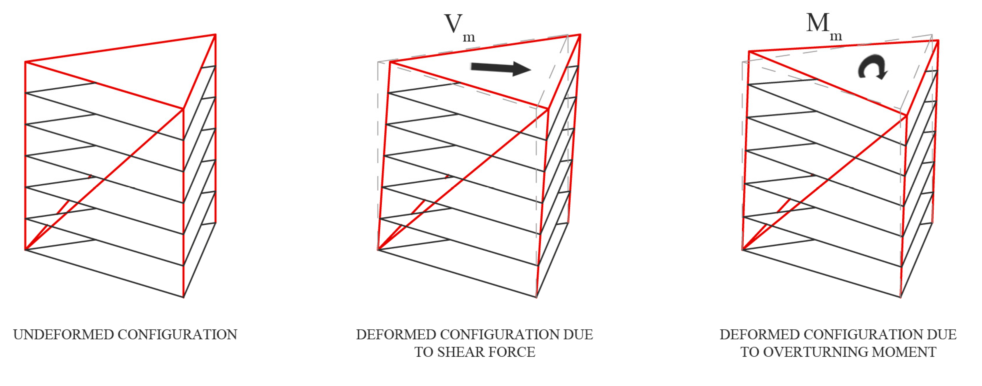
As illustrated in
Figure 7, the deflection at the top (
) can be written through the superimposition of the effects produced by shear (
) and bending (
) contributions, independently considered:
The diagonal members in the module carry the shear force only while the columns resist the overturning moment, both through axial action only (
Figure 6b,c). With this idealization, the preliminary design problem reduces to determining, for each module, the cross-section of vertical and inclined members, separately.
4.1.1. Displacement Due to Shear Forces
By adopting the PVW, the shear counterpart of the global deflection at the top is provided by the contribution of two diagonal members (
Figure 6c) through:
where
is the cross-section area of each diagonal,
is the elastic modulus of the design material,
is the diagonal length related to the module height
and the brace inclination
through
. The axial stress exhibited by each diagonal member of the real system (
) is:
where
is the shear force acting on the module calculated by means of Equation (1) and the building width
is equal to
in the case of a single module. The axial stress due to the virtual displacement is given by
. Substituting in Equation (3), the following displacement due to shear is obtained:
with the transverse shear stiffness given by
.
4.1.2. Displacement Due to Overturning Moment
A similar approach is adopted for estimating the bending contribution to the overall deflection of the building. The overturning moment due to the wind action gives rise to downward and upward forces on the module with uniform compressive and tensile stresses on the columns, respectively. It follows that:
where
is the cross-section area of each column and the subscripts 1 and 3 refer to the column numbering in
Figure 6. Because of symmetry, the contribution of column 3 is considered twice to also take account of column 5. The axial stress exhibited by column 3 in the real system is given by:
where the quantity in the denominator represents the lever arm of the internal couple and
is the bending moment calculated through Equation (1). The axial stress exhibited in the virtual system is given by:
Therefore, the contribution of columns 3 and 5 to the bending deflection is given by:
where
is the module location along the building elevation and
represents the distance of the
-th module with respect to the top of the building.
The axial stress of column 1, in the real system, is given by the base reaction (which is twice the base reaction of column 3) minus the contribution of the two diagonals:
The axial stress of column 1 produced by the virtual displacement is strictly dependent on the number of modules assembled along the elevation of the building:
According to the previous equation, the axial stress of the diagonals is proportional to the height of the single base module, while the axial stress of the column is proportional to the position of the module along the elevation of the structure (
). In fact, when
and the module height (
coincide, i.e., in the case of a module located at the top of the building,
is null. As a consequence, the column does not contribute to the bending component of the global displacement (
). Conversely, when two or more modules are assembled along the elevation, the column contribution cannot be neglected and needs to be considered in Equation (6), which assumes the following form:
4.1.3. Stiffness-Based Approach
Substituting the quantities in Equation (2) with those achieved in Equations (5) and (12), the global deflection of each module is assessed:
where
and
are the maximum shear force and bending moment, respectively, calculated at the base of each module. For the sake of completeness and clarity, shear forces and bending moments can be trivially assessed through the one-dimensional cantilever beam analogy with the same height of the building and loaded with lateral point loads at the top of each module.
In tall buildings, drift problems related to lateral loads are a dominant issue, so controlling the global lateral displacement becomes fundamental. The limit value of the horizontal displacement at the top of the tall building (
) is a design parameter, usually expressed by codes as a percentage of the building height:
where
is an engineering parameter, which assumes typical values comprised between 400 and 550. Once the target value of the building top displacement is fixed, preliminary design equations for deriving the member size can be formulated. However, because both shear and bending deformations concur to the total deflection, an adimensional parameter
is introduced to rate their relative contributions. The displacement measures
and
can also be expressed in terms of deformation measures:
where
is the curvature and
is the transverse shear strain. According to the previous equation, the targeted lateral displacement assumes the following form:
where the superscripts of
and
stand for the design values of the deformation components required to limit the top sway within the prescribed threshold. Without any loss of effectiveness, the same procedure can be adopted to restrain the top sway of each module. Therefore, equating the relationship (5) to the shear component of Equation (16) and replacing the global height
with the module elevation
, the following expression is achieved for each module:
Upper section for the diagonal members of each module can be sized according to:
with
. Analogously, the relationship in (12) is equated to the bending component in Equation (16):
from which it derives that:
with
or similarly
. Using the preliminary design equations assessed using the stiffness-based approach (Equations (18) and (20)), diagonal and column member sizes are defined and tapered from the bottom module toward the top one of the tall building.
It is crucial to emphasize here that the deformation components are not uniquely determined. The same lateral displacement can be obtained by different shares of bending () and shear () deformations. Nevertheless, optimal values of the relative bending to shear deformation ratio can be established based on the aspect ratio of the building, according to the methodology described in the following section.
4.1.4. Optimal ‘s’ Value and Diagonal Slope
As already proposed by Moon et al. for braced tubes [
26] and diagrid structures [
4], an optimal value of the adimensional parameter
can be evaluated through parametric studies. Practical guidelines for assessing the optimal relative contribution of bending and shear deformations are derived in this section. The word “optimal” means the lighter and more economical solution (in terms of material usage) that satisfies the stiffness requirements such as to limit the lateral sway to a prescribed threshold. In fact, because member cross sections are closely related to the value of
, the parameter assumes a fundamental role in appreciating the cost-effective aspect of the design. To investigate this dependency, the design methodology is applied to tetrahedral-like structures of various heights and aspect ratios. Structural systems of 45, 60, 75, 90, 105 and 120 m height are modeled with aspect ratios ranging from 3 to 8. The building plan is an equilateral triangle of 15 m width, consisting of one base module. The diagonals are arranged with an angle of 45°, which produces a module height of 15 m. Point loads of constant value of 1000 kN are concentrated at the top of each module, which roughly corresponds to the action that would produce a wind with basic speed of 50 m/s with uniform distribution of the lateral profile. The columns and diagonals are considered continuous along the module height with S275 steel material (with
fyk = 275 N/mm
2).
The steel cross sections of the resisting members are sized by adopting various
values in Equations (18) and (20) for diagonal members and columns, respectively.
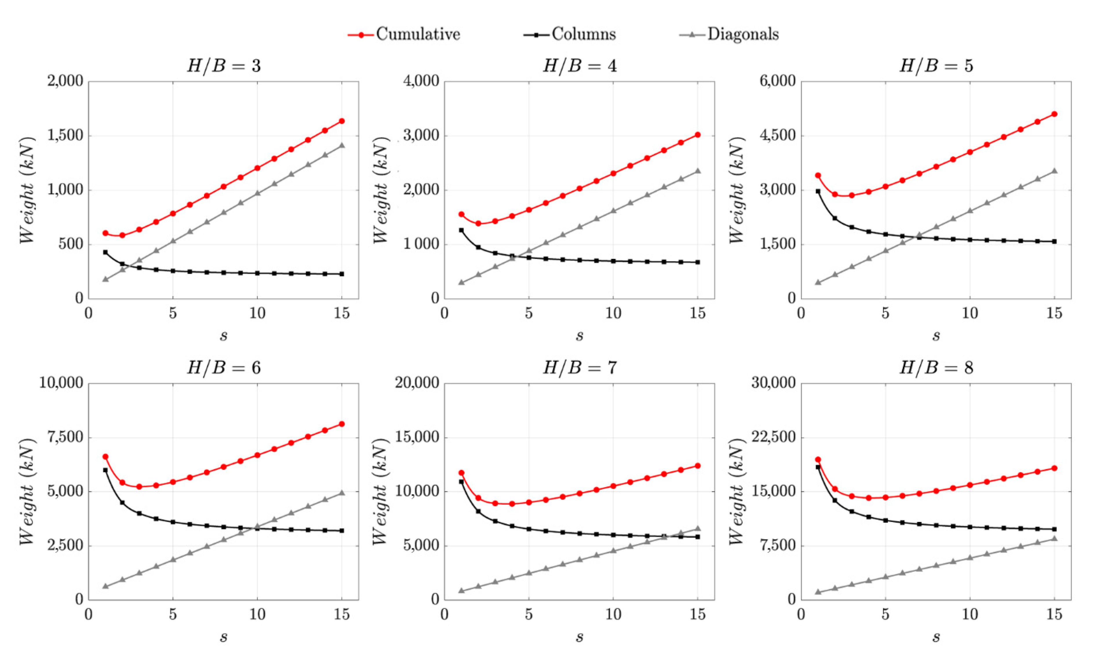
Figure 8 shows the trend of material consumption in the structural system as a function of the
values and different aspect ratios. The steel usage is expressed in terms of column weight (black lines), diagonal weight (gray lines) and cumulative weight (red lines) of the structural models. The results are in good agreement with those suggested by Moon et al. for braced tubes and diagrid structures. In fact, the deformation ratio that leads to the least amount of material usage directly depends on the aspect ratio: as building slenderness grows,
rises, while as building slenderness decreases,
reduces. This is consistent with the statement that short buildings, with low aspect ratios, behave more like shear beams, resulting in higher demands of shear deformation and increased size required for the diagonal members. In contrast, tall and slender buildings, with height
H/
B ratios, behave more like bending beams, entailing a greater demand for bending stiffness and leading to larger cross-sections required for the columns.
For the cumulative weight functions shown in
Figure 8 and additional case studies, up to a slenderness factor of 15, global minima are evaluated and plotted in
Figure 9a. Consequently, the stationary points obtained, corresponding to optimal
values (
) that produce the least steel consumption, are in turn interpolated by means of a linear regression. In
Figure 9b, the distribution of the optimal
values is plotted as a function of the aspect ratios. According to the parametric studies conducted, the following relationship is suggested:
The goodness of the regression in approximating the stationary points of the analyzed models is confirmed by the high coefficient of determination calculated (0.99). The proposed empirical relationship satisfactorily fits the real data and makes the adoption of Equation (21) effective in predicting the optimal values for the preliminary design. In conclusion, using for the calculation of the curvature and the shear strain , it is possible to define the required cross-sections for diagonals and columns by means of Equations (18) and (20). Hence, the preliminary relationships suggested have a twofold objective: to produce the lightest and most economical design and provide adequate stiffness requirements such as to limit the top displacement up to the design threshold of . It is necessary to highlight here that Equation (21) for the calculation of the optimal value only depends on the slenderness ratio of the building and it is not affected by the specific arrangement of diagonal members or the combination of multiple modules.
A further study is conducted to investigate the incidence of the bracing slope (
) on the structural behavior of the diagonal members. As it is easy to demonstrate, the plot of the shear stiffness as a function of the angle of inclination makes poor sense. This is because the best configuration to resist shear forces occurs when
is approximately null. Such statement is not surprising if one considers that the maximum shear rigidity is exhibited as the diagonal approaches a horizontal beam. Nevertheless, the geometrical configuration for very small values of
does not represent an optimal condition. It is possible to estimate, in fact, the best diagonal slope by focusing on a measure of the structural material employed (e.g., the overall weight of the structure) as a function of the changing angle. As clearly illustrated in
Figure 9c, the least amount of steel usage for tall buildings with tetrahedral-like modules and optimal
value is achieved as the angle nears 30–40°. Although the adoption of different bracing slopes does not affect the efficiency of the proposed sizing equations, this range of
values is highly recommended to reduce the total usage of steel and, in turn, the economic impact on the costs of construction.
To confirm the validity of the procedure for the preliminary design, as proposed in the previous sections, tetrahedral base modules with diagonal slope of 35° and base width of 15 m are sized according to the closed-form Equations (18) and (20) and optimal
values of Equation (21). The target displacements of the models are compared in
Table 1 with the outcomes provided by analyzing the structures with SAP2000. The top sway analytically derived is in perfect agreement with the numerical results.
4.2. Gravity Loads
In addition to the bending component of the wind action, also gravity loads insist on column members. For the sake of completeness, the occurrence of gravity plus wind loads is also evaluated for a complete assessment of the structural response. Dead and live loads give rise to a global downward force on the module (
Figure 6a) with gravity action on each column (
) given by:
where
is the vertical load acting on each base module and specified in Equation (1);
is the number of column members (namely the fixed number of triangular schemes for each floor), which is equal to 3 for the base module. The columns under the downward action are in compression, with axial stress equal to
. A preliminary estimation of the column cross-sections required to withstand the gravity action can be achieved through the same stiffness-based approach already investigated, without any loss of generalization. In other words, it is assumed that the overall stiffness required to resist the vertical forces, provided by both gravity load and bending counterpart of the wind, should be adequately determined to contain the share of the top target sway. Gravity loads acting on each column are added to the vertical action of the overturning couple due to the wind, in compliance with the directions of both actions. For the sake of brevity, intermediate calculations are omitted here but can be easily assessed by following the procedure described in detail in the previous section. The solution of the problem through the principle of virtual works allows determining the cumulative displacement produced by both the gravity load (
) and the bending component of the wind (
):
In conclusion, the preliminary cross-sections required to provide sufficient bending stiffness to the columns against vertical loads assumes the following complete form:
It is important to emphasize here that, although stiffness requirements are generally more stringent in the design of tall buildings, the structural model should also satisfy serviceability, strength, and stability criteria. The strength requirement is verified by limiting stresses, serviceability by limiting drifts, and stability by a sufficient factor of safety against buckling and P-Delta effects.
5. From Simple to Complex
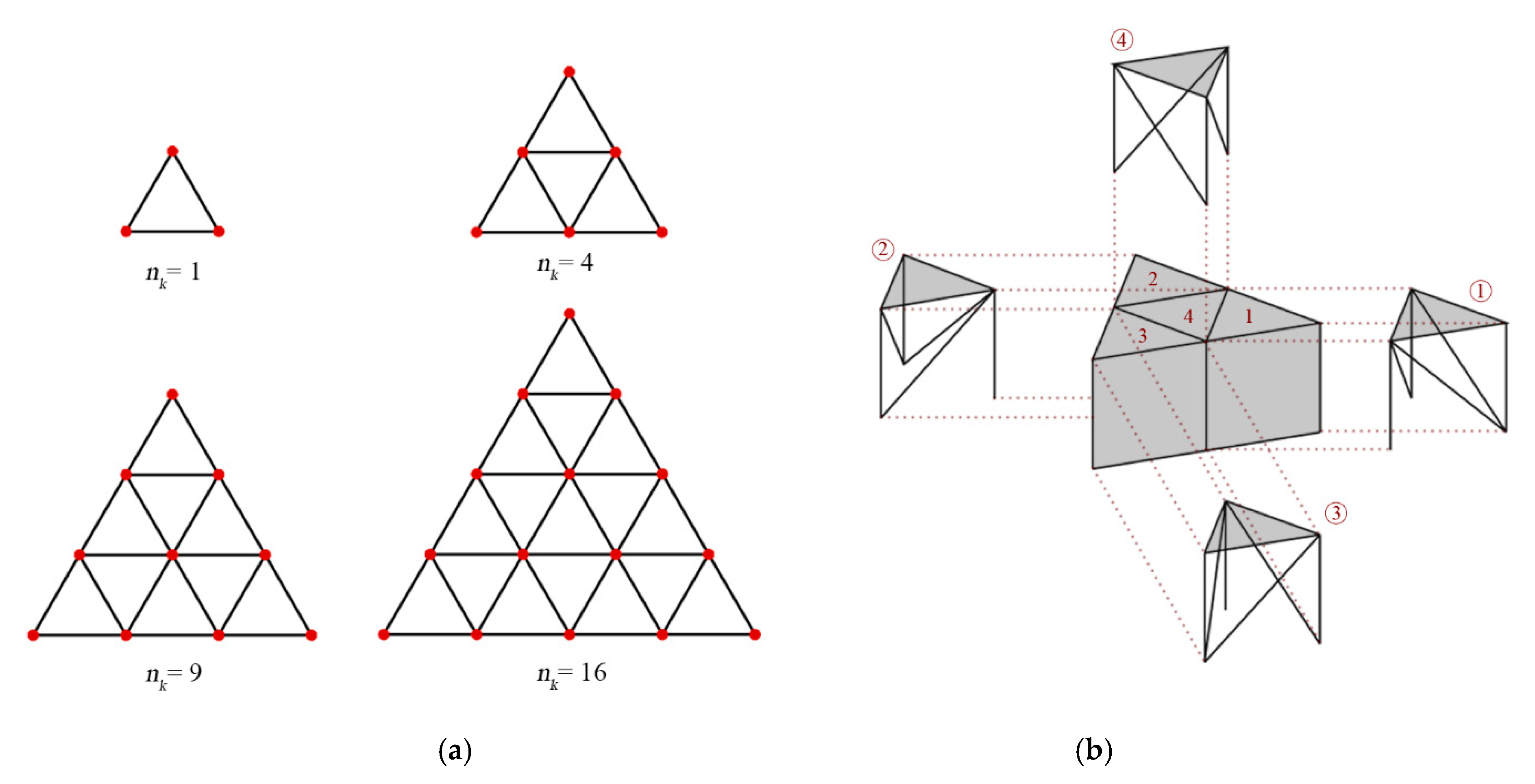
With the aim of proposing the new tetrahedral-based structural system for tall buildings, in this section some examples are considered among the manifold possible assemblies of the base modules. However, margins of applicability of the design proposal should not be considered limited to the cases investigated in this paper. In fact, the numerous modular possibilities that can be obtained from the arrangement of unit modules with triangular base, assembled in plan and elevation, cannot be exhaustively discussed here. ‘Complex arrangement’ means that it derives from assembled simpler units. Because such arrangements result from repetitions of the base modules, their mechanical behavior can, in turns, be evaluated on the basis of considerations of the structural performance of the elementary units. Complex configurations, resulting from the aggregation of multiple simplex modules juxtaposed next to each other, consist of, but are not limited to, triangular plans as shown in
Figure 10a. Three tetrahedral structural systems are derived by combining respectively 4, 9 and 16 base modules. The selection of the models is the result of design and feasibility assessments in the context of tall buildings, in order to reduce the obstruction of internal distributive spaces and obtain conventional footprint dimensions. Considering, for example, a typical width of 15 m for the base module, the assembly of 16 units produces a complete tetrahedral system with a triangular plan of 60 m width. In the following sections of this work reference is made to the ‘assembled unit’ to mean the aggregate configuration of several base modules in plan (
) and one base module along the elevation. ‘Assembled modules in elevation’ refer to multiple base modules arranged along the height of the building (
).
The multi-module arrangement within complex configurations deserves an in-depth description in order to suggest design recommendations on the applicability of the proposed procedure. The preliminary design equations derived in the previous section of this work are formulated with reference to the so-called Type 2 module (i.e., with two diagonal members converging in a single node). However, as already mentioned, the sizing equations are still to be considered valid also for the Type1 case, under the assumption of neglecting the contribution of the transversal diagonal, placed orthogonally to the barycentric loading force. The assembly procedure achieved through simple repetition of Type 2 models to generate complex triangular plans, as those illustrated in
Figure 10a, results in a strong wind-oriented response of the structural system. In other words, the tall building would behave differently due to changed orientations of the barycentric load. However, given the aleatory nature of the wind direction, a symmetry condition with respect to the lateral loads is highly desirable in order to provide the tall building with sufficient safety against random excitations. Based on this statement, an alternative combined strategy is illustrated in
Figure 10b and adopted in the following sections to formulate the design methodology of tetrahedral aggregates. The assembly procedure involves placing Type 2 units on the corners of the complex geometry (with two diagonals facing the centroid of the plan) and Type 1 modules juxtaposed in between. The different orientation of Type 2 modules together with the offset diagonals of Type 1, in fact, make the assembled system independent of the specific direction of the barycentric force. A further clarification is needed here about the presence of the transverse diagonal. This third diagonal cannot be neglected in the design of complex geometries, as its absence would undermine the principle of equivalent behavior of the structural system in the face of load orientations deviating from the design scenario. The following sections describe the design methodology for preliminary sizing of column and diagonal members, obtained from the combined juxtaposition of Type 1 and Type 2 modules.
5.1. Shear and Bending Stiffness of Assembled Modules
When several base modules are assembled in plan, shear forces due to wind load are counteracted by the axial action in the diagonal members only, in a regime of constant stress. As with the case of the single module, the axial stress of each member is proportioned to the number of active diagonals constituting the system. In fact, structural members located transversely with respect to the acting force have zero (or almost zero) axial stress and, therefore, do not provide a significant contribution to the global response of the structural system.
Table 2 shows the number of total diagonals (
) and active diagonals (
) within each analyzed assembly.
For assembled units not explicitly considered within the present work, the amount of total and active diagonals can be calculated through the following empirical equations, respectively, as a function of the number of total (3) and active braces (2) within each base module together with the number of aggregated units:
In detail, the number of active diagonals is derived by neglecting the contribution of transverse members to the global shear stiffness of the assembled structural system.
Assuming the closed-form Equation (18) of the unit module, the expression for the preliminary size of the diagonal cross-sections located at the
-th module and arranged in complex configurations is given by the following exact equation:
where
is the width of the unit module, which corresponds to
according to geometrical considerations;
is the design shear strain calculated by means of the optimal
value in Equation (21).
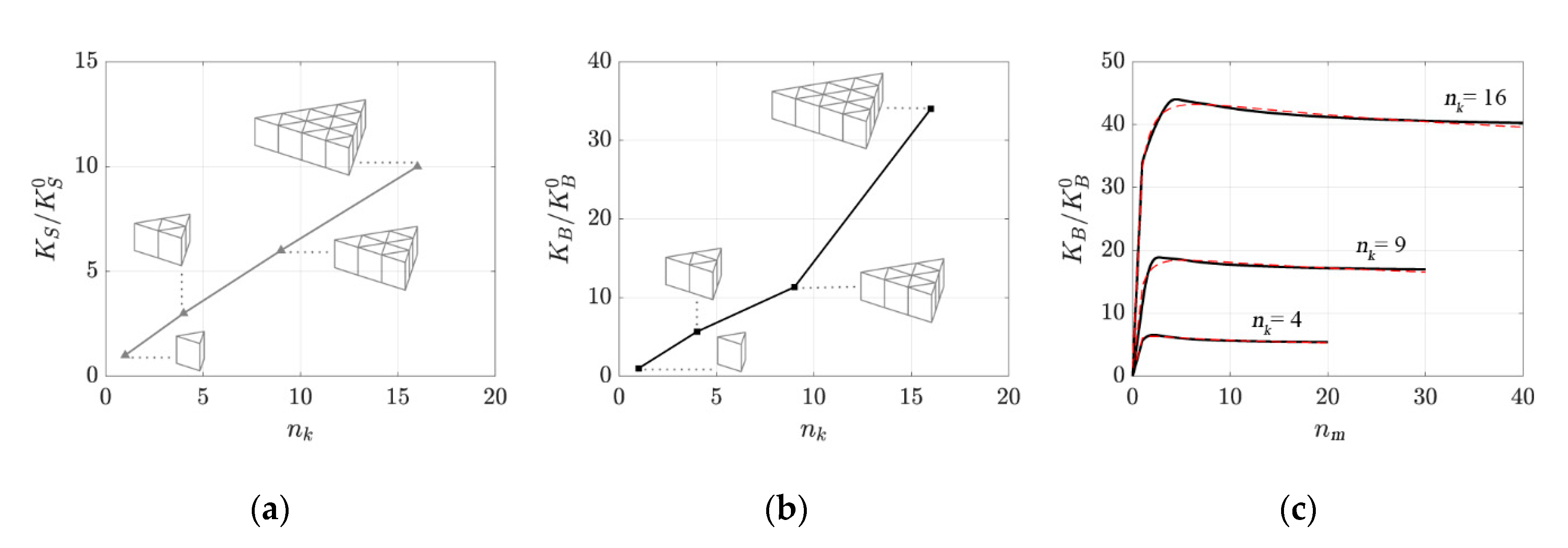
Figure 11a shows the trend of the shear stiffness of the aggregated units (
), normalized by the shear stiffness of the unit module (
). The shear stiffness of the assembled unit is derived from that of the base module through:
.
The clear separation of the contributions between columns and diagonals against the wind action fails in the case of bending moment when the modules are juxtaposed next to each other in plan. In fact, the structure tends to redistribute the axial forces more efficiently between vertical and diagonal members. The number of column member within each assembled unit is given by the following empirical expression:
where the constant value of 3 represents the number of column members within each base module.
The distribution of the flexural stiffness of the assembled units (
), normalized by the flexural stiffness of the unit module (
) for
can be appreciated in
Figure 11b. The reported non-linear trend prevents the bending stiffness from adopting a straightforward strategy such as the one proposed for the shear case. Furthermore, the number of resisting members participating in the global flexural response of the assembled units makes it impractical to define an exact closed-form solution of the problem. Therefore, an alternative strategy is presented here.
Figure 11c shows the trends of the normalized bending stiffness for different assembled units as the number of base modules changes along the building height. All the plots present a nonlinear path with quasi-constant values after reaching a certain threshold, which is closely related to the number of base modules aggregated in plan. Closed-form approximations of the stiffness ratios are proposed by recurring to the following functional form [
27]:
where the numerical values of the constants
,
,
and
are reported in
Table 3 and determined through a regression analysis intended to minimize the sum of squared residuals. To provide an effective support for the reader, standard deviation (SD) values, standard error (SE) values and coefficients of determination (R
2) are also included in the table.
By adopting the adimensional coefficient
for the assessment of the bending stiffness (
) and under the assumption that the overturning moment is resisted by columns only, Equation (20) proposed for the unit module can be considered reasonably acceptable also here. Therefore, the preliminary cross-section of the column members located at the
-th module and arranged in complex configurations is given by the following expression:
where
is the base of the unit module and
is the design flexural rate calculated by means of the optimal
value in Equation (21).
5.2. Numerical Studies
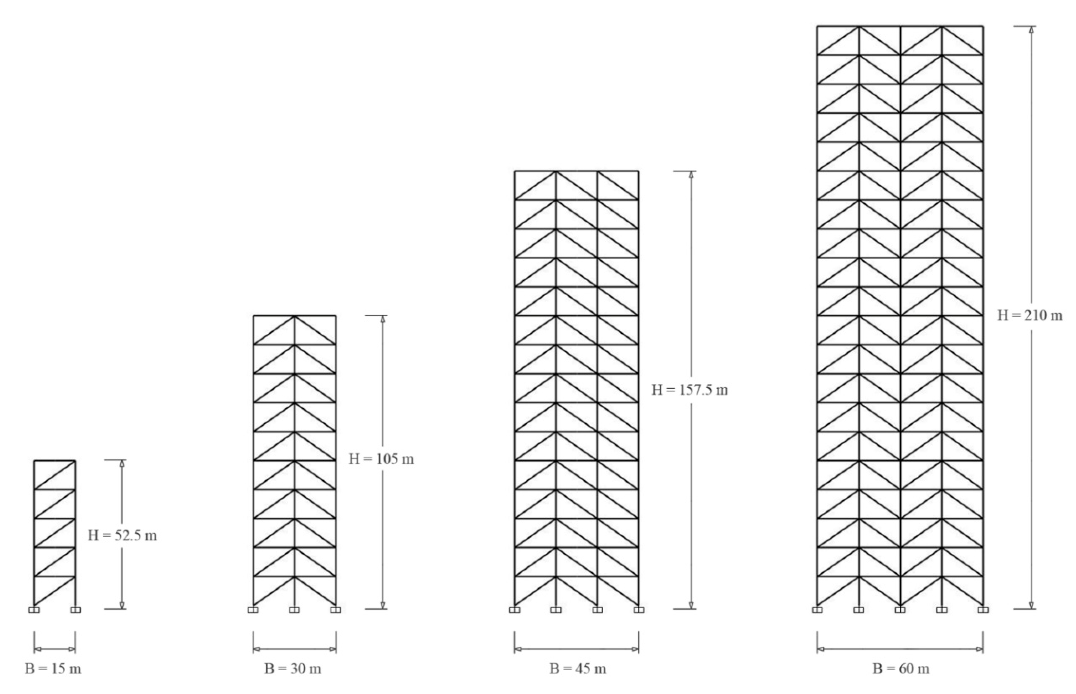
The design methodology presented in the preceding sections is applied to 52.5, 105, 157.5 and 210 m tall buildings (
Figure 12) with assembled tetrahedral units of 1, 4, 9 and 16 base modules, respectively, to have a constant height-to-width aspect ratio of 3.5. The base module of each complex configuration is 15 m width and 10.5 m height, with a diagonal slope of 35°. The triangular plans present widths of 15, 30, 45 and 60 m, respectively. The lateral wind action is reduced to unit point loads acting at the top of each module with a magnitude of 1000 kN. Each tetrahedral structure, creating the three-dimensional triangular pattern of the tall building, is made of steel members.
Using the stiffness-based approach proposed in Equations (26) and (29), diagonal and vertical member sizes are defined and subsequently tapered from the bottom module toward the top one for each complex configuration. The structures with this preliminary design are analyzed to assess their global behavior.
Table 4 provides information on the analyzed tetrahedral structures together with the lateral displacements, numerically calculated using SAP2000 (
). The error rates between the targeted top drifts (i.e.,
H/500) and the top displacements obtained using the preliminary methodology proposed are reasonably in close agreement, with a maximum percentile difference of almost 3%. This confirms the validity of the proposed methodology and it is concluded that the procedure is efficient for member sizing of tetrahedral-like structures for tall buildings at the preliminary design stage.
In conclusion, an alternative assembled system is explored to show margins of applicability of the proposed methodology. A brief discussion is reserved to the complex geometry obtained by juxtaposing only Type 1 base modules for tetrahedral-like structures. Under shear action, both cases of Type 1 plus Type 2 mixed units and uniform Type 1 units show diagonal members in a constant stress condition with the same values of axial stress and lateral displacement between the two geometries. This allows stating that the two multi-module structures exhibit equivalent shear stiffness, regardless of the specific bracing arrangement. Therefore, Equation (26) for the preliminary sizing of diagonal cross-sections can still be considered valid here. Conversely, under the bending action of wind, the aggregated units show coupled responses of diagonals and columns, with different distributions of axial stresses depending on the design diagonal layout. However, for tall buildings with the same geometric attributes shown in
Figure 12, the relative difference in lateral sway between the two assembly strategies is contained within acceptable limits, which increase as the number of base modules increases (upper bound of almost 1.0% for
= 16). Because the proposed preliminary procedure is based on the attainment of a fixed displacement threshold at the top of each module and since the displacement differences are very small, Equation (29) can be reasonably proposed even for complex geometries composed of uniform Type 1 modules.
6. Conclusions
Inspired by the high mechanical performance of diagrid structures, the minimization of material consumption on braced tubes and the expressive potency of tensegrity modular structures, this work proposes an innovative three-dimensional system for tall buildings. The new modular structural system is generated from the assembly of tetrahedral unit cells. In the proposed system, the base modules are provided with adequate stiffness to withstand both gravity and lateral loading scenarios and avoid large displacements at the top of the building, without relying on inner cores. In fact, the main advantage of the modular tetrahedral structure, compared to other resisting systems for tall buildings, lies in the potential rigidity offered by the three-dimensionality of the diagonal members and their plasticity in shaping the architectural space. Greater compositional freedom is envisaged given the potential elimination of any restriction on the distribution of internal spaces and/or vertical connections. The base module is defined based on preliminary evaluations of mechanical performance and repeatability requirements. Two unit cells with different diagonal arrangement are privileged: Type 1, derived from the tensegrity family, and Type 2. Judgments of convenience and simplicity elect this latter typology as the most suitable for assessing the decoupled (shear and flexural) behavior of the proposed tetrahedral-like structures under wind action.
A stiffness-based design methodology for determining preliminary member sizes for column and diagonal members is investigated and applied to a representative set of tall building models with single base modules. The results achieved in terms of targeted top displacement and required material consumption demonstrate the practical usefulness of the proposed preliminary design method. Empirical relationships for assessing the relative contribution of bending and shear deformation to the total lateral sway are derived by means of optimal values of the adimensional parameter , according to sustainability considerations. This study also examined the influence of the diagonal angle on the structural design. It is found that the angles ranging from about 30° to 40° are close to the optimal angle.
Numerical examples of tetrahedral systems composed of assembled mixed Type 1 and Type 2 units are also generated and preliminary equations for member sizing are assessed based on stiffness requirements. The results confirm that the preliminary methodology proposed in this work has good predictive capabilities in evaluating the structural design that employs the least amount of material while meeting design requirements. The implementation of multi-module geometries derived from the repetition of only Type 1 modules and only Type 2 modules is also discussed. Alternative configurations accounting for other base modules or other complex assemblies would require further studies. However, for 3-diagonal modules that do not fall within those explicitly specified in this work, it is possible, with a good level of approximation, to adopt the suggested design procedure and assume the proposed preliminary sizes for columns and braces as initial attempt values. Strength, stability, and displacement checks are, nonetheless, strongly recommended.
It should be emphasized here that this work represents an initial attempt to the investigation of tetrahedral patterns for tall buildings. With the aim of proposing this new structural system, the paper illustrates and concentrates on some of the manifold possible assemblies of the base modules. However, margins of applicability should not be considered exhaustively limited to the cases studied within this work. Further insights will be also addressed to buckling and torsional effects in order to acquire a comprehensive knowledge of the mechanical performance of the proposed tetrahedral system.
Author Contributions
Conceptualization, G.A., F.M., R.T.; methodology, G.A., F.M.; software, G.A., R.T.; validation, G.A.; formal analysis, G.A.; investigation, G.A., R.T.; resources, F.M.; data curation, G.A.; writing—original draft preparation, G.A.; writing—review and editing, G.A.; supervision, G.A., F.M.; project administration, F.M.; funding acquisition, F.M. All authors have read and agreed to the published version of the manuscript.
Funding
This work was supported by the Italian Ministry of Education, University and Research (MIUR).
Acknowledgments
The authors would like to express their gratitude to the architect Tommaso Valle for his contribution in defining the architectural design of the tall building.
Conflicts of Interest
The authors declare no conflict of interest.
References
- Scaramozzino, D.; Lacidogna, G.; Carpinteri, A. New Trends towards Enhanced Structural Efficiency and Aesthetic Potential in Tall Buildings: The Case of Diagrids. Appl. Sci. 2020, 10, 3917. [Google Scholar] [CrossRef]
- Mele, E.; Fraldi, M.; Montuori, G.M.; Perrella, G. Non-conventional Structural Patterns for Tall Buildings: From Diagrid to Hexagrid and Beyond. In Proceedings of the Fifth International Workshop on Design in Civil and Environmental Engineering, Sapienza University of Rome Representative, Rome, Italy, 6–8 October 2016. [Google Scholar]
- Angelucci, G.; Mollaioli, F. Voronoi-Like Grid Systems for Tall Buildings. Front. Built Environ. 2018, 4, 78. [Google Scholar] [CrossRef]
- Moon, K.-S.; Connor, J.J.; Fernandez, J.E. Diagrid structural systems for tall buildings: Characteristics and methodology for preliminary design. Struct. Des. Tall Spéc. Build. 2007, 16, 205–230. [Google Scholar] [CrossRef]
- Montuori, G.M.; Mele, E.; Brandonisio, G.; De Luca, A. Design criteria for diagrid tall buildings: Stiffness versus strength. Struct. Des. Tall Spéc. Build. 2013, 23, 1294–1314. [Google Scholar] [CrossRef]
- Montuori, G.M.; Mele, E.; Brandonisio, G.; De Luca, A. Geometrical patterns for diagrid buildings: Exploring alternative design strategies from the structural point of view. Eng. Struct. 2014, 71, 112–127. [Google Scholar] [CrossRef]
- Angelucci, G.; Mollaioli, F. Diagrid structural systems for tall buildings: Changing pattern configuration through topological assessments. Struct. Des. Tall Spéc. Build. 2017, 26, e1396. [Google Scholar] [CrossRef]
- Tomei, V.; Imbimbo, M.; Mele, E. Optimization of structural patterns for tall buildings: The case of diagrid. Eng. Struct. 2018, 171, 280–297. [Google Scholar] [CrossRef]
- Lacidogna, G.; Nitti, G.; Scaramozzino, D.; Carpinteri, A. Diagrid systems coupled with closed- and open-section shear walls: Optimization of geometrical characteristics in tall buildings. Procedia Manuf. 2020, 44, 402–409. [Google Scholar] [CrossRef]
- Carpinteri, A.; Lacidogna, G.; Nitti, G. Open and closed shear-walls in high-rise structural systems: Static and dynamic analysis. Curved Layer. Struct. 2016, 3, 154–171. [Google Scholar] [CrossRef] [Green Version]
- Nitti, G.; Lacidogna, G.; Carpinteri, A. Tall buildings subjected to horizontal loading: Analysis of two case studies by an in-house numerical code. In Proceedings of the 23rd Conference of the Italian Association of Theoretical and Applied Mechanics (AIMETA 2017), Salerno, Italy, 4 September 2017. [Google Scholar]
- Nitti, G.; Lacidogna, G.; Carpinteri, A. Structural Analysis of High-rise Buildings under Horizontal Loads: A Study on the Piedmont Region Headquarters Tower in Turin. Open Constr. Build. Technol. J. 2019, 13, 81–96. [Google Scholar] [CrossRef] [Green Version]
- Li, X.-P.; Zhao, L.-Y.; Liu, Z.-Z. Topological Optimization of Continuum Structure based on ANSYS. MATEC Web Conf. 2017, 95, 7020. [Google Scholar] [CrossRef] [Green Version]
- Stromberg, L.L.; Beghini, A.; Baker, W.F.; Paulino, G.H. Topology optimization for braced frames: Combining continuum and beam/column elements. Eng. Struct. 2012, 37, 106–124. [Google Scholar] [CrossRef]
- Angelucci, G.; Mollaioli, F.; Alshawa, O. Evaluation of optimal lateral resisting systems for tall buildings subject to horizontal loads. Procedia Manuf. 2020, 44, 457–464. [Google Scholar] [CrossRef]
- Beghini, L.L.; Beghini, A.; Katz, N.; Baker, W.F.; Paulino, G.H. Connecting architecture and engineering through structural topology optimization. Eng. Struct. 2014, 59, 716–726. [Google Scholar] [CrossRef]
- Angelucci, G.; Spence, S.M.; Mollaioli, F. An integrated topology optimization framework for three-dimensional domains using shell elements. Struct. Des. Tall Spéc. Build. 2020. [Google Scholar] [CrossRef]
- Gilewski, W.; Kłosowska, J.; Obara, P. Applications of Tensegrity Structures in Civil Engineering. Procedia Eng. 2015, 111, 242–248. [Google Scholar] [CrossRef] [Green Version]
- Sultan, C.; Skelton, R. Deployment of tensegrity structures. Int. J. Solids Struct. 2003, 40, 4637–4657. [Google Scholar] [CrossRef]
- Froli, M.; Laccone, F. Static Concept for Long-Span and High-Rise Glass Structures. J. Arch. Eng. 2018, 24, 04017030. [Google Scholar] [CrossRef]
- Froli, M.; Laccone, F. Hybrid GLAss-Steel Stele (HYGLASS): Preliminary Mechanical Study on a Smart Tetrahelical Cantilevering Tall Structure. In Proceedings of the Challenging Glass 6—Conference on Architectural and Structural Applications of Glass, Delft, The Netherlands, 17–18 May 2018. [Google Scholar] [CrossRef]
- Pandian, N.K.; Ananthasuresh, G.K. Synthesis of tensegrity structures of desired shape using constrained minimization. Struct. Multidiscip. Optim. 2017, 56, 1233–1245. [Google Scholar] [CrossRef]
- Xu, X.; Wang, Y.; Luo, Y. Finding member connectivities and nodal positions of tensegrity structures based on force density method and mixed integer nonlinear programming. Eng. Struct. 2018, 166, 240–250. [Google Scholar] [CrossRef]
- Liu, K.; Paulino, G.H. Tensegrity topology optimization by force maximization on arbitrary ground structures. Struct. Multidiscip. Optim. 2019, 59, 2041–2062. [Google Scholar] [CrossRef]
- Nanayakkara, K.I.U.; He, L.; Fairclough, H.E.; Gilbert, M. A simple layout optimization formulation for load-carrying tensegrity structures. Struct. Multidiscip. Optim. 2020, 62, 2935–2949. [Google Scholar] [CrossRef]
- Moon, K.S. Stiffness-based design methodology for steel braced tube structures: A sustainable approach. Eng. Struct. 2010, 32, 3163–3170. [Google Scholar] [CrossRef]
- Alshawa, O.; Angelucci, G.; Mollaioli, F.; Quaranta, G. Quantification of Energy-Related Parameters for Near-Fault Pulse-Like Seismic Ground Motions. Appl. Sci. 2020, 10, 7578. [Google Scholar] [CrossRef]
Figure 1.
Rendering views of an applicative example of the tetrahedral structural system in the design of a tall building.
Figure 1.
Rendering views of an applicative example of the tetrahedral structural system in the design of a tall building.
Figure 2.
Application of the proposed tetrahedral-like modules in the design of a tall building.
Figure 2.
Application of the proposed tetrahedral-like modules in the design of a tall building.
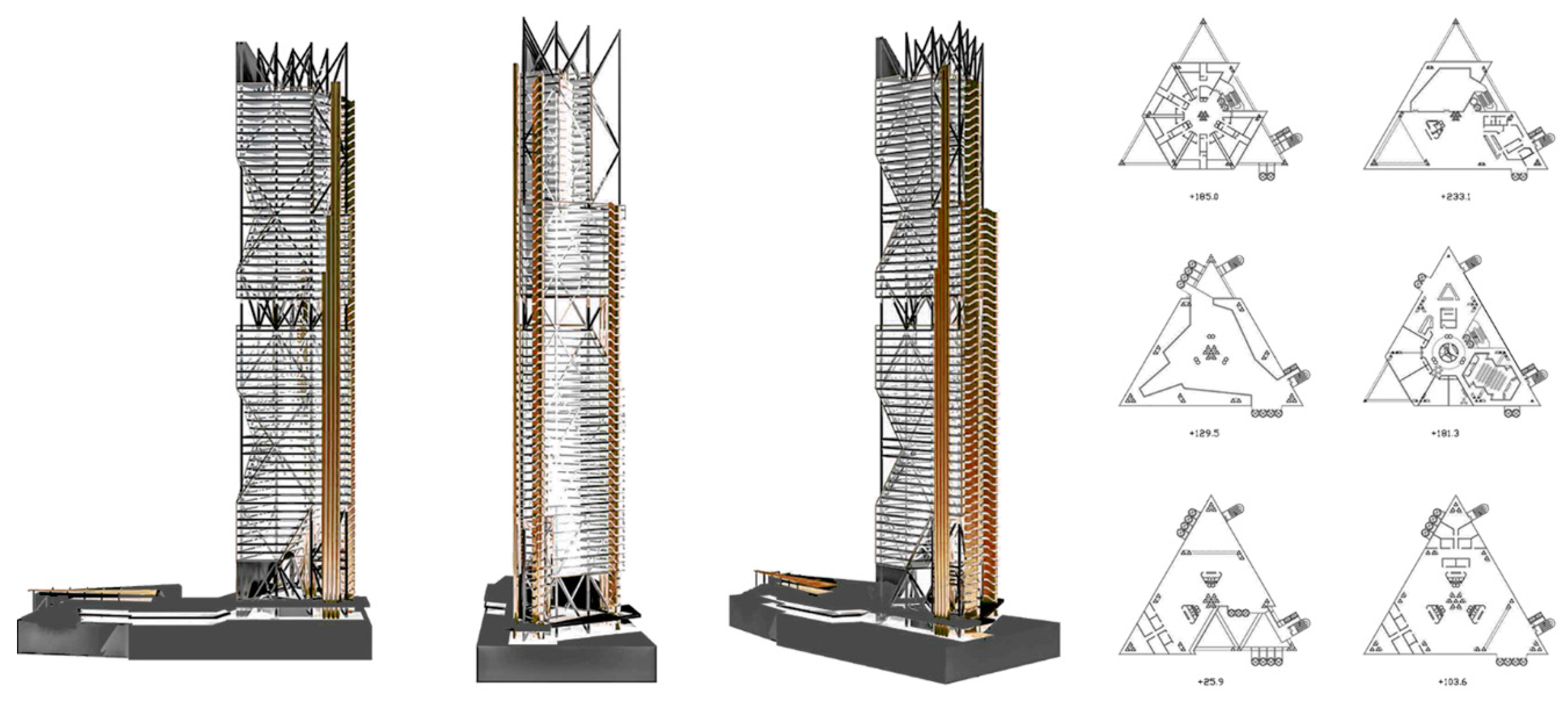
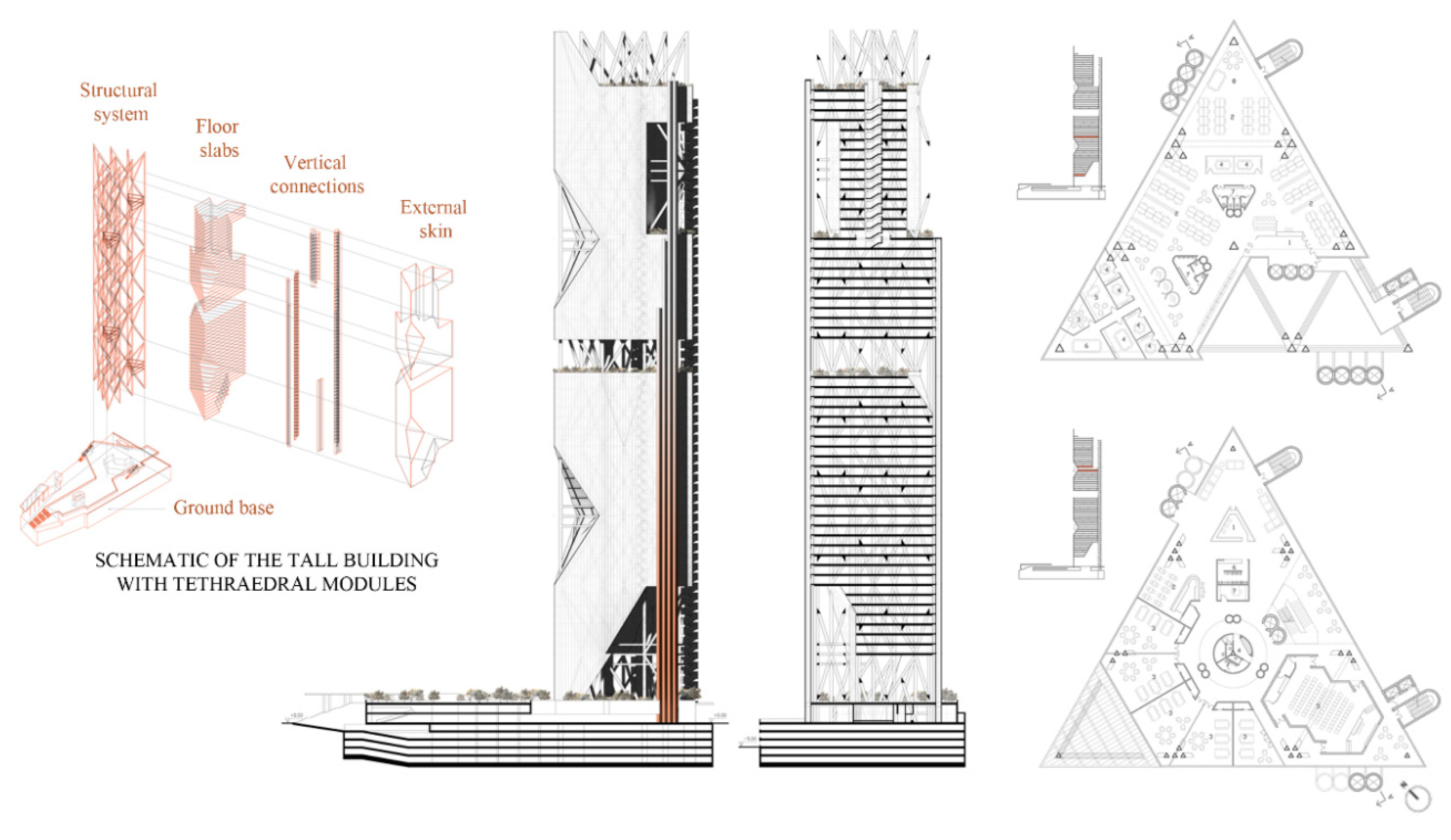
Figure 3.
Schematic of the tall building system, front view, section view and typical floor distributions of the architectural model.
Figure 3.
Schematic of the tall building system, front view, section view and typical floor distributions of the architectural model.
Figure 4.
Schematic of the tall building with the proposed tetrahedral-like structural system: constitutive elements (a) and base modules (b).
Figure 4.
Schematic of the tall building with the proposed tetrahedral-like structural system: constitutive elements (a) and base modules (b).
Figure 5.
Schematic of the tetrahedral base modules (Type 1 and Type 2) with geometric characterization.
Figure 5.
Schematic of the tetrahedral base modules (Type 1 and Type 2) with geometric characterization.
Figure 6.
Schematic of the Type 2 base module subjected to gravity load (a), overturning moment (b) and shear force (c). Orange and blue colors provide information on the axial stresses in the members: compression and tension, respectively.
Figure 6.
Schematic of the Type 2 base module subjected to gravity load (a), overturning moment (b) and shear force (c). Orange and blue colors provide information on the axial stresses in the members: compression and tension, respectively.
Figure 7.
Undeformed and deformed configurations due to shear and bending counterparts of the wind load.
Figure 7.
Undeformed and deformed configurations due to shear and bending counterparts of the wind load.
Figure 8.
Material consumption of tetrahedral-like structures for increasing aspect ratios and different ‘s’ values.
Figure 8.
Material consumption of tetrahedral-like structures for increasing aspect ratios and different ‘s’ values.
Figure 9.
Minimum weight provided by the analyzed models with different aspect ratios (a). Distribution of the optimal s values (red circles) as a function of the building slenderness and linear approximation (black line) (b). Distribution of the optimal angle for base modules assembled along the building elevation (c).
Figure 10.
(a) Base module and analyzed configurations of assembled units, achieved through the aggregation of 4, 9 and 16 base modules, respectively. (b) Assembled geometry of 4 mixed base modules for tetrahedral-like structural systems.
Figure 10.
(a) Base module and analyzed configurations of assembled units, achieved through the aggregation of 4, 9 and 16 base modules, respectively. (b) Assembled geometry of 4 mixed base modules for tetrahedral-like structural systems.
Figure 11.
Distribution of the normalized shear (a) and bending stiffness (b) of the complex configurations for nm = 1 with respect to the number of aggregated modules in plan. Trends of the mean curves (black lines) and approximating functions (red dashed lines) for different assembled units with respect to the building elevation (c).
Figure 12.
Schematic of the analyzed models consisting of assembled units of tetrahedral systems.
Figure 12.
Schematic of the analyzed models consisting of assembled units of tetrahedral systems.
Table 1.
Comparison between the target top drifts and the displacements computed with SAP2000.
Table 1.
Comparison between the target top drifts and the displacements computed with SAP2000.
| H | nm = H/B | sopt | utarget = H/500 | usap |
|---|
| (-) | (-) | (-) | (m) | (m) |
| 31.5 | 2.1 | 1.10 | 0.063 | 0.063 |
| 42.0 | 2.8 | 1.46 | 0.084 | 0.084 |
| 52.5 | 3.5 | 1.83 | 0.105 | 0.105 |
| 63.0 | 4.2 | 2.19 | 0.126 | 0.126 |
| 73.5 | 4.9 | 2.56 | 0.147 | 0.147 |
| 84.0 | 5.6 | 2.93 | 0.168 | 0.168 |
Table 2.
Definition of the diagonal members.
Table 2.
Definition of the diagonal members.
| nk | nd | nd,act |
|---|
| (-) | (-) | (-) |
| 1 | 3 | 2 |
| 4 | 9 | 6 |
| 9 | 18 | 12 |
| 16 | 30 | 20 |
Table 3.
Results of the regression analyses.
Table 3.
Results of the regression analyses.
| nm | nc | a1 | a2 | a3 | a4 | SD | SE | R2 |
|---|
| 4 | 6 | 0.15 | 6.18 | 2.11 | 1.13 | 0.52 | 0.04 | 0.91 |
| 9 | 10 | 0.12 | 18.32 | 5.37 | 1.12 | 1.22 | 0.07 | 0.73 |
| 16 | 15 | 1.30 | 41.91 | 6.64 | 1.09 | 2.46 | 0.12 | 0.90 |
Table 4.
Comparison between analytical and numerical results in terms of top displacement.
Table 4.
Comparison between analytical and numerical results in terms of top displacement.
| H | B | nk | nm | ck | utarget | usap | Error |
|---|
| (m) | (m) | (-) | (-) | (-) | (m) | (m) | (%) |
| 52.5 | 15 | 1 | 5 | 1 | 0.105 | 0.105 | - |
| 105.0 | 30 | 4 | 10 | 7.2 | 0.210 | 0.207 | 1.35 |
| 157.5 | 45 | 9 | 15 | 17.6 | 0.315 | 0.306 | 2.74 |
| 210.0 | 60 | 16 | 20 | 41.5 | 0.420 | 0.415 | 1.18 |
| Publisher’s Note: MDPI stays neutral with regard to jurisdictional claims in published maps and institutional affiliations. |
© 2020 by the authors. Licensee MDPI, Basel, Switzerland. This article is an open access article distributed under the terms and conditions of the Creative Commons Attribution (CC BY) license (http://creativecommons.org/licenses/by/4.0/).


