Article

Residual Stress, Microstructure and Mechanical Properties in Thick 6005A-T6 Aluminium Alloy Friction Stir Welds

1
Department of Nuclear Physics, China Institute of Atomic Energy, Beijing 102413, China
2
CRRC Changchun Railway Vehicles Co. Ltd., Changchun 130000, China
3
Helmholtz-Zentrum Berlin für Energie und Materialien, Hahn Meitner Platz 1, 14109 Berlin, Germany
4
Shanxi Key Laboratory of Friction Welding Technologies, School of Materials Science and Engineering, Northwestern Polytechnical University, Xi’an 710072, China
5
Department of Mechanical and Electrical Engineering, Central South University, Changsha 410083, China
6
State Key Laboratory of Tribology, Department of Mechanical Engineering, Tsinghua University, Beijing 100084, China
*
Author to whom correspondence should be addressed.
These authors contributed equally to this work and should be considered as co-first authors.
Metals 2019, 9(7), 803; https://doi.org/10.3390/met9070803
Submission received: 3 July 2019 / Revised: 17 July 2019 / Accepted: 18 July 2019 / Published: 21 July 2019
(This article belongs to the Special Issue Characterization of Welded Joints)

Abstract

:
Plates (37 mm thick) of 6005A-T6 aluminum alloy were butt joined by a single-sided and double-sided friction stir welding (FSW). The 3D residual stresses in the joints were determined using neutron diffraction. The microstructures were characterized by a transmission electron microscope (TEM) and electron backscatter diffraction (EBSD). In the single-sided FSW specimen, there were acceptable mechanical properties with a tensile strength of 74.4% of base metal (BM) and low residual stresses with peak magnitudes of approximately 37.5% yield strength of BM were achieved. The hardness is related to the grain size of the nugget zone (NZ), and in this study, precipitations were dissolved due to the high heat input. In the double-sided FSW specimen, there were good mechanical properties with a tensile strength of 80.8% of BM, but high residual stresses with peak magnitudes of approximately 70% yield strength of BM were obtained. The heat input by the second pass provided an aging environment for the first-pass weld zone where the dissolved phases were precipitated and residual stresses were relaxed.

1. Introduction

Aluminium alloy 6005A, a β-precipitation (Mg2Si) strengthened heat treatable alloy, is widely used in rail transportation industries due to its excellent corrosion resistance and extrusion characteristics [1,2]. The welding joints to connect the extruded sheets and plates are usually the weak regions since the welding heat input introduces the microstructural changes deteriorating the mechanical properties and residual stresses causing fatigue cracks and stress-induced corrosion [3,4]. Therefore, sound welding is required to join extruded aluminium alloy sheets and plates.
Friction stir welding is a solid-state joining technique, which involves both plastic and thermal deformations [5,6]. In this process, process parameters, such as tool rotation and traverse speeds, need to be optimized to get good quality joints. The effect of tool rotation and traverse speeds, on microstructural changes and residual stresses of friction stir welding (FSW) aluminium alloys, have been studied widely [1,2,3,4,7,8,9,10,11,12,13,14,15,16,17,18,19,20,21,22,23,24,25,26,27,28,29,30,31,32,33,34]. Simar et al. reported that the β’’ originally present in the base metal (BM) fully dissolved in the nugget zone (NZ) and coarsened in the heat affected zone (HAZ) of 6005A-T6 aluminium FSW joint [1]. They also explained the softened region around the weld center. Dong et al. studied the effect of welding speed on microstructures and the mechanical properties of 6005A-T6FSW joints, reporting an increased tendency of tensile properties with increasing the welding speed [4]. Wang et al. concluded that the 6061-T6 aluminum FSW joints made at low welding speed exhibited lower residual stress, due to a change in microstructure and stress relaxation that occurred as a result of the longer heating time associated with the low welding speed [8]. Therefore, microstructure, mechanical properties and residual stresses should be considered together to obtain the optimized FSW process. However, most studies have focused on the effects of welding speed and rotation speed on either microstructures and mechanical properties, or residual stresses in aluminium sheets and thin plates.
Nonetheless, FSW has been applied to the production of large prefabricated aluminium panels in high speed railcars, which helps to reduce the weight and improve the integrity of aluminium sheets. To join thick 6005A aluminium plates using FSW, a better understanding of residual stresses and microstructure is required. However, the residual stresses and microstructures have not been studied in thick 6005A-T6 aluminium alloy plates joined by single-sided and double-sided FSW.
Among the methods of residual stress measurement, neutron diffraction can nondestructively characterize the 3D residual stress distribution of engineering materials [35,36]. The deep penetration capability of neutrons into most metallic materials makes neutron diffraction a powerful tool for determining residual stresses through welds. The E3 residual stress diffractometer at HZB is one such high-performance neutron residual stress instrument, capable of experimental measurement of 3D residual stress distributions [37]. This instrument was chosen to characterize the residual stresses in thick 6005A-T6 aluminium alloy FSWs.
In this work, thick 6005A-T6 aluminium alloy plates (37 mm thick) were studied to determine the single-sided and double-sided FSW residual stress distributions using neutron diffraction. In addition, microstructures and mechanical properties were studied to characterize welding behavior. This experimental study was carried out to understand the 3D residual stress distributions and microstructural changes. This study can be helpful in the design of welding strategies.

2. Experimental Details

2.1. Materials

The base metal used in this investigation was 37 mm thick 6005A-T6 aluminium alloy with the chemical composition and mechanical properties shown in Table 1. The dimensions of the 6005A-T6 test plates are shown in Figure 1.
Further, FSW was carried out on a LM-FSW-5025 machine (China FSW Center, Beijing, China). For the single-sided FSW, the tool consisted of a 35 mm diameter shoulder with a pin length of 36.5 mm and a root diameter of 18 mm. The single-sided FSW process was performed with a rotation speed of 350 rpm and a traverse speed of 40 mm/min. The down force was approximately 8–9 kN. For the double-sided FSW, the tool consisted of a 32 mm diameter shoulder with a pin length of 18 mm and a root diameter of 14.4 mm. To apply the second pass of the FSW, the plates were rotated around their welding axes after completing the first weld. All welding passes were conducted with a rotation speed of 650 rpm and a traverse speed of 200 mm/min. The down force was approximately 13–14 kN.
The temperature of the NZ was estimated using the following relation [38]:
T T m = K   ( w 2 v × 10 4 ) α
where Tm is the melting temperature of 6005A aluminium alloy 654 °C, exponent α is a dimensionless constant selected as 0.05, K is a dimensionless constant selected as 0.7, ν is the traverse speed and ω is the rotation speed [39]. According to Equation (1), the temperature of the nugget zone in the single-sided FSW is 431.4 °C, while in the double-sided, FSW is 423.5 °C.

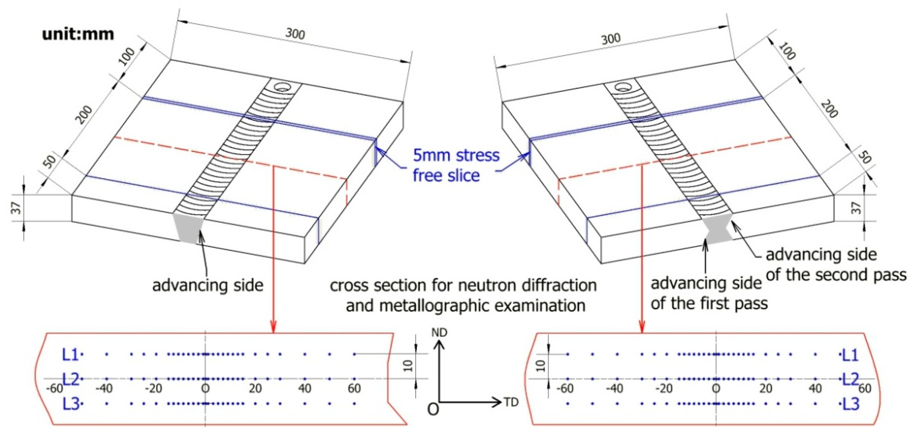
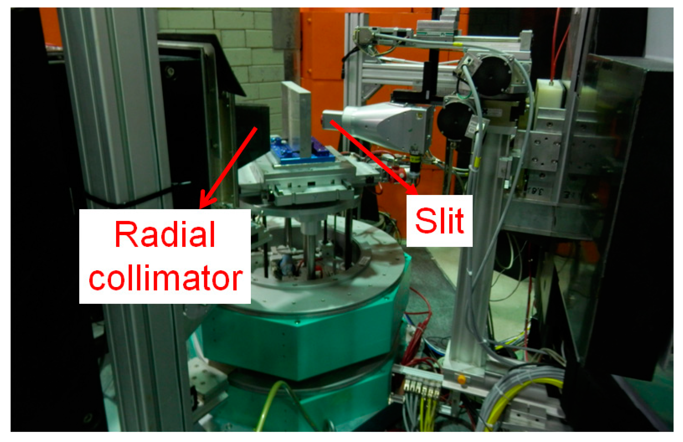
2.2. Neutron Diffraction

Due to the high penetration ability of thermal neutrons, neutron diffraction is an excellent engineering tool for providing 3D residual stresses nondestructively in bulk components. Therefore, neutron diffraction was applied to characterize the residual stresses in thick 6005A-T6 aluminium alloy FSWs, and was performed on the dedicated residual stress neutron diffractometer E3 at HZB, Germany.
As shown in Figure 1, the middle section with 200 mm in length was cut using electrical discharge machining (EDM, LA350, SSG, Suzhou, China) from the specimen for a neutron diffraction measurement. The longitudinal direction (LD), transverse direction (TD) and normal direction (ND) were assumed to be the principal directions in the bulk of the components and were measured as three orthogonal directions. The points along three lines, L1, L2 and L3, in the cross section were chosen to characterize the residual stresses, as shown in Figure 1. The diffraction peaks of the marked points were measured with the scattering vector parallel to three orthogonal directions. The peak positions, 2θ, were analyzed using the least square Gaussian fitting method [40].
The measurements were made using the Al(311) Bragg reflection, which is the strongest diffraction reflection and also is weakly affected by intergranular strains [36]. The E3 is equipped with a perfectly bent Si(400) crystal monochromator providing a wavelength of 1.47Å. Therefore, the Al(311) reflection was at a scattering angle of 2θ~74°. Figure 2 shows the experimental setup on E3 for the measurement of the transverse component. The gauge volume was defined by an incident primary slit with 3 mm and a secondary radial collimator with 2 mm. The height of the primary slit was set to 10 mm for transverse and normal measurements, and 3 mm for longitudinal measurements.
The elastic lattice strains εi in the i-direction (i = LD, TD, ND) were calculated using the following equation [36]:
ε i = d i d 0 d 0
The elastic strains were converted to residual stresses (σLD, σTD, σND) using the generalized Hooke’s law [36]:
σ i = E h k l 1 + v h k l [ ε i + v h k l 1 2 v h k l   ( ε LD + ε TD + ε ND ) ]
where i is the LD, TD or ND component corresponding to the three orthogonal directions. The diffraction elastic constants (E311) of 69 GPa and Poisson’s ratio (ν311) of 0.35 were computed using the Kröner model via the software, IsoDEC [41].
To obtain a precise stress-free reference lattice parameter, d0, is an important part of the diffraction-based, residual strain/stress experiment. To address a possible issue of d0 variation due to microstructural changes, a full stress analysis was performed on 5-mm slices made by EDM from the specimen. The measurements were repeated in the same positions as for the specimen. Then, in an approximation of a biaxial stress state and the condition of the through thickness component (longitudinal in this case) to be zero ( σ L D = 0 ), the calculation of the stress-free parameters was made according to the following equation:
d 0 = 1 v h k l 1 + v h k l d LD + v h k l 1 + v h k l ( d TD + d ND )
As well as the TD and ND stress components in the slice as a by-product of the analysis,
σ TD = E h k l 1 + v h k l [ ε TD ε LD ] ,   σ ND = E h k l 1 + v h k l [ ε ND ε LD ] .

2.3. Microstructure Characterization

The metallographic samples were cut perpendicular to the welding direction using EDM to avoid thermal degradation. The optical microstructure examination was performed on an Olympus microscope.
In order to compare the difference in precipitation, the microstructure examination in the NZ was conducted by a transmission electron microscope (TEM, Tecnai G2 F20, FEI, Hillsboro, OR, USA). The metallographic samples were polished down to a thickness of 80~100 μm. The final thickness reduction was obtained by electro-polishing with a HNO3 solution (HNO3 30% in volume in methanol at ~30 °C under 9V).
The electron backscatter diffraction (EBSD) samples were examined in a high resolution Philips XL30 field emission gun (FEG) SEM (Philips, Amsterdam, The Netherlands) interfaced to an HKL Channel EBSD orientation mapping system. The resulting EBSD orientation maps, with a step size of 0.1–0.25 μm and an area of 145 × 127 μm, were used to characterize the grain structures present in the NZ at three positions on cross sections along the weld center line, namely, the top (10 mm above the mid plane), the center (at the mid plane), and the bottom of the nugget (10 mm below the mid plane). The maps were processed using in house software (VMap) to determine the grain size.

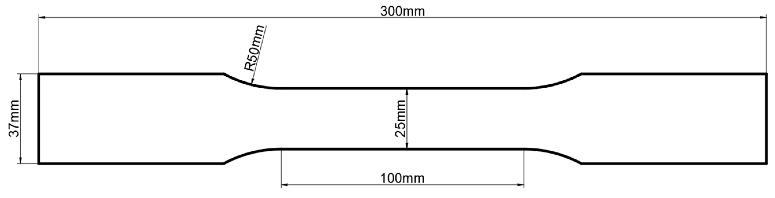
2.4. Mechanical Properties

The hardness tests were performed using the Vicker hardness method, using a load of 500 g applied for 10 s. Three lines were chosen on the transverse section of the welds with a distance of 1 mm between neighboring measured points, as shown in Figure 1. The specimens were cut to 3-mm slices to release the residual stress, which minimized the influence of residual stress on the hardness test.
The tensile tests on welded specimens were performed on the transverse, i.e., perpendicular to the welding direction. Eight samples were cut using EDM from the single-sided FSW and double-sided FSW. The transverse cross-section of the tensile samples is shown in Figure 3. These tensile samples were 25 mm thick, 6 mm wide and 200 mm long, with an initial gauge length of 100 mm. The tensile test was carried out on a universal electronic tensile testing machine (MTS Landmark) with a crosshead moving speed of 2 mm/min. The range of load cell is ±100 KN.

3. Results and Discussion

Heat-treatable aluminium alloys derive much of their strength from the presence of fine precipitates. As residual stresses and microstructures are of great significance in determining weld performance, they were studied together for thick 6005A-T6 aluminium alloy FSWs.

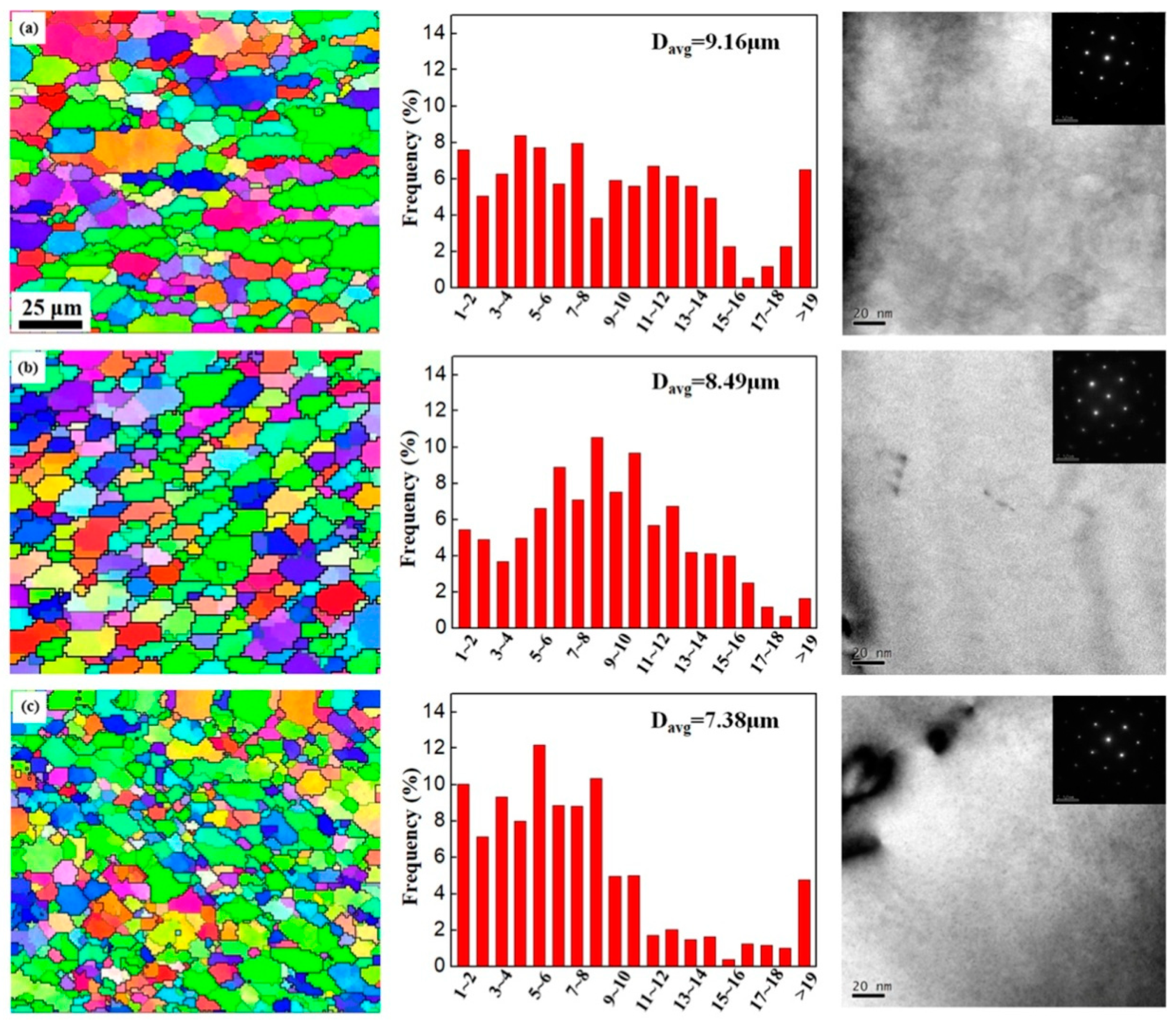
3.1. Microstructural Evolution

Figure 4 shows the macrostructure of the 6005A-T6 single-sided and double-sided FSW joints. The NZ, thermo-mechanically affected zone (TMAZ), HAZ and BM are divided by the dotted lines. The TMAZ is more optically distinct on the advancing side and more diffuse on the retreating side in both specimens. The microstructures, including grain size and precipitation at the marked positions in Figure 4, are discussed further.

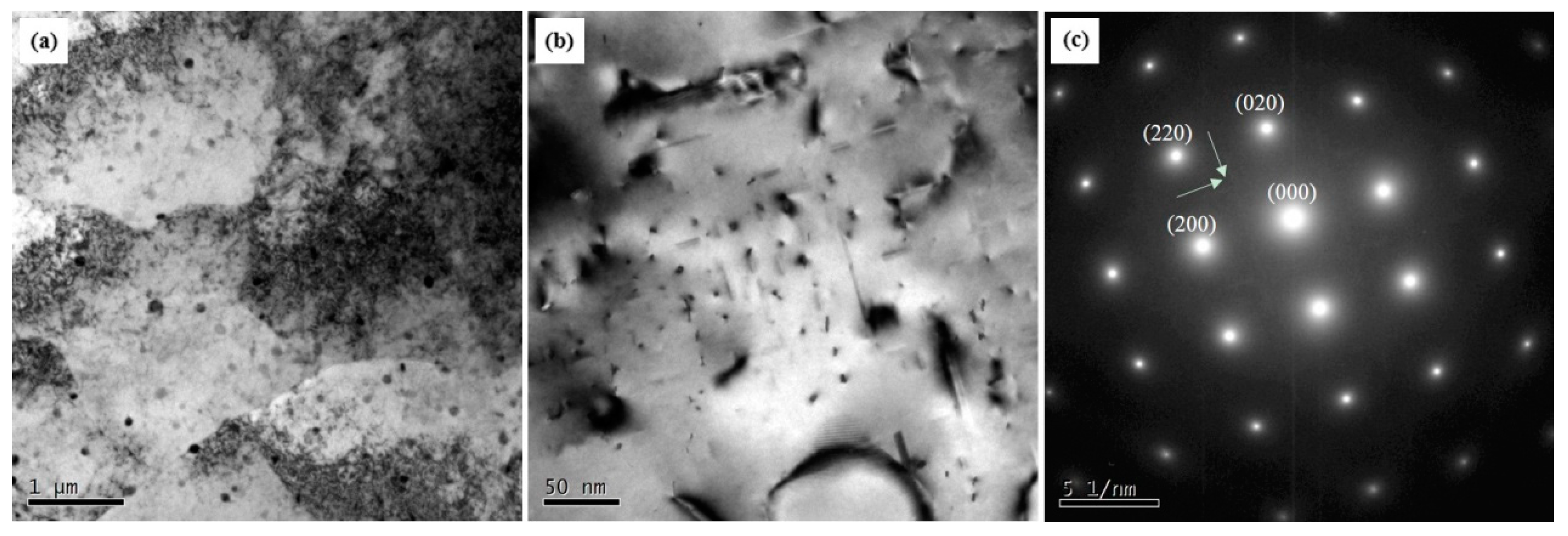
3.1.1. Features in the Single-Sided FSW

Figure 5 shows the grain map and the corresponding grain size distribution, TEM and its diffraction pattern in the single-sided FSW. The average grain size in the NZ was 9.16, 8.49 and 7.38 μm on L1, L2 and L3 line respectively. It is often suggested that the microstructure in the NZ is the result of continuous dynamic recrystallization supported by dynamic recovery [6]. The recrystallized grain size is mainly affected by the heat input in the welding process [6]. More heat input generated in the upper NZ and less heat input in the bottom NZ, which resulted in the larger grain size (9.16 μm) in the upper NZ and smaller grain size (7.38 μm) in the bottom NZ.
In order to study the microstructural evolution, the BM was observed by TEM, as shown in Figure 6. The BM contains a high density of fine hardening precipitates, as reported in the literature [6]. In the 6005A-T6 single-sided FSW, no precipitation was observed in the NZ. It is inferred that precipitations in the NZ were dissolved due to the friction heat and plastic deformation.

3.1.2. Features in the Double-Sided FSW

Figure 7 shows the grain map and the corresponding grain size distribution, TEM and its diffraction pattern in the double-sided FSW. The average grain size in the NZ was 7.48, 6.25 and 9.69 μm on L1, L2 and L3 lines respectively. The grain size in the first pass is much larger than that in the second pass. No precipitation was observed in the NZ of the second-pass region and the middle region. As compared to the BM, fewer precipitations were observed in the NZ of the first-pass region.
The precipitations were dissolved in the second-pass NZ, while the precipitations were observed in the first-pass NZ. As the parameters were the same for the first and second pass, the authors inferred that the precipitations in the NZ were dissolved during the process of dynamic recrystallization in the first weld pass. The heat input by the second weld pass provided the aging temperature that the strengthening phases were precipitated in the first-pass NZ with grain growth occurring at the same time.

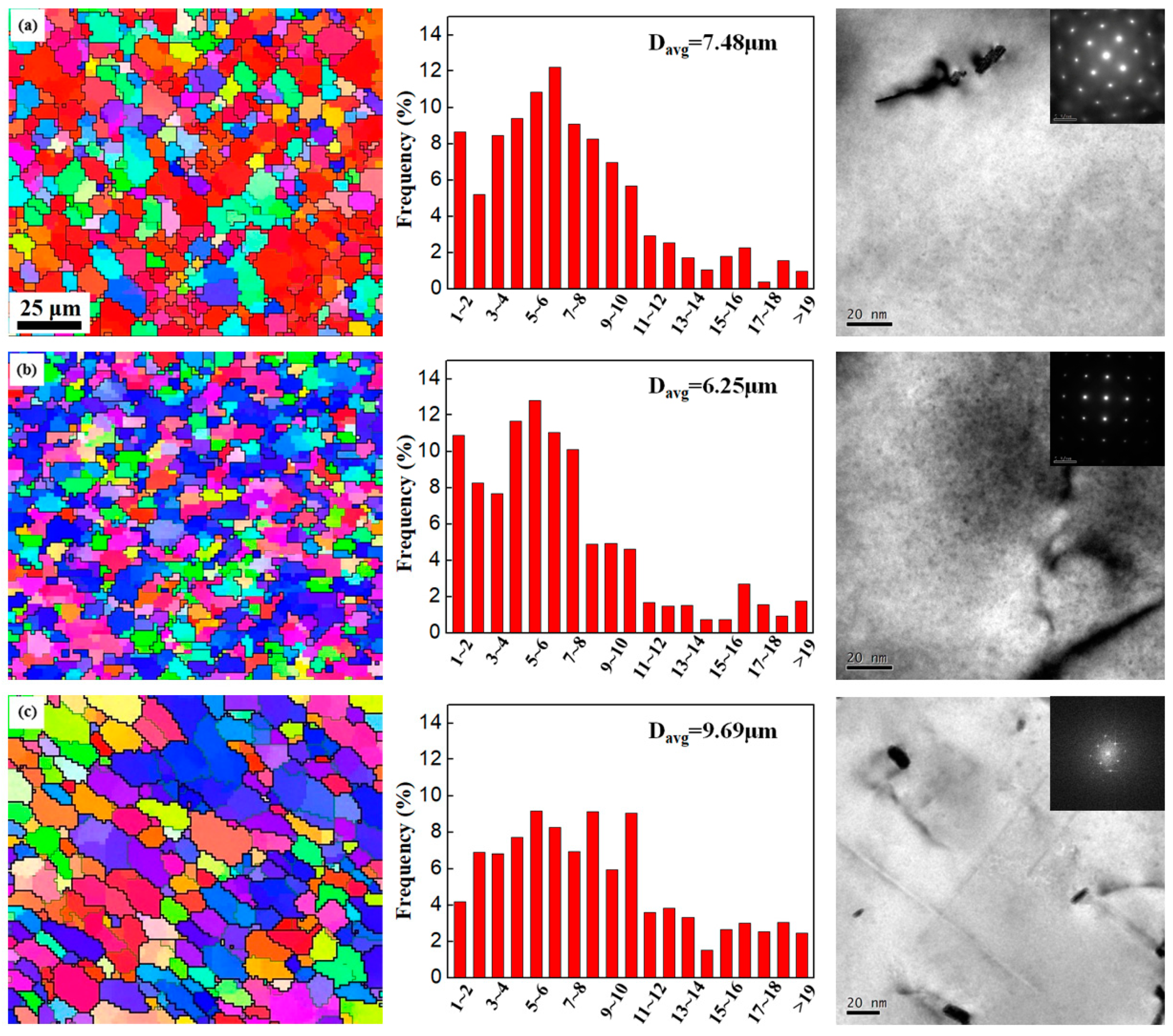
3.1.3. Comparison of Grain Size between Single-Sided and Double-Sided FSWs

The grain size of the NZ in the single-sided FSW is larger than the second pass of the double-sided FSW. The temperature of the NZ in the single-sided FSW is 7.9 °C higher than the double-sided FSW. The higher temperature is useful to activate the dynamic recrystallization and grain growth. This comparison verified the effect of the heat input on the recrystallized grain size.

3.2. Mechanical Properties

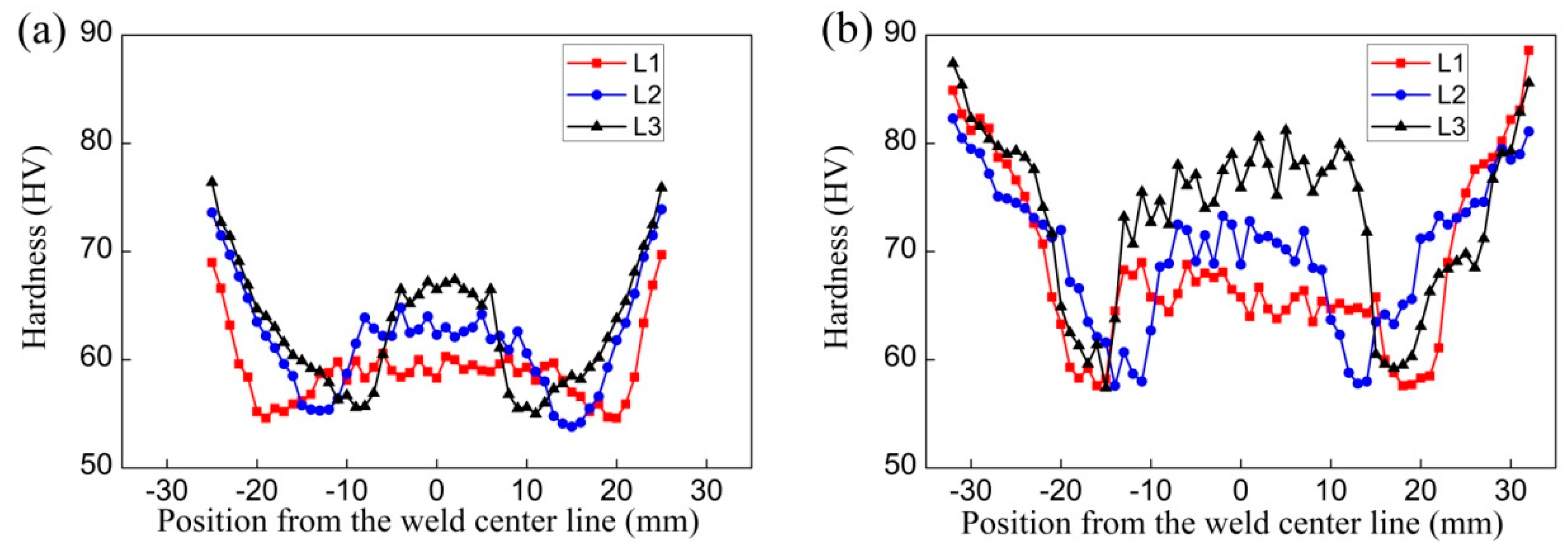
3.2.1. Hardness Distribution

Figure 8 shows the hardness profiles in the weld zone of single-sided and double-sided FSWs. The obtained profiles follow the general features with a central plateau and two valleys, which is a typical hardness behavior for all FSW heat treatable aluminium alloys [6].
In the single-sided FSW, the minimum hardness on three lines is nearly the same with a value of approximately 54 HV and all appear in the HAZ. The valleys on L1 line, L2 line and L3 line are located approximately 20, 15 and 10 mm away from the weld center, respectively. The distance between two valleys decreases towards the bottom of the weld, which corresponds to the shape of the rotating pin. The average hardness of the NZ (central plateau) is 59.2, 62.8 and 66.4 HV on L1, L2, L3 lines, respectively. The hardness in the NZ increases in the order of the upper, middle and bottom regions. With the absence of precipitation in the NZ, fine grains usually benefit the strength [6]. Therefore, the hardness of NZ in the bottom region (grain size 7.38 μm) is 12.2% larger than that in the upper region (grain size 9.16 μm).
In the double-sided FSW, the hardness is generally larger than the single-sided FSW. The minimum hardness on three lines is nearly the same with approximately 58 HV and all appear in the HAZ. The valleys on L1 line, L2 line and L3 line are located approximately 18, 13 and 17 mm away from the weld center, respectively. The average hardness of the NZ (central plateau) is 66.0, 71.1 and 76.9 HV on L1, L2 and L3 lines respectively. The hardness of the middle NZ is 7.7% larger than that of the second-pass NZ. This is caused by the grain size in the middle NZ with 6.25 μm and in the second-pass NZ with 7.48 μm. The hardness of the first-pass NZ is approximately 16.5% larger than the second-pass NZ. The second-pass NZ has no precipitation and smaller grains, while the first-pass NZ has a small quantity of precipitations and larger grains. It is concluded that the strengthening precipitations overwhelm larger grain size in controlling the hardness.

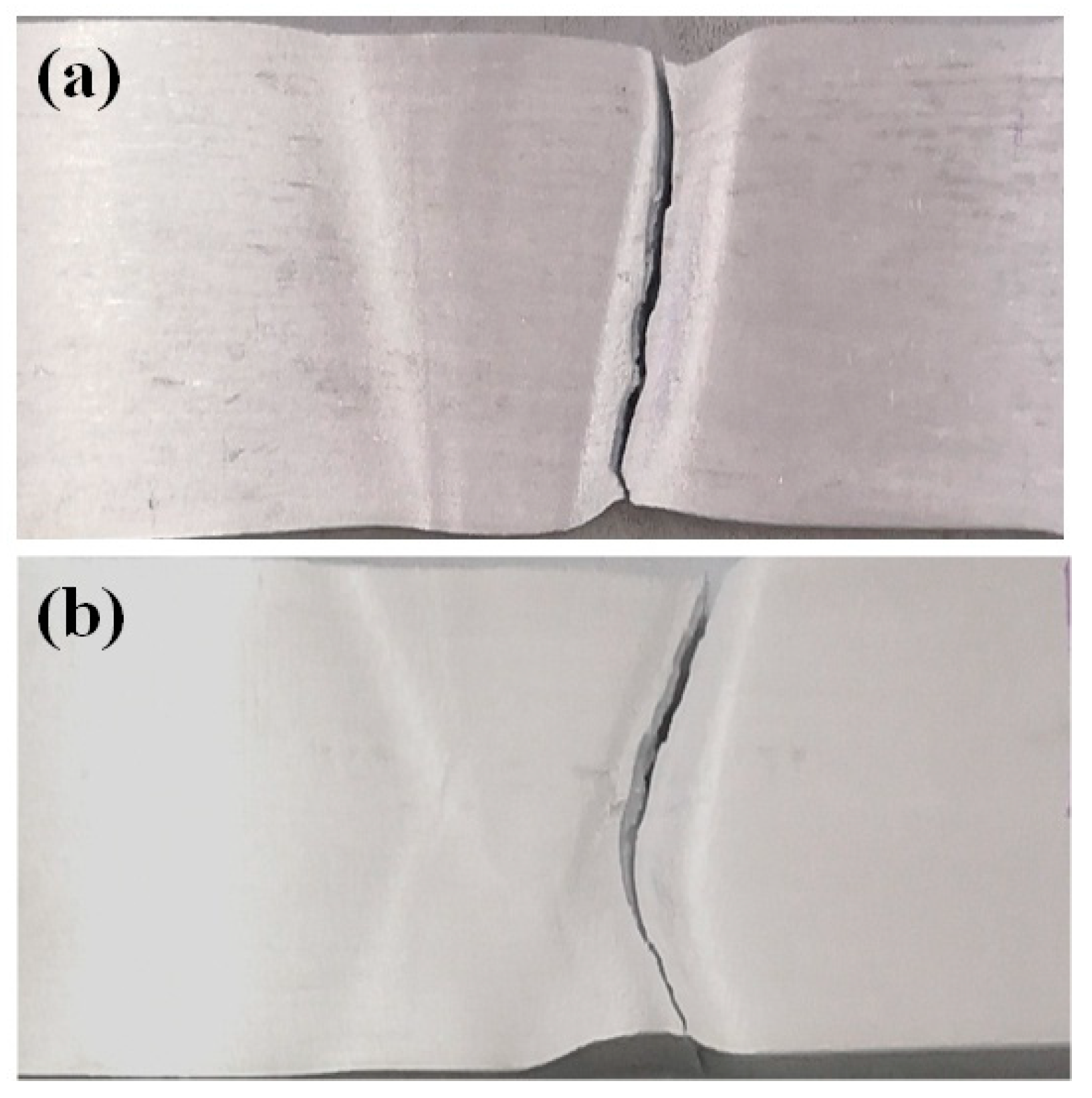
3.2.2. Tensile Strength

The tensile strength of a single-sided FSW and a double-sided FSW was 186 ± 1 MPa and 202 ± 2 MPa, equivalent to 74.4% and 80.8% of BM (250 MPa), respectively. The larger tensile strength coincides with the larger hardness of the double-sided FSW. Figure 9 shows the fracture location of the single-sided FSW and the double-sided FSW. In the single-sided FSW, the fracture occurred in the HAZ of the advancing side. In the double-sided FSW, the crack initiated in the HAZ of the advancing side of the second pass and propagated to the HAZ of the retreating side of the first pass.

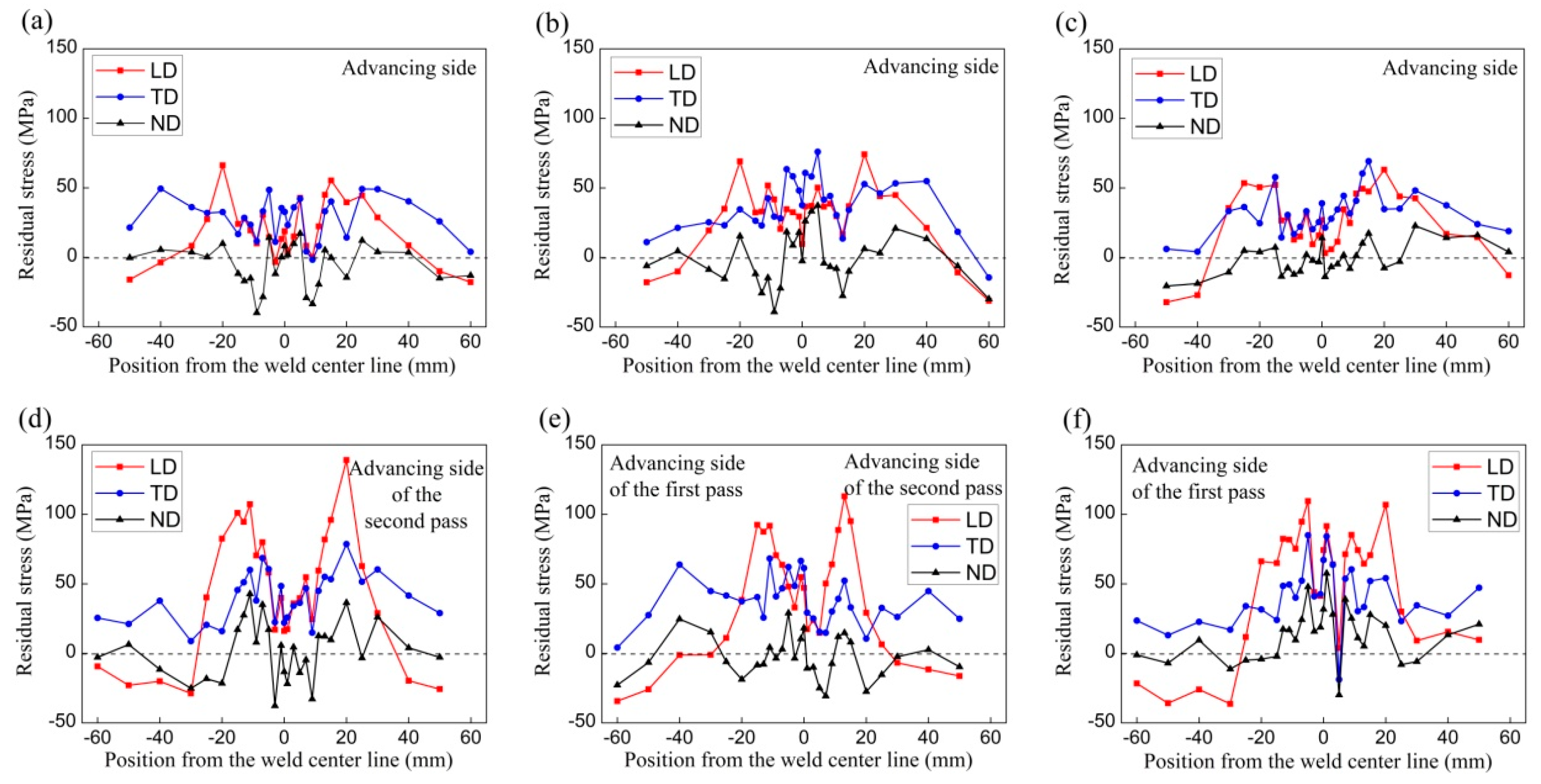
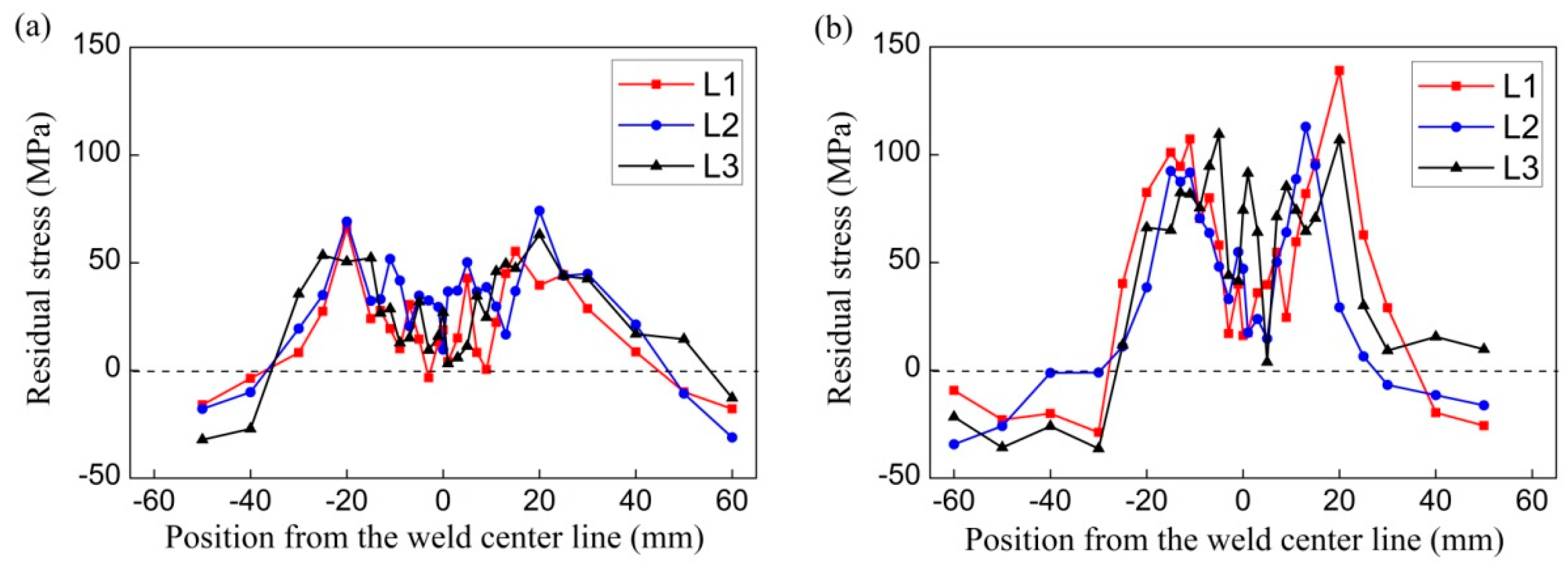
3.3. Residual Stresses

Figure 10 shows the residual stresses determined by neutron diffraction in the 6005A-T6 aluminium alloy single-sided and double-sided FSWs. In both specimens, the longitudinal and transverse residual stress distributions agreed with the typical ‘M’ shape pattern of FSW aluminum alloys [6]. The normal residual stresses were observed with little variations, especially on L3 line of the single-sided FSW which remained near to a value of zero. Notably, the average uncertainty of the obtained stresses is approximately ±13 MPa in these measurements.

3.3.1. Features in the Single-Sided FSW

In the single-sided FSW, the residual stresses along the three lines have a similar distribution in both trend as well as magnitude. σLD is generally equal to σTD and larger than σND. The maximum tensile σLD and σTD are nearly the same, approximately 75 MPa. This stress value amounts to 37.5% of the yield strength of Al-6005A-T6 alloy, which is 200 MPa at room temperature.
The introduction of residual stresses is inevitable due to severe thermomechanical deformation by FSW. Therefore, it is important to control the amount of residual stress. Hassan et al. reported an optimum combination of rotational and travel speeds that gave the best mechanical performance [11]. This optimum condition shifted to a higher rotational speed when the travel speed was increased. High heat input associated with low traverse and high rotation speeds leads to more extensive softening in the weld region, resulting in an overall reduction in the magnitude of the longitudinal residual stress. It seems difficult to get both optimized mechanical properties and residual stresses. However, the present 6005A-T6 single-sided FSW achieved an acceptable condition for comprising the mechanical properties with a tensile strength of 74.4% of BM and residual stresses with peak magnitudes of approximately 37.5% yield strength of BM.

3.3.2. Features in the Double-Sided FSW

In the double-sided FSW, σLD is generally larger than σND and σTD. There is large difference between σLD magnitudes on the three lines, as shown in Figure 11. The maximum tensile σLD is approximately 140 MPa on L1 line (xt = −10), 115 MPa on L2 line (xt = 0) and 110 MPa on L3 line (xt = 10) respectively. These stress values amount to 70%, 57.5% and 55% of the yield strength of BM. The residual stress profiles of the L1 line and L2 line show obvious asymmetric distributions. The highest stresses of those lines occur on the advancing side of the NZ compared to the retreating side. The maximum residual stress in the upper weld zone is 140 MPa, 27% larger than the bottom weld zone, where the stress is 110 MPa. As the parameters were the same for the first and second pass, an inference was made that the peak magnitude of residual stress produced by the first weld pass was approximately 140 MPa. The heat input by the second weld pass provided the post-treatment environment of stress relaxation for the first-pass weld zone.
Although the tensile strength of the double-sided FSW was a little higher than the single-side FSW, the longitudinal residual stresses in the double-sided FSW are much larger than the single-sided FSW, as shown in Figure 11.

4. Summary and Conclusions

In this study, residual stresses, microstructures and mechanical properties of the 6005A-T6 single-sided and double-sided FSWs were studied. The 3D residual stresses were characterized using neutron diffraction. The microstructures were observed by TEM and EBSD.
In the 6005A-T6 single-sided FSW, there were acceptable mechanical properties with tensile strength 74.4% of BM, and low residual stresses with peak magnitudes of approximately 37.5% yield strength of BM were achieved. This indicated a good quality of weld with such low residual stresses. However, good mechanical properties with a tensile strength of 80.8% of BM, but high residual stresses with peak magnitudes of approximately 70% yield strength of BM were obtained in the 6005A-T6 double-sided FSW.
In the 6005A-T6 single-sided FSW, there was no precipitation in the NZ. The hardness of the NZ is related to the grain size. The less hardness at the upper NZ and high hardness at the bottom NZ coincided with the larger grain size at the upper NZ and smaller grain size at the bottom NZ, respectively.
In the 6005A-T6 double-sided FSW, there were lower residual stresses and larger hardness in the first-pass weld zone, but higher residual stresses and smaller hardness in the second-pass weld zone. This was due to the heat input by the second weld pass which provided an aging environment for the first-pass weld zone, where the dissolved phases were precipitated and residual stresses were relaxed.

Author Contributions

Conceptualization, X.L. and H.Z.; investigation, P.X., R.W., R.L. and M.L.; Writing—Original Draft preparation, X.L.; Writing—Review and Editing, W.L., Y.L. and D.C.; funding acquisition, Y.L. and D.C.

Funding

This research activity was financially supported by Ministry of Science and Technology of China (grant 2017YFA0403704), National Natural Science Foundation of China (grants 11605293 and 51327902).

Conflicts of Interest

The authors declare no conflict of interest.

References

  1. Simar, A.; Bréchet, Y.; De Meester, B.; Denquin, A.; Pardoen, T. Microstructure, local and global mechanical properties of friction stir welds in aluminium alloy 6005A-T6. Mater. Sci. Eng. A 2008, 486, 85–95. [Google Scholar] [CrossRef]
  2. Ji, S.; Meng, X.; Liu, J.; Zhang, L.; Gao, S. Formation and mechanical properties of stationary shoulder friction stir welded 6005A-T6 aluminum alloy. Mater. Des. 2014, 62, 113–117. [Google Scholar] [CrossRef]
  3. Lee, W.B.; Yeon, Y.M.; Jung, S.B. Evaluation of the microstructure and mechanical properties of friction stir welded 6005 aluminum alloy. Mater. Sci. Technol. 2003, 19, 1513–1518. [Google Scholar] [CrossRef]
  4. Peng, D.; Hongmei, L.; Daqian, S.; Wenbiao, G.; Jie, L. Effects of welding speed on the microstructure and hardness in friction stir welding joints of 6005A-T6 aluminium alloy. Mater. Des. 2013, 45, 524–531. [Google Scholar]
  5. Thomas, W.M.; Nicholas, E.D.; Needham, J.C.; Murch, M.G.; Temple-Smith, P.; Dawes, C.J. The Welding Institute, TWI. International Patent Application No. PCT/GB92/02203; GB Patent Application No. 9125978.8, 6 December 1991. [Google Scholar]
  6. Threadgill, P.L.; Leonard, A.J.; Shercliff, H.R.; Withers, P.J. Friction stir welding of aluminium alloys. Int. Mater. Rev. 2009, 54, 49–93. [Google Scholar] [CrossRef]
  7. Xu, W.; Liu, J.; Zhu, H. Analysis of residual stresses in thick aluminum friction welded butt joints. Mater. Des. 2011, 32, 2000–2005. [Google Scholar] [CrossRef]
  8. Wang, X.L.; Feng, Z.; David, S.A.; Spooner, S.; Hubbard, C.R. Neutron diffraction study of residual stresses in friction stir welds. In Proceedings of the 6th International Conference on Residual stresses, Oxford, UK, 10–12 July 2000; pp. 1408–1414. [Google Scholar]
  9. Haghshenas, M.; Gharghouri, M.A.; Bhakhri, V.; Klassen, R.J.; Gerlich, A.P. Assessing residual stresses in friction stir welding: Neutron diffraction and nanoindentation methods. Int. J. Adv. Manuf. Technol. 2017, 93, 3733–3747. [Google Scholar] [CrossRef]
  10. Mehra, S.; Dhanda, P.; Khanna, R.; Goyat, N.S.; Verma, S. Effect of tool on tensile strength in single and double sided friction stir welding. Int. J. Sci. Eng. Res. 2012, 3, 1–6. [Google Scholar]
  11. Hassan, K.A.; Prangnell, P.B.; Norman, A.F.; Price, D.A.; Williams, S.W. Effect of welding parameters on nugget zone microstructure and properties in high strength aluminium alloy friction stir welds. Sci. Technol. Weld. Join. 2003, 8, 257–268. [Google Scholar] [CrossRef]
  12. Meng, X.; Gao, S.; Ma, L.; Li, Z.; Yue, Y.; Xiao, H. Effects of rotational velocity on microstructures and mechanical properties of surface compensation friction stir welded 6005A-T6 aluminum alloy. Eng. Rev. 2016, 36, 107–113. [Google Scholar]
  13. Sakala, R.S.; Renangi, S.; Indira, R.M. Experimental study of double sided friction stir welding of AA 6061 plates using hexagonal tool tip. Int. J. Res. Advent Technol. 2018, 6, 32–37. [Google Scholar]
  14. Asgar, K.; Abdul, S.M.K.; Bharat, K. Fabrication of a butt joint using friction stir welding (FSW)—A non consumable tool to generate heat. Int. J. Res. Sci.Innov. 2016, 3, 53–55. [Google Scholar]
  15. Woo, W.; Feng, Z.; Wang, X.L.; Brown, D.W.; Clausen, B.; An, K.; Choo, H.; Hubbard, C.R.; David, S.A. In situ neutron diffraction measurements of temperature and stresses during friction stir welding of 6061-T6 aluminium alloy. Sci. Technol. Weld. Join. 2007, 12, 298–303. [Google Scholar] [CrossRef]
  16. Simar, A.; Bréchet, Y.; De Meester, B.; Denquin, A.; Gallais, C.; Pardoen, T. Integrated modeling of friction stir welding of 6xxx series Al alloys: Process, microstructure and properties. Prog. Mater. Sci. 2012, 57, 95–183. [Google Scholar] [CrossRef] [Green Version]
  17. Liu, H.; Yang, S.; Xie, C.; Zhang, Q.; Cao, Y. Microstructure characterization and mechanism of fatigue crack initiation near pores for 6005A CMT welded joint. Mater. Sci. Eng. A 2017, 707, 22–29. [Google Scholar] [CrossRef]
  18. Dong, P.; Sun, D.; Wang, B.; Zhang, Y.; Li, H. Microstructure, microhardness and corrosion susceptibility of friction stir welded AlMgSiCu alloy. Mater. Des. 2013, 54, 760–765. [Google Scholar] [CrossRef]
  19. Feng, Z.; Wang, X.L.; David, S.A.; Sklad, P.S. Modeling of residual stresses and property distributions in friction stir welds of aluminum alloy 6061-T6. Sci. Technol. Weld. Join. 2013, 12, 348–356. [Google Scholar] [CrossRef]
  20. Woo, W.; Feng, Z.; Wang, X.L.; David, S. Neutron diffraction measurements of residual stresses in friction stir welding: A review. Sci. Technol. Weld. Join. 2011, 16, 23–32. [Google Scholar] [CrossRef]
  21. Malopheyev, S.; Vysotskiy, I.; Kulitskiy, V.; Mironov, S.; Kaibyshev, R. Optimization of processing-microstructure-properties relationship in friction-stir welded 6061-T6 aluminum alloy. Mater. Sci. Eng. A 2016, 662, 136–143. [Google Scholar] [CrossRef]
  22. Deplus, K.; Simar, A.; Van Haver, W.; De Meester, B. Residual stresses in aluminium alloy friction stir welds. Int. J. Adv. Manuf. Technol. 2011, 56, 493–504. [Google Scholar] [CrossRef]
  23. Simar, A.; Bréchet, Y.; De Meester, B.; Denquin, A.; Pardoen, T. Sequential modeling of local precipitation, strength and strain hardening in friction stir welds of an aluminum alloy 6005A-T6. Acta Mater. 2007, 55, 6133–6143. [Google Scholar] [CrossRef] [Green Version]
  24. Tao, W.; Yong, Z.; Xuemei, L.; Matsuda, K. Special grain boundaries in the nugget zone of friction stir welded AA6061-T6 under various welding parameters. Mater. Sci. Eng. A 2016, 671, 7–16. [Google Scholar] [CrossRef]
  25. Węglowski, M.S.; Sędek, P.; Hamilton, C. The effect of process parameters on residual stress in a Friction stir processed cast aluminium alloy. Eng. Trans. 2016, 64, 301–309. [Google Scholar]
  26. Prime, M.; Gnaupel-Herold, T.; Baumann, J.; Lederich, R.; Bowden, D.; Sebring, R. Residual stress measurements in a thick, dissimilar aluminum alloy friction stir weld. Acta Mater. 2006, 54, 4013–4021. [Google Scholar] [CrossRef]
  27. Sepe, R.; Armentani, E.; Di Lascio, P.; Citarella, R. Crack Growth Behavior of Welded Stiffened Panel. Procedia Eng. 2015, 109, 473–483. [Google Scholar] [CrossRef] [Green Version]
  28. Citarella, R.; Carlone, P.; Lepore, M.A.; Sepe, R. Hybrid technique to assess the fatigue performance of multiple cracked FSW joints. Eng. Fract. Mech. 2016, 162, 38–50. [Google Scholar] [CrossRef]
  29. Citarella, R.; Carlone, P.; Sepe, R.; Lepore, M.A. DBEM crack propagation in friction stir welded aluminum joints. Adv. Eng. Softw. 2016, 101, 50–59. [Google Scholar] [CrossRef]
  30. Patel, V.; Li, W.; Wang, G.; Wang, F.; Vairis, A.; Niu, P. Friction Stir Welding of Dissimilar Aluminum Alloy Combinations: State-of-the-Art. Metals 2019, 9, 270. [Google Scholar] [CrossRef]
  31. Sonne, M.R.; Carlone, P.; Hattel, J.H. Assessment of the Contour Method for 2-D Cross Sectional Residual Stress Measurements of Friction Stir Welded Parts of AA2024-T3—Numerical and Experimental Comparison. Metals 2017, 7, 508. [Google Scholar] [CrossRef]
  32. Fadaeifard, F.; Matori, K.A.; Aziz, S.A.; Zolkarnain, L.; Rahim, M.A.Z.B.A.; Rahim, M.A. Effect of the Welding Speed on the Macrostructure, Microstructure and Mechanical Properties of AA6061-T6 Friction Stir Butt Welds. Metals 2017, 7, 48. [Google Scholar] [CrossRef]
  33. Li, S.; Chen, Y.; Kang, J.; Amirkhiz, B.S.; Nadeau, F. Effect of Revolutionary Pitch on Interface Microstructure and Mechanical Behavior of Friction Stir Lap Welds of AA6082-T6 to Galvanized DP800. Metals 2018, 8, 925. [Google Scholar] [CrossRef]
  34. Niu, P.; Li, W.; Zhang, Z.; Yang, X. Global and local constitutive behaviors of friction stir welded AA2024 joints. J. Mater. Sci. Technol. 2017, 33, 987–990. [Google Scholar] [CrossRef]
  35. Hutchings, M.T.; Withers, P.J.; Holden, T.M.; Lorentzen, T. Introduction to the Characterization of Residual Stress by Neutron Diffraction, 1st ed.; Taylor and Francis: London, UK, 2005. [Google Scholar]
  36. Liu, X.; Wimpory, R.C.; Gong, H.; Liu, Y.; Chen, D.; Liu, Y.; Wu, Y.; Li, C. The Determination of Residual Stress in Quenched and Cold-Compressed 7050 Aluminum Alloy T-Section Forgings by the Contour Method and Neutron Diffraction. J. Mater. Eng. Perform. 2018, 27, 6049–6057. [Google Scholar] [CrossRef]
  37. Wimpory, R.; Mikula, P.; Šaroun, J.; Poeste, T.; Li, J.; Hofmann, M.; Schneider, R. Efficiency Boost of the Materials Science Diffractometer E3 at BENSC: One Order of Magnitude Due to a Horizontally and Vertically Focusing Monochromator. Neutron News 2008, 19, 16–19. [Google Scholar] [CrossRef]
  38. Mishra, R.; Ma, Z.; Mishra, R. Friction stir welding and processing. Mater. Sci. Eng. R Rep. 2005, 50, 1–78. [Google Scholar] [CrossRef]
  39. Qian, J.W.; Li, J.L.; Xiong, J.T.; Zhang, F.S.; Li, W.Y.; Lin, X. Periodic variation of the torque and its relations to interfacial sticking and slipping during friction stir welding. Sci. Technol. Weld. Join. 2012, 17, 338–341. [Google Scholar] [CrossRef]
  40. Randau, C.; Garbe, U.; Brokmeier, H.G. StressTextureCalculator: A software tool to extract texture, strain and microstructure information from area-detector measurements. J. Appl. Crystallogr. 2011, 44, 641–646. [Google Scholar] [CrossRef]
  41. Gnäupel-Herold, T. ISODEC: Software for calculating diffraction elastic constants. J. Appl. Crystallogr. 2012, 45, 573–574. [Google Scholar] [CrossRef]
Figure 1. The layout of single-sided and double-sided friction stir welding (FSWs).
Metals 09 00803 g001
Figure 2. The experimental setup.
Metals 09 00803 g002
Figure 3. The layout of a tensile specimen.
Metals 09 00803 g003
Figure 4. Macrographs (optical) of a single-sided FSW (a) and a double-sided FSW (b).
Metals 09 00803 g004
Figure 5. The grain map (on the left), grain size distribution (in the middle), TEM and diffraction pattern (on the right) of the NZ on L1 (a), NZ on L2 (b) and NZ on L3 (c) in the single-sided FSW.
Metals 09 00803 g005
Figure 6. The microstructure of the base metal (BM) observed by SEM (a), TEM (b) and the diffraction pattern (c).
Metals 09 00803 g006
Figure 7. The grain map (on the left), grain size distribution (in the middle), TEM and diffraction pattern (on the right) of the NZ on L1 (a), NZ on L2 (b) and NZ on L3 (c) in the double-sided FSW.
Metals 09 00803 g007
Figure 8. The hardness distribution in the single-sided FSW (a) and the double-sided FSW (b).
Metals 09 00803 g008
Figure 9. The fracture location of the single-sided FSW (a) and the double-sided FSW (b).
Metals 09 00803 g009
Figure 10. Residual stresses on L1 (a), L2 (b), L3 (c) in the single-sided FSW and L1 (d), L2 (e), L3 (f) in the double-sided FSW.
Metals 09 00803 g010
Figure 11. Replot of longitudinal residual stresses in a single-sided FSW (a) and a double-sided FSW(b).
Metals 09 00803 g011
Table 1. The chemical composition and mechanical properties of 6005A aluminium alloy.
Chemical Composition (wt.%)Mechanical Properties
MgSiFeCuMnCrTiZnAlYielding Strength (MPa)Tensile Strength (MPa)
0.540.620.190.070.140.010.010.02Bal.250200

