Article

Interface Behavior and Impact Properties of Dissimilar Al/Steel Keyhole-Free FSSW Joints

1
School of Materials Science and Engineering, Lanzhou University of Technology, Lanzhou 730050, China
2
School of Materials Science and Engineering, Tongji University, Shanghai 201804, China
3
Aeronautical Key Laboratory for Welding and Joining Technologies, AVIC Manufacturing Technology Institute AECC, Beijing 100024, China
*
Author to whom correspondence should be addressed.
Metals 2019, 9(6), 691; https://doi.org/10.3390/met9060691
Submission received: 28 April 2019 / Revised: 11 June 2019 / Accepted: 13 June 2019 / Published: 18 June 2019
(This article belongs to the Special Issue Characterization of Welded Joints)

Abstract

:
This work systematically investigates the interface behavior and impact properties of the keyhole-free friction stir spot welding (FSSW) of a dissimilar metal AA6082-T4 Al alloy and DP600 galvanized steel. The keyhole is eliminated by pin retraction technology. The welding process is in accordance with the welding temperature curve and the maximum temperature of the periphery of the shoulder, measured at about 500 °C. The transition layers were formed at the interface, in which the Al, Fe, and Zn elements form an inhomogeneous diffusion. A cloud cluster-like mechanical mixing of the Al and steel components is formed in the stirring zone. The impact toughness of the specimen with a welding parameter of 1000 rpm is the best. To a certain extent, the factors affecting the impact energy are not the maximum impact load but the maximum impact deformation. The maximum impact deformation directly reflects the post-crack propagation energy, which significantly affects its impact toughness. In addition, the impact fracture showed a mixed ductile and brittle fracture mode with a brittle–ductile transition zone. Most of the impact energy was absorbed by the ductile fracture.

Graphical Abstract

1. Introduction

Friction stir spot welding (FSSW) is a type of solid-state welding process that combines friction stir welding (FSW) and spot welding. FSSW is widely used for the connection of similar Al alloys [1] and Mg alloys [2] and dissimilar Al/steel [3], Al/Cu [4], Al/Mg [5] and Mg/steel [6] materials in the transportation and aerospace industries. In order to realize lightweight automobiles, Al and Mg alloys are widely used as substitutes for steel, which can effectively reduce the overall weight of the automobile body, and achieve energy conservation and environmental protection. However, the melting points of Al and steel are quite different, which makes them difficult to weld.
Compared with solid state welding, it is easier to produce gas pockets and intermetallic compounds (IMCs) in dissimilar Al/steel joints during fusion welding, which results in a decline in the mechanical properties of joints. Similarly, there are some inevitable defects in FSW and FSSW, such as keyholes [7], hook defects [8,9,10], and IMCs [11,12,13]. These defects seriously affect the forming quality, tensile-shear strength, impact toughness, and fatigue life of welded joints. Therefore, a deeper understanding of dissimilar Al/steel FSSW is necessary. In order to overcome the above welding defects, keyhole-free FSSW techniques have been developed based on traditional FSSW technology. The remaining keyhole is the weakest area of the weld, and the joint first form cracks at the edge of the keyhole. Kubit et al. [7] found that keyholes and alclads are the main weld defects that worsen the joint quality in the FSSW process. Refilled friction stir spot welding (RFSSW) can fill the keyhole to avoid structural defects. In addition, FSSW joints can be divided into four zones: the weld nugget zone (WNZ), thermo-mechanically affected zone (TMAZ), heat-affected zone (HAZ), and base metal (BM). Reimann et al. [14] found partial recrystallization in the stir zone for the first time using the stop-action technique. Chen [10] and Cao [15] et al. observed fine grains and shear texture in the stir zone and proved that the microstructure’s evolution was related to recrystallization in the RFSSW of the 6061-T6 alloy.
The hook defect is formed by the plunge of the tool pin, causing a large extrusion deformation of the material during FSW. Garg and Bhattacharya [9] found that hook formation is related to the length of the tool pin. A pinless tool can obscure hook formation and improve joint strength. Chen et al. [10] investigated the microstructure and mechanical properties of the RFSSW of a 6061 Al alloy to transformation-induced plasticity (TRIP) steel. They proved that RFSSW increases the joint’s strength by 56.33% compared with that of conventional FSSW joints. In contrast, they thought that the hook structure generated in the regular FSSW step is indispensable for a strong joint.
IMCs, as brittle phases, are also one of the main causes of joint cracking. Hsieh et al. [11] obtained dissimilar lap joints for a low carbon steel (SS400) sheet on a 6061-T6 Al alloy sheet, which were achieved by FSSW with a welding tool that had an independent tool pin and shoulder. They found that two IMC layers, Fe2Al5 and Fe4Al13, were formed at this surface, and the failure load was related to the thickness of the IMC layer. Bozzi et al. [12] also studied the IMCs of joints of 6016 Al alloy to IF-steel performed by FSSW and reached the same conclusion. They noted, at the same time, that the presence of IMCs depends on the welding conditions. Dong et al. [13] studied dissimilar lap joints of a Novelist AC 170 PX Al alloy and 1.2 mm thick ST06 Z galvanized steel sheets with RFSSW. They found that the IMC layer of ZnO, which was as thin as 0.68 μm in the sleeve-plunging zone, was the weakest part of the structure. Although the diameter of the welded spot was 9 mm, the maximum tensile/shear fracture load was only 4.5 kN. They also predicted the material flow during the Refilled FSSW/sleeve plunging process by the distribution of stirred zinc coating.
A large number of numerical simulation analyses of FSSW have been carried out. The temperature field, the stress and strain fields, the welding force, the residual stress, the formability, the material flow, and grain size of welding have become the focus of numerical simulations of FSSW [16,17,18,19,20,21,22,23,24]. At the same time, many articles have reported the shear-tensile strength and fatigue properties of FSSW joints [25,26,27,28]. However, there are few publications that study the impact properties of spot-welding structures, especially keyhole-free FSSW joints. Several studies on impact toughness mainly focused on the friction stir butt-welded joints of thick plates [29,30,31]. In this work, the microstructure and interface behavior of dissimilar Al/steel keyhole-free FSSW joints are studied and analyzed in combination with the keyhole-free FSSW process. In order to determine the relationship between the microstructure and the mechanical properties of the keyhole-free FSSW joints, an impact test was carried out on the dissimilar Al/steel keyhole-free FSSW joint.

2. Experimental Procedures

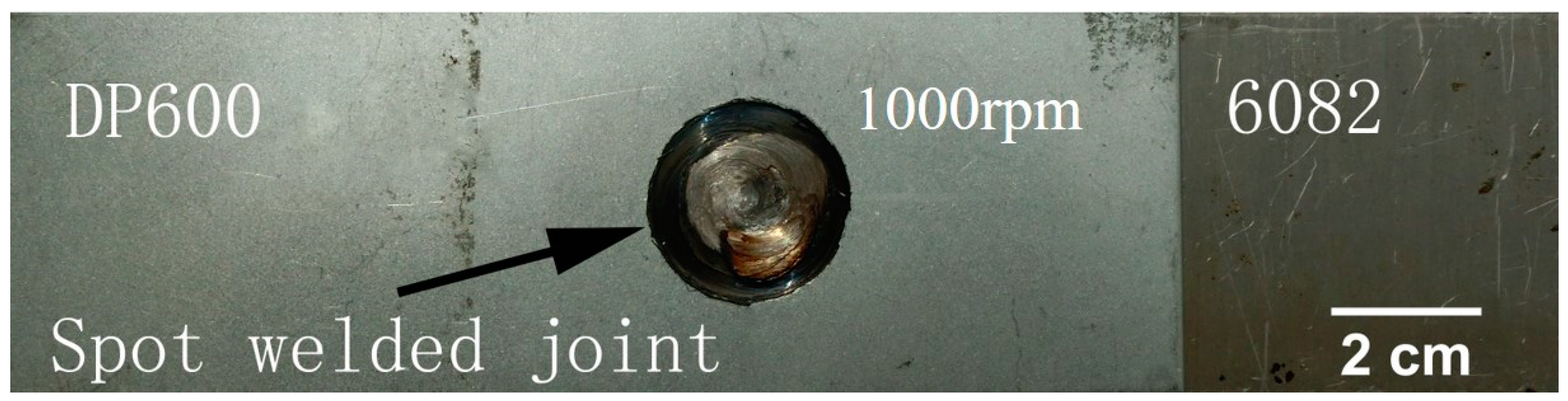
2.1. Materials and Fabrication Process

AA6082-T4 Al alloy plates and DP600 galvanized steel plates were used in the experiment. Their dimensions were 150 mm × 50 mm × 2 mm and 150 mm × 50 mm × 1 mm, respectively. Table 1 and Table 2 show the chemical composition of the 6082 Al alloy and DP600 galvanized steel.
The joints of the dissimilar 6082 Al alloy and the DP600 galvanized steel were welded by a retractile keyhole-free FSSW machine. The welding tool was made of a nickel-based super alloy with a tool shoulder of 20 mm in diameter and a tool pin of 5 mm in diameter and 2.1 mm in length. The pin can move up and down and rotate freely in the inner hole of the shoulder [32]. The spot-welded joints adopt the overlap form of positioning the steel plate on Al plate. This is different from another form of Al plate on the top of the joint [33], although in terms of the cost of the welding tool, it can improve the life of the welding tool. The overlapping form of steel on top can make the tool pin penetrate the steel plate and mix the steel plate and the aluminum plate thoroughly. At the same time, it increases the welding temperature and the thermoplastic deformation of the steel side, which can improve the quality of the dissimilar Al/steel spot-welding joint. The welding process of the dissimilar Al/steel retractile keyhole-free FSSW is shown in Figure 1. In the welding process, the pin and shoulder rotated simultaneously, and the rotational speeds of the welding tool ωr were 800 rpm, 1000 rpm, and 1200 rpm, respectively. When the rotational speed of the welding tool reaches a steady state, it begins to plunge, and the plunge speed vp was 5 mm/min (in Figure 1a). The shoulder plunge depth ds was 0.3 mm after the tool shoulder reached the surface of the workpiece (in Figure 1b) [33,34]. Then, the welding tool was moved forward at a speed vf of 3 mm/min, and the tool pin moved upward at a speed vu of 5 mm/min (in Figure 1c). When the pin was lifted by 2.1 mm relative to the shoulder, the bottom of the pin was level with the bottom of the shoulder. At that point, the pin stopped moving upward, and the shoulder stopped moving forward. This is equivalent to the tool pin moving forward approximately 1.5 mm. With the stirring, retracting, and advancing of the stirring pin, the thermoplastic metal near the stirring pin could gradually fill the rear keyhole under the action of the shoulder. Then, the welding tool moved upward (in Figure 1d). When the welding tool was moved to a safe distance, the tool shoulder and tool pin simultaneously reset and the keyhole-free FSSW joint was obtained (in Figure 1e). At the same time, the thermocouples are used to measure the temperature of dissimilar Al/steel joints during keyhole-free FSSW. Figure 2 shows the schematic diagram of thermocouple distribution around the dissimilar Al/steel joint during keyhole-free FSSW. The welded structure adopts the overlap form, and the rotating direction is shown in Figure 2. Four thermocouples are evenly placed around the spot-welded joints on the steel plate, and the welding temperature is measured in real time through the four channels.

2.2. Microstructure Characterization
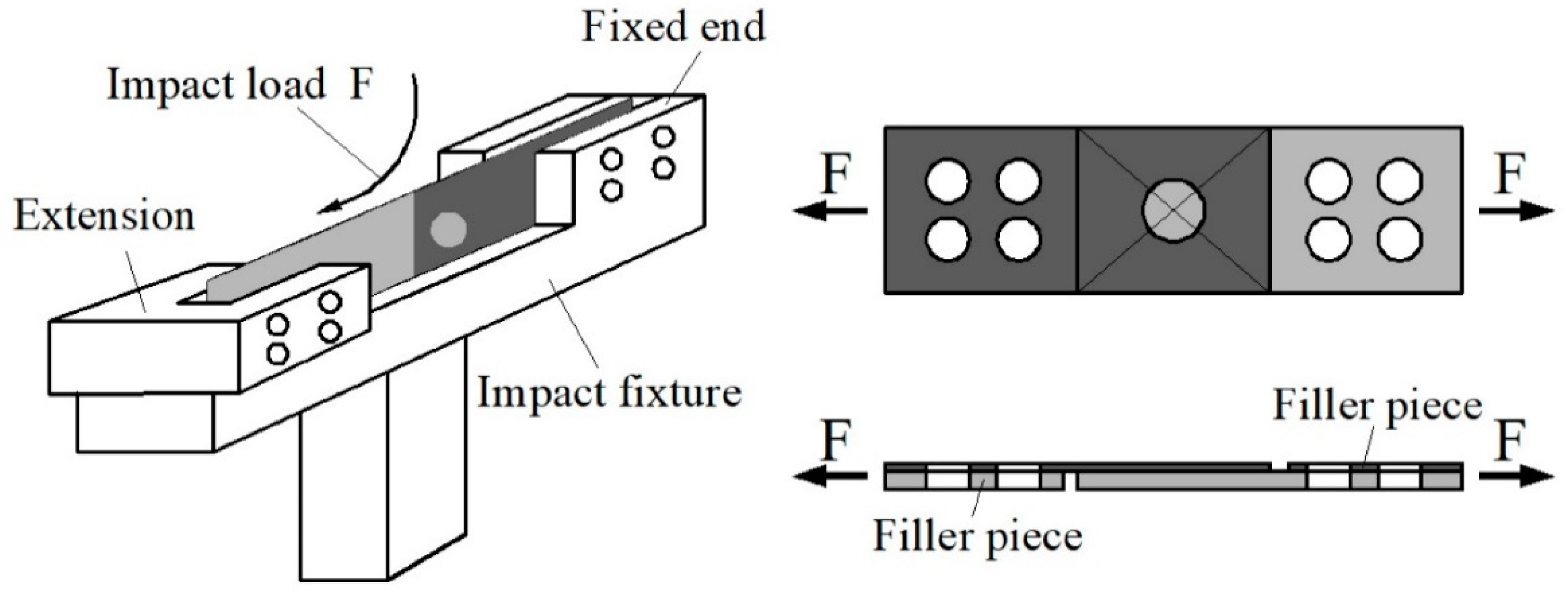
The cross-sectional specimens of the keyhole-free FSSW joints, with dimensions of 40 mm × 3 mm × 15 mm, were cut off by wire cutting. They were used for microscopic metallographic and interface analyses. The cross-sectional specimens were ground with sandpaper, polished with a polishing cloth, and then cleaned with anhydrous alcohol. The Al layer of the cross-sectional specimens was etched with Keller’s etchant (2.5 mL HNO3, 1.5 mL HCl, 1.0 mL HF, and 95 mL distilled water) for 20 s, and the steel layer was etched with a 4% nitric acid alcohol etchant for 4 s.
The microstructure of the keyhole-free FSSW joint was observed using an MeF3 large metallographic microscope (Leica Corporation, Wetzlar, Germany). The interfacial behavior, metal fluidity, and impact fracture of the keyhole-free FSSW joints were studied on a JSM-5600LV low-vacuum scanning electron microscope (SEM) (Japan Electron Optics Laboratory Company, Tokyo, Japan), and the interface element diffusion was measured with an X-ray energy-dispersive spectrometer (EDS) (Oxford Instruments, Oxford, UK). The IMCs of the keyhole-free FSSW joint were analyzed by X-ray diffractometry (XRD) (BRUKER-AXS Corporation, Billerica, Mass, Germany).

2.3. Impact Tests

The cantilever method was used to carry out impact experiments on the dissimilar Al/steel keyhole-free FSSW joints with different welding parameters. There were three specimens in each group of experiments. The cantilever impact test was performed on a CIEM-30D-CPC modified oscillographic impact testing machine (Tokyo Testing Machine MFG. CO. LTD, Tokyo, Japan). Figure 3 shows the cantilever impact schematic of the dissimilar Al/steel keyhole-free FSSW joints. One end of the sample was fixed on the impact fixture, and the other end was connected to an extension body with a long screw and nut, as shown in Figure 3. The extension body is separated from the impact fixture and can move freely. Aluminum and steel filler pieces of the same thickness and material are installed on both sides of the sample to keep the direction of force unchanged. The falling pendulum hammer hit the extension body horizontally, resulting in the fracture of the keyhole-free FSSW joint. The impact energy was calculated by the start and end angles before and after the pendulum impact on the dial. The oscilloscope recorded and displayed the impact load-displacement curve.

3. Results and Discussion

3.1. Microstructure and Interface Behavior

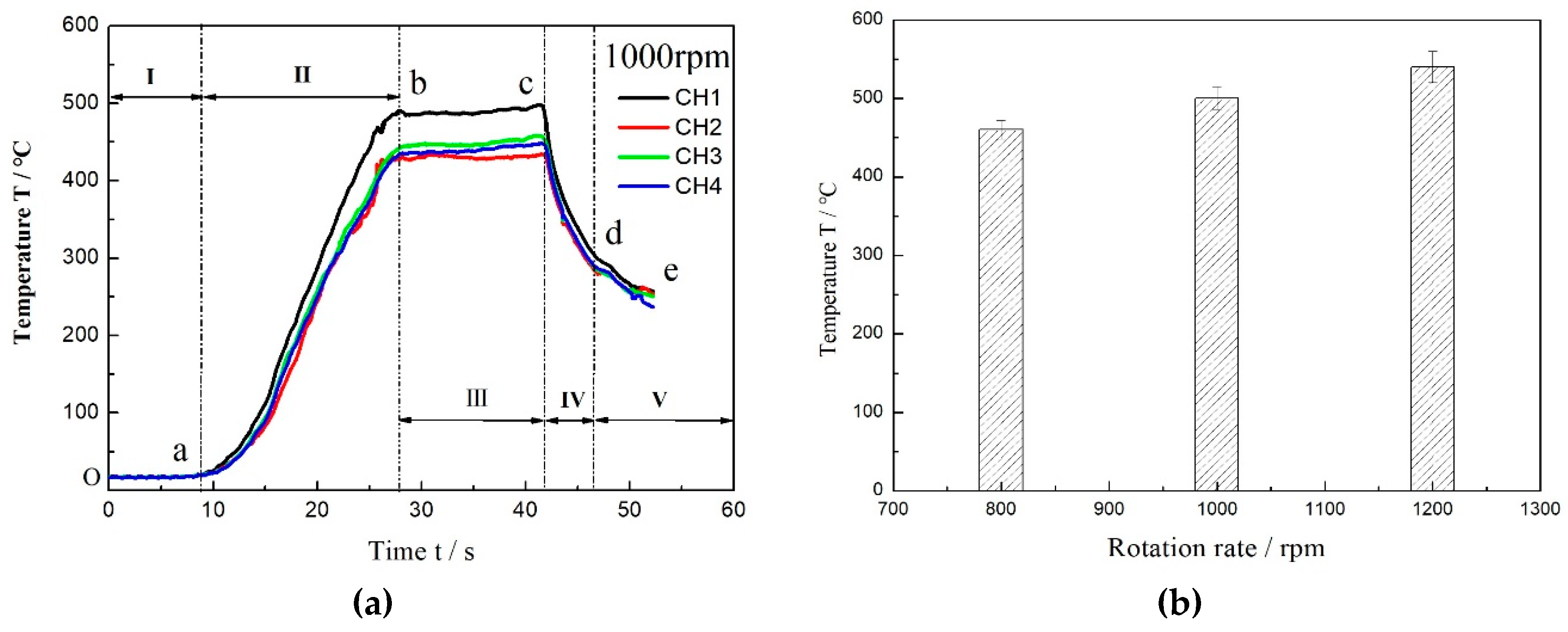
3.1.1. Welding Temperature Curve

Figure 4 shows the real-time temperature–time curves and histogram of the maximum welding temperature of the dissimilar Al/steel keyhole-free FSSW process. It can be seen that the temperature variation curves of the four thermocouple channels around the spot-welded joints are slightly different, but the curves are identical in shape, which shows that the temperature variation is in good agreement with the welding stages. According to the temperature curve, the welding process can be divided into five stages as follows, as shown in Figure 4a.
The welding initial stage (I): The point O is the starting point of welding, and the temperature of the sample is about 20 °C at room temperature. Starting from point O, the welding tool begins to rotate and plunge in stage Oa, but it is not in contact with the workpiece, so the sample temperature has not changed.
The warming-up stage (II): The temperature of the sample begins to rise rapidly in the ab stage. At this time, the tool pin begins to plunge into the workpiece, and the shoulder then contacts the surface of the steel plate. The temperature of the workpiece rises sharply due to friction heat generated by friction action. The higher heating rate vc = dT/dt indicates that the temperature rises very fast in this stage, and the maximum temperature reaches about 500 °C.
The welding stage (III): this stage, bc, is the stable stage of welding, and the temperature is still maintained at a maximum of about 500 °C and is almost constant. At this time, when the tool pin is retracted back, the contact between the shoulder and the workpiece is still stable. The friction heat is almost invariant, and the welding temperature is maintained near 500 °C.
The welding end stage (IV): The welding tool is lifted in stage cd, and the shoulder begins to detach from the workpiece surface. The workpiece temperature drops rapidly. The cooling rate vd = dT/dt is almost the same as the heating rate vc. This indicates that the friction heat between the shoulder and the workpiece surface is an important factor of the temperature rise in the FSSW welding process.
The cooling stage (V): This stage, de, is the cooling period of the specimen. At this stage, the FSSW welding process has ended and the workpiece temperature begins to decrease naturally. However, the cooling mode is mainly the heat conduction between the workpiece and the worktable and the heat convection and radiation between the specimen and the air. Therefore, the cooling rate is relatively slow, and the time is relatively long.
With the agitation of the mixing head and the increase of the welding temperature, the top steel plate and the bottom aluminum plate begin to deform and gradually soften under the action of the external force and friction heat. When the peak temperature of the workpiece on the outer side of the shoulder in the stable stage of welding reaches 500 °C, the temperature inside the joint will be higher during the dissimilar Al/steel FSSW process. At this time, the welding temperature is close to the melting point Tm = 660 °C of the Al alloy, which makes the Al alloy completely reach the thermoplastic state. With the stirring of the tool pin at such a high temperature, a plastic mixing of Al and steel components can be formed, which will lead to element diffusion, transition layers, and new phases. However, this mixing is only in the stirring area, as it is not mixed sufficiently in the action area of the shoulder. Instead, the bonding between metals is formed under the action of the shoulder extrusion force, similar to the rolling or extrusion process. At the same time, as can be found in Figure 4b, the maximum welding temperature increases gradually with the increase of rotational speed. Although a high welding temperature can increase the mixing and diffusion of the dissimilar Al/steel joint, too high a temperature can also lead to defects, such as excessive transition layer thickness and brittle phase formation.

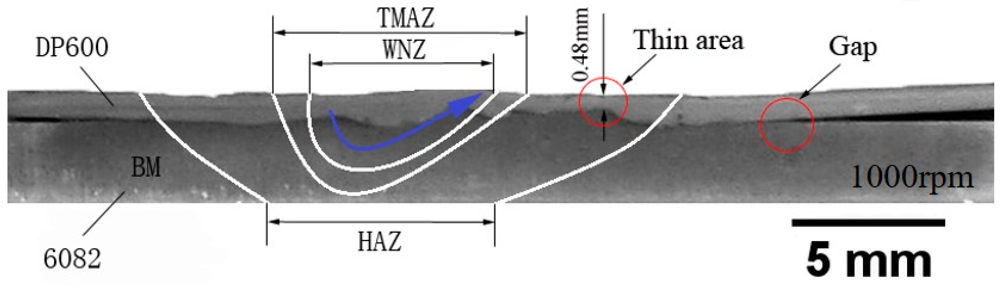
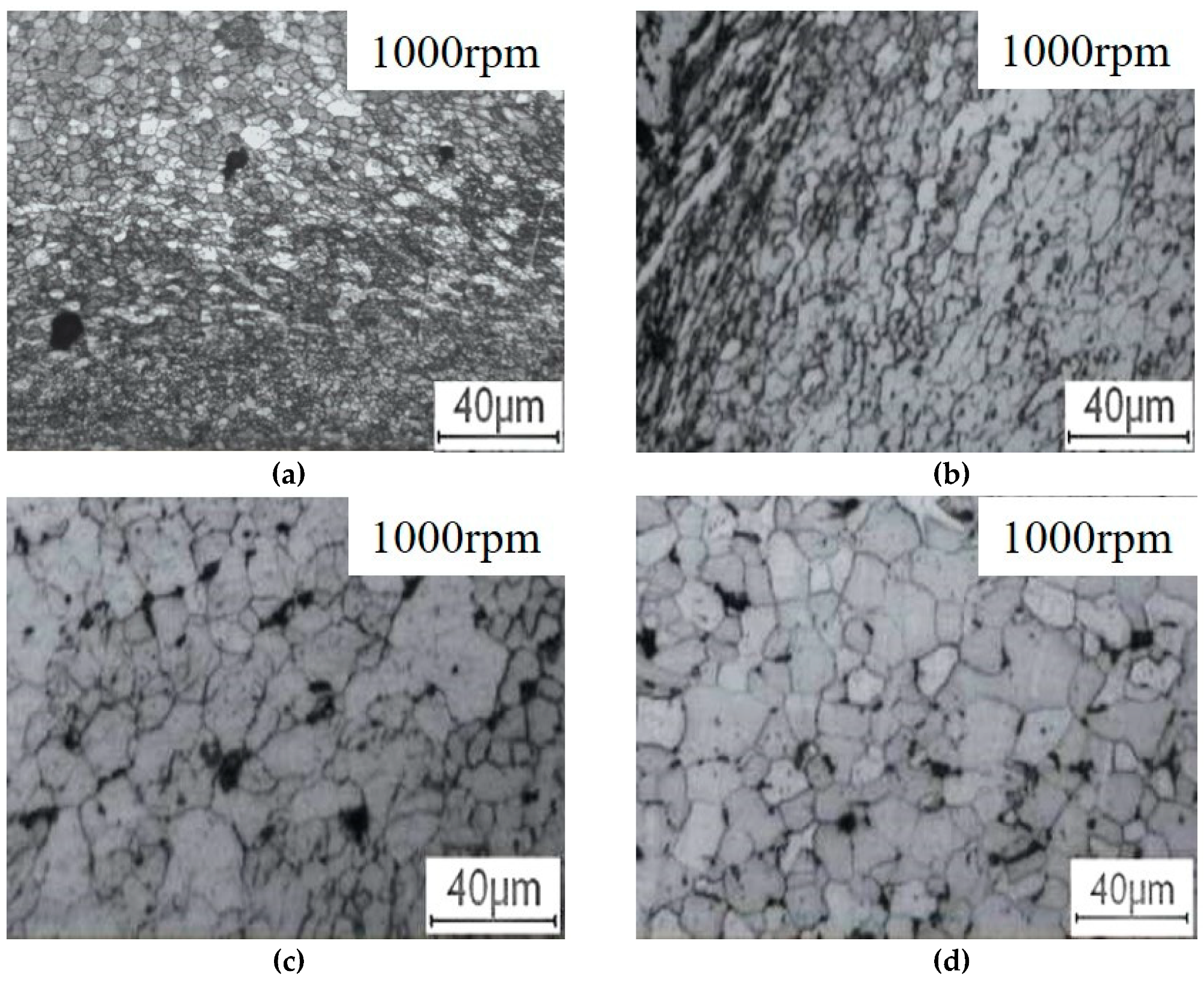
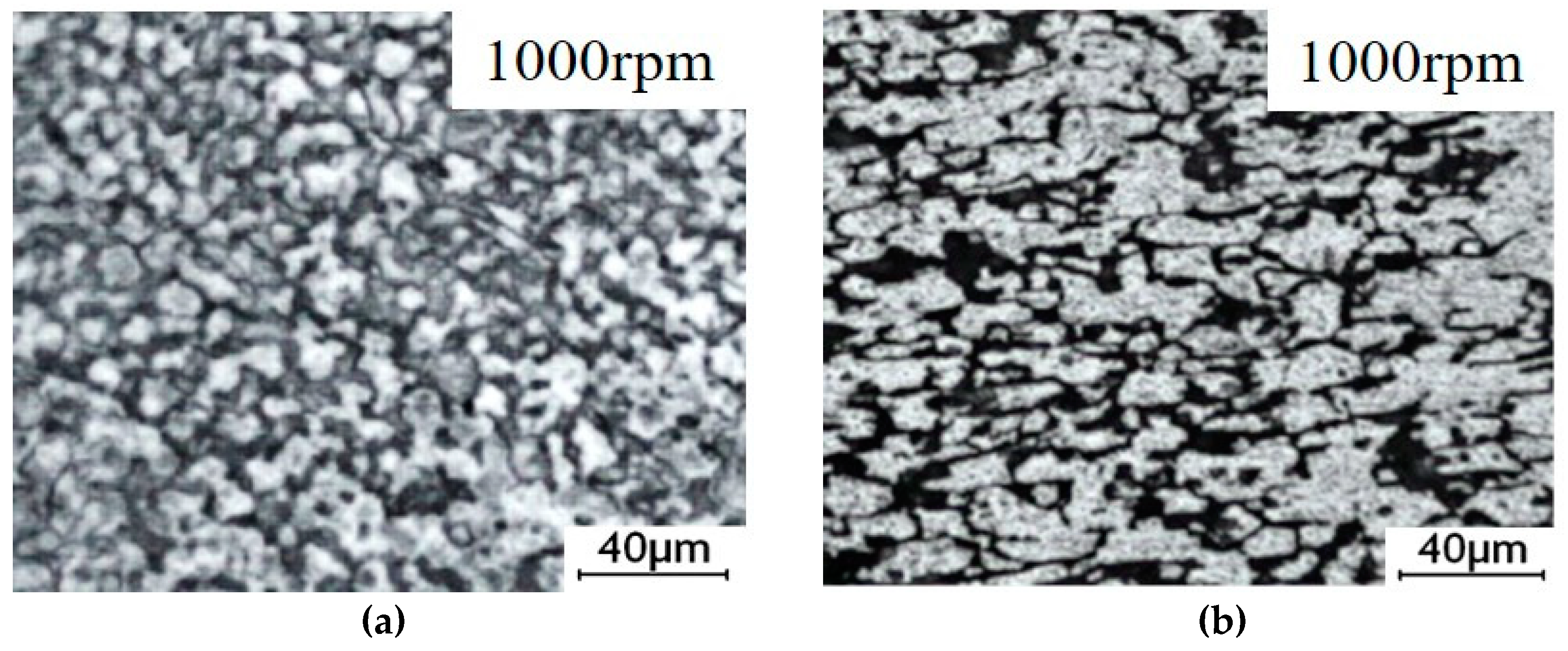
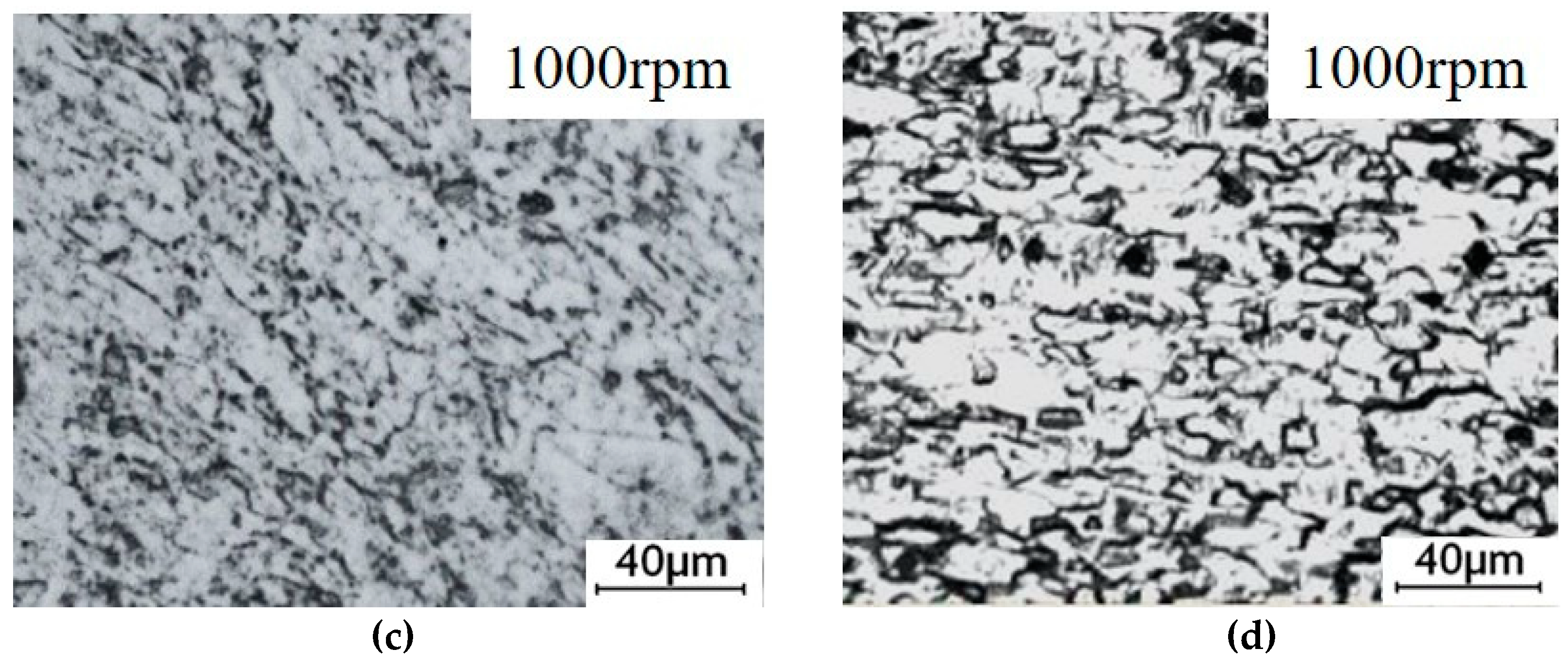
3.1.2. Microstructure

Figure 5 shows the sample of the keyhole-free FSSW joint of the dissimilar 6082 Al alloy and DP600 galvanized steel. It can be found that the keyhole was eliminated by the pin retraction technology in the welding process. Figure 6 shows the macroscopic morphology of the cross-section of the dissimilar Al/steel keyhole-free FSSW joint. The cross-sectional specimens can be divided into four zones: WNZ, TMAZ, HAZ, and BM. There is no keyhole on the cross-sectional specimens. A continuous inhomogeneous interface was formed at the Al/steel interface due to the effect of the stirring of the pin and the extrusion and friction of the shoulder of the tool. The walking path of the pin is shown by the blue arrow. The thickness of the steel plate was thinned from 1 mm to 0.48 mm, as shown in the thin area. There is a gap at the edge of the interface of the keyhole-free FSSW joint, which was the weak link in the spot-welded joints.
Figure 7 and Figure 8 show all regional microstructures of the steel and Al alloy in the keyhole-free FSSW joint, respectively. Figure 7a and Figure 8a show the fine equiaxed grains of the WNZ, which formed due to the recrystallization caused by the large plastic deformation and the friction heat [35]. The grain size of the WNZ decreases from 20 μm of BM to 1 μm. Figure 7b and Figure 8b show the elongated texture of the TMAZ, which was caused by large thermoplastic deformation [36]. Compared with the BM, the microstructure of the HAZ is slightly larger than that of the BM, as a result of the friction heat, as shown in Figure 7c,d and Figure 8c,d.
Figure 8d shows the microstructure of the 6082 Al alloy of BM zone, which has a typical basal texture. The grains of WNZ experienced a high temperature and strain rate under the combined action of the stirring pin and axial shoulder friction force, which caused the recrystallization of the grain and the redistribution of the enhancement phase and finally obtained the dynamic recrystallization grain, as shown in Figure 8a. The grain size of the WNZ decreases from 30 μm of BM to 5 μm. The width of the TMAZ is narrower, and the zone is partially plastic deformation due to the indirect agitation of the stirring pin. The temperature in the TMAZ is very close to that in the WNZ, so the grains of the recrystallization are shown in Figure 8b. The HAZ is only affected by the thermal cycle, so only the grain growth can be seen in Figure 8c.
Compared to Figure 7 and Figure 8, the deformation of steel is more intense than that of Al. As shown in Figure 7b, the grains of steel at the TMAZ, located underneath the pin, exhibited greater elongation directly beneath the full penetration of the pin than that shown in Figure 8b. This phenomenon is caused by the difference of the compressive stirring force. The stirring force at the TMAZ in Figure 7b is higher than that in Figure 8b, so the grain deformation of steel is more serious than that of Al.

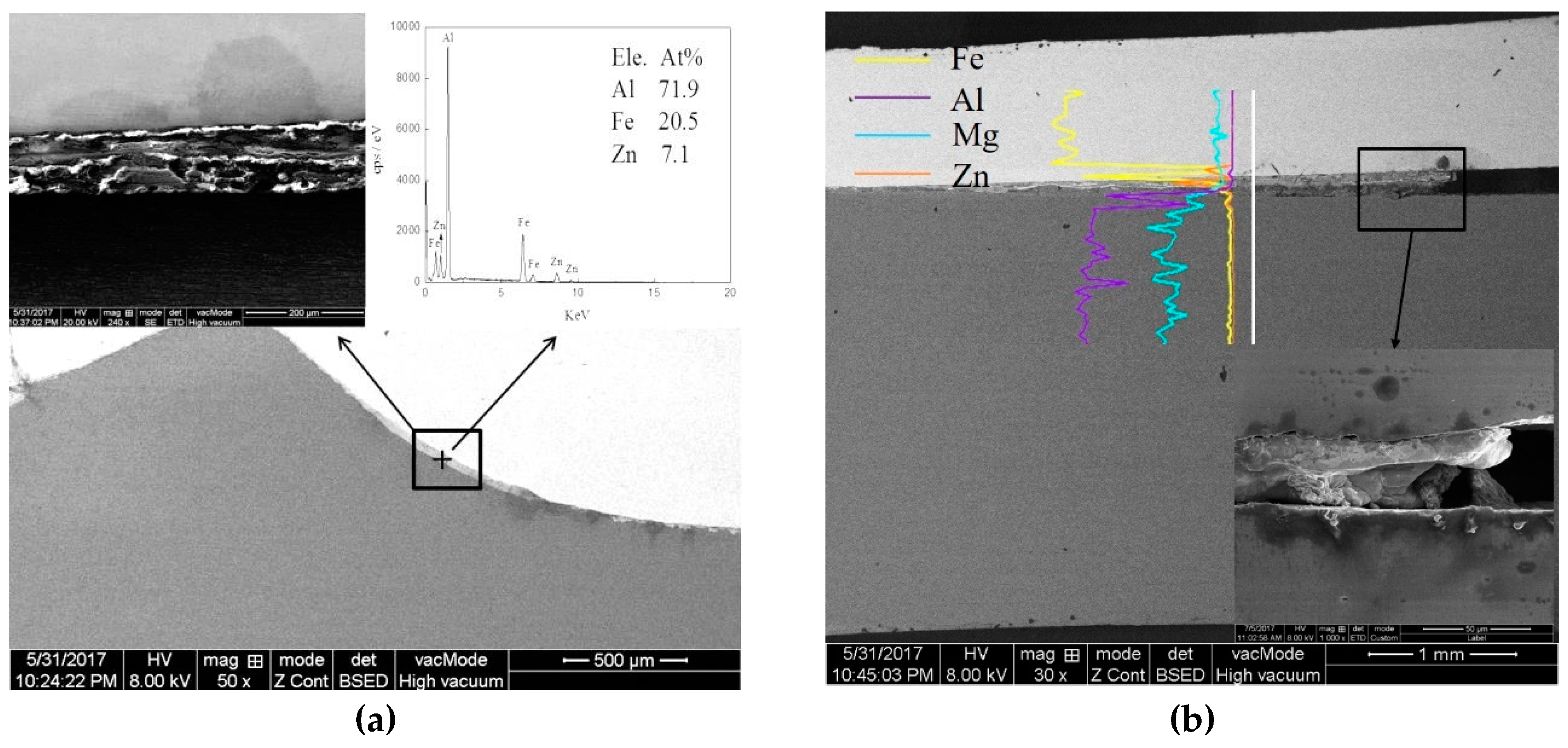
3.1.3. Interface Behavior

Figure 9 shows the micromorphology and EDS of the interface of the keyhole-free FSSW joint at the center and edge areas. In Figure 9a, the metal interlayer with discontinuous length and uneven thickness can be observed at the Al/steel interface. The metal interlayer is a transition layer composed of IMCs [11], which can be observed by local magnification of the metal interlayer region, as shown in the upper left corner in Figure 9a. The elements and their content were quantitatively analyzed by spot scanning the IMC layer, as shown in the upper right corner in Figure 9a. The IMC layer mainly contained Al, Fe, and Zn elements, and their contents were approximately 71.9%, 20.5%, and 7.1%, respectively. It can be concluded that the IMCs were mainly composed of Al, Fe, and Zn elements. There was an IMC layer at the interface at the edge of the keyhole-free FSSW joint, as shown in Figure 9b. It can be seen that the IMCs were not filled sufficiently at the interface gap, as shown in the lower right corner in Figure 8b. The interfacial bonding was poor and some of them became unbound [37,38]. The element diffusion was qualitatively analyzed by line scanning at the interface, as shown in the EDS at the interface in Figure 9b. It can be observed that the Fe, Al, and Mg elements linearly attenuated at the interface. However, the Zn element increased significantly at the interface. The zinc coating of DP600 galvanized steel participated in the interfacial reaction, resulting in the diffusion and increase in Zn in the interfacial layer [13].
The transition layer was further magnified and analyzed by EDS in Figure 10. Figure 10a shows the microstructure and EDS from the spot scans of the interface layer in the keyhole-free FSSW joint in the center area. The color of the interface transition layer is different from that of the matrix, and the thickness was approximately 15 μm [11]. The elements of the three atlases at points 1, 2, and 3 were quantitatively analyzed, as shown in the lower left corner of Figure 10a. The elements of the three spots in 1, 2, and 3 were mainly Al, Fe, and Zn. As the boundary of the interface became closer, the content of Zn increased, and the content of Fe decreased [13]. This indicates that the composition of the interface layer changed, and the transformed IMCs were also different [13,37,38,39,40]. Figure 10b shows the microstructure and EDS of the line-scanning analysis of the interface layer of the keyhole-free FSSW joint at the edge area. It can be found that the Fe, Al, Mg and Zn elements were staggered in the interface layer. This composition difference led to different IMCs, which had a non-uniform composition and content [13,37,38,39,40].
Figure 11 shows the micromorphology and EDS of the Al/steel interface in WNZ. The cloud cluster-like chaotic microstructure at the Al/steel interface can be found in the stirring zone. The elements of Fe and Al are distributed alternately with streamlined lines [10]. Meanwhile, the elements of Mg, Cu, Si and Zn were also unevenly distributed. This indicates the stratified intersecting and inhomogeneous mixing of the Al alloy and steel plates [10,41]. The stirring of the pin was uneven for the material in the welding process. The material only reached the thermoplastic state during the short welding time and fast cooling rate, which led to the mechanical mixing of Al and steel components.
Figure 12 shows the XRD spectrum of the cross-section of the dissimilar Al/steel keyhole-free FSSW joint. It can be found that IMC FeAl3 is formed at the Al/steel interface, as analyzed by the above elemental diffusion. Fereiduni et al. [38] also obtained an IMC with a similar atomic ratio at the interface layer. Due to the diffusion of the Zn element in the galvanized coating, the Zn element dissolved into the Al matrix to form phase AlZnx, and form IMC FeAl3Znx with IMC FeAl3 [13,37,38]. The Zn element diffused to the lattice space, and its elemental content was rather unstable [4]. At the same time, The IMC FeAl3 formed under different welding parameters is the same, but the content is different. With the increase of rotation speed, the welding temperature becomes higher, and the stirring of joints becomes more sufficient; the content of IMC FeAl3 and the thickness of the transition layers formed at a high temperature also increase.

3.2. Impact Properties

3.2.1. Impact Energy

The impact tests on the keyhole-free FSSW specimens with welding parameters of 800 rpm, 1000 rpm, and 1200 rpm were carried out to measure the impact toughness of the dissimilar Al/steel keyhole-free FSSW joint. The calculation formula for impact energy is as follows:
E = P × D × ( c o s φ c o s α )
where E is the impact energy, P is the weight of the pendulum hammer, D is the distance between the center of the shaft and the center of gravity of the pendulum hammer, α is the starting angle of the pendulum hammer, and φ is the end angle of the pendulum hammer.
Parameters P, D and α are the fixed constants given by the equipment, and their values are 26.63 kgf, 0.6340 m and 60°, respectively. The impact test parameters and the impact energy are shown in Table 3. Table 3 shows that the impact toughness of the specimen with the welding parameter of 1000 rpm is the best, with an impact energy of approximately 42 J. However, the impact energy of the other two specimens is similar, approximately 32 J.

3.2.2. Load-Displacement Curves of Impact

Figure 13 shows the load-displacement curves and the histogram of the impact properties of the dissimilar Al/steel keyhole-free FSSW joint. The maximum load of the curve is the maximum impact load Fm, as the vertex of the dotted line in Figure 13a. The area integral of the left half of the dotted line is the crack generation energy Ei, as shown in the yellow area in Figure 13a. The area integral of the right half of the dotted line is the crack propagation energy Ep, as shown in the blue area in Figure 13a. The area integral of the load-displacement curves of impact is the impact energy E = Ei + Ep. It can be found in Figure 13a that the maximum impact loads of the three specimens are almost the same, approximately 55 kN. The specimen with a welding parameter of 1000 rpm had the largest impact deformation and the best impact toughness, which illustrates that the factor affecting the size of the impact energy is not the maximum impact load but the maximum impact deformation. In addition, the integral impact energy of the load-displacement curve approximately agrees with the calculated impact energy. At the same time, it can be found in Figure 13b that the maximum impact deformation directly reflects the crack propagation energy. The pre-crack generation energy is almost the same and cannot affect the maximum impact energy to a great extent. However, the post-crack propagation energy substantially affects the impact toughness. There is an internal relationship between the crack propagation energy and impact deformation. The greater the crack propagation energy is, the longer the crack propagation, the greater the impact deformation, the better the impact toughness, and vice versa.

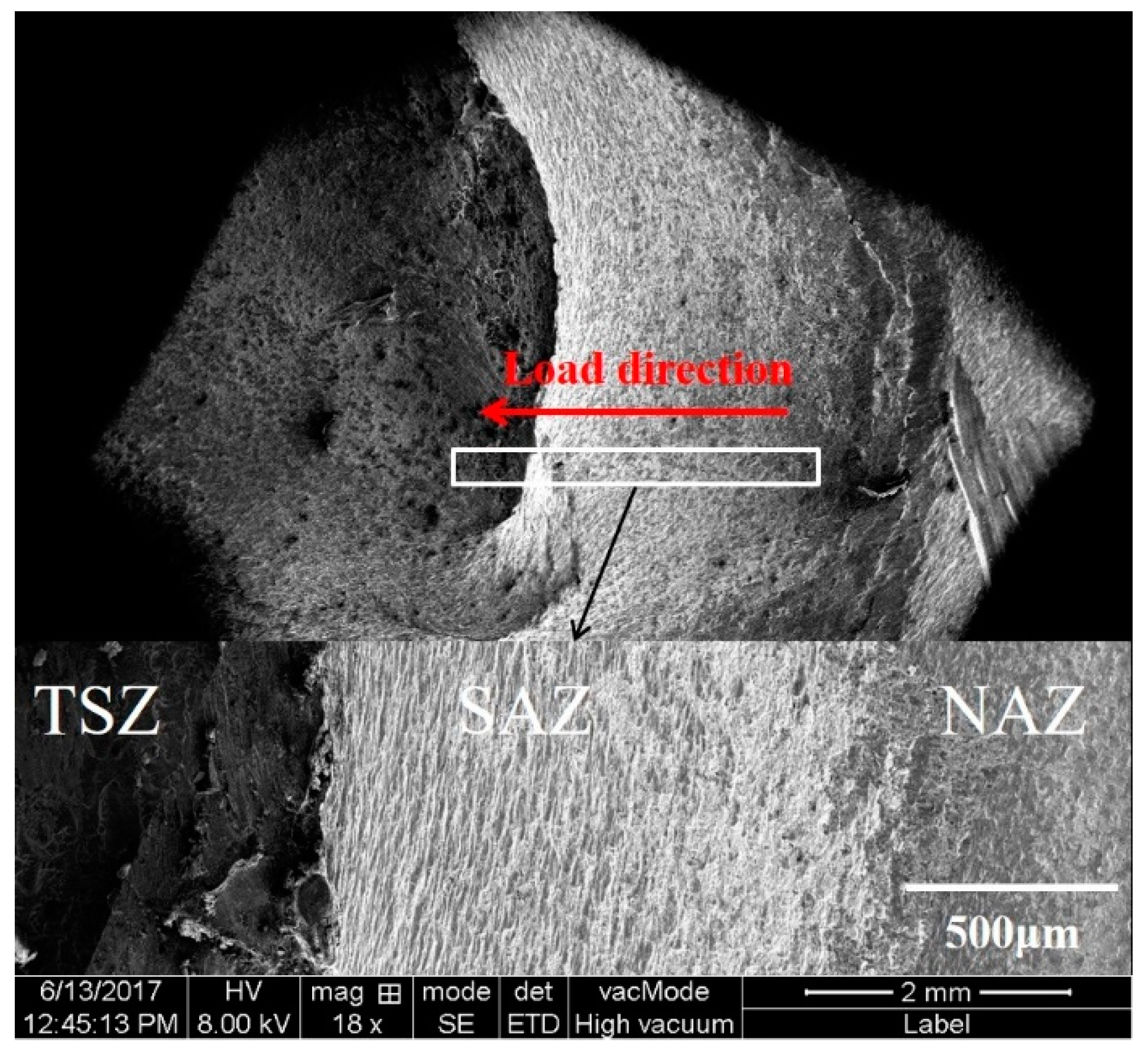
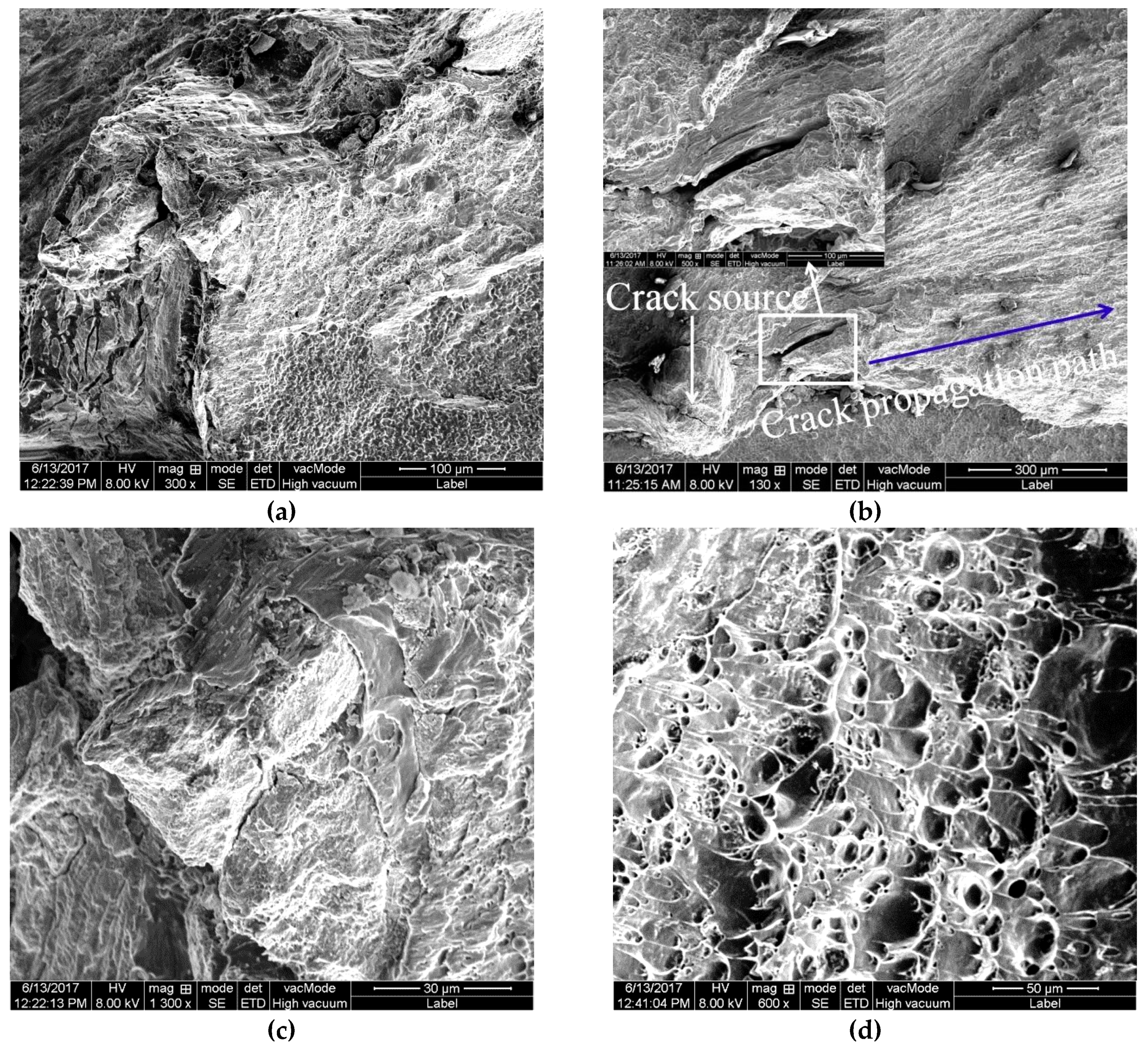
3.2.3. Impact Fracture

This impact test is based on the lap-shear test, as show in Figure 3. Although the welding parameters and impact energy of each group of samples are different, the fracture morphology rules under different welding parameters are consistent. The joint fracture of the Al side, with welding parameters at 1000 rpm, was selected as the object of observation and analysis. Figure 14 shows the macroscopic morphology of impact fracture of the dissimilar Al/steel keyhole-free FSSW joint. It can be found that the impact fracture morphology was diverse and uneven [13]. The magnification figure of the white rectangle area in Figure 14 is shown at the bottom of Figure 14. According to the welding process and connection mode, the impact fracture morphology is divided into the three zones noted as the non-action zone (NAZ), shoulder action zone (SAZ), and the stir zone (TSZ). The NAZ is weakly connected, and the fracture shows a shallow dimple-like morphology [11,42,43,44,45], which is not affected by the plunge force of the shoulder. This is the edge of the keyhole-free FSSW joint shown in Figure 8b, where the IMCs were not completely filled. Therefore, the cracks develop from the gaps and propagate into the weld [37,42,43,44,45]. SAZ has a deeper dimple and stronger connection [42,43,44,45], which is affected by the dual effects of the friction heat and the plunge force of the shoulder. That is, the interface junction area of the keyhole-free FSSW joint in Figure 9b is in this zone. TSZ has the strongest connection strength and is affected by the stirring and heat effect of the pin, i.e., the cloud cluster-like microstructure of the keyhole-free FSSW joint shown in Figure 11.
Figure 15 shows the microscopic fracture morphology for the TSZ of a dissimilar Al/steel keyhole-free FSSW joint. Figure 15a shows the whole picture of the fracture morphology of the TSZ. It can be found that the crack started at a point in the brittle phase and expanded outward along the blue line in the TSZ, as shown in Figure 15a [10]. After the crack was generated, it first extended along the brittle phase. During the large deformation during impact, the large impact energy causes the brittle phase to crack, as shown in the upper left corner of Figure 15a. When there is no brittle phase in the crack extension zone, the crack can continue to expand along the plastic phase [11]. Figure 15b shows the brittle–ductile transition zone of the impact fracture in the TSZ. This zone illustrates the transition of the fracture mode from a brittle fracture to a ductile fracture. Further magnification of the brittle and ductile areas is shown in Figure 15c,d, respectively. Figure 15c shows a brittle cleavage fracture, whereas Figure 15d shows a ductile fracture with typical shear dimples [40,42]. It can be inferred that the impact fracture mode of the keyhole-free FSSW joint is the mixed ductile and brittle fracture mode [40,42]. Most of the impact energy is absorbed by the ductile fracture.
Figure 16 shows the EDS surface-scanning results of the impact fracture in the TSZ. The elements were unevenly distributed on the fracture surface, as shown in Figure 16. Therefore, many brittle phases existed at the fracture surface, as discussed above, such as AlZnx, FeAl3, and FeAl3Znx [13,37,38]. This is another important cause of crack formation.
From the above analysis, it can be seen that during the impact fracture of dissimilar Al/steel joints, the crack first starts from the weak zone of the joint, such as brittle phase and the gap. At the same time, the crack first propagates along the brittle zone, forming a dissociation fracture, and then propagates along the ductile zone, forming a ductile fracture. The intermetallic transition layer provides the environment for brittle crack growth, while the Al and steel matrix provide the buffer for ductile crack growth. Therefore, the impact fracture of the dissimilar Al/steel keyhole-free FSSW joint is the mixed ductile and brittle fracture mode, in which the plastic fracture mode improves the fracture impact energy.

4. Conclusions

The keyhole-free spot-welding joints of the dissimilar 6082 Al alloy and DP600 galvanized steel were successfully fabricated by retractile keyhole-free FSSW. The keyhole was eliminated by pin retraction technology. The interface behavior and impact performance of the dissimilar Al/steel keyhole-free FSSW joints were studied and analyzed in combination with the keyhole-free FSSW process. Important conclusions are as follows:
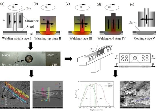
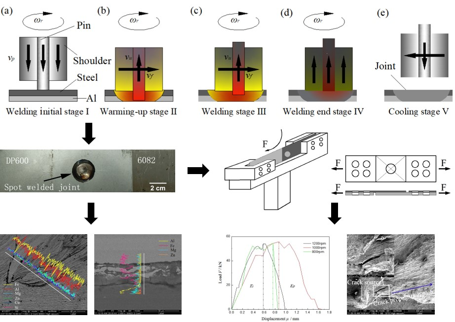
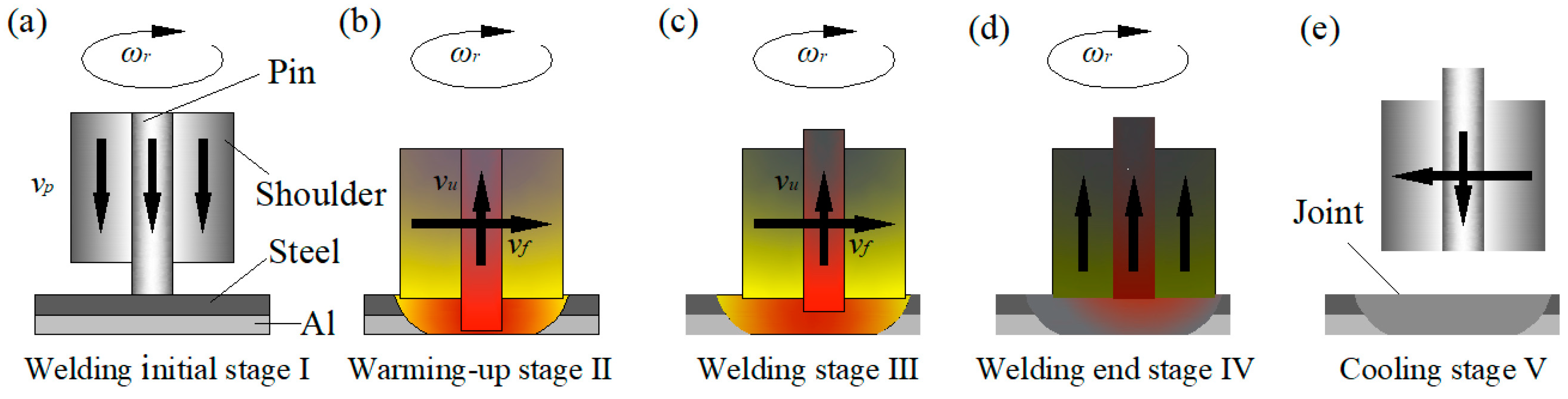
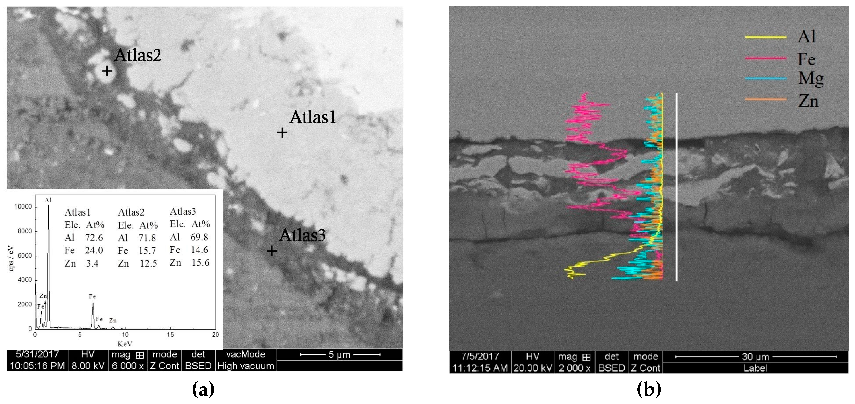
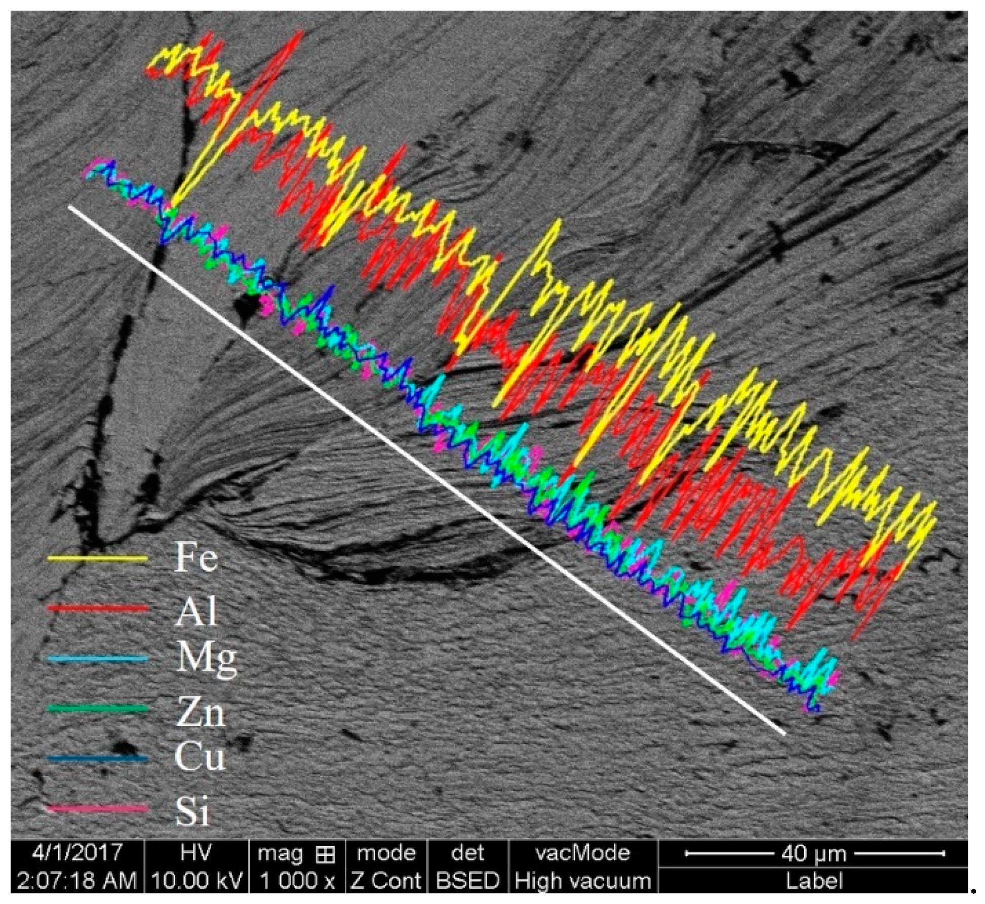
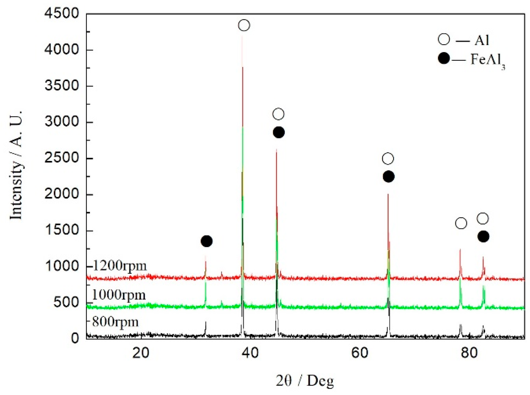
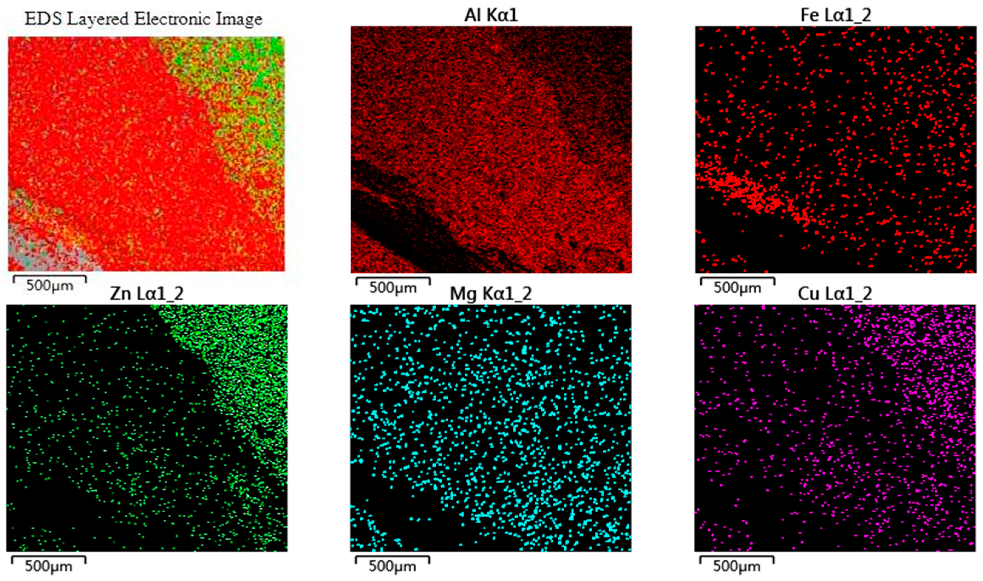
  • The maximum temperature of the periphery of the shoulder measured is about 500 °C, and fine equiaxed crystals are formed by dynamic recrystallization in WNZ, simultaneously accompanied by a cloud cluster-like mechanical mixing chaotic microstructure in TSZ. The Al/steel interface forms a transition layer composed of IMC FeAl3, which is formed at the Al/steel interface, and there is diffusion of Al and Fe elements on the transition layer. When the welding parameters are 1000 rpm, the thickness of transition layer is approximately 15 μm. The grain size of WNZ on the steel side decreases from 20 μm of BM to 1 μm, and the grain size of WNZ on steel side decreases from 30 μm of BM to 5 μm.
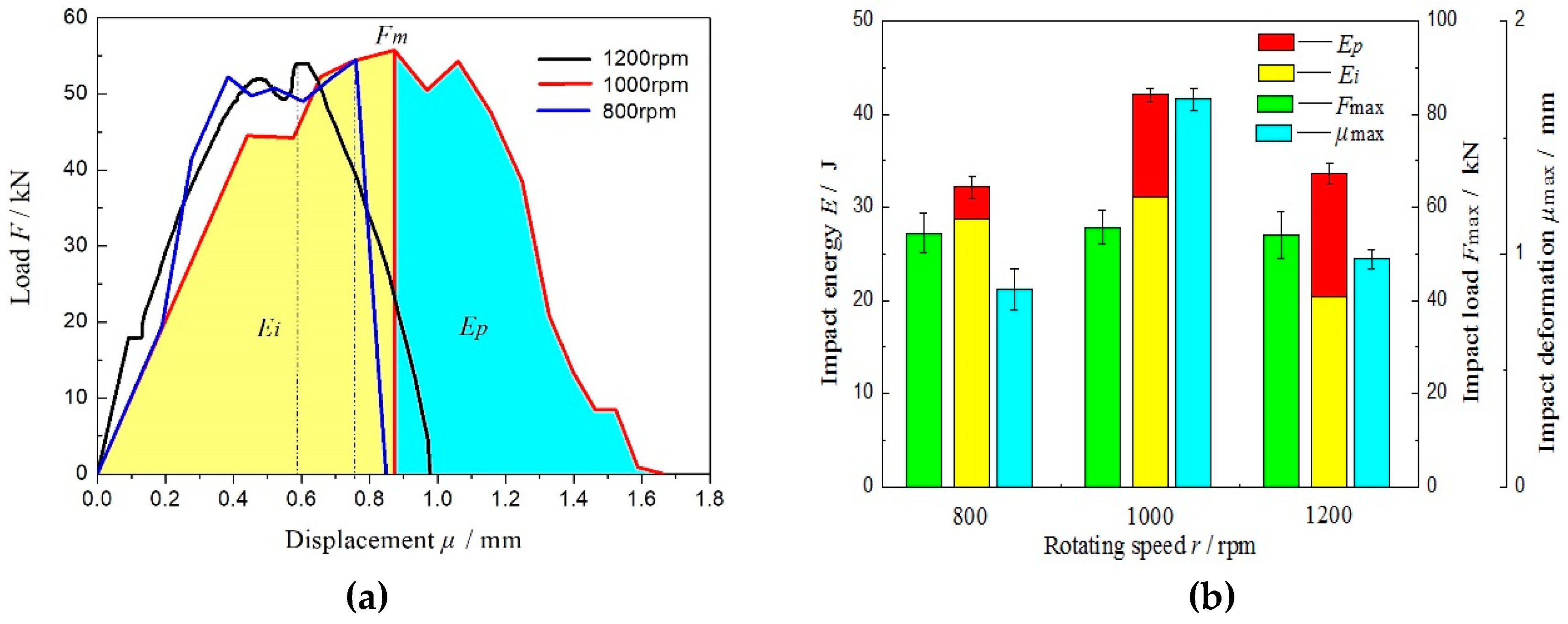
  • The impact toughness of the specimen with a welding parameter of 1000 rpm is the best, and the impact energy is approximately 42 J. The brittle IMCs are the crack source, and mixed ductile and brittle fractures with brittle–ductile transition zones are formed, in which the ductile fracture improves impact deformation and absorbs most of impact energy. To a certain extent, the maximum impact deformation directly reflects the post-crack propagation energy, which significantly affects the impact toughness. The greater the crack propagation energy, the longer the crack propagation, the greater the impact deformation, and the better the impact toughness, and vice versa.

Author Contributions

Z.Z., Y.Y. and X.W. designed and planned the experiment. Y.Y. made the tests and wrote the paper. Z.Z. modified the paper. H.Z. provided the funding acquisition.

Funding

This research was funded by the Aviation Science Fund of China (No. 201611U2001) and Major Science and Technology Project of Gansu Province (No. 18ZD2GC013).

Acknowledgments

This work was funded by the Aviation Science Fund of China (No. 201611U2001) and Major Science and Technology Project of Gansu Province (No. 18ZD2GC013).

Conflicts of Interest

The authors declare no conflict of interest.

References

  1. Piccini, J.M.; Svoboda, H.G. Effect of the Tool Penetration Depth in Friction Stir Spot Welding (FSSW) of Dissimilar Aluminum Alloys. Procedia Mater. Sci. 2015, 8, 868–877. [Google Scholar] [CrossRef] [Green Version]
  2. Xu, R.; Ni, D.; Yang, Q.; Liu, C.; Ma, Z. Pinless Friction Stir Spot Welding of Mg‒3Al‒1Zn Alloy with Zn Interlayer. J. Mater. Sci. Technol. 2016, 32, 76–88. [Google Scholar] [CrossRef]
  3. Piccini, J.M.; Svoboda, H.G. Effect of pin length on Friction Stir Spot Welding (FSSW) of dissimilar Aluminum-steel joints. Procedia Mater. Sci. 2015, 9, 504–513. [Google Scholar] [CrossRef] [Green Version]
  4. Boucherit, A.; Avettand-Fènoël, M.-N.; Taillard, R. Effect of a Zn interlayer on dissimilar FSSW of Al and Cu. Mater. Des. 2017, 124, 87–99. [Google Scholar] [CrossRef]
  5. Choi, D.-H.; Ahn, B.-W.; Lee, C.-Y.; Yeon, Y.-M.; Song, K.; Jung, S.-B. Formation of intermetallic compounds in Al and Mg alloy interface during friction stir spot welding. Intermetallics 2011, 19, 125–130. [Google Scholar] [CrossRef]
  6. Shen, Z.; Ding, Y.; Chen, J.; Gerlich, A. Comparison of fatigue behavior in Mg/Mg similar and Mg/steel dissimilar refill friction stir spot welds. Int. J. Fatigue 2016, 92, 78–86. [Google Scholar] [CrossRef]
  7. Kubit, A.; Kluz, R.; Trzepieciński, T.; Wydrzyński, D.; Bochnowski, W. Analysis of the mechanical properties and of micrographs of refill friction stir spot welded 7075-T6 aluminium sheets. Arch. Civ. Mech. Eng. 2018, 18, 235–244. [Google Scholar] [CrossRef]
  8. Xu, R.; Ni, D.; Yang, Q.; Liu, C.; Ma, Z. Influencing mechanism of Zn interlayer addition on hook defects of friction stir spot welded Mg–Al–Zn alloy joints. Mater. Des. 2015, 69, 163–169. [Google Scholar] [CrossRef]
  9. Garg, A.; Bhattacharya, A. Strength and failure analysis of similar and dissimilar friction stir spot welds: Influence of different tools and pin geometries. Mater. Des. 2017, 127, 272–286. [Google Scholar] [CrossRef]
  10. Chen, K.; Liu, X.; Ni, J. Keyhole refilled friction stir spot welding of aluminum alloy to advanced high strength steel. J. Mater. Process. Technol. 2017, 249, 452–462. [Google Scholar] [CrossRef]
  11. Hsieh, M.-J.; Lee, R.-T.; Chiou, Y.-C. Friction stir spot fusion welding of low-carbon steel to aluminum alloy. J. Mater. Process. Technol. 2017, 240, 118–125. [Google Scholar] [CrossRef]
  12. Bozzi, S.; Helbert-Etter, A.; Baudin, T.; Criqui, B.; Kerbiguet, J. Intermetallic compounds in Al 6016/IF-steel friction stir spot welds. Mater. Sci. Eng. A 2010, 527, 4505–4509. [Google Scholar] [CrossRef]
  13. Dong, H.; Chen, S.; Song, Y.; Guo, X.; Zhang, X.; Sun, Z. Refilled friction stir spot welding of aluminum alloy to galvanized steel sheets. Mater. Des. 2016, 94, 457–466. [Google Scholar] [CrossRef]
  14. Reimann, M.; Goebel, J.; Dos Santos, J.F. Microstructure and mechanical properties of keyhole repair welds in AA 7075-T651 using refill friction stir spot welding. Mater. Des. 2017, 132, 283–294. [Google Scholar] [CrossRef]
  15. Cao, J.; Wang, M.; Kong, L.; Zhao, H.; Chai, P. Microstructure, texture and mechanical properties during refill friction stir spot welding of 6061-T6 alloy. Mater. Charact. 2017, 128, 54–62. [Google Scholar] [CrossRef]
  16. Malik, V.; Sanjeev, N.; Hebbar, H.S.; Kailas, S.V. Time Efficient Simulations of Plunge and Dwell Phase of FSW and its Significance in FSSW. Procedia Mater. Sci. 2014, 5, 630–639. [Google Scholar] [CrossRef] [Green Version]
  17. Malik, V.; Sanjeev, N.; Hebbar, H.S.; Kailas, S.V. Finite Element Simulation of Exit Hole Filling for Friction Stir Spot Welding–A Modified Technique to Apply Practically. Procedia Eng. 2014, 97, 1265–1273. [Google Scholar] [CrossRef]
  18. D’Urso, G. Thermo-mechanical characterization of friction stir spot welded AA6060 sheets: Experimental and FEM analysis. J. Manuf. Process. 2015, 17, 108–119. [Google Scholar] [CrossRef]
  19. Malik, V.; Sanjeev, N.; Hebbar, H.S.; Kailas, S.V. Investigations on the Effect of Various Tool Pin Profiles in Friction Stir Welding Using Finite Element Simulations. Procedia Eng. 2014, 97, 1060–1068. [Google Scholar] [CrossRef] [Green Version]
  20. Siddharth, S.; Senthilkumar, T.; Chandrasekar, M. Development of processing windows for friction stir spot welding of aluminium Al5052/copper C27200 dissimilar materials. Trans. Nonferrous Met. Soc. China 2017, 27, 1273–1284. [Google Scholar] [CrossRef]
  21. Fanelli, P.; Vivio, F.; Vullo, V. Experimental and numerical characterization of Friction Stir Spot Welded joints. Eng. Fract. Mech. 2012, 81, 17–25. [Google Scholar] [CrossRef]
  22. Mandal, S.; Rice, J.; Elmustafa, A. Experimental and numerical investigation of the plunge stage in friction stir welding. J. Mater. Process. Technol. 2008, 203, 411–419. [Google Scholar] [CrossRef]
  23. Su, H.; Wu, C.S.; Bachmann, M.; Rethmeier, M. Numerical modeling for the effect of pin profiles on thermal and material flow characteristics in friction stir welding. Mater. Des. 2015, 77, 114–125. [Google Scholar] [CrossRef]
  24. He, X.; Gu, F.; Ball, A. A review of numerical analysis of friction stir welding. Prog. Mater. Sci. 2014, 65, 1–66. [Google Scholar] [CrossRef] [Green Version]
  25. Malafaia, A.; Milan, M.; Oliveira, M.; Spinelli, D. Evaluation of dynamic defect detection in FSSW welded joints under fatigue tests. Procedia Eng. 2010, 2, 1823–1828. [Google Scholar] [CrossRef] [Green Version]
  26. Venukumar, S.; Muthukumaran, S.; Yalagi, S.G.; Kailas, S.V. Failure modes and fatigue behavior of conventional and refilled friction stir spot welds in AA 6061-T6 sheets. Int. J. Fatigue 2014, 61, 93–100. [Google Scholar] [CrossRef]
  27. Joy-A-Ka, S.; Ogawa, Y.; Sugeta, A.; Sun, Y.; Fujii, H. Fatigue Fracture Mechanism on Friction Stir Spot Welded Joints Using 300 MPa-class Automobile Steel Sheets under Constant and Variable Force Amplitude. Procedia Mater. Sci. 2014, 3, 537–543. [Google Scholar] [CrossRef] [Green Version]
  28. Uematsu, Y.; Tokaji, K.; Tozaki, Y.; Nakashimac, Y. Fatigue behaviour of dissimilar friction stir spot weld between A6061 and SPCC welded by a scrolled groove shoulder tool. Procedia Eng. 2010, 2, 193–201. [Google Scholar] [CrossRef] [Green Version]
  29. Cui, H.; Xie, G.; Luo, Z.; Ma, J.; Wang, G.; Misra, R. The microstructural evolution and impact toughness of nugget zone in friction stir welded X100 pipeline steel. J. Alloy. Compd. 2016, 681, 426–433. [Google Scholar] [CrossRef]
  30. Xie, G.; Cui, H.; Luo, Z.; Misra, R.; Wang, G. Asymmetric distribution of microstructure and impact toughness in stir zone during friction stir processed a high strength pipeline steel. Mater. Sci. Eng. A 2017, 704, 401–411. [Google Scholar] [CrossRef]
  31. Sahu, P.K.; Pal, S. Mechanical properties of dissimilar thickness aluminium alloy weld by single/double pass FSW. J. Mater. Process. Technol. 2017, 243, 442–455. [Google Scholar] [CrossRef]
  32. Ding, J.; Oelgoetz, P. Auto-adjustable tool for friction stir welding. U.S. Patent 5,893,507A, 13 April 1999. [Google Scholar]
  33. Piccini, J.M.; Svoboda, H.G. Tool geometry optimization in friction stir spot welding of Al-steel joints. J. Manuf. Process. 2017, 26, 142–154. [Google Scholar] [CrossRef]
  34. Xie, G.; Cui, H.; Luo, Z.; Yu, W.; Ma, J.; Wang, G. Effect of Rotation Rate on Microstructure and Mechanical Properties of Friction Stir Spot Welded DP780 Steel. J. Mater. Sci. Technol. 2016, 32, 326–332. [Google Scholar] [CrossRef]
  35. Wang, L.; Xie, L.; Lv, Y.; Zhang, L.-C.; Chen, L.; Meng, Q.; Qu, J.; Zhang, D.; Lu, W. Microstructure evolution and superelastic behavior in Ti-35Nb-2Ta-3Zr alloy processed by friction stir processing. Acta Mater. 2017, 131, 499–510. [Google Scholar] [CrossRef] [Green Version]
  36. Cho, H.-H.; Kang, S.H.; Kim, S.-H.; Oh, K.H.; Kim, H.J.; Chang, W.-S.; Han, H.N. Microstructural evolution in friction stir welding of high-strength linepipe steel. Mater. Des. 2012, 34, 258–267. [Google Scholar] [CrossRef]
  37. Ding, Y.; Shen, Z.; Gerlich, A. Refill friction stir spot welding of dissimilar aluminum alloy and AlSi coated steel. J. Manuf. Process. 2017, 30, 353–360. [Google Scholar] [CrossRef]
  38. Fereiduni, E.; Movahedi, M.; Kokabi, A. Aluminum/steel joints made by an alternative friction stir spot welding process. J. Mater. Process. Technol. 2015, 224, 1–10. [Google Scholar] [CrossRef]
  39. Rao, H.M.; Yuan, W.; Badarinarayan, H. Effect of process parameters on mechanical properties of friction stir spot welded magnesium to aluminum alloys. Mater. Des. 2015, 66, 235–245. [Google Scholar] [CrossRef] [Green Version]
  40. Zhao, Y.; Ding, Z.; Shen, C.; Chen, Y. Interfacial microstructure and properties of aluminum–magnesium AZ31B multi-pass friction stir processed composite plate. Mater. Des. 2016, 94, 240–252. [Google Scholar] [CrossRef]
  41. Sarkar, R.; Pal, T.; Shome, M. Material flow and intermixing during friction stir spot welding of steel. J. Mater. Process. Technol. 2016, 227, 96–109. [Google Scholar] [CrossRef]
  42. Jamili-Shirvan, Z.; Haddad-Sabzevar, M.; Vahdati-Khaki, J.; Chen, N.; Shi, Q.; Yao, K.-F. Microstructure characterization and mechanical properties of Ti-based bulk metallic glass joints prepared with friction stir spot welding process. Mater. Des. 2016, 100, 120–131. [Google Scholar] [CrossRef]
  43. Shen, Z.; Yang, X.; Zhang, Z.; Cui, L.; Li, T. Microstructure and failure mechanisms of refill friction stir spot welded 7075-T6 aluminum alloy joints. Mater. Des. 2013, 44, 476–486. [Google Scholar] [CrossRef]
  44. Pabandi, H.K.; Movahedi, M.; Kokabi, A.H. A new refill friction spot welding process for aluminum/polymer composite hybrid structures. Compos. Struct. 2017, 174, 59–69. [Google Scholar] [CrossRef]
  45. Zheng, Q.X.; Feng, X.M.; Shen, Y.F.; Huang, G.Q.; Zhao, P.C. Dissimilar friction stir welding of 6061 Al to 316 stainless steel using Zn as a filler metal. J. Alloys. Compds 2016, 686, 693–701. [Google Scholar] [CrossRef]
Figure 1. The welding process of the dissimilar Al/steel retractile keyhole-free friction stir spot welding (FSSW), (a) welding initial stage I, (b) warming-up stage II, (c) welding stage III, (d) welding end stage IV, (e) cooling stage V.
Metals 09 00691 g001
Figure 2. Schematic diagram of thermocouple distribution around the dissimilar Al/steel keyhole-free FSSW joint.
Metals 09 00691 g002
Figure 3. Cantilever impact schematic of the dissimilar Al/steel keyhole-free FSSW joints.
Metals 09 00691 g003
Figure 4. The real-time temperature–time curves (a) and histogram of maximum welding temperature (b) of dissimilar Al/steel keyhole-free FSSW process.
Metals 09 00691 g004
Figure 5. Sample of a dissimilar Al/steel keyhole-free FSSW joint.
Metals 09 00691 g005
Figure 6. Macroscopic morphology of the cross-section of a dissimilar Al/steel keyhole-free FSSW joint.
Metals 09 00691 g006
Figure 7. The microstructure of the steel of the keyhole-free FSSW joint: (a) weld nugget zone (WNZ), (b) thermo-mechanically affected zone (TMAZ), (c) heat-affected zone (HAZ), and (d) base metal (BM).
Metals 09 00691 g007
Figure 8. The microstructure of the Al alloy of the keyhole-free FSSW joint: (a) WNZ, (b) TMAZ, (c) HAZ, and (d) BM.
Metals 09 00691 g008aMetals 09 00691 g008b
Figure 9. Micromorphology and energy-dispersive spectrometer (EDS) of the interface of the keyhole-free FSSW joint: (a) center area and (b) edge area.
Metals 09 00691 g009
Figure 10. Micromorphology and EDS of the transition layer of the keyhole-free FSSW joint: (a) center area and (b) edge area.
Metals 09 00691 g010
Figure 11. Micromorphology and EDS of the cloud cluster-like microstructure.
Metals 09 00691 g011
Figure 12. XRD spectrum of a cross-section of the dissimilar Al/steel keyhole-free FSSW joint.
Metals 09 00691 g012
Figure 13. Load-displacement curves (a) and histogram of impact properties (b) of the dissimilar Al/steel keyhole-free FSSW joint.
Metals 09 00691 g013
Figure 14. Macroscopic morphology of impact fracture of dissimilar Al/steel keyhole-free FSSW joint.
Metals 09 00691 g014
Figure 15. Microscopic fracture morphology of TSZ of dissimilar Al/steel keyhole-free FSSW joint: (a) whole picture, (b) brittle–ductile transition, (c) brittle cleavage fracture, and (d) ductile fracture.
Metals 09 00691 g015
Figure 16. EDS of the surface-scanning analysis of the impact fracture in STZ.
Metals 09 00691 g016
Table 1. The chemical composition of the 6082 Al alloy (in wt%).
6082SiFeCuMnMgCrZnTiOtherAl
Content0.7–1.30.500.100.4–1.00.6–1.20.250.200.100.15Bal.
Table 2. The chemical composition of DP600 galvanized steel (in wt%).
DP600CMnSiAlMoCrCuSPFe
Content0.091.840.360.050.010.020.030.0050.005Bal.
Table 3. The impact test parameters and the impact energy.
Rotation Speed
ω/rpm
End Angle
φ
Calculated Impact Energy
E/J
Integral Impact Energy
E/J
8004632.231.1
10004142.148.7
120045.333.734.0

