Main Issues in Quality of Friction Stir Welding Joints of Aluminum Alloy and Steel Sheets


Abstract
:1. Introduction
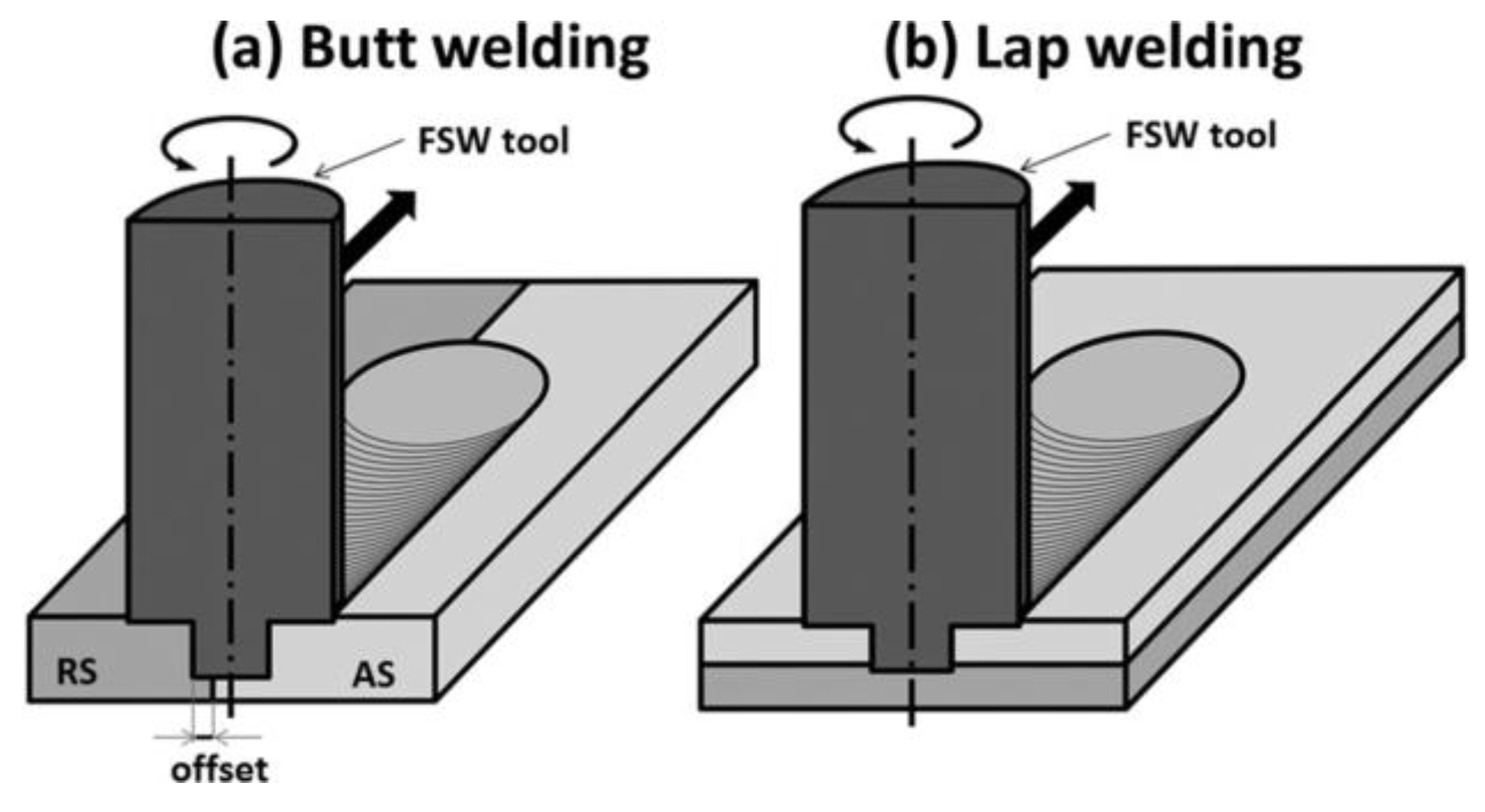
2. Issues in FSW of Aluminum Alloys to Steels
2.1. Intermetallic Compounds (IMCs)
2.2. FSW Parameters Affecting IMCs
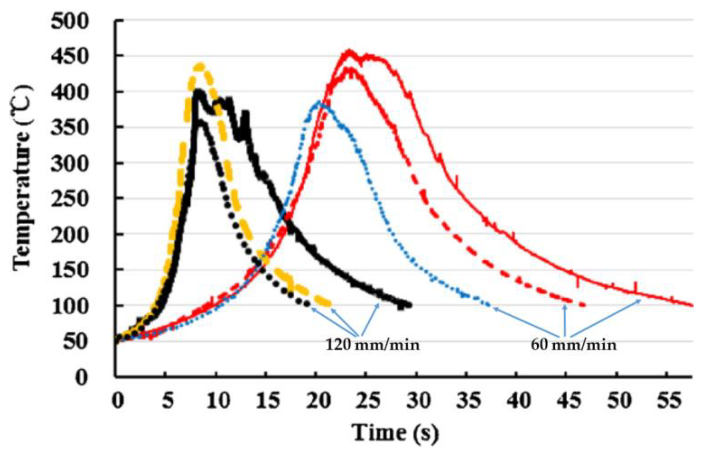
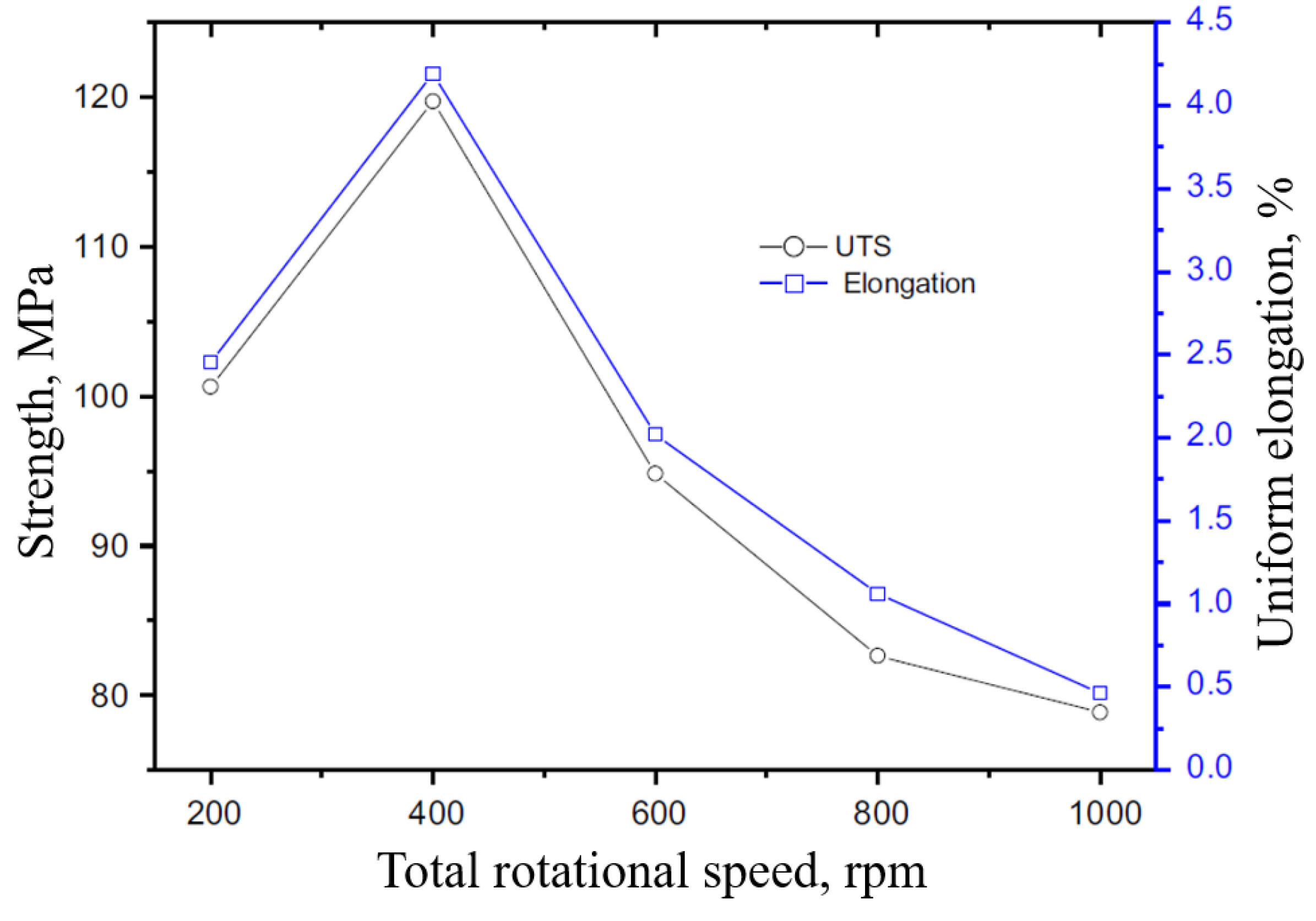
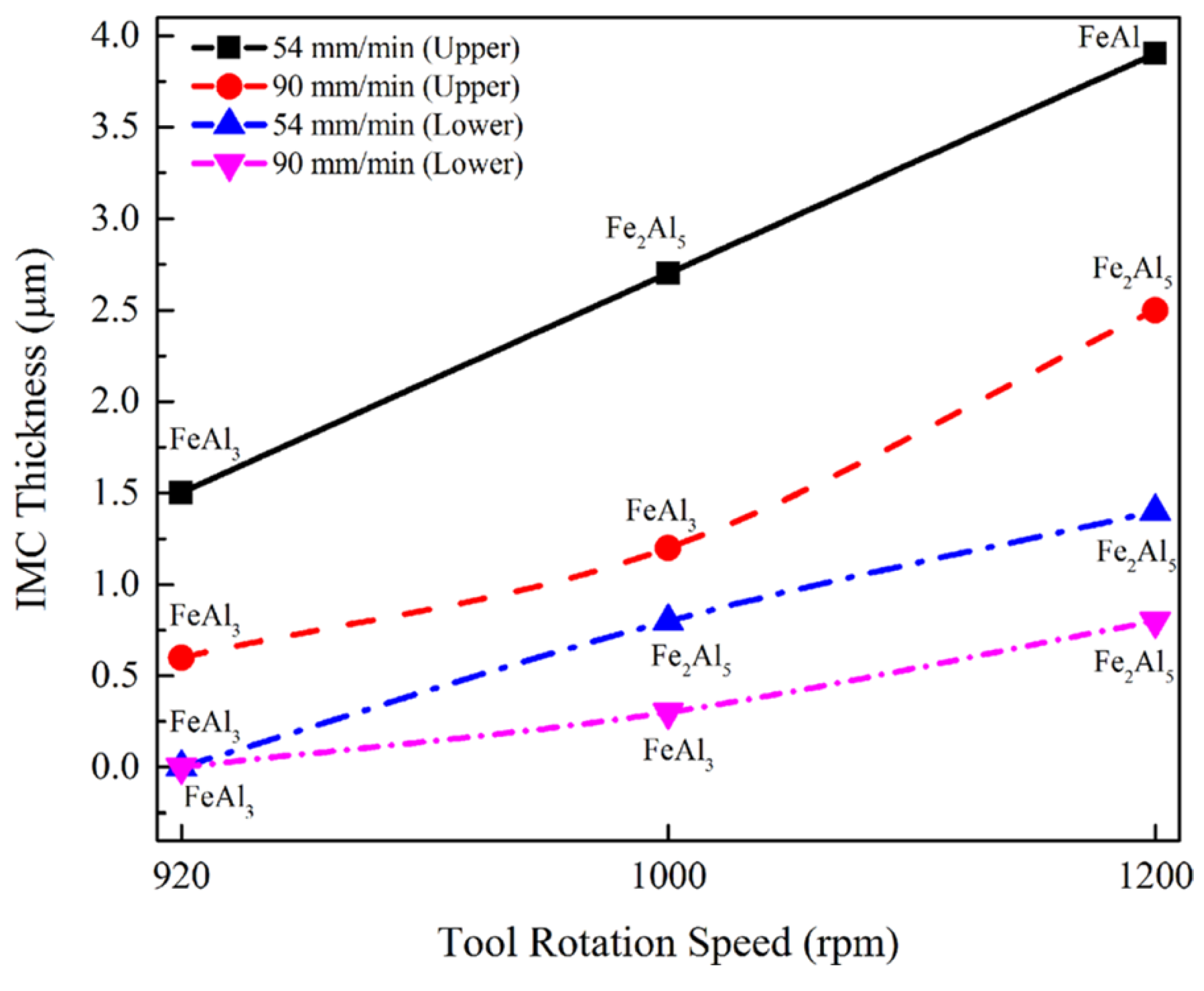
2.2.1. Rotational Speed and Welding Speed
2.2.2. Tool Geometry
2.2.3. Pin Depth, Plunge Depth, and Offset Distance
2.2.4. Tool Tilt Angle
3. Defects in FSW of Al/Steel Sheet Joints
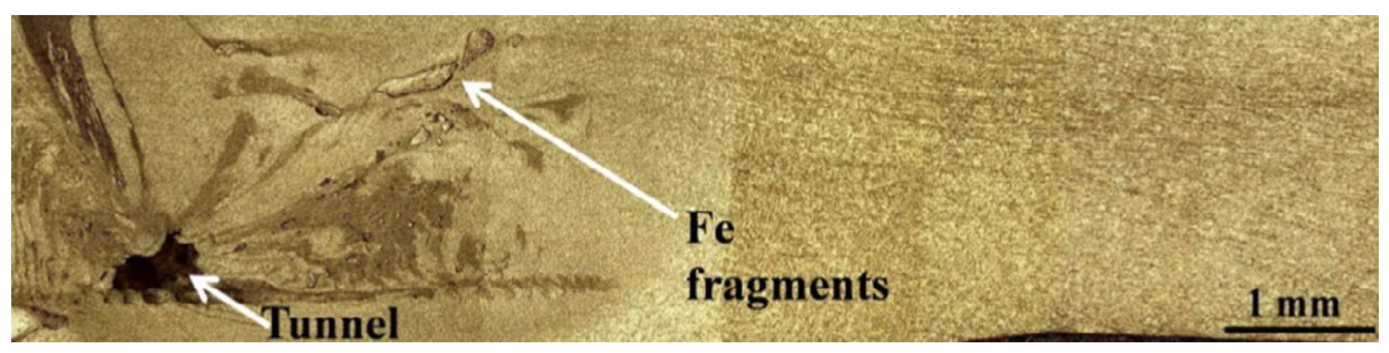
3.1. Tunnel Defect
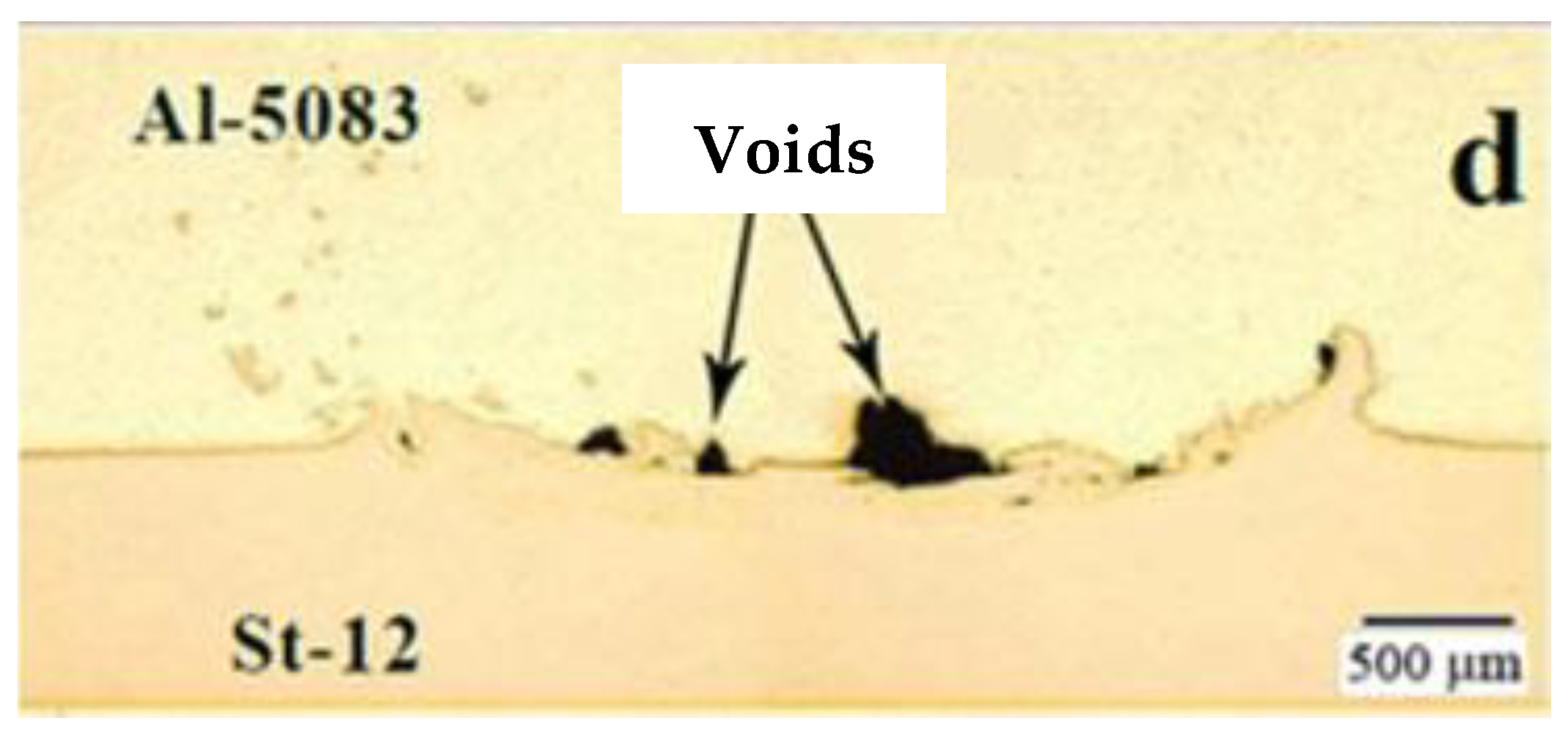
3.2. Voids
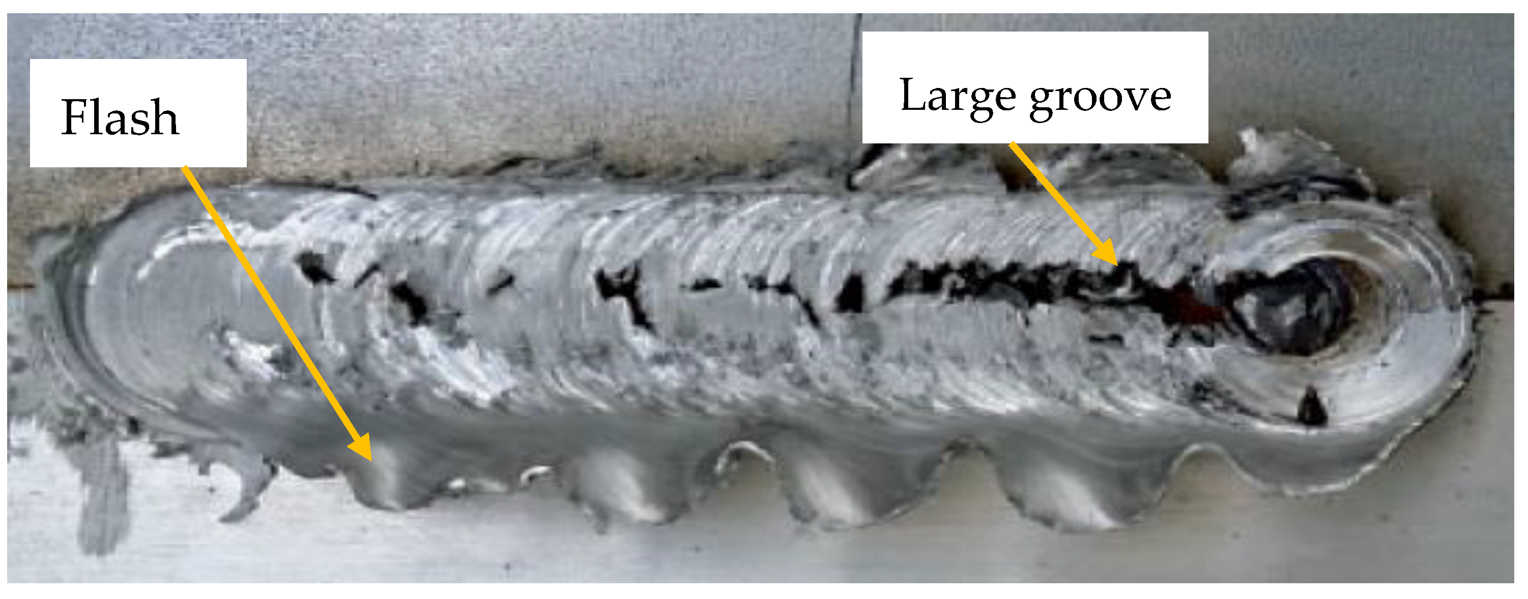
3.3. Surface Grooves and Flash Generation
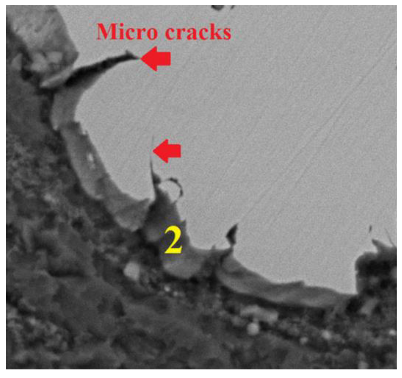
3.4. Microcracks
3.5. Recommendations and Challenges in FSW of Aluminum Alloys and Steels
4. Conclusions
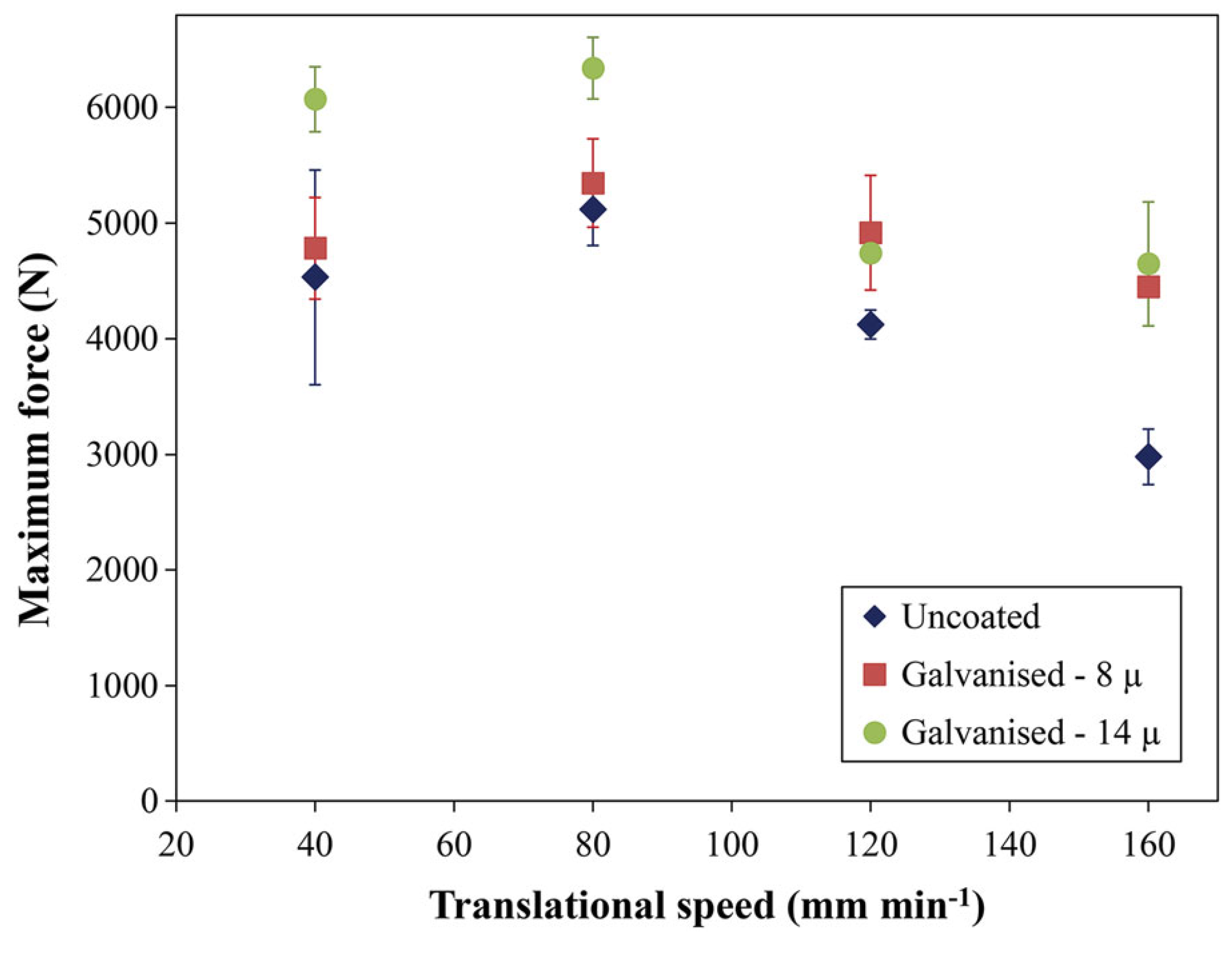
- Rotational speed and welding speed are the main factors responsible for heat generation during FSW of Al and steel. Improper process parameters can generate excessive or insufficient heat inputs, with the ensuing formation of defective or low-quality welded joints.
- IMCs of Al and Fe are defects usually found at the Al/steel interface as FeAl3, Fe2Al5, FeAl2, FeAl, and Fe3Al. IMCs initiate crack nucleation under external loading conditions, thus having a detrimental influence on weld strength.
- High rotational speed, low welding speed, and insertion of a tool pin into a steel sheet are often responsible for excessive heat generation in weld bead. The main consequence is the formation of thick and Al-rich IMCs, which significantly deteriorate the strength of welded joints.
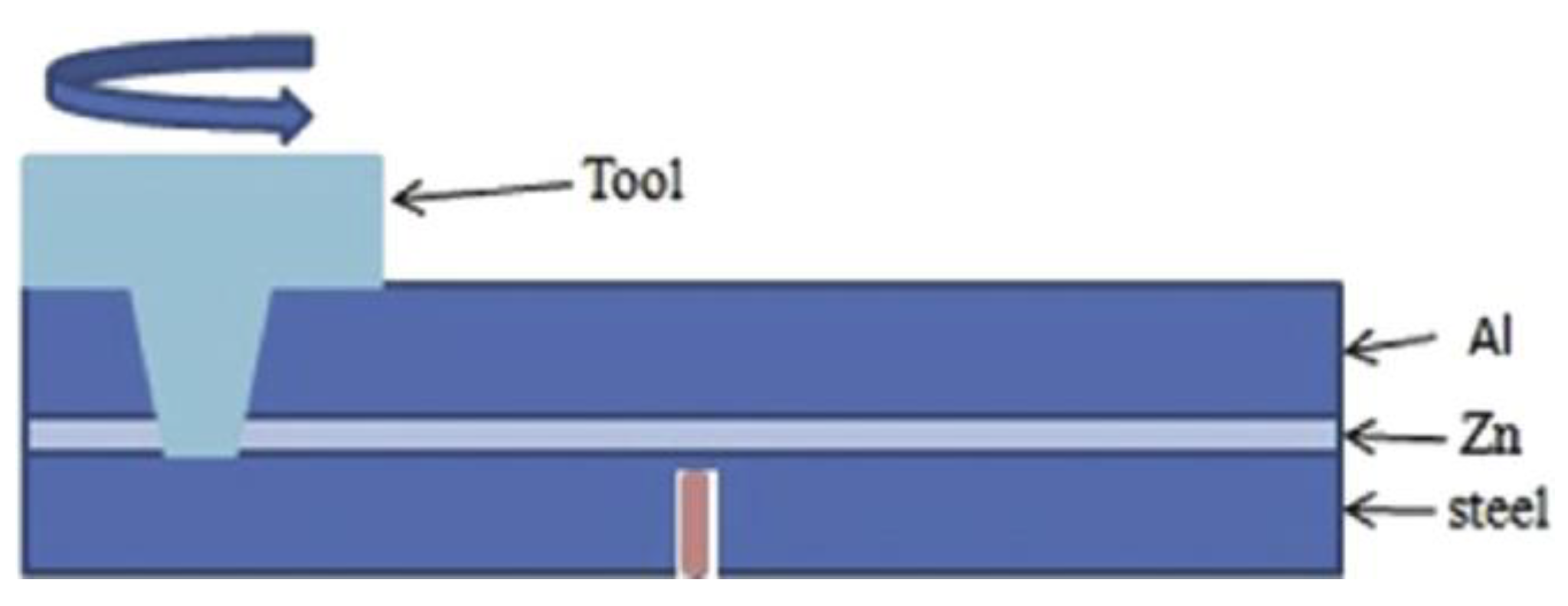
- The use of Zn or Ni layers between aluminum and steel sheets could help prevent the formation of Al/Fe IMCs.
- Improper process parameters, especially rotational speed and welding speed, could lead to the formation of tunnel, voids, large surface grooves, and microcracks.
- Welding parameters should develop enough heat inputs with the aim to properly plasticize metals and ensure deep intermixing.
Author Contributions
Funding
Acknowledgments
Conflicts of Interest
Appendix A

| Issues | Materials | Joint Configuration | Reference |
|---|---|---|---|
| Tunnel, groove | AA5754-H114/mild steel | Butt | [5] |
| Fe4Al13 | AA6082-T6/QSTE340TM steel | Lap | [9] |
| Cracks, voids, FeAl3 | AA6082-T6/Q235A steel | Lap | [13] |
| Tunnel, voids, Al5Fe2 | AA3003/mild steel | Butt | [14] |
| Voids, IMC | AA5083/St-12 steel | Lap | [15] |
| Tunnel, voids, microcracks, FeAl3 | AA5083-H321/316L stainless steel | Butt | [16] |
| Tunnel, FeAl, FeAl3, Fe2Al5 | AA5005/St-52 steel | Butt | [20] |
| Voids, FeAl, FeAl3 | AA5083/SS400 Steel | Lap | [21] |
| Voids, groove, Fe2Al5, FeAl3 | AA5083/SS400 Steel | Lap | [24] |
| FeAl, Fe2Al5, FeAl3 | AA5052/HSLA steel | Butt | [22] |
| Voids, groove, IMC | AA6061-T6/AISI304 steel | Lap | [26] |
| Voids, Al3.2Fe, Al5Fe2, Al6Fe | AA6082-T6/DP800 steel (Zn coated) | Lap | [28] |
| IMC | AA6061-T6/AISI304 steel | Lap | [29] |
| Al13Fe4, Al5Fe2, FeAl3, FeAl2 | Commercially pure aluminum/304 stainless steel | Butt | [30] |
| Cracks, FeAl2, Al13Fe4, Al5Fe2, FeAl3 | Commercially pure aluminum/304 stainless steel | Butt | [31] |
| Al13Fe4, Al5Fe | AA6061-T6/AISI 1018 steel | Butt | [32] |
| Cracks, FeAl3, Fe2Al5 | AA5083/316L stainless steel | Butt | [33] |
| Cracks, IMC | AA6061/TRIP steel | Butt | [41] |
| Tunnel, voids, Al6Fe, Al5Fe2 | AA5186/mild steel | Butt | [42] |
| Voids, FeAl, Fe3Al | AA1100/St-37 steel | Lap | [43] |
| Groove, microcracks, FeAl2 and FeAl3 | AA5052/HSLA steel | Butt | [44] |
| FeAl, Fe3Al | AA6061/TRIP 780/800 steel | Butt | [45] |
| Voids, groove, microcracks, FeAl, FeAl3 | AA6061/430 stainless steel | Butt | [46] |
| Voids, cracks, Fe4Al13 | AA5054/DP600 steel | Lap | [47] |
| IMC | AA6061-T6/ultra low carbon steel | Lap | [48] |
| Tunnel, voids, FeAl3, FeAl2 | AA1100/A441AISI steel | Butt | [52] |
| Voids, Al5Fe2, Al13Fe4 | AA5754/galvanized ultra-high strength | Lap | [58] |
| Cracks, IMC | AA6061-T6/Q235 steel | Butt | [59] |
| Al13Fe4, Al5Fe2 | AA1100-H24/low carbon steel (Zn-coated) | Lap | [60] |
| Tunnel, IMC | AA5083/A316L | Butt | [53] |
| Voids, Fe5Al8, FeAl | AA6082-T6/DP600 steel | Butt | [54] |
| Tunnel, voids, cracks, Al13Fe4, Al5Fe2 | AA-5050/304 stainless steel | Butt | [55] |
References
- Gullino, A.; Matteis, P.; D’Aiuto, F. Review of Aluminum-To-Steel Welding Technologies for Car-Body Applications. Metals 2019, 9, 315. [Google Scholar] [CrossRef]
- Patel, V.V.; Badheka, V.; Kumar, A. Friction stir processing as a novel technique to achieve superplasticity in aluminum alloys: Process variables, variants, and applications. Metall. Microstruct. Anal. 2016, 5, 278–293. [Google Scholar] [CrossRef]
- Simar, A.; Avettand-Fènoël, M.-N. State of the art about dissimilar metal friction stir welding. Sci. Technol. Weld. Join. 2017, 22, 389–403. [Google Scholar] [CrossRef]
- Yazdipour, A.; Heidarzadeh, A. Effect of friction stir welding on microstructure and mechanical properties of dissimilar Al 5083-H321 and 316L stainless steel alloy joints. J. Alloys Compd. 2016, 680, 595–603. [Google Scholar] [CrossRef]
- Karakizis, P.; Pantelis, D.; Dragatogiannis, D.; Bougiouri, V.; Charitidis, C. Study of friction stir butt welding between thin plates of AA5754 and mild steel for automotive applications. Int. J. Adv. Manuf. Technol. 2019, 1–12. [Google Scholar] [CrossRef]
- Wang, T.; Sidhar, H.; Mishra, R.S.; Hovanski, Y.; Upadhyay, P.; Carlson, B. Effect of hook characteristics on the fracture behaviour of dissimilar friction stir welded aluminium alloy and mild steel sheets. Sci. Technol. Weld. Join. 2019, 24, 178–184. [Google Scholar] [CrossRef]
- Harwani, D.M.; Badheka, V.J. Effect of Shoulder Diameter on Friction Stir Welding of Al 6061 to SS 304. In Innovations in Infrastructure; Springer: Berlin, Germany, 2019; pp. 355–366. [Google Scholar]
- Goel, P.; Khan, N.Z.; Khan, Z.A.; Ahmari, A.; Gangil, N.; Abidi, M.H.; Siddiquee, A.N. Investigation on material mixing during FSW of AA7475 to AISI304. Mater. Manuf. Processes 2019, 34, 192–200. [Google Scholar] [CrossRef]
- Huang, Y.; Huang, T.; Wan, L.; Meng, X.; Zhou, L. Material flow and mechanical properties of aluminum-to-steel self-riveting friction stir lap joints. J. Mater. Process. Technol. 2019, 263, 129–137. [Google Scholar] [CrossRef]
- Komerla, K.; Naumov, A.; Mertin, C.; Prahl, U.; Bleck, W. Investigation of microstructure and mechanical properties of friction stir welded AA6016-T4 and DC04 alloy joints. Int. J. Adv. Manuf. Technol. 2018, 94, 4209–4219. [Google Scholar] [CrossRef]
- Forcellese, A.; Simoncini, M.; Casalino, G. Influence of process parameters on the vertical forces generated during friction stir welding of AA6082-T6 and on the mechanical properties of the joints. Metals 2017, 7, 350. [Google Scholar] [CrossRef]
- Casalino, G.; Campanelli, S.; Mortello, M. Influence of shoulder geometry and coating of the tool on the friction stir welding of aluminium alloy plates. Procedia Eng. 2014, 69, 1541–1548. [Google Scholar] [CrossRef]
- Wan, L.; Huang, Y. Microstructure and Mechanical Properties of Al/Steel Friction Stir Lap Weld. Metals 2017, 7, 542. [Google Scholar] [CrossRef]
- Dehghani, M.; Mousavi, S.A.; Amadeh, A. Effects of welding parameters and tool geometry on properties of 3003-H18 aluminum alloy to mild steel friction stir weld. Trans. Nonferrous Met. Soc. China 2013, 23, 1957–1965. [Google Scholar] [CrossRef]
- Movahedi, M.; Kokabi, A.; Reihani, S.S.; Najafi, H. Effect of tool travel and rotation speeds on weld zone defects and joint strength of aluminium steel lap joints made by friction stir welding. Sci. Technol. Weld. Join. 2012, 17, 162–167. [Google Scholar] [CrossRef]
- Yazdipour, A.; Heidarzadeh, A. Dissimilar butt friction stir welding of Al 5083-H321 and 316L stainless steel alloys. Int. J. Adv. Manuf. Technol. 2016, 87, 3105–3112. [Google Scholar] [CrossRef]
- Padhy, G.; Wu, C.; Gao, S. Friction stir based welding and processing technologies-processes, parameters, microstructures and applications: A review. J. Mater. Sci. Technol. 2018, 34, 1–38. [Google Scholar] [CrossRef]
- Casalino, G.; El Mehtedi, M.; Forcellese, A.; Simoncini, M. Effect of Cold Rolling on the Mechanical Properties and Formability of FSWed Sheets in AA5754-H114. Metals 2018, 8, 223. [Google Scholar] [CrossRef]
- Campanelli, S.; Casalino, G.; Casavola, C.; Moramarco, V. Analysis and comparison of friction stir welding and laser assisted friction stir welding of aluminum alloy. Materials 2013, 6, 5923–5941. [Google Scholar] [CrossRef] [PubMed]
- Derazkola, H.A.; Khodabakhshi, F. Intermetallic compounds (IMCs) formation during dissimilar friction-stir welding of AA5005 aluminum alloy to St-52 steel: Numerical modeling and experimental study. Int. J. Adv. Manuf. Technol. 2019, 100, 2401–2422. [Google Scholar] [CrossRef]
- Kimapong, K.; Watanabe, T. Lap joint of A5083 aluminum alloy and SS400 steel by friction stir welding. Mater. Trans. 2005, 46, 835–841. [Google Scholar] [CrossRef]
- Ramachandran, K.; Murugan, N.; Kumar, S.S. Effect of tool axis offset and geometry of tool pin profile on the characteristics of friction stir welded dissimilar joints of aluminum alloy AA5052 and HSLA steel. Mater. Sci. Eng. A 2015, 639, 219–233. [Google Scholar] [CrossRef]
- Khalilabad, M.M.; Zedan, Y.; Texier, D.; Jahazi, M.; Bocher, P. The Influence of Tool Geometry on Mechanical Properties of Friction Stir Welded AA-2024 and AA-2198 Joints. In Proceedings of the 34th Conference and Exhibition ICSOBA 2016, Quebec City, QC, Canada, 3–6 October 2016. [Google Scholar]
- Kimapong, K.; Watanabe, T. Effect of welding process parameters on mechanical property of FSW lap joint between aluminum alloy and steel. Mater. Trans. 2005, 46, 2211–2217. [Google Scholar] [CrossRef]
- Mehta, K.P. A review on friction-based joining of dissimilar aluminum–steel joints. J. Mater. Res. 2019, 34, 78–96. [Google Scholar] [CrossRef]
- Mahto, R.P.; Pal, S.K. Friction Stir Lap Welding of Thin AA6061-T6 and AISI304 Sheets at Different Values of Pin Penetrations. In Proceedings of the ASME 2018 13th International Manufacturing Science and Engineering Conference, College Station, TX, USA, 18–22 June 2018. [Google Scholar] [CrossRef]
- Wan, L.; Huang, Y. Friction stir welding of dissimilar aluminum alloys and steels: A review. Int. J. Adv. Manuf. Technol. 2018, 99, 1781–1811. [Google Scholar] [CrossRef]
- Li, S.; Chen, Y.; Kang, J.; Shalchi Amirkhiz, B.; Nadeau, F. Effect of Revolutionary Pitch on Interface Microstructure and Mechanical Behavior of Friction Stir Lap Welds of AA6082-T6 to Galvanized DP800. Metals 2018, 8, 925. [Google Scholar] [CrossRef]
- Mahto, R.P.; Anishetty, S.; Sarkar, A.; Mypati, O.; Pal, S.K.; Majumdar, J.D. Interfacial Microstructural and Corrosion Characterizations of Friction Stir Welded AA6061-T6 and AISI304 Materials. Met. Mater. Int. 2019, 25, 752–767. [Google Scholar] [CrossRef]
- Balamagendiravarman, M.; Kundu, S.; Chatterjee, S. An Analysis of Microstructure and Mechanical Properties on Friction Stir Welded Joint of Dissimilar 304 Stainless Steel and Commercially Pure Aluminium. Arch. Metall. Mater. 2017, 62, 1813–1817. [Google Scholar] [CrossRef] [Green Version]
- Murugan, B.; Thirunavukarasu, G.; Kundu, S.; Kailas, S.V.; Chatterjee, S. Interfacial Microstructure and Mechanical Properties of Friction Stir Welded Joints of Commercially Pure Aluminum and 304 Stainless Steel. J. Mater. Eng. Perform. 2018, 27, 2921–2931. [Google Scholar] [CrossRef]
- Jiang, W.; Kovacevic, R. Feasibility study of friction stir welding of 6061-T6 aluminium alloy with AISI 1018 steel. Proc. Inst. Mech. Eng. Part B J. Eng. Manuf. 2004, 218, 1323–1331. [Google Scholar] [CrossRef]
- Picot, F.; Gueydan, A.; Martinez, M.; Moisy, F.; Hug, E. A Correlation between the Ultimate Shear Stress and the Thickness Affected by Intermetallic Compounds in Friction Stir Welding of Dissimilar Aluminum Alloy–Stainless Steel Joints. Metals 2018, 8, 179. [Google Scholar] [CrossRef]
- Sina, H.; Corneliusson, J.; Turba, K.; Iyengar, S. A study on the formation of iron aluminide (FeAl) from elemental powders. J. Alloys Compd. 2015, 636, 261–269. [Google Scholar] [CrossRef]
- Kobayashi, S.; Yakou, T. Control of intermetallic compound layers at interface between steel and aluminum by diffusion-treatment. Mater. Sci. Eng. A 2002, 338, 44–53. [Google Scholar] [CrossRef]
- Wang, X.; Wood, J.; Sui, Y.; Lu, H. Formation of intermetallic compound in iron-aluminum alloys. J. Shanghai Univ. 1998, 2, 305–310. [Google Scholar] [CrossRef]
- Gao, H.; He, Y.; Shen, P.; Zou, J.; Xu, N.; Jiang, Y.; Huang, B.; Liu, C. Porous FeAl intermetallics fabricated by elemental powder reactive synthesis. Intermetallics 2009, 17, 1041–1046. [Google Scholar] [CrossRef]
- Li, X.; Scherf, A.; Heilmaier, M.; Stein, F. The Al-rich part of the Fe-Al phase diagram. J. Phase Equilib. Diffus. 2016, 37, 162–173. [Google Scholar] [CrossRef]
- Han, Q.; Viswanathan, S. Analysis of the mechanism of die soldering in aluminum die casting. Metall. Mater. Trans. A 2003, 34, 139–146. [Google Scholar] [CrossRef]
- Shahverdi, H.; Ghomashchi, M.; Shabestari, S.; Hejazi, J. Microstructural analysis of interfacial reaction between molten aluminium and solid iron. J. Mater. Process. Technol. 2002, 124, 345–352. [Google Scholar] [CrossRef]
- Zhao, S.; Ni, J.; Wang, G.; Wang, Y.; Bi, Q.; Zhao, Y.; Liu, X. Effects of tool geometry on friction stir welding of AA6061 to TRIP steel. J. Mater. Process. Technol. 2018, 261, 39–49. [Google Scholar] [CrossRef]
- Dehghani, M.; Amadeh, A.; Mousavi, S.A. Investigations on the effects of friction stir welding parameters on intermetallic and defect formation in joining aluminum alloy to mild steel. Mater. Des. 2013, 49, 433–441. [Google Scholar] [CrossRef]
- Pourali, M.; Abdollah-Zadeh, A.; Saeid, T.; Kargar, F. Influence of welding parameters on intermetallic compounds formation in dissimilar steel/aluminum friction stir welds. J. Alloys Compd. 2017, 715, 1–8. [Google Scholar] [CrossRef]
- Ramachandran, K.; Murugan, N.; Kumar, S.S. Influence of tool traverse speed on the characteristics of dissimilar friction stir welded aluminium alloy, AA5052 and HSLA steel joints. Arch. Civ. Mech. Eng. 2015, 15, 822–830. [Google Scholar] [CrossRef]
- Liu, X.; Lan, S.; Ni, J. Analysis of process parameters effects on friction stir welding of dissimilar aluminum alloy to advanced high strength steel. Mater. Des. 2014, 59, 50–62. [Google Scholar] [CrossRef]
- Zandsalimi, S.; Heidarzadeh, A.; Saeid, T. Dissimilar friction-stir welding of 430 stainless steel and 6061 aluminum alloy: Microstructure and mechanical properties of the joints. Proc. Inst. Mech. Eng. Part L J. Mater. Des. Applic. 2018. [Google Scholar] [CrossRef]
- Shen, Z.; Chen, Y.; Haghshenas, M.; Gerlich, A. Role of welding parameters on interfacial bonding in dissimilar steel/aluminum friction stir welds. Eng. Sci. Technol. Int. J. 2015, 18, 270–277. [Google Scholar] [CrossRef] [Green Version]
- Helal, Y.; Boumerzoug, Z.; Fellah, L. Microstructural evolution and mechanical properties of dissimilar friction stir lap welding aluminum alloy 6061-T6 to ultra low carbon steel. Energy Procedia 2019, 157, 208–215. [Google Scholar] [CrossRef]
- Watanabe, T.; Takayama, H.; Yanagisawa, A. Joining of aluminum alloy to steel by friction stir welding. J. Mater. Process. Technol. 2006, 178, 342–349. [Google Scholar] [CrossRef]
- Syafiq, W.; Afendi, M.; Daud, R.; Mazlee, M.; Majid, M.A.; Lee, Y. Mechanical properties of friction stir welded butt joint of steel/aluminium alloys: Effect of tool geometry. J. Phys.: Conf. Ser. 2017, 908, 012061. [Google Scholar] [CrossRef]
- Khalilabad, M.M.; Zedan, Y.; Texier, D.; Jahazi, M.; Bocher, P. Effect of tool geometry and welding speed on mechanical properties of dissimilar AA2198–AA2024 FSWed joint. J. Manuf. Processes 2018, 34, 86–95. [Google Scholar] [CrossRef]
- Elyasi, M.; Aghajani Derazkola, H.; Hosseinzadeh, M. Investigations of tool tilt angle on properties friction stir welding of A441 AISI to AA1100 aluminium. Proc. Inst. Mech. Eng. Part B J. Eng. Manuf. 2016, 230, 1234–1241. [Google Scholar] [CrossRef]
- Rafiei, R.; Moghaddam, A.O.; Hatami, M.; Khodabakhshi, F.; Abdolahzadeh, A.; Shokuhfar, A. Microstructural characteristics and mechanical properties of the dissimilar friction-stir butt welds between an Al–Mg alloy and A316L stainless steel. Int. J. Adv. Manuf. Technol. 2017, 90, 2785–2801. [Google Scholar] [CrossRef]
- Sameer, M.; Birru, A.K. Investigations on Microstructural Evolutions and Mechanical Properties of Dual-Phase 600 Steel and AA6082-T6 Aluminum Alloy Dissimilar Joints Fabricated by Friction Stir Welding. Trans. Indian Inst. Met. 2019, 72, 353–367. [Google Scholar] [CrossRef]
- Habibnia, M.; Shakeri, M.; Nourouzi, S.; Givi, M.B. Microstructural and mechanical properties of friction stir welded 5050 Al alloy and 304 stainless steel plates. Int. J. Adv. Manuf. Technol. 2015, 76, 819–829. [Google Scholar] [CrossRef]
- Fraser, K.; Kiss, L.; St-Georges, L.; Drolet, D. Optimization of Friction Stir Weld Joint Quality Using a Meshfree Fully-Coupled Thermo-Mechanics Approach. Metals 2018, 8, 101. [Google Scholar] [CrossRef]
- Zheng, Q.; Feng, X.; Shen, Y.; Huang, G.; Zhao, P. Dissimilar friction stir welding of 6061 Al to 316 stainless steel using Zn as a filler metal. J. Alloys Compd. 2016, 686, 693–701. [Google Scholar] [CrossRef]
- Ratanathavorn, W.; Melander, A. Influence of zinc on intermetallic compounds formed in friction stir welding of AA5754 aluminium alloy to galvanised ultra-high strength steel. Sci. Technol. Weld. Join. 2017, 22, 673–680. [Google Scholar] [CrossRef]
- Fei, X.; Jin, X.; Peng, N.; Ye, Y.; Wu, S.; Dai, H. Effects of filling material and laser power on the formation of intermetallic compounds during laser-assisted friction stir butt welding of steel and aluminum alloys. Appl. Phys. A 2016, 122, 936. [Google Scholar] [CrossRef]
- Elrefaey, A.; Takahashi, M.; Ikeuchi, K. Friction-stir-welded lap joint of aluminum to zinc-coated steel. Q. J. Jpn. Weld. Soc. 2005, 23, 186–193. [Google Scholar] [CrossRef]


| Rotational Speed | Offset Distance 1.03 mm | Offset Distance 1.63 mm |
|---|---|---|
| 1200 rpm | t ∝ (FeAl) | t ∝ (Fe3Al) |
| 1800 rpm | t ∝ (Fe3Al) | t ∝ (Fe3Al) |
© 2019 by the authors. Licensee MDPI, Basel, Switzerland. This article is an open access article distributed under the terms and conditions of the Creative Commons Attribution (CC BY) license (http://creativecommons.org/licenses/by/4.0/).
Share and Cite
Safeen, M.W.; Russo Spena, P. Main Issues in Quality of Friction Stir Welding Joints of Aluminum Alloy and Steel Sheets. Metals 2019, 9, 610. https://doi.org/10.3390/met9050610
Safeen MW, Russo Spena P. Main Issues in Quality of Friction Stir Welding Joints of Aluminum Alloy and Steel Sheets. Metals. 2019; 9(5):610. https://doi.org/10.3390/met9050610
Chicago/Turabian StyleSafeen, Mian Wasif, and Pasquale Russo Spena. 2019. "Main Issues in Quality of Friction Stir Welding Joints of Aluminum Alloy and Steel Sheets" Metals 9, no. 5: 610. https://doi.org/10.3390/met9050610