Article

Numerical Simulation of Solidification Behavior and Solute Transport in Slab Continuous Casting with S-EMS

1
School of Metallurgical and Ecological Engineering, University of Science and Technology Beijing, Beijing 100083, China
2
School of Metallurgy, Northeastern University, Shenyang 110819, China
*
Author to whom correspondence should be addressed.
Metals 2019, 9(4), 452; https://doi.org/10.3390/met9040452
Submission received: 28 March 2019 / Revised: 12 April 2019 / Accepted: 15 April 2019 / Published: 17 April 2019
(This article belongs to the Special Issue Advanced Simulation Technologies of Metallurgical Processing)

Abstract

:
A 3D numerical model was built to investigate the transport phenomena in slab continuous casting process with secondary electromagnetic stirring (S-EMS). In the model, the columnar grain grew from strand surface and it should be treated as a porous media. While for the equiaxed zone, the nucleated grain moves with fluid flow in the earlier stage and it was regarded as a slurry. The model was validated by measured strand surface temperature and magnetic induction intensity. The results show that the solidification end near the 1/4 width of slab was postponed, due to the liquid flow from a submerged entry nozzle injected to the strand’s narrow face. As the linear stirring in the same direction is applied, liquid moves from side B to side A and then penetrates deep downward with higher temperature. In the later stage, the solidification end near the side A is postponed and the solute element is concentrated. When linear stirring in the opposite direction is used, the solidification end near the side A moves backward, while that near the side B moves forward. Moreover, it is found that the solute segregation in the side B is deteriorated, but that in the side A is reduced. As rotational stirring mode is applied, the evenness of solidification end profile is improved and the centerline segregation is reduced, especially with higher current intensity. Therefore, it is concluded that the linear stirring mode is not appropriated for slab casting, while the rotational stirring mode is more suitable.

1. Introduction

In molten steel solidification process, the solute element is rejected from solid dendrite and enriches in the liquid phase. With the effect of fluid flow, the rejected solute is carried away and transports in a long distance, leading to macrosegregation formation. It should be noted that the macrosegregation cannot be removed in the subsequent heat treatment process and it seriously deteriorates mechanical properties of steel product [1]. In order to improve the inner quality of strand, many technologies have been presented, such as lower temperature casting, intensive cooling mechanism, soft reduction, and electromagnetic stirring (EMS) [2,3]. Nowadays, the mold, secondary, and final electromagnetic stirrings (M-EMS, S-EMS, and F-EMS) are widely used in the continuous casting strand and great efforts have been devoted to investigating transport phenomena in the casting process.
Coupled electromagnetic field and fluid flow, Liu et al. [4] simulated the transport behavior in the round-bloom casting with M-EMS and found the slag distribution was clearly affected by stirring flow, while the solidification behavior was not considered in the model. Huang et al. [5] observed that the electromagnetic force induced by S-EMS was not uniformly distributed and liquid steel was forced to move around in the horizontal section. With the mushy zone treated as porous media, Song et al. [6] applied a continuum model to calculate solidification phenomena in thin-slab casting and found the stirring intensity increased firstly and then decreased to a lower value with S-EMS applied. Ren et al. [7] also used the continuum model to investigate transport phenomena in the round bloom casting and observed the stream flow from the submerged entry nozzle became unstable with the larger stirring intensity of M-EMS. Maurya and Jha [8] deemed that the position of M-EMS stirrer obviously influenced the solidification behavior in billet continuous casting. As the M-EMS stirrer placed close to the meniscus, the solidification front was retarded and a gap was formed. With stirrer moving downwards, the stirring intensity decreased obviously. Sun and Zhang [9] observed that the solute segregation changes from positive to negative near strand surface, attributed to stirring flow in the mold zone. Due to the higher solid fraction in the F-EMS stirring zone, the swirling flow in the liquid pool was pretty small. Jiang and Zhu [10] applied a multiphase solidification model to simulate transport phenomena in the billet casting. They found that liquid steel reached undercooling state near the mold exit with M-EMS applied and strand center segregation can be reduced with appropriated current intensity, installed position, and stirring mode of F-EMS. Medina et al. [11] obtained that the position of channel segregation was changed with the forced flow, but it cannot be eliminated by the modified the stirring mode. Except the simulation mentioned above, some plant trials were also conducted to investigate transport behavior in strand casting process with EMS. Bridge and Rogers [12] studied the white band formation in billet casting with S-EMS and found it was a zone of negative segregation, related to the intensive stirring zone. Ayata et al. [13] believed the strand macrosegregation can be improved by the combined M-EMS and F-EMS and the optimum center solid fraction existed for F-EMS. Oh and Chang [14] found that strand solidification end was shorted with M-EMS applied and the macrosegregation can be reduced by the combination of M-EMS, S-EMS, and F-EMS.
At present, many researchers have simulated the transport phenomena in the M-EMS, S-EMS, and F-EMS stirring zone, or conducted plant trials to investigate EMSs on the solute redistribution in the bloom casting. However, the effect of S-EMS on the solidification end profile and solute segregation in the slab continuous casting was rarely reported. In this present work, a three-dimensional (3D) model coupling the electromagnetic field, fluid flow, heat transfer, and solidification phenomena was developed to investigate the stirring mode and stirring intensity on the transport behavior in the continuous casting slab. In the model, the columnar and equiaxed zones are treated separately. For the columnar zone, the columnar grain grows from slab surface and it is treated as a porous media. As the initial equiaxed grain moves freely with fluid flow, a variable apparent viscosity model is used. In the later solidification stage, the equiaxed zone is also regarded as porous media. The model is validated by the measured magnetic induction intensity of stirrer and strand surface temperature.

2. Mathematical Model

The electromagnetic field, fluid flow, heat transfer, and solute redistribution have been coupled to reasonably describe the transport phenomena in the slab continuous casting process with S-EMS. The governing equations of model are described as follows.

2.1. Electromagnetic Field

In the continuous casting slab, two pairs of electromagnetic stirring rolls were installed in the secondary cooling zone, which were located at 4.4 and 6.3 m from the meniscus, as shown in Figure 1. The distribution of electromagnetic field was solved by Maxwell’s equations and constitutive equations, which can be found in many published works [15]. In the numerical simulation, the time-averaged electromagnetic force substitutes the transient value, obtained by Equation (1) [16]. Where Fmag is electromagnetic force, Re is the real part of a complex quantity, B is the magnetic flux density, and j is current density induced in the strand.
F m a g = 1 2 Re ( j × B )

2.2. Fluid Flow and Mass Transfer

Liquid steel flowed to the copper mold from the submerged entry nozzle and solidified with heat extracted from strand surface. The fluid flow in the liquid pool was calculated by solving mass and momentum conservation equations [17], which are expressed as follows:
ρ t + ( ρ v ) = 0
( ρ v ) t + ( ρ v v ) = p + [ ( μ m + μ t ) ( v ) ] + F m a g + F u S m
where, ρ is the steel density, v is velocity, p is pressure, μm is the apparent viscosity, μt is turbulent viscosity, Fu is a switch function, Sm is the sink terms of momentum, defined by Equation (4).
S m = μ l K ( v v c )
where, μl is liquid viscosity, vc is casting speed, K is the mushy zone permeability. In the model, the fluid flow resistance in the mushy zone was affected by the solidification structure. As the strand solidified in the casting process, the columnar grain grew from the strand surface and it cannot move with liquid flow. Therefore, it was more reasonable to treat the columnar zone as a porous medium and the Darcy’s law was used to calculate the permeability, defined as Equation (5). Where, fl is liquid fraction, fs is solid fraction, λ2 is secondary arm spacing. In the equixed zone, the initial nucleus was surrounded by liquid steel and it moved freely with fluid flow. It should be treated as slurry zone and a apparent viscosity model were used to simulate fluid flow, shown as Equation (6) [18]. As the solid fraction exceeded the coherent fraction (fscr = 0.275), equiaxed grains coherent with each other and the mushy zone should be treated as porosity media. From the etched slab macrostructure in Figure 2, it is obtained that the thickness of columnar zone in the inner and external arc sides were 39 and 37 mm, respectively.
K = 180 λ 2 2 f l 3 f s 2
μ m = { μ l ( 1 + 2.5 f s + 10.05 f s 2 + 0.0071 exp ( 16.67 f s ) ) μ l f s f s c r f s > f s c r

2.3. Heat Transfer Model

In order to obtain the temperature field and solidification behavior in slab continuous casting process, a enthalpy equation is solved, rewritten as follows:
( ρ h ) t + ( ρ v h ) = ( k e f f T )
where, h is total enthalpy, T is temperature, keff is thermal conductivity. During the solidification of strand, the heat transfer process contains the mold cooling, secondary cooling, and air cooling zone, which can be described by heat flux density (qmold), heat transfer coefficient (hsec), and radiation heat transfer (qrad), respectively. In the copper mold zone, the heat was extracted by the cooling water and the heat flux boundary was applied on the strand surface [19], shown in Equation (8). Where B is a coefficient based on the mold cooling conditions. In the secondary cooling zone, the strand was withdrawn from mold zone and heat is extracted by spraying water on the strand surface, according to Nozaki [20]. The heat transfer coefficient was dependent on the water flow rate of cooling zone, as shown in Equation (9). Where, W is spraying water density, Tw is the temperature of cooling water, α is a modified parameter. In the air cooling zone, heat was radiated from the strand surface and was calculated using the Stefan–Boltzmann law, shown in Equation (10). Where, σ is the Stefan–Boltzmann constant, ε is steel emissivity, Tamb is the ambient temperature.
q mold = 2.688 B t
h sec = 1570 W 0.55 ( 1 0.0075 T w ) / α
q rad = σ ε ( T 4 T amb 4 )

2.4. Solute Transport Model

It is commonly known that the solute segregation of Si, Mn, P, and S is similar to that of the carbon element. So the carbon element transport in the continuous casting process was considered. The conservation equation for solute transport in the solidification process is described as: [21]
( ρ c ) t + ( ρ v c ) = ( ρ f s D s c s ) + ( ρ f l ( D l + μ t S c t ) c l ) ( ρ f s ( v v c ) ( c l c s ) )
where, Ds is solute diffusion coefficient in solid, Dl is solute diffusion coefficient in liquid, c is solute concentration, cl is solute concentration in liquid, cs is solute concentration in solid, kp is solute partition coefficient, and Sct is the turbulent Schmidt number. In this simulation, the local solute equilibrium in the microscope is assumed and the lever rule is used in the model, given by Equation (12).
c s = k p c l
In the numerical simulation, the whole strand from meniscus to solidification end was built. During the computational process, ANSYS 13.0 software (ANSYS Inc., Canonsburg, PA, USA) was used to calculate the external electromagnetic field generated by S-EMS stirrer and the time-averaged electromagnetic force was obtained, which acted as the source term in the Navier-Stokes equations. The SIMPLE algorithm based on controlled volume method was used to solve the fluid flow, heat transfer, solidification behavior, and solute transport in the slab continuous casting process. The whole strand was assumed to be straight and the fluid flow caused by gravity was not considered. In the calculation procedure, the physical properties and geometrical parameters are given in Table 1.

3. Results and Discussion

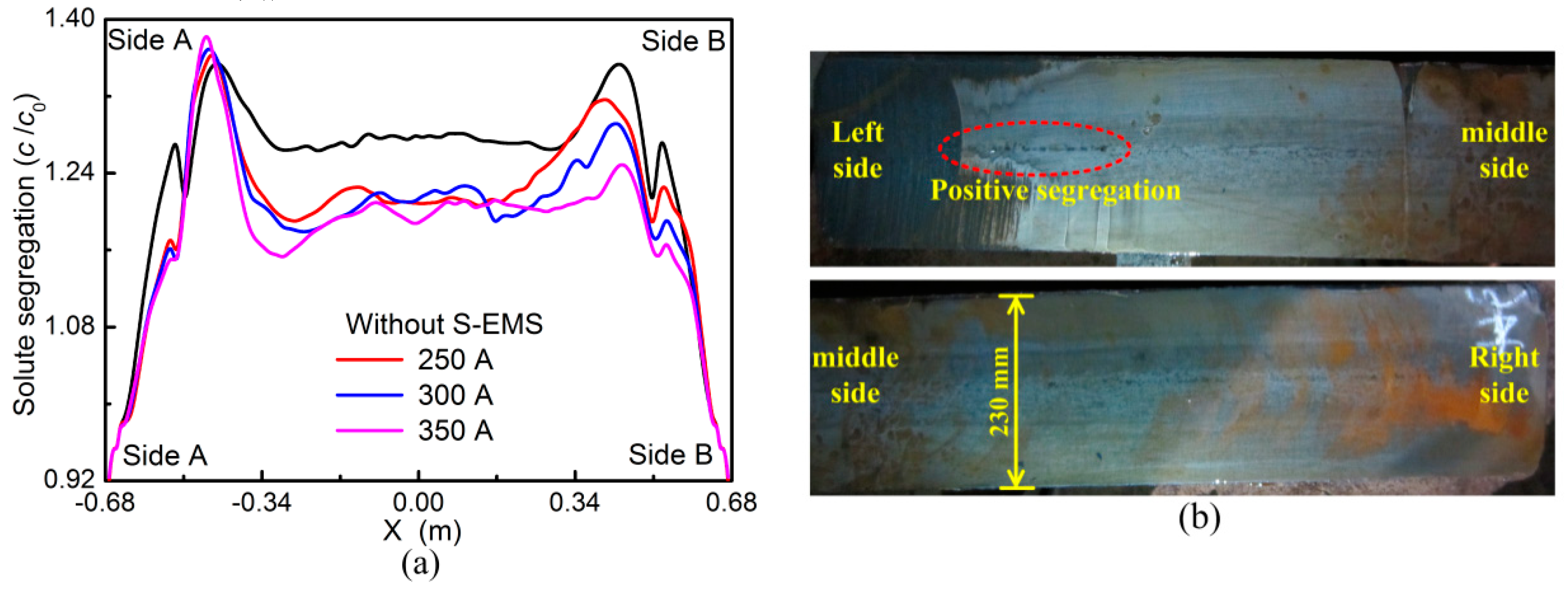
3.1. Model Validation

In order to validate the electromagnetic model, the calculated magnetic induction intensity in the middle part of two stirring rolls is compared with the measured values, as shown in Figure 3. The calculated magnetic induction intensity agrees well with the measured, as the S-EMS frequency is set at 4 Hz. With the increase in current intensity, both the calculated and measured magnetic induction intensities rise simultaneously, although there are some deviations existed between them.
Figure 4 shows the predicted and the measured temperature on the strand surface along the casting direction. It is obtained that both data show a good agreement, although the predicted temperature is a little higher than the measured. This may have been due to the process of spraying water vapor on the slab surface, which possibly affected the temperature measurement.

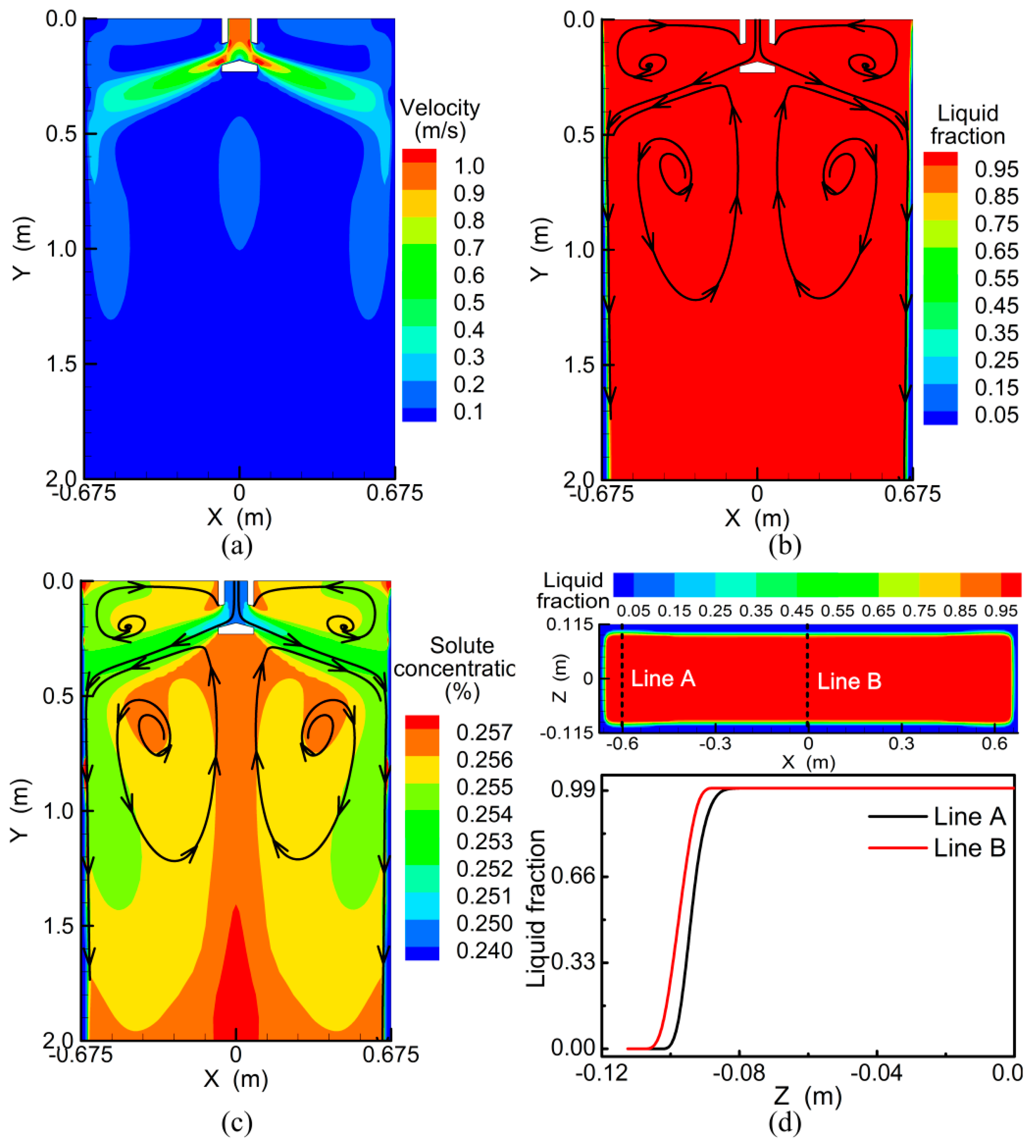
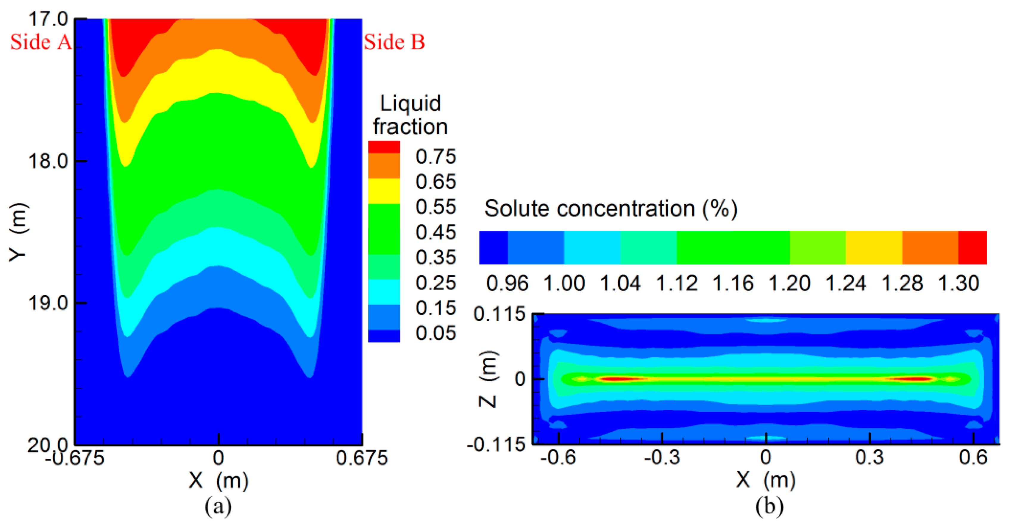
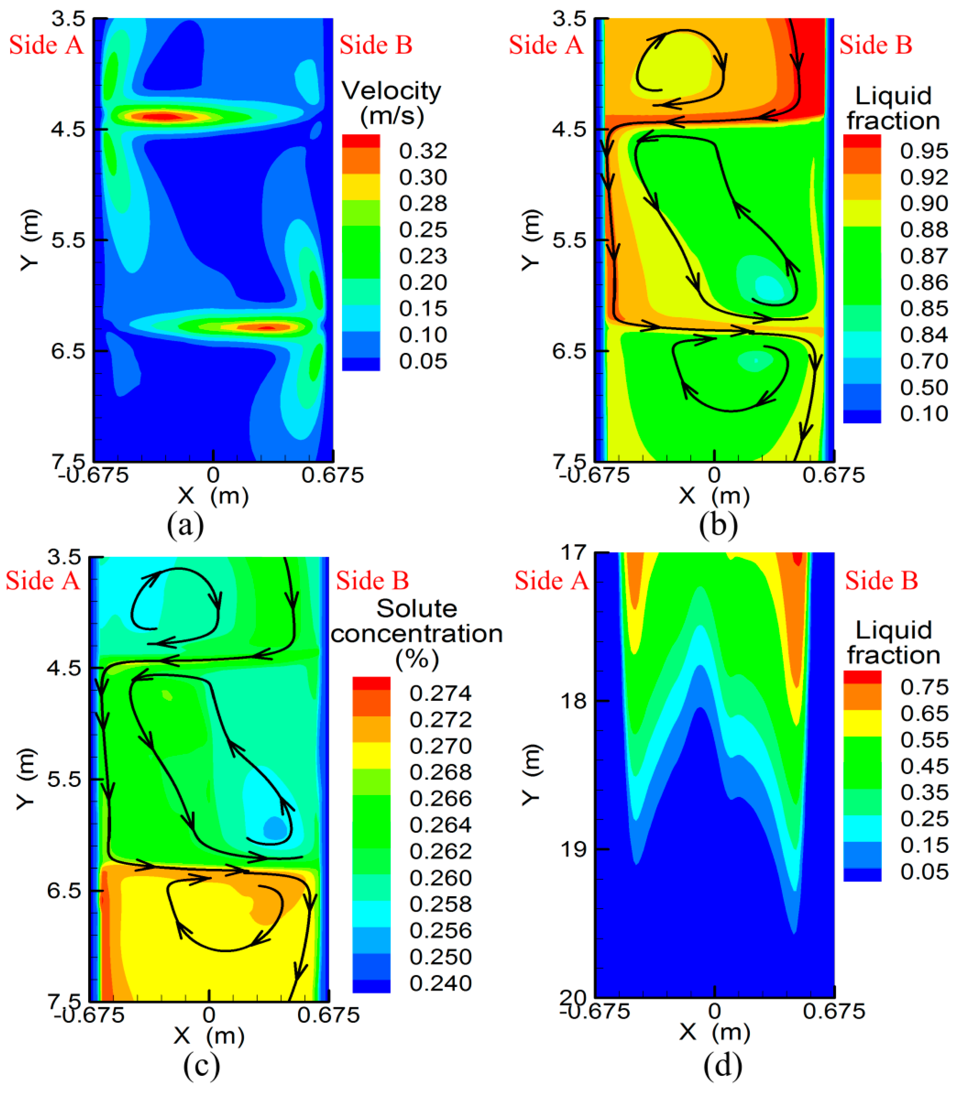
3.2. Transport Behavior without S-EMS

In the slab continuous casting process, liquid steel flows to the copper mold zone at high speed and washes the strand narrow face, as shown in Figure 5a,b. One part of liquid steel returns upward and impinges steel-slag interface directly. Then it moves to the outside of submerged entry nozzle (SEN) and turns back to the mainstream flow. The other part of liquid steel moves downward along the solidification front and a pair of vertexes are formed in the lower part of the mold zone. As the latent heat is extracted from the copper mold, solid shell grows gradually and liquid temperature decreases with fluid flow. In the meantime, the negative solute element is rejected from the solid phase and transports with liquid flow, as shown in Figure 5c. It should be noted that the fluid flow pattern in the liquid pool obviously affects the solid shell distribution in the cross section, shown in Figure 5d. It can be seen that the solid shell in the strand cross section is not uniform. The solid shell thickness near strand narrow face is 12.5 mm, while that in the middle part is 17 mm. That is because the liquid steel from SEN contains a large amount of superheat which it injects to the strand narrow face, which retards solid shell growth. In the later solidification stage, the unevenness of solid shell may also influence the solidification end profile.
Figure 6a shows the liquid fraction distribution in the longitudinal section near the strand solidification end. It is obtained that the liquid fraction distribution near the strand narrow face is clearly larger than that in the middle part. With the solidification proceeding, the solidification ends near the 1/4 width of slab are postponed. The solidification end position near strand narrow face is 19.52 m from the meniscus, while that in the middle part is 19.03 m. The liquid solidification end profile also affects solute distribution in the strand cross section, as shown in Figure 6b. The solute element is concentrated in the strand inner part and the centerline segregation near the narrow face is obviously serious, which reaches about 1.31. That is because the liquid steel near the strand narrow face is the last part to solidify and the rejected solute has more time to concentrate. From the simulation above, it is concluded that fluid flow pattern from the SEN can obviously affect the solidification end profile and solute distribution in the strand.

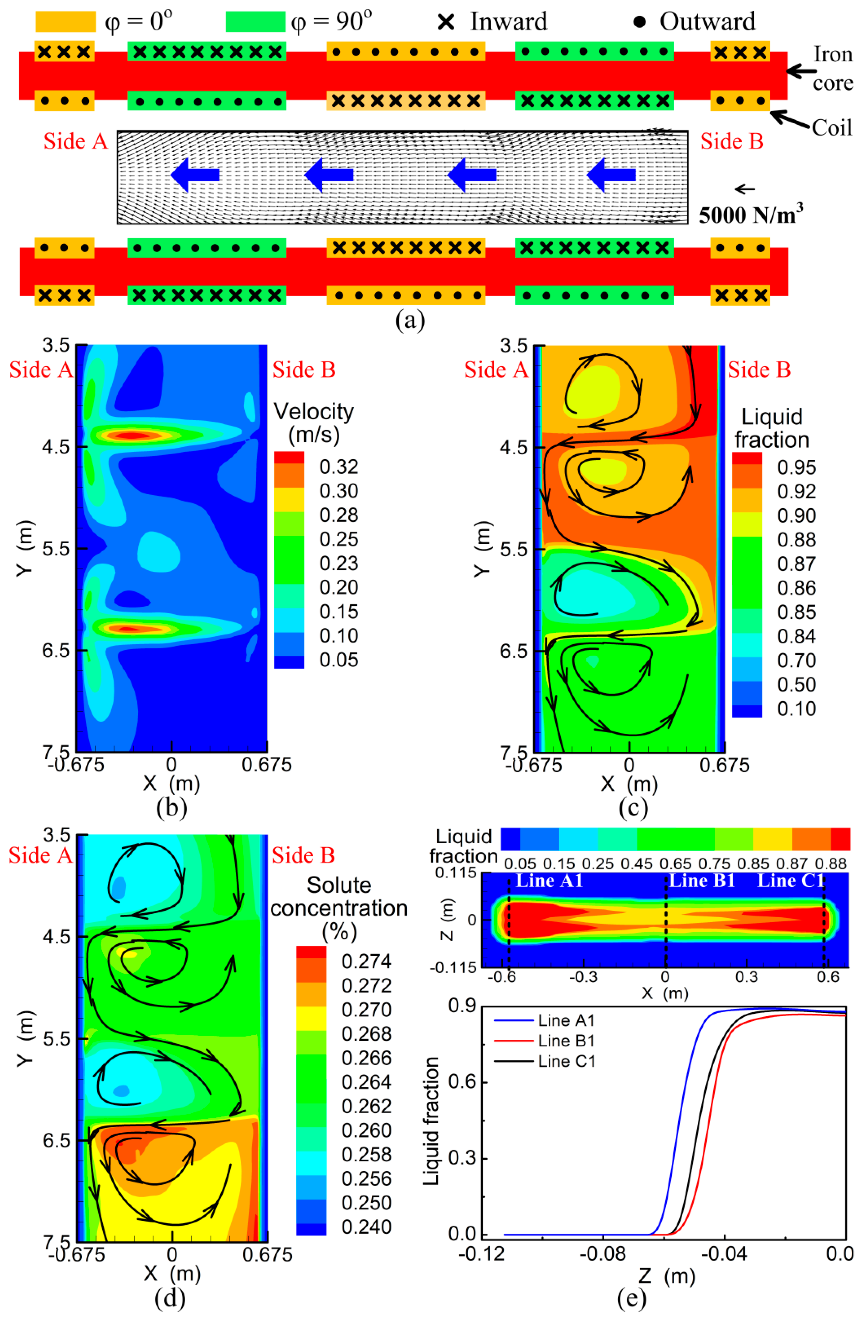
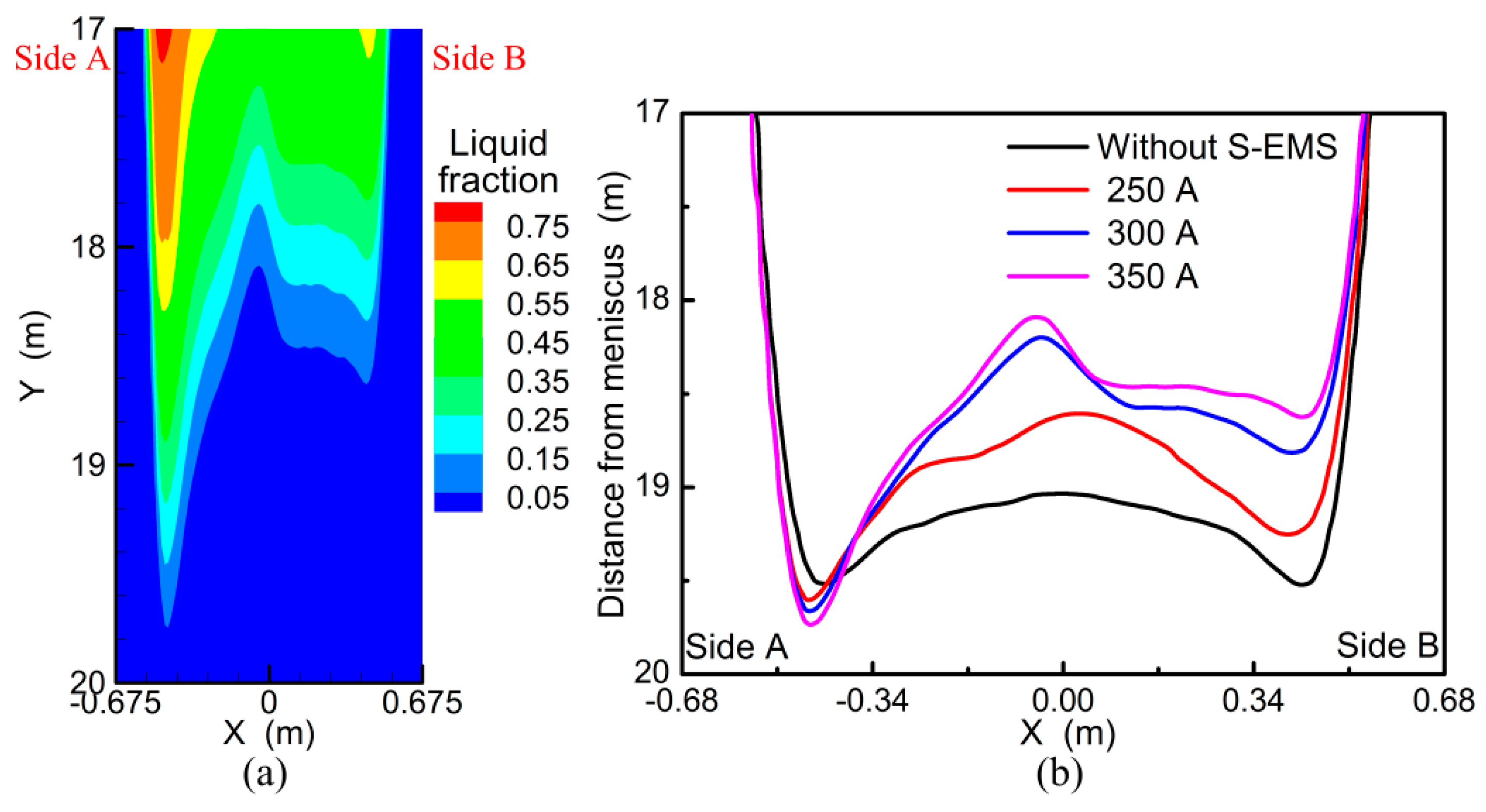
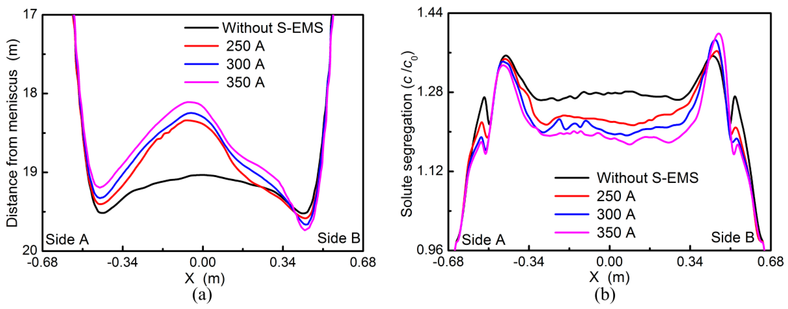
3.3. Linear Stirring in the Same Direction

In the slab continuous casting process, the S-EMS stirrer is widely installed in the secondary cooling zone and the electric current with different phases (φ = 0° or 90°) is applied in the coils, as shown in Figure 7a. With the current set at 350 A and 6 Hz, the linear electromagnetic force is induced in the strand and liquid steel is forced to move linearly in the horizontal direction, as shown in Figure 7b,c. In the upper stirring zone, the liquid steel is driven to move from side B to side A and washes strand narrow face. One part of liquid steel moves upward and a vertex is formed above the upper stirring roll. The other part of liquid steel moves downward and turns back to side B. Because the stirring directions of two rollers are the same, the returned liquid steel moves to side A again and a pair of vertexes forms. The liquid steel reaches the maximum stirring velocity near the side A, which is about 0.32 m/s. As liquid steel is forced to move around, the heat transfer behavior is enhanced and the liquid fraction decreases gradually. In the meanwhile, the negative solute element is rejected from solid and transports with fluid flow, as shown in Figure 7d. In order to understand the solidification behavior more clearly, the liquid fraction along the line A1, B1, and C1 are illustrated in Figure 7e. It is obtained that the solid shell thickness near the side A is 55 mm, while that in the side B and middle part are 61 and 62.5 mm respectively. That is because the stirring stream with higher temperature impinges the narrow face and the solid shell growth near the side A is retarded, which influences the solidification behavior in the later stage.
Figure 8a,b show solidification behavior in the longitudinal section with current intensity set at 350 A and the solidification end profile along the transverse section with different current intensities. In the conventional continuous casting process, the solidification end near the strand narrow face is postponed. With the S-EMS applied, the solidification end position near the side B moves backward, while that near the side A shifts forward. With the current intensity increase, the unevenness of solidification end profile becomes more serious. There are two reasons. One is that the stirring flow impinges the strand narrow face and the solid shell growth near the side A slows down. The other is that the impinged liquid steel in the lower stirring zone penetrates deep downward, which contains a large amount of latent heat. In the later solidification stage, the solid shell near the side A grows slowly and the liquid steel is the last to solidify. It is obtained that the forced flow in the liquid pool can obviously affect the heat transfer behavior, which clearly influences the solidification end profile.
Along with the solidification end being affected by stirring flow, the centerline solute segregation is also influenced, as shown in Figure 9a. Because the solidification end near the side B moves backward, the solute segregation is reduced. However, the centerline segregation near the side A is deteriorated. That is because the solidification end near side A is postponed and the solute element has more time to transport, resulting in the solute element enrichment. In the plant trials, it is also found that strand centerline segregation near the left side of the slab is serious with current intensity set at 350 A, indicated in Figure 9b. Therefore, the centerline segregation in the slab cannot be fully improved by the linear stirring in the same direction, which is not appropriated for slab continuous casting process.

3.4. Linear Stirring in the Opposite Direction

Aside from the linear stirring in the same direction applied in the slab continuous casting process, liquid steel can be forced to move in the opposite direction, as shown in Figure 10a,b. In the upper stirring zone, liquid steel is forced to move from the side B to side A and washes slab narrow face. Some liquid steel flows downward to the lower stirring zone and moves from side A to side B. Then the liquid steel reaches the maximum velocity near side B and penetrates deep down along the solidification front. With fluid flow in the liquid pool, the heat transfer behavior is enhanced and the temperature decreases continuously. In the same time, the solute element is rejected from solid and transports with fluid flow, as shown in Figure 10c. In the later cooling stage, the solidification end in the middle part moves backward, while that near side B moves forward, illustrated in Figure 10d. That is because the moving downward liquid steel in the lower stirring zone contains much latent heat and the solidification behavior near the side B slows down.
Figure 11a,b illustrate the effect of stirring intensity on solidification end profile and centerline solute segregation. With no S-EMS applied, the solidification end positions near the side A and B are almost equal. However, with the current intensity increase, the solidification end near the side B moves forwards, while that near the side A moves backward. That is because the liquid steel with higher temperature is forced to move from the side A to side B in the lower stirring zone and penetrates deep down along the solidification front. As solidification end moves forward, the rejected solute element has more time to transport and the centerline segregation near the side B is deteriorated, especially with higher current intensity. It is obtained that the solidification end profile and centerline solute segregation redistribution is obviously influenced by the stirring flow, especially in the lower stirring zone.

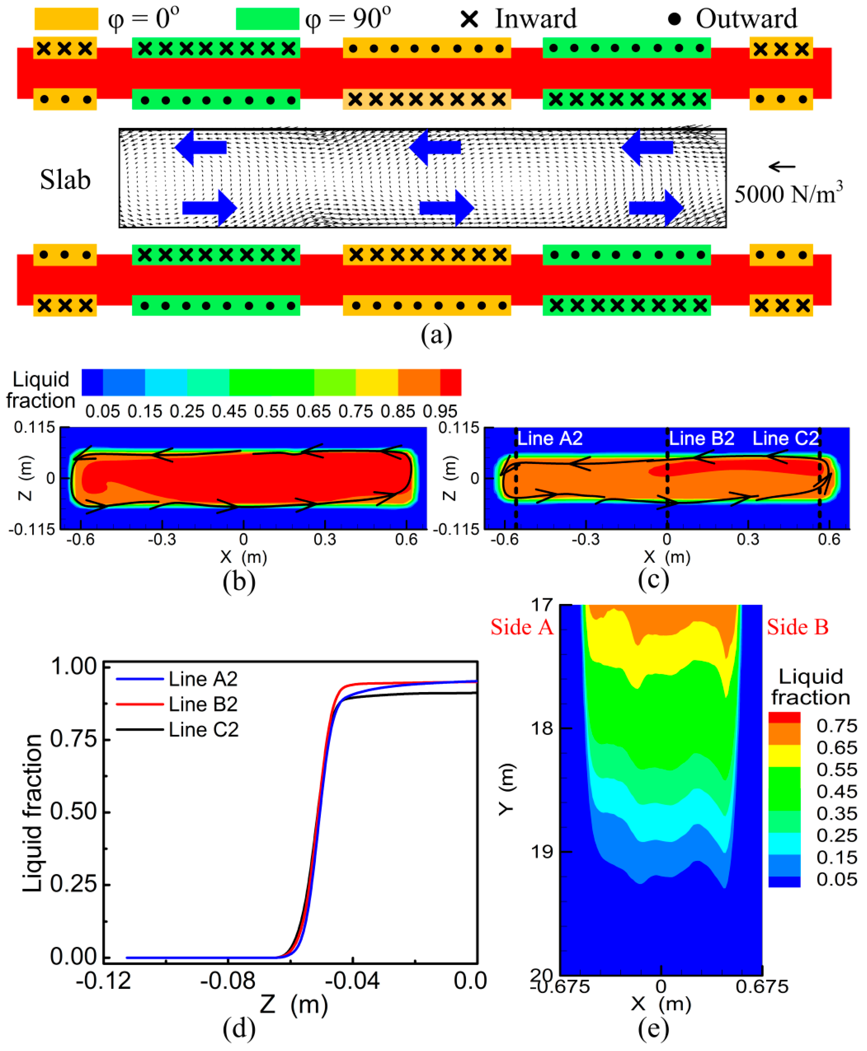
3.5. Effect of the Rotational Stirring Mode

From the numerical simulation in Section 3.3 and Section 3.4, it is obtained that linear stirring flow impinges the slab narrow face and solidification end profile is modified. Besides the linear stirring modes are applied in the casting process, the rotational stirring mode can be generated by adjusting the current phase in the coil, as shown in Figure 12a. In this part, the influence of rotational flow on the transport behavior in slab continuous casting is investigated. Figure 12b,c show the liquid fraction and fluid flow in the strand cross section at 4.4 and 6.3 m from the meniscus. It can be seen that liquid steel moves in the anticlockwise direction and the solidification front is washed. Because the induced electromagnetic force is not uniform, the liquid fraction in the strand inner part is unevenly distributed. In order to have a better understanding of solidification behavior in the stirring zone, the liquid fraction along the line A2, B2, and C2 are shown in Figure 12d. It is obtained that the solid shell thicknesses are almost equal, although the center liquid fraction in the line B2 and C2 are slightly larger than that of line A2. As the distance from meniscus increases, the strand solidifies gradually and liquid fraction decreases, shown in Figure 12e. With the rotational stirring mode used, the solidification end position along the strand width direction is almost simultaneous.
Figure 13a illustrates the effect of current intensity on the solidification end profile and centerline solute segregation with the rotational stirring mode. In the normal continuous casting process, the strand in the middle part solidified earlier, while that near the side A and B solidifies later. With the rotational stirring mode used, the solidification end position near the narrow face moves backward and that in the middle part moves forward, resulting in the solidification end evenly distributed. As the current intensity increases, the heat transfer behavior in the liquid pool is enhanced and the evenness of solidification end is improved. The variation of solidification end profile also influences centerline segregation distribution, as shown in Figure 13b. The centerline segregation near the slab narrow face is reduced as rotational stirring mode is used, especially with higher current intensity. Besides, it is also found that the improvement of solute segregation in the sides A and B are not equal, which is due to the uneven distribution of electromagnetic force induced by S-EMS.
In the present work, the effects of stirring mode and current intensity on solidification end profile and solute segregation are investigated. The lever rule was used in the solute transport model, and the grain movement with fluid flow was not considered. In the future, a multiple solidification model coupling macroscale heat transfer and fluid flow with microscale grain nucleation and growth will be built to investigate the transport phenomena in the slab continuous casting with S-EMS. Besides, some plant trials with rotational stirring mode should be conducted to verified the calculated results.

4. Conclusions

In the current work, the transport behavior in the slab continuous casting with S-EMS is numerically investigated. The main results are summarized as follows:
  • Because liquid steel from SEN injects to strand narrow face directly, the solidification end near the 1/4 width of slab is postponed and solute element is enriched.
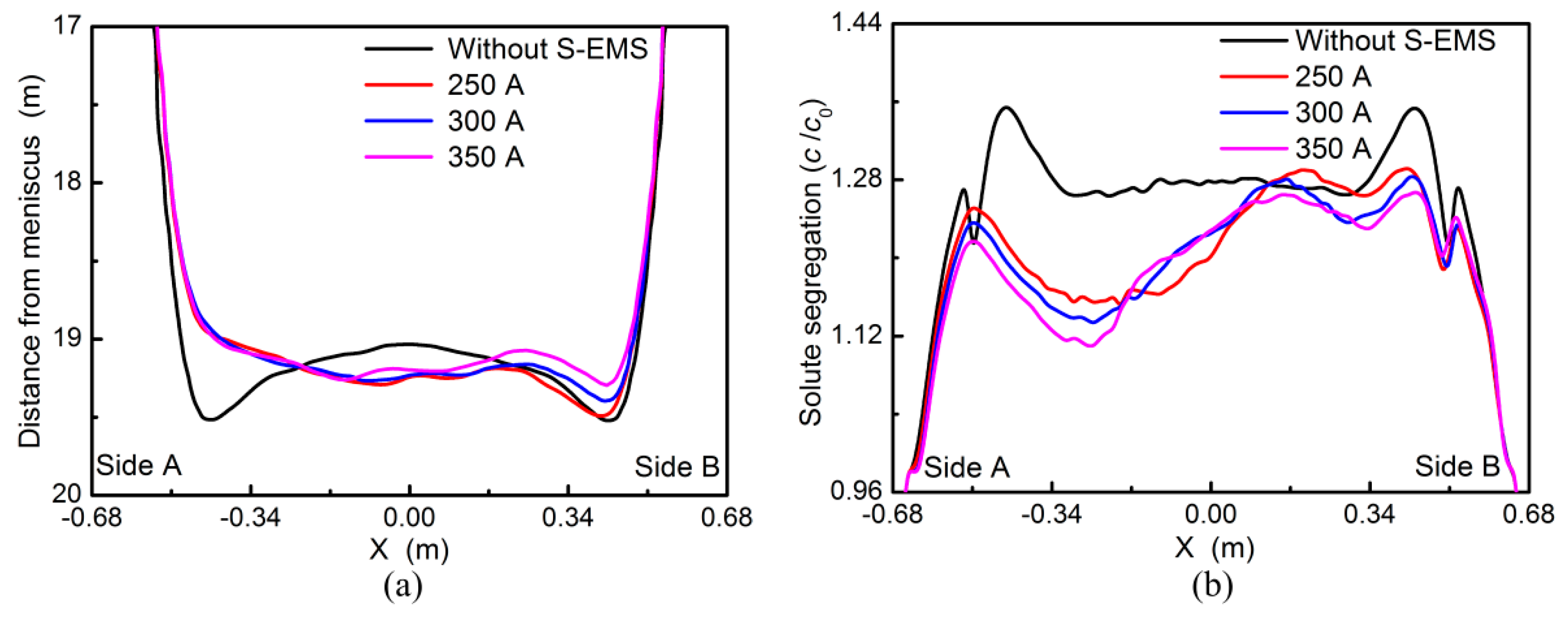
  • With the linear stirring in the same direction applied, liquid flows from side B to side A and penetrates deep down along the solidification front. The solidification end near side A moves backward and solute segregation is deteriorated, which becomes more serious with higher current intensity.
  • As the linear stirring in opposite direction is used, the solidification end near the side A moves forward, while that near the side B moves backward. Moreover, it is obtained that the centerline segregation near the side B is reduced, but that near the side A is deteriorated.
  • With the rotational stirring mode applied, liquid steel is driven to move around in the cross section and solid shell grows uniformly. As the current intensity increases, liquid steel solidifies simultaneously in the later stage and the centerline segregation is reduced.

Author Contributions

Conceptualization, D.J., M.Z. and L.Z.; methodology, M.Z.; software, L.Z.; validation, D.J. and L.Z.; formal analysis, D.J.; investigation, D.J.; resources, D.J. and M.Z.; data curation, D.J.; writing—original draft preparation, D.J.; writing—review and editing, D.J. and L.Z.; visualization, D.J.; supervision, L.Z.

Funding

This research was founded by the National Key Research and Development Program of China (Grant Number 2017YFB0304001), China Postdoctoral Science Foundation (Grant Number 2018M641194), and the Fundamental Research Funds for the Central Universities (Grant Number FRF-TP-18-098A1).

Conflicts of Interest

The authors declare no conflict of interest.

References

  1. Singh, K.; Basu, B. Mathematical modeling of macrosegregation of iron carbon binary alloy: role of double diffusive convection. Metall. Mater. Trans. B 1995, 26, 1069–1081. [Google Scholar] [CrossRef]
  2. Ayata, K.; Mori, H.; Taniguchi, K.; Matsuda, H. Low superheat teeming with electromagnetic stirring. ISIJ Int. 1995, 35, 680–685. [Google Scholar] [CrossRef]
  3. Jiang, D.; Wang, W.; Luo, S.; Ji, C.; Zhu, M. Numerical simulation of slab centerline segregation with mechanical reduction during continuous casting process. Int. J. Heat Mass Transfer 2018, 122, 315–323. [Google Scholar] [CrossRef]
  4. Liu, H.; Xu, M.; Qiu, S.; Zhang, H. Numerical simulation of fluid flow in a round bloom mold with in-mold rotary electromagnetic stirring. Metall. Mater. Trans. B 2012, 43, 1657–1675. [Google Scholar] [CrossRef]
  5. Huang, J.; Wang, E.G.; He, J. Numerical simulation of linear electromagnetic stirring in secondary cooling region of slab caster. J. Iron Steel Res. Int. 2003, 10, 16–21. [Google Scholar]
  6. Song, X.; Cheng, S.; Cheng, Z. Mathematical modelling of billet casting with secondary cooling zone electromagnetic stirrer. Ironmaking Steelmaking 2013, 40, 189–198. [Google Scholar] [CrossRef]
  7. Ren, B.Z.; Chen, D.F.; Wang, H.D.; Long, M.J. Numerical analysis of coupled turbulent flow and macroscopic solidification in a round bloom continuous casting mold with electromagnetic stirring. Steel Res. Int. 2015, 86, 1104–1115. [Google Scholar] [CrossRef]
  8. Maurya, A.; Jha, P.K. Influence of electromagnetic stirrer position on fluid flow and solidification in continuous casting mold. Appl. Math. Model. 2017, 48, 736–748. [Google Scholar] [CrossRef]
  9. Sun, H.B.; Zhang, J.Q. Study on the macrosegregation behavior for the bloom continuous casting: Model development and validation. Metall. Mater. Trans. B 2014, 45, 1133–1149. [Google Scholar] [CrossRef]
  10. Jiang, D.B.; Zhu, M.Y. Solidification structure and macrosegregation of billet continuous casting process with dual electromagnetic stirrings in mold and final stage of solidification: A numerical study. Metall. Mater. Trans. B 2016, 47, 3446–3458. [Google Scholar] [CrossRef]
  11. Medina, M.; Terrail, Y.; Durand, F.; Fautrelle, Y. Channel segregation during solidification and the effects of an alternating traveling magnetic field. Metall. Mater. Trans. B 2004, 35, 743–754. [Google Scholar] [CrossRef]
  12. Bridge, M.R.; Rogers, G.D. Structural effects and band segregation formation during the electromagnetic stirring of strand-cast steel. Metall. Mater. Trans. B 1984, 15, 581–589. [Google Scholar] [CrossRef]
  13. Ayata, K.; Mori, T.; Fujimoto, T.; Ohnishi, T.; Wakasugi, I. Improvement of macrosegregation in continuously cast bloom and billet by electromagnetic stirring. ISIJ Int. 1984, 24, 931–939. [Google Scholar] [CrossRef]
  14. Oh, K.S.; Chang, Y.W. Macrosegregation behavior in continuously cast high carbon steel blooms and billets at the final stage of solidification in combination stirring. ISIJ Int. 1995, 35, 866–875. [Google Scholar] [CrossRef]
  15. Yang, B.; Deng, A.; Li, Y.; Xu, X.; Wang, E. Numerical simulation of flow and solidification in continuous casting process with mold electromagnetic stirring. J. Iron Steel Res. Int. 2019, 26, 219–229. [Google Scholar] [CrossRef]
  16. Yu, H.Q.; Zhu, M.Y. Influence of electromagnetic stirring on transport phenomena in round billet continuous casting mould and macrostructure of high carbon steel billet. Ironmaking Steelmaking 2012, 39, 574–584. [Google Scholar] [CrossRef]
  17. Jiang, D.; Zhu, M. Flow and solidification in billet continuous casting machine with dual electromagnetic stirrings of mold and the final solidification. Steel Res. Int. 2015, 86, 993–1003. [Google Scholar] [CrossRef]
  18. Poole, G.M.; El-Kaddah, N. An improved model for the flow in an electromagnetically stirred melt during solidification. Metall. Mater. Trans. B 2013, 44, 1531–1540. [Google Scholar] [CrossRef]
  19. Savage, J.; Pritchard, W.H. The problem of rupture of the billet in the continuous casting of steel. J. Iron Steel Inst. 1954, 178, 269–277. [Google Scholar]
  20. Nozaki, T.; Matsuno, J.; Murata, K.; Ooi, H.; Kodama, M. Secondary cooling pattern for the prevention of surface cracks of continuous casting slab. Tetsu-to-Hagané 1976, 62, 1503–1512. [Google Scholar] [CrossRef]
  21. Dong, Q.P.; Zhang, J.M.; Qian, L.; Yin, Y.B. Three-dimensional numerical modeling of macrosegregation in continuously cast billets. Metals 2017, 7, 209. [Google Scholar] [CrossRef]
Figure 1. Schematic diagram of secondary electromagnetic stirring (S-EMS) in the continuous casting slab.
Metals 09 00452 g001
Figure 2. Etched macrostructure of slab.
Metals 09 00452 g002
Figure 3. Magnetic induction intensity of S-EMS with different current intensities.
Metals 09 00452 g003
Figure 4. Slab surface temperature along the casting direction.
Metals 09 00452 g004
Figure 5. Fluid flow (a), liquid fraction (b), and solute concentration distribution (c) in the mold zone, and the liquid fraction at the mold exit (d).
Metals 09 00452 g005
Figure 6. Liquid fraction in the strand longitudinal section (a) and solute distribution in the cross section (b).
Metals 09 00452 g006
Figure 7. Electromagnetic force distribution and the applied current (a), fluid flow (b), liquid fraction (c), and solute concentration (d) in the stirring zone, and the liquid fraction distribution about 7 m from meniscus (e).
Metals 09 00452 g007
Figure 8. Liquid fraction in the longitudinal section with current intensity set at 350 A (a), and solidification end profile along the transverse direction (b).
Metals 09 00452 g008
Figure 9. Solute segregation distribution along the transverse direction (a) and the etched macrostructure of slab with current set at 350 A (b).
Metals 09 00452 g009
Figure 10. Fluid flow (a), liquid fraction (b), and solute concentration (c) in the stirring zone, liquid fraction distribution near the solidification end (d).
Metals 09 00452 g010
Figure 11. Solidification end profile (a) and centerline segregation (b) along the transverse direction.
Metals 09 00452 g011
Figure 12. Electromagnetic force distribution and applied current (a), fluid flow and solidification at 4.4 (b) and 6.3 m (c) from meniscus, liquid fraction distribution along the transverse direction (d) and in the longitudinal section (e).
Metals 09 00452 g012
Figure 13. Solidification end profile (a) and centerline solute segregation (b) along the transverse direction with different current intensities.
Metals 09 00452 g013
Table 1. Physical properties and process parameters used in the numerical simulation.
ItemValue (unit)
Slab dimensions230 × 1350 (mm)
Steel density (ρ)7000 (kg·m−3)
Liquid viscosity (μl)0.006 (kg·m−1·s−1)
Thermal conductivity (k)30 (W·m−1·K−1)
Specific heat (Cp)690 (J·kg−1·K−1)
Latent heat (L)27,5000 (J·kg−1)
Casting speed (vc)0.9 (m·min−1)
Casting temperature (T0)1798 (K)
Solute content (c0)0.25 (%)
Partition coefficient (kp)0.34
Liquid and solid diffusion coefficient (Dl and Ds)2 × 10⁻⁹ (m2·s−1)

