Article

Investigation of Bipolar Plate Forming with Various Die Configurations by Magnetic Pulse Method

1
National Center for Materials Service Safety, University of Science and Technology Beijing, Beijing 100083, China
2
School of Mechanical Engineering and Automation, Beihang University, Beijing 100191, China
3
Beijing Advanced Innovation Center for Biomedical Engineering, Beihang University, Beijing 100191, China
*
Author to whom correspondence should be addressed.
Metals 2019, 9(4), 453; https://doi.org/10.3390/met9040453
Submission received: 22 March 2019 / Revised: 12 April 2019 / Accepted: 15 April 2019 / Published: 17 April 2019
(This article belongs to the Special Issue Forming and Heat Treatment of Modern Metallic Materials)

Abstract

:
Bipolar plates are a major part of fuel cells, which are a clean and recyclable energy source. This study was carried out with two dies for a bipolar plate forming investigation with the magnetic pulse method: a bipolar plate die and a 10-channel die. With the bipolar plate die, the forming of bipolar plates with a Cu110 sheet and a Grade 2 Ti sheet indicated that the bipolar plate die needed optimization for a full replication. The obtained maximum average depth percentage was 86% for a Cu110 sheet, while it was 54% for a Grade 2 Ti sheet in this study. A further increase of the depth percentage is possible but requires a much higher capacitor bank energy. The increase of the capacitor bank energy would result in severe tearing, while the depth percentage increase was little. The primary current and flyer velocity were measured at various capacitor bank energies. With the 10-channel die, the die parameters’ effect on metal sheet forming was investigated with a Cu110 sheet and an SS201 sheet. The draft angle had a significant effect on the replication of the die surface. The full replication was achieved for channels with proper parameters with both a Cu110 sheet and an SS201 sheet. Therefore, the bipolar plate die could be optimized based on the 10-channel die results.

1. Introduction

Due to the current problems, such as global warming and harmful pollutants, people have begun to search for other energy sources that are different from natural gas, oil, and coal [1,2]. Fuel cells, which are a clean and recyclable energy source [3]. Among various fuel cells, the polymer electrolyte membrane fuel cell (PEMFC), the operation temperature of which is 30–100 °C, is a better choice for city buses and power systems of portable electronic devices. However, up to now, fuel cells had limited applications. The high cost is a big issue, which limits its wide use (4–10 times more expensive than internal combustion engines). The majority of the cost of fuel cells is used in materials and manufacturing. The fabrication of the frames of the fuel cell, which are called bipolar plates, takes up 70–80% of the fuel cell weight and 40–50% of the fuel cell cost [4]. Much work still needs to be done in order to make fuel cells low-cost and suitable for civil use.
Bipolar plates, which connect fuel cells together and is usually known as a “stack” (operates at around 0.7 V), with micro-channels on the surfaces feed hydrogen to the anode and oxygen to the cathode [4]. Therefore, bipolar plates must have a good conductivity. In addition, a good resistance to corrosion is also necessary. Until now, the materials which were used to fabricate bipolar plates were electrographite, coated metal sheets, uncoated metal sheets, and graphite polymer composites [5]. The mechanical property of electrographite is worse than that of metal sheets, although it has a good conductivity. Graphite polymer composites are usually more expensive than metal sheets. A coated metal sheet is also limited by the coating materials. Recently, stainless steel without coating has been considered as a potential candidate material for bipolar plate fabrication due to its good mechanical properties and stability [6]. Other than that, titanium was also studied as the bipolar plate for its excellent corrosion resistance and high strength to weight ratio [7]. Due to the good formability of copper, it was also selected as one of the potential bipolar plate materials [8].
The metal sheet is expected to be as thin as possible in order to decrease the weight of the bipolar plates, but the precondition is that enough strength and enough depth of the micro-channels should be guaranteed. Based on this consideration, a good formability is needed. Recently, the forming of metal sheets with rubber pads was studied by various researchers in order to increase the formability and to avoid the wrinkle and springback issues [7,9,10]. However, the forming process with rubber pads requires a high loading. It is applicable for a small area forming. Magnetic pulse forming has many advantages [11,12,13], such as increasing the forming limit of materials and decreasing wrinkling and distortion [14]. The difference between traditional forming and magnetic pulse forming is shown in Figure 1. With magnetic pulse forming, only one side of the die is needed, while for the tradition forming method, both dies are required. Therefore, magnetic pulse is a promising method for the forming of bipolar plates. In this paper, through the study of metal forming with the magnetic pulse method, the feasibility of the current bipolar plate die would be investigated. Through the study of metal forming with a 10-channel die, the possible optimization of the current bipolar plate die would be suggested for the magnetic pulse method.

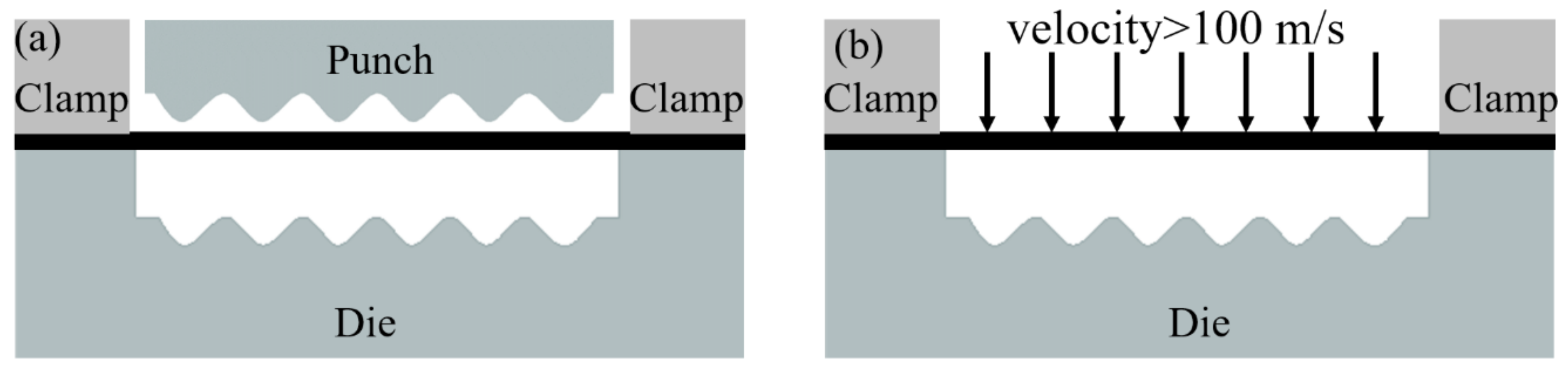
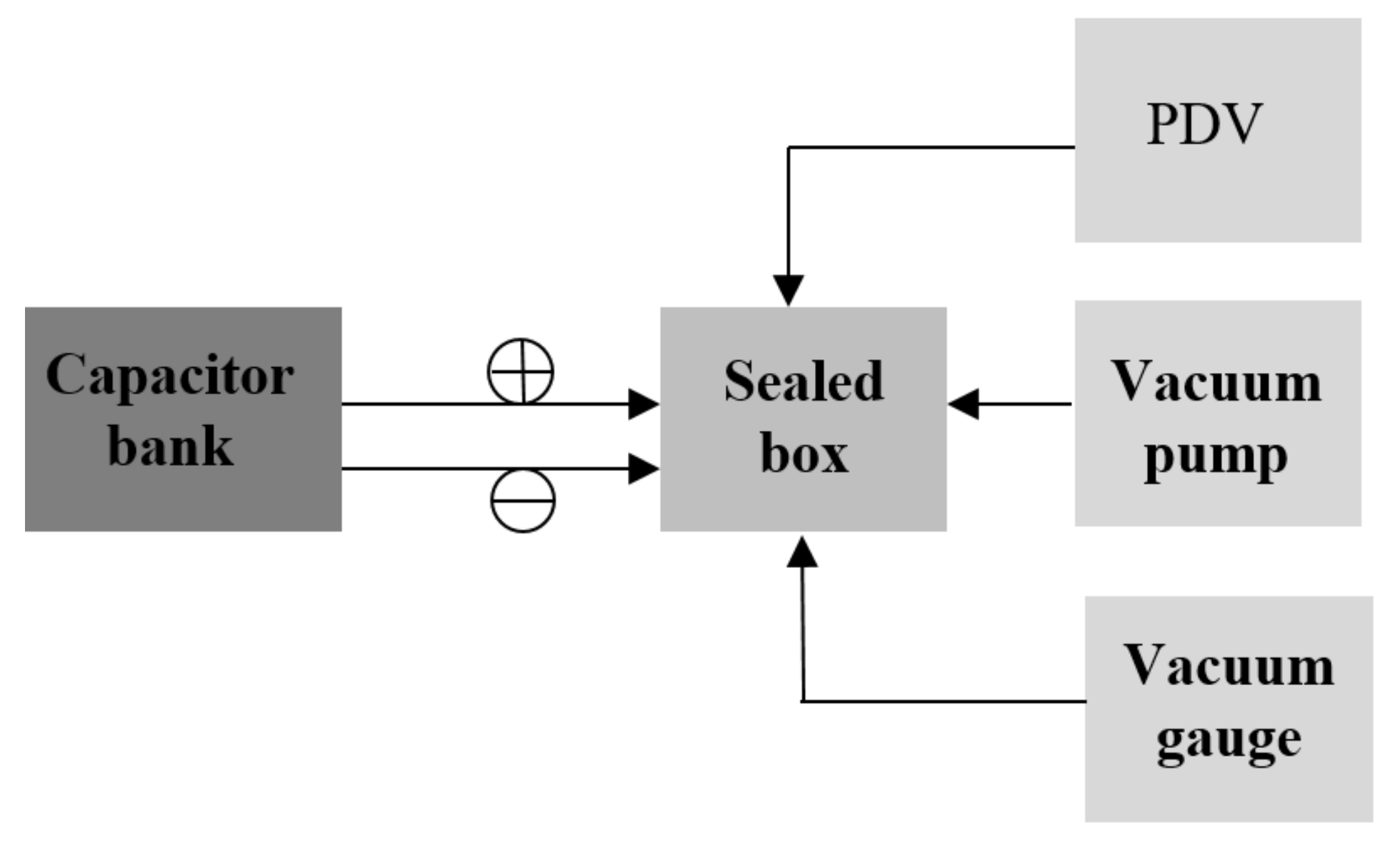
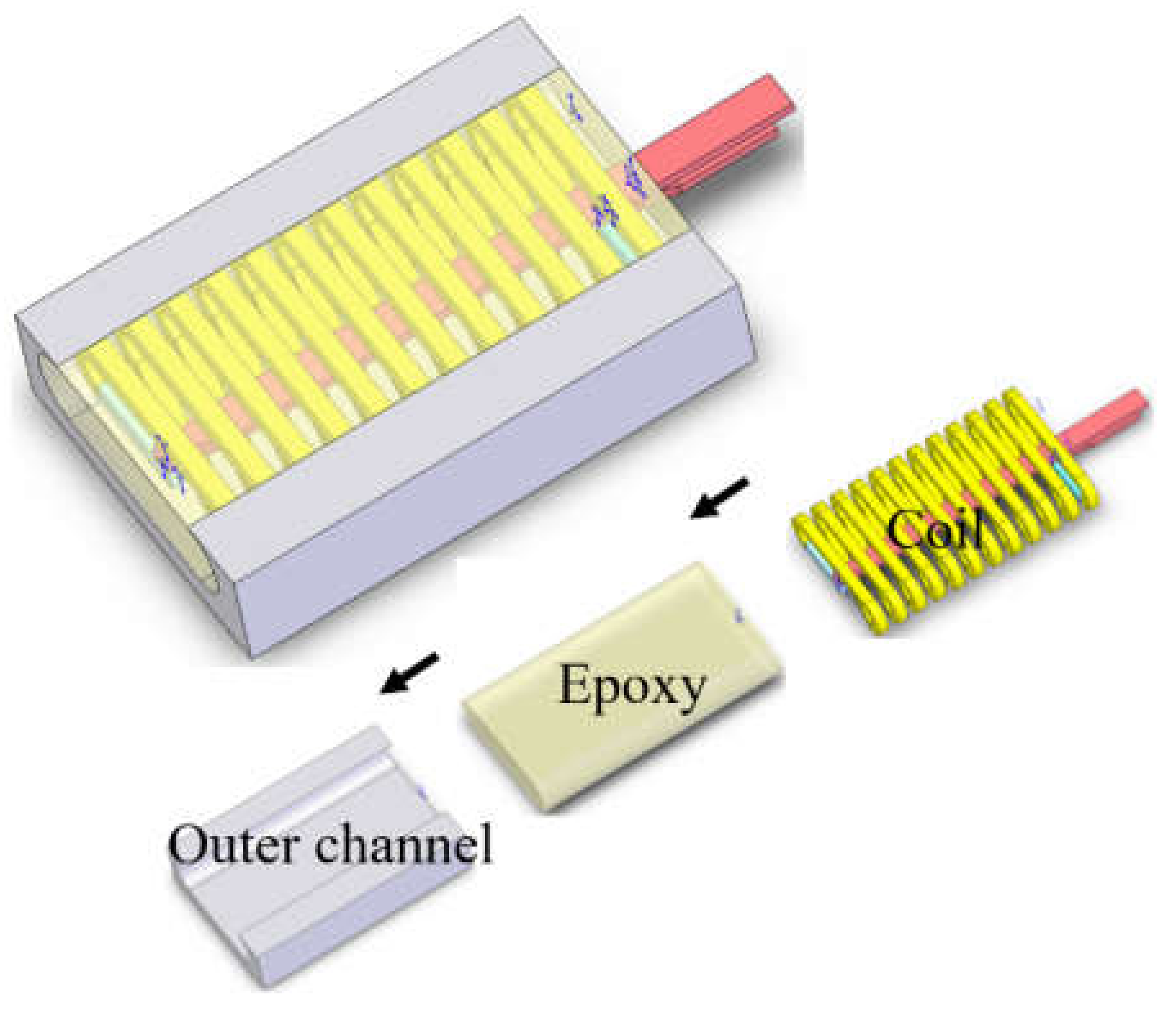
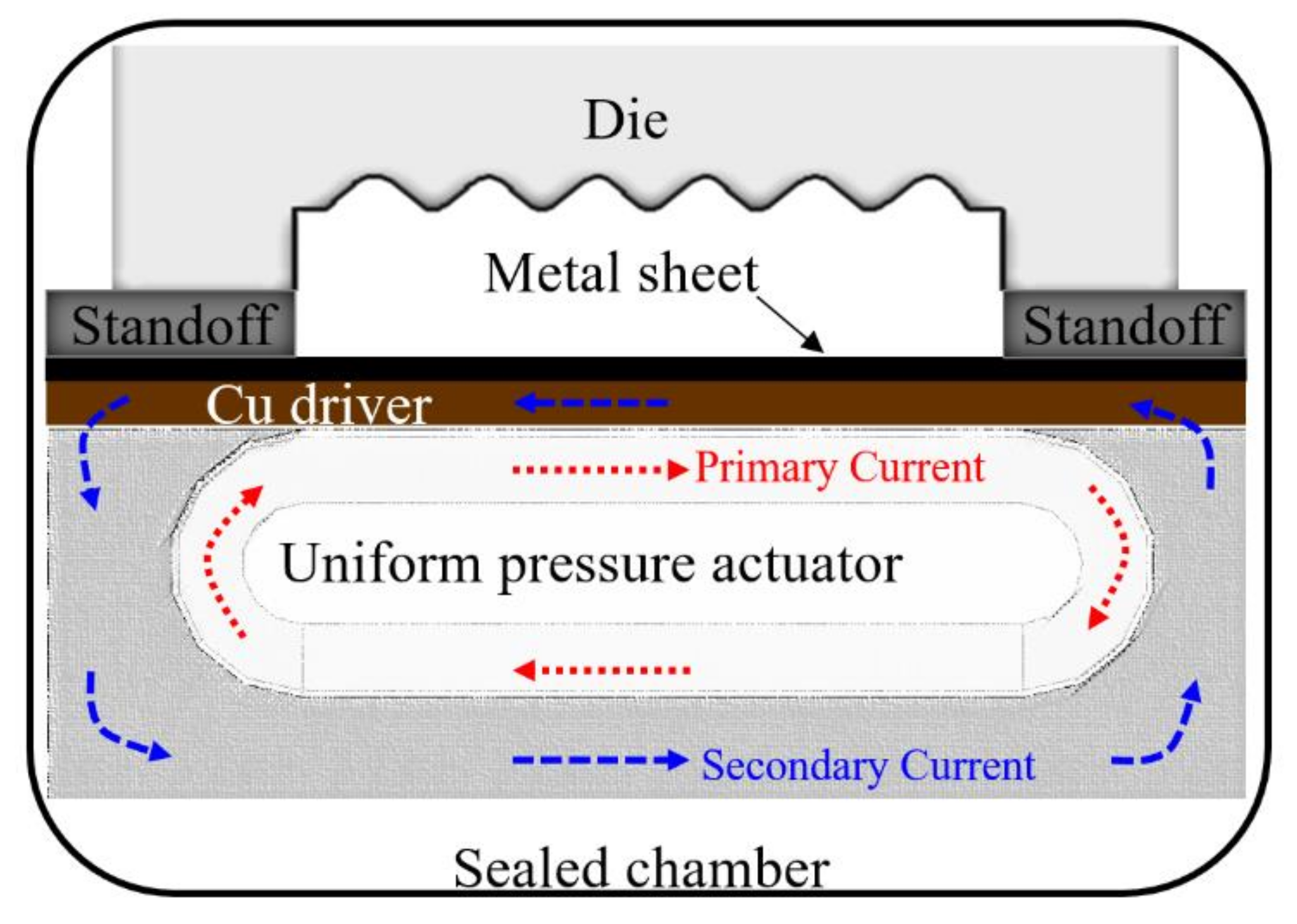
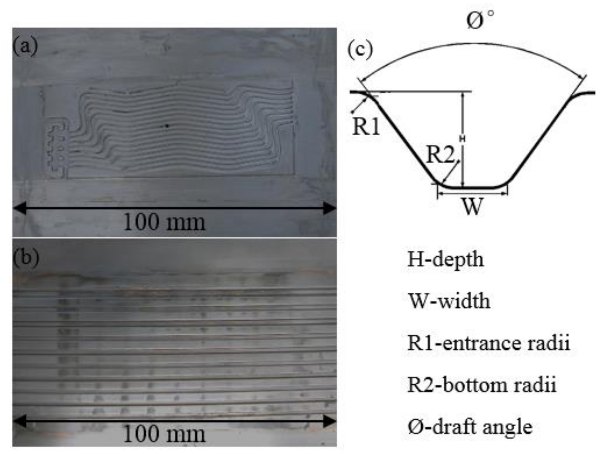
2. Experimental Setup

The experimental system for the forming of bipolar plates using the magnetic pulse forming method is shown in Figure 2. A capacitor bank is the energy source for the experiment. Its output energy is adjustable between 0 and 16 kJ. Photon Doppler Velocimetry (PDV) measures the velocity of metal sheets during the forming process. The experiment was carried out within the sealed chamber. A vacuum pump (Trivac D76A, Leybold, Export, PA, USA) keeps the sealed chamber around 100 torr for a good formability. If the sealed chamber is full of air due to the high velocity collision between the metal sheet and the die, air bubble forms on the metal sheet. The vacuum gauge (varian Convec torr gauge) detects the vacuum condition of the sealed chamber.
As shown in Figure 3, the uniform pressure actuator was made of an inner solenoid coil, epoxy, and an outer coil. The gap between the solenoid coil and outer coil was filled with epoxy. The inner solenoid coil was connected with the capacitor bank to form the closed current loop. The contact between the metal sheet and the outer coil formed another current loop. When the capacitor bank was on, the primary current ran through the inner solenoid coil. Simultaneously, the outer coil and the metal sheet carried the induced secondary current, which ran in the opposite direction of the primary current. Therefore, due to the repel force between the inner solenoid coil of the uniform pressure actuator and metal sheet, the metal sheet accelerated upward into the die while the uniform pressure actuator was fixed in place. The repel force was related not only to the capacitor bank energy but also to the conductivity of metal sheets. The better the conductivity was, the higher the induced secondary current was. For low conductivity materials, like titanium, a copper sheet was used as a driver, as shown in Figure 4. The work sheet moved together with the driver into the die. A standoff was inserted between the metal sheet and the die to provide distance for the metal sheet to accelerate up to a certain velocity.
The experimental setup was put in a vacuum chamber, where the experiments were carried out. Without a vacuum, the compressed air between the work sheet and the die due to the high velocity movement of the work sheet is a huge resistance for the work sheet moving into the die. The vacuum chamber was made of steel plates. The top of the chamber was sealed by a piece of deformable plastic sheet. The deformable sheet was clamped by an Enerpac hydraulic RC256 press (Enerpac, Milwaukee, WI, USA). A high clamping force reduced the contact air resistance between the work sheet and the outer channel, which composed the secondary current loop. In this experiment, two kinds of dies with various channel shapes and dimensions were used: a bipolar plate die and a 10-channel die, as shown in Figure 5. The dimension of a channel was described by depth, width, entrance radii, bottom radii, and draft angle. The bipolar plate die had 17 channels with the same dimension, which was provided by a commercial company. The 10-channel die had 10 channels with various dimensions. The dimensions of the dies are shown in Table 1. Three kinds of materials were studied in this experiment: Cu110, Grade 2 Ti, and SS201 with thicknesses of 0.15 mm, 0.08 mm, and 0.10 mm, respectively. The same Cu110 was also used as the driver for Grade 2 Ti and SS201. The nominal composition of materials are listed in Table 2. The yield strength of the as-received Cu110, Grade 2 Ti, and SS201 were 69 MPa, 276 MPa, and 360 MPa at the annealed condition.

3. Results and Discussion

3.1. Experimental Results with the Bipolar Plate Die

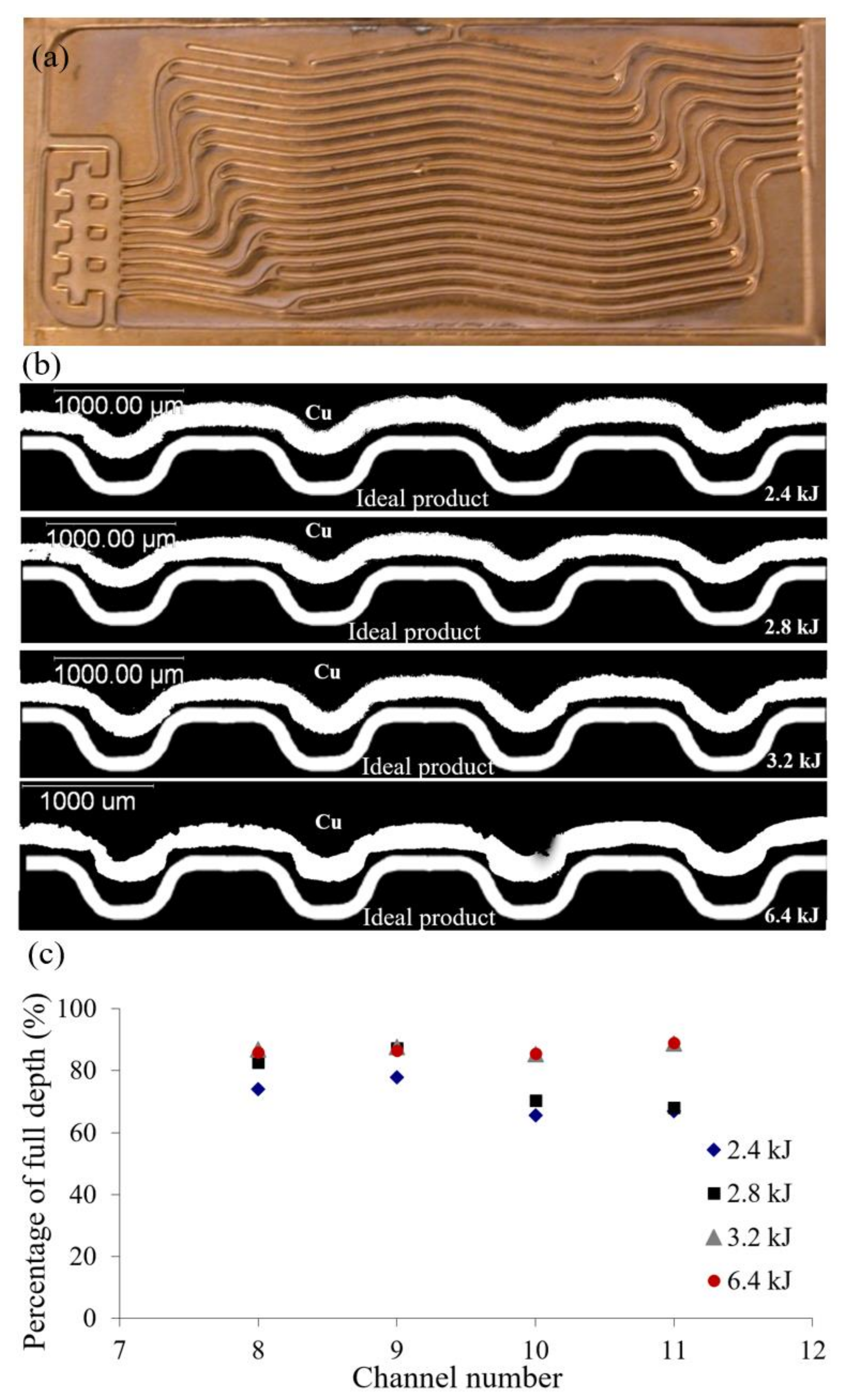
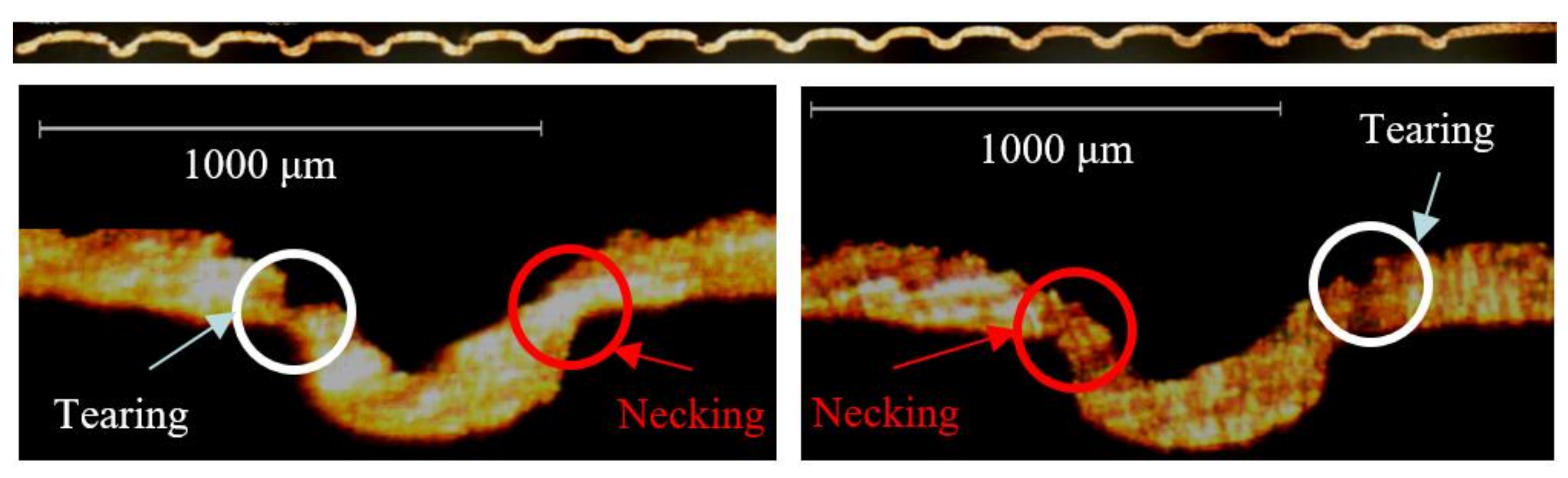
3.1.1. Cu110 as the Workpiece

With Cu110 as the workpiece, the experiments were conducted at the following capacitor bank energy levels: 2.4 kJ, 2.8 kJ, 3.2 kJ, and 6.4 kJ. Figure 6a shows one of the formed bipolar plates with Cu110 (6.4 kJ). It deformed into the shape of the bipolar plate die (Figure 5a) with the magnetic pulse forming method. The channels are clearly shown. The cross section of the formed bipolar plate was prepared for the dimensional measurement of the channels. The cross section of the middle four channels for each bipolar plate is shown in Figure 6b. The ideal product was the full replication of the die. The comparison between the formed bipolar plate and the ideal product shows that the bipolar plate was not fully formed at the capacitor bank energy applied. With a capacitor bank energy increase, the channel depth increased. The necking phenomenon at the channel entrance started to appear at a capacitor bank energy of 3.2 kJ. The tearing and necking phenomenon of the Cu110 bipolar plate at a capacitor bank energy of 6.4 kJ is shown in Figure 7. The depth measurement of the middle four channels for each bipolar is plotted in Figure 6c. The highest percentage of full depth was 89% at a 6.4-kJ capacitor bank energy. The average percentages of full depth for each bipolar plate were 71%, 75%, 84%, and 86% at capacitor bank energies of 2.4 kJ, 2.8 kJ, 3.2 kJ, and 6.4 kJ, respectively. The corresponding standard deviations were 6%, 7%, 5%, and 2%. It turned out that the increase of the capacitor bank energy did not result in an increase of the maximum depth percentage when it was over 84%. However, the increase of the capacitor bank energy resulted in the tearing at the entrance of the die channel.

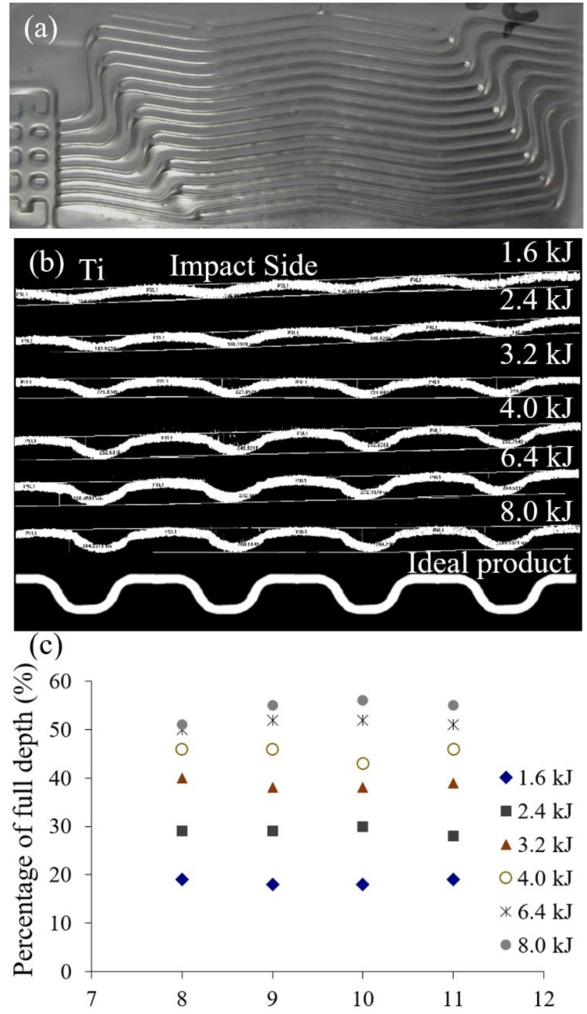
3.1.2. Titanium as the Workpiece

Due to the low conductivity of titanium, copper sheets were used as the driver to have a higher secondary current. Thus, the flyer velocity would be higher at the collision point. With titanium metal sheets, the bipolar forming experiments were conducted with the following capacitor bank energy: 1.6 kJ, 2.4 kJ, 3.2 kJ, 4.0 kJ, 6.4 kJ, and 8.0 kJ. Figure 8a shows the formed Ti bipolar plate. Similar to the Cu110 bipolar plate, it deformed into the shape of the bipolar plate die. The cross section of the deformed Grade 2 Ti sheets is shown in Figure 8b. The depth of the channels increased with the capacitor bank energy. The depth percentage of the middle four channels are plotted in Figure 8c. The channel depth was uniform between the channels. The average depth percentages of each deformed Ti sheet at capacitor bank energies of 1.6 kJ, 2.4 kJ, 3.2 kJ, 4.0 kJ, 6.4 kJ, and 8.0 kJ were 19%, 29%, 39%, 45%, 51%, and 54%, respectively. Compared with the depth percentage of the deformed Cu110 sheet, at the same capacitor bank energy, the deformed Ti sheet had less depth percentage. Even at the highest energy (8.0 kJ), the depth was less than 60% of the full depth of the die.

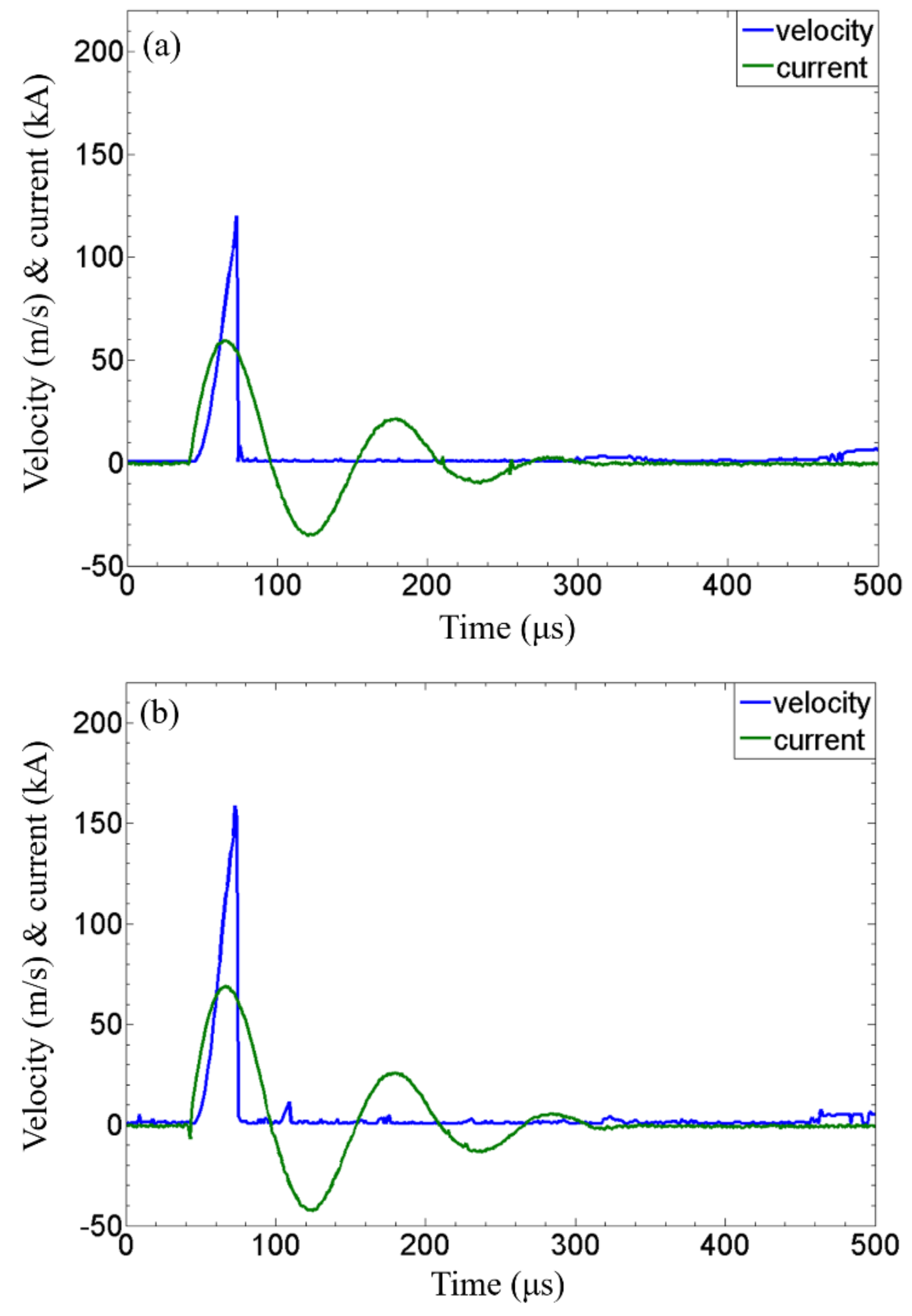
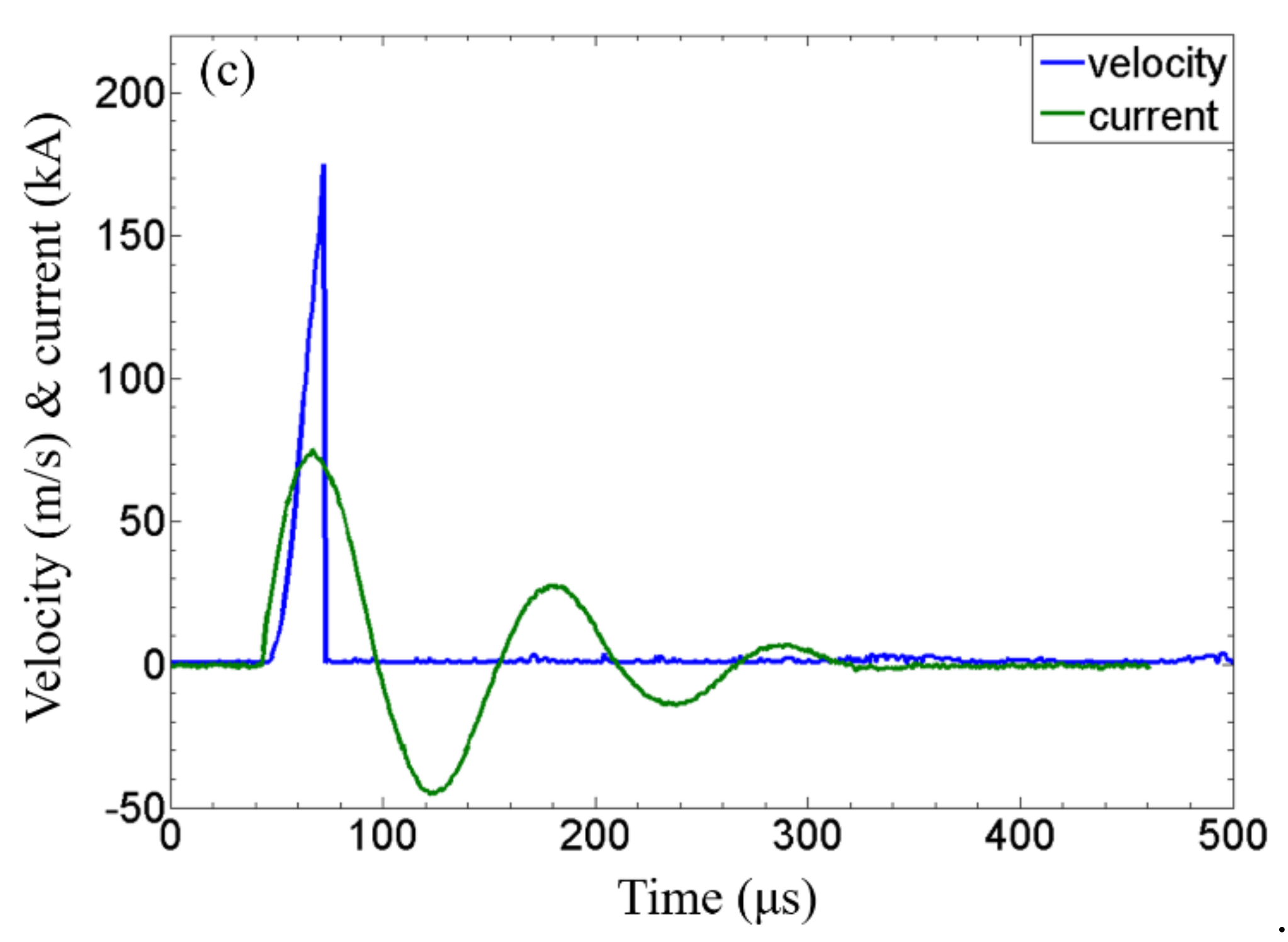
3.1.3. Primary Current and Flyer Velocity Measurement

The measured primary current and flyer velocity for Cu110 sheets at capacitor bank energies of 1.6 kJ, 2.4 kJ, and 2.8 kJ are displayed in Figure 9. The maximum primary currents at capacitor bank energies of 1.6 kJ, 2.4 kJ, and 2.8 kJ were 58 kA, 69 kA, and 75 kA, respectively. The corresponding flyer velocities were 120 m/s, 159 m/s, and 175 m/s, respectively. Both the primary current and flyer velocity increased with the capacitor bank energy. The increase of the flyer velocity resulted in a higher impact pressure between the flyer and the target. Therefore, the channel depth of formed bipolar plate increased with the capacitor bank energy. For Ti bipolar plate forming with Cu110 as the driver, the primary currents of the uniform pressure actuator are shown in Figure 10a at capacitor bank energies of 1.6 kJ, 3.2 kJ, 4.0 kJ, 4.8 kJ, 5.6 kJ, 6.4 kJ, and 8.0 kJ and were 58 kA, 77 kA, 84 kA, 91 kA, 100 kA, 105 kA, and 118 kA, respectively. The primary current for Cu110 bipolar plate forming at a capacitor bank energy of 1.6 kJ was 58 kA, the same as Ti bipolar plate forming with Cu110 as the driver, as shown in Figure 9a. The same primary current for Cu110 bipolar plate forming and Ti bipolar plate forming with Cu110 as the driver indicated that the Ti flyer did not have an effect on the primary current. The measured Ti flyer velocity at a capacitor bank energy of 4.0 kJ is plotted in Figure 10b. The corresponding primary current is also shown. The maximum Ti flyer velocity was 125 m/s, which was lower than the Cu flyer velocity at a capacitor bank energy of 2.8 kJ. The addition of titanium actually increased the weight of the “flying part” (driver and the flyer). The higher weight resulted in a lower acceleration and, thus, a lower flyer velocity upon collision.

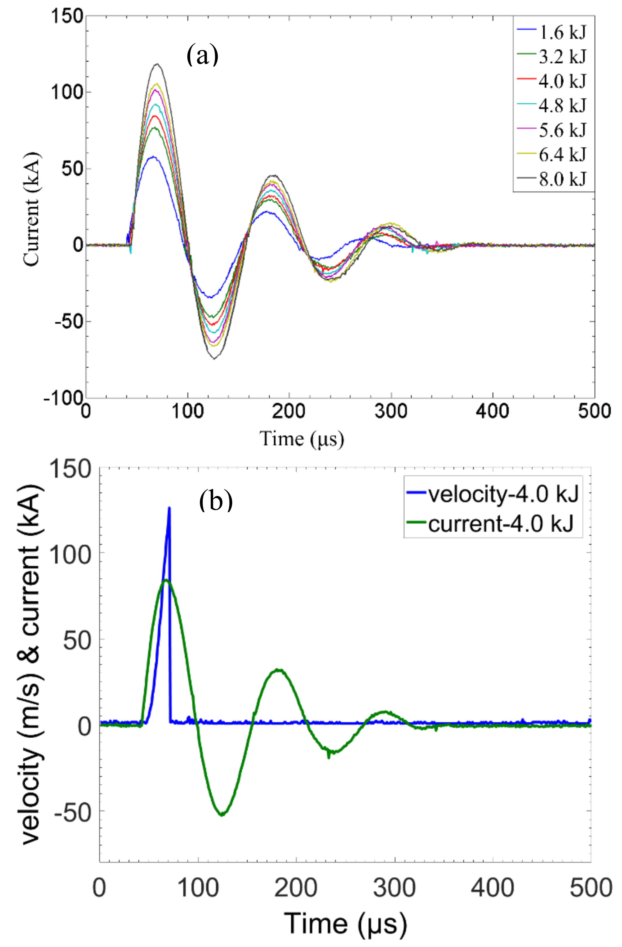
3.2 Experimental Results with 10-Channel Die

All the channels have the same dimension for the bipolar plate die. In addition, with the current bipolar plate die, the die channels could not be fully replicated, as stated above. In order to study the die dimension effect on the depth percentage, the 10-channel die was designed with various channel dimensions. The experiments were conducted at a capacitor bank energy of 4.8 kJ with a 2 mm standoff. The deformed Cu110 and SS201 sheets are presented in Figure 11. The cross section of 10 channels of the deformed Cu110 sheet clearly displayed the dimension variation between the channels. Channels with a depth of 0.381 mm were fully formed with Cu110 for all the draft angles. Channel 2 with a depth of 0.762 mm and a draft angle of 0° sheared during forming. The enlarged image of channel 4 shows the thickness variation of the Cu110 sheet along the channel. The thinning in the thickness direction occurred at the bottom of the channel and the entrance of the channel. No cracking was observed for channel 4. Necking and thinning was not observed from channel 6, channel 8, and channel 10 with Cu110. The variation of the channels indicated that the draft angle of 45° was proper for a channel with a depth of 0.762 mm and a width of 1 mm.
As shown in Figure 11b, the formability of SS201 was less than that of Cu110. Channels with a depth of 0.762 mm were not fully formed for all the draft angles. The shearing of channel 1 was not caused by the experiment. It was due to the preparation of the sample. Due to less deformation than Cu110, the thinning phenomenon in the thickness direction along the channel was not observed. Figure 11c shows that, for SS201 sheets, the depth percentage was higher for channels with a die depth of 0.381 mm than that of 0.762 mm with the same draft angle. For a die depth of 0.381 mm, the depth percentage was above 90%, while for a die depth of 0.762 mm, the die depth was between 50% and 70%. For an SS201 sheet, the full replication of a die channel was achieved with a die depth of 0.381 mm, a width of 1 mm, and a draft angle of 90°.

3.3. Discussion

In summary, magnetic pulse forming is a robust forming method. By adjusting the experimental parameters, the micrometer scale channels could be formed. However, different materials have varied formability. For each type of material, the experimental parameters are unique for the full deformation before tearing. With magnetic pulse forming, only a one-side die is needed. The issues for traditional forming, like die tolerance, do not exist. From this point, the magnetic pulse forming reduces the cost.
Cu110, Grade 2 Ti, and SS201 were used as the material to fabricate bipolar plates using magnetic pulse forming. Due to Cu110 having a better formability than Ti and SS201 at the same capacitor bank energy, deeper channels formed with Cu110 sheets. At a capacitor bank energy of 8 kJ, the depth percentage was less than 60%. With Cu110 at a capacitor bank energy of 3.2 kJ, the depth percentage was over 80%. With a 10-channel die, Cu110 was fully formed for each channel, while the depth of the formed channels with SS201 varied with channel depth and draft angle.
Through the study of metal sheets with Cu110 and Ti, it turned out that the depth percentage was uniform between channels with a low depth percentage and a high depth percentage. With Ti metal sheets, the uniform deformation between channels at a low capacitor bank energy (1.6 kJ) revealed that the electromagnetic pressure is uniform. The variation of the electromagnetic pressure over the whole deformation area became more and more obvious with the increase of the capacitor bank energy. For Cu110 sheets, the increase of the capacitor bank energy did not cause the increase in the maximum depth percentage but caused the uniform deformation of the Cu110 sheet between channels. The increase of the capacitor bank energy from 3.2 kJ to 6.4 kJ resulted in an increase of the average depth from 84% to 86%. However, the severe tearing and necking phenomenon appeared due to the severe plastic deformation under a higher impact pressure [15].
The draft angle played a significant role in the metal sheet forming process. When the draft angle was 0° for a die channel depth of 0.762 mm, the metal sheet sheared. When the draft angle was 90° for die channel depth of 0.762 mm, the Cu110 sheet was fully deformed. With an SS201 sheet, the depth percentage increased with an increasing draft angle for both 0.381-mm and 0.762-mm-deep die channels. Along the channel, the necking phenomenon appeared at the entrance and at the bottom of the channel, which indicated that the severe plastic deformation occurred in those areas. Both the primary current and the flyer velocity increased with the capacitor bank energy. The primary current was not affected by adding Ti to the “flying part”. However, the flyer velocity decreased a lot, which may have been caused by the weight add to the “flying part”.

4. Conclusions

In this study, the feasibility of the current bipolar plate die and bipolar plate forming with magnetic pulse forming for various metal sheets was investigated. The main conclusions are listed below.
1.
With the current bipolar plate die, the maximum average channel depth with a Cu110 sheet was 86% at a capacitor bank energy 6.4 kJ, while the maximum average channel depth with a Ti sheet was 54% at a capacitor bank energy of 8.0 kJ.
2.
For a Cu110 sheet, the increase of the capacitor bank energy from 3.2 kJ to 6.4 kJ resulted in the increase of the average depth percentage from 84% to 86%, but severe tearing and necking appeared at 6.4 kJ. For a Ti sheet, the increase of the capacitor bank energy from 6.4 kJ to 8.0 kJ caused the increase of the average depth percentage from 51% to 54%. For both metal sheets, the increase of the channel depth over the current maximum values would require much higher capacitor bank energies. Therefore, the current bipolar plate die would be optimized for full penetration with the magnetic pulse method.
3.
Both the primary current and flyer velocity increased with the capacitor bank energy. When Cu110 was the driver, the primary current was not affected by the addition of Ti to the “flying part”, but the flyer velocity was reduced due to the weight increase of the “flying part”.
4.
With the 10-channel die, a full penetration was achieved for channels with proper die parameters with both a Cu110 sheet and an SS201 sheet, which provided valuable information for the optimization of the bipolar plate die. The draft angle had a significant effect on the replication of the die surface. For a Cu110 sheet, the minimum draft angle was 23° for a channel with a depth of 0.762 mm and a width of 1 mm. For an SS201 sheet, the full replication was achieved for a channel with a depth of 0.381 mm, a width of 1 mm, and a draft angle of 90°.

Author Contributions

H.W.: experiment, data collection, data analysis, figures, wring-first draft. Y.W.: data interpretation, data analysis, study design, final writing, revision.

Funding

This APC of this work was supported by the Fundamental Research Funds for the Central Universities (Grant No. 06500107).

Acknowledgments

This research was carried out at The Ohio State University, US. The authors want to give Glenn Daehn and Geoff Taber special thanks for the help during the experiments.

Conflicts of Interest

The authors declare no conflict of interest.

References

  1. Momirlan, M.; Veziroglu, T.N. Current status of hydrogen energy. Renew. Sustain. Energy Rev. 2002, 6, 141–179. [Google Scholar] [CrossRef]
  2. Cropper, M.A.J.; Geiger, S.; Jollie, D.M. Fuel cells: A survey of current developments. J. Power Sources 2004, 131, 57–61. [Google Scholar] [CrossRef]
  3. Hermann, A.; Chaudhuri, T.; Spagnol, P. Bipolar plates for PEM fuel cells: A review. Int. J. Hydrogen Energy 2005, 30, 1297–1302. [Google Scholar] [CrossRef]
  4. Bar-On, I.; Kirchain, R.; Roth, R. Technical cost analysis for PEM fuel cells. J. Power Sources 2002, 109, 71–75. [Google Scholar] [CrossRef]
  5. Steele, B.C.H.; Heinzel, A. Materials for fuel-cell technologies. Nature 2001, 414, 345–352. [Google Scholar] [CrossRef] [PubMed]
  6. Jeong, M.G.; Jin, C.K.; Hwang, G.W.; Kang, C.G. Formability evaluation of stainless steel bipolar plate considering draft angle of die and process parameters by rubber forming. Int. J. Precis. Eng. Manuf. 2014, 15, 913–919. [Google Scholar] [CrossRef]
  7. Jin, C.K.; Jeong, M.G.; Kang, C.G. Fabrication of titanium bipolar plates by rubber forming and performance of single cell using TiN-coated titanium bipolar plates. Int. J. Hydrogen Energy 2013, 39, 21480–21488. [Google Scholar] [CrossRef]
  8. Tawfik, H.; Hung, Y.; Mahajan, D. Metal bipolar plates for PEM fuel cell-A review. J. Power Sources 2007, 163, 755–767. [Google Scholar] [CrossRef]
  9. Elyasi, M.; Khatir, F.A.; Hosseinzadeh, M. Manufacturing metallic bipolar plate fuel cells through rubber pad forming process. Int. J. Adv. Manuf. Technol. 2017, 89, 3257–3269. [Google Scholar] [CrossRef]
  10. Elyasi, M.; Ghadikolaee, H.T.; Hosseinzadeh, M. Fabrication of metallic bipolar plates in PEM fuel cell using semi-stamp rubber forming process. Int. J. Adv. Manuf. Technol. 2017, 92, 765–776. [Google Scholar] [CrossRef]
  11. Kamal, M.; Daehn, G.S. A Uniform Pressure Electromagnetic Actuator for Forming Flat Sheets. J. Manuf. Sci. Eng. 2007, 129, 369–379. [Google Scholar] [CrossRef]
  12. Daehn, G. High velocity metal forming. In Metalworking: Sheet Forming; ASM Handbook Volume 14B; ASM International: Materials Park, OH, USA, 2006; pp. 405–418. [Google Scholar]
  13. Balanethiram, V.S.; Hu, X.; Altynova, M.; Daehn, G.S. Hyperplasticity: Enhanced formability at high rates. J. Mater. Process. Technol. 1994, 45, 595–600. [Google Scholar] [CrossRef]
  14. Shang, J.; Daehn, G. Electromagnetically assisted sheet metal stamping. J. Mater. Process. Technol. 2011, 211, 868–874. [Google Scholar] [CrossRef]
  15. Wang, H.; Vivek, A.; Wang, Y.; Viswanathan, G.; Daehn, G. High strain rate embossing with copper plate. Int. J. Mater. Form. 2017, 10, 697–705. [Google Scholar] [CrossRef]
Figure 1. (a) A schematic of the experimental setup of traditional forming and (b) a schematic of the experimental setup of magnetic pulse forming.
Metals 09 00453 g001
Figure 2. The magnetic-pulse-forming system for the forming of bipolar plates: The experimental work was carried on in the sealed box. Photon Doppler Velocimetry (PDV) was used to measure the velocity. The capacitor bank provided the energy.
Metals 09 00453 g002
Figure 3. A three-dimensional model of the uniform pressure actuator.
Metals 09 00453 g003
Figure 4. The experimental setup for bipolar plate forming using the magnetic pulse forming method.
Metals 09 00453 g004
Figure 5. (a) The bipolar plate die, (b) the 10-channel die, and (c) the parameters describing a channel.
Metals 09 00453 g005
Figure 6. (a) The deformed Cu110 sheet with magnetic pulse forming; (b) a cross-sectional profile of the deformed Cu110 sheet at capacitor bank energies of 2.4 kJ, 2.8 kJ, 3.2 kJ, and 6.4 kJ; and (c) the channel depth of the deformed Cu110 sheet at capacitor bank energies of 2.4 kJ, 2.8 kJ, 3.2 kJ, and 6.4 kJ.
Metals 09 00453 g006
Figure 7. The cross section of the deformed Cu110 sheet at a capacitor bank energy of 6.4 kJ.
Metals 09 00453 g007
Figure 8. (a) The deformed Ti sheet with magnetic pulse forming; (b) the cross-sectional profile of the deformed Ti sheet at capacitor bank energies of 1.6 kJ, 2.4 kJ, 3.2 kJ, 4.0 kJ, 6.4 kJ, and 8.0 kJ; and (c) the channel depth of the deformed Ti sheet at capacitor bank energies of 1.6 kJ, 2.4 kJ, 3.2 kJ, 4.0 kJ, 6.4 kJ, and 8.0 kJ.
Metals 09 00453 g008
Figure 9. The primary current of a uniform pressure actuator and the flyer velocity of Cu110 sheets at capacitor bank energies of (a) 1.6 kJ, (b) 2.4 kJ, and (c) 2.8 kJ.
Metals 09 00453 g009aMetals 09 00453 g009b
Figure 10. (a) The primary current for Ti bipolar plate forming with Cu110 as the driver at capacitor bank energies of 1.6 kJ, 3.2 kJ, 4.0 kJ, 4.8 kJ, 5.6 kJ, 6.4 kJ, and 8.0 kJ and (b) the primary current and flyer velocity at a capacitor bank energy of 4.0 kJ for Ti bipolar plate forming with Cu110 as the driver.
Metals 09 00453 g010
Figure 11. Photo and optical microscope images of (a) a deformed copper plate and (b) a deformed SS201 plate and (c) the percentage of full depth for deformed Cu110 and SS201 metal sheets.
Metals 09 00453 g011
Table 1. The dimensions of the bipolar plate die and 10-channel die.
NumberDepth(mm)Width(mm)Entrance RadiiBottom RadiiDraft Angle
17 channels0.3250.80.2°0.2°40°
Channel 10.3811.00.2°0.2°
Channel 20.7621.00.2°0.2°
Channel 30.3811.00.2°0.2°23°
Channel 40.7621.00.2°0.2°23°
Channel 50.3811.00.2°0.2°45°
Channel 60.7621.00.2°0.2°45°
Channel 70.3811.00.2°0.2°68°
Channel 80.7621.00.2°0.2°68°
Channel 90.3811.00.2°0.2°90°
Channel 100.7621.00.2°0.2°90°
Table 2. The nominal composition (wt %) of the materials used in this study.
MaterialCrCuFeMnSiCNiTi
Cu 110-99.9 -----
Grade 2 Ti--0.3----99.2
SS 20116.0–18.0-Balance5.5–7.5<1.0<0.153.5–5.5-

