Article

The Influence of the Post-Weld Heat Treatment on the Microstructure of Inconel 625/Carbon Steel Bimetal Joint Obtained by Explosive Welding

1
Military University of Technology, Faculty of Mechanical Engineering, 2 gen. W. Urbanowicza str., 00-908 Warsaw, Poland
2
Warsaw University of Technology, Faculty of Materials Science and Engineering, 141 Woloska str., 02-507 Warsaw, Poland
*
Author to whom correspondence should be addressed.
Metals 2019, 9(2), 246; https://doi.org/10.3390/met9020246
Submission received: 11 January 2019 / Revised: 10 February 2019 / Accepted: 12 February 2019 / Published: 19 February 2019
(This article belongs to the Special Issue Explosive Welding)

Abstract

:
Inconel 625 and steel P355NH were bonded by explosive welding in this study. Explosively welded bimetal clad-plate was subjected to the two separated post-weld heat treatment processes: stress relief annealing (at 620 °C for 90 min) and normalizing (at 910 °C for 30 min). Effect of heat treatments on the microstructure of the joint has been evaluated using light and scanning electron microscopy, EDS analysis techniques, and microhardness tests, respectively. It has been stated that stress relief annealing leads to partial recrystallization of steel P355NH microstructure in the joint zone. At the same time, normalizing caused not only the recrystallization of both materials, but also the formation of a diffusion zone and precipitates in Inconel 625. The precipitates in Inconel 625 have been identified as two types of carbides: chromium-rich M23C6 and molybdenum-rich M6C. It has been reported that diffusion of alloying elements into steel P355NH takes place along grain boundaries with additional formation of voids. Scanning transmission electron microscope observation of the grain microstructure in the diffusion zone shows that this area consists of equiaxed grains (at the side of Inconel 625 alloy) and columnar grains (at the side of steel P355NH).

Graphical Abstract

1. Introduction

Corrosive wear is a significant problem for the utilization of components of equipment operating in an aggressive environment, such as reactors, tanks, heat exchangers, and pipelines in the chemical industry and geothermal power plants [1,2]. Basically, the alloys which can provide a specified resistant against corrosion in the aggressive environment are expensive. However, there is no need for making the entire component from corrosion resistant material—only its surface, which has direct contact with an aggressive medium. An approach worth considering is the use of relatively inexpensive material (e.g., non-alloy steel) and cladding it with layer of corrosion resistant alloy, such as stainless steel or nickel alloy providing potentiality of operating in the aggressive environment. This solution allows to reduce the material cost of industry equipment significantly depending on used manufacturing technique [3,4,5]. As an example of such bimetal clad plate Inconel/steel system can be given, in which steel is a load-bearing component while Inconel provides resistance to an aggressive environment. This paper investigates steel P355NH cladded with Inconel 625 as bimetallic material of the above type. A pressure vessel steel grade P355NH, weldable constructional steel with fine grain microstructure, is used as material for the manufacture of pressure equipment operating under high temperature (up to 450 °C) [6]. The poor corrosion resistance of this steel limits its applications as a construction material for the equipment working in the aggressive environment significantly. As it was mentioned previously, the potential solution of this problem is to clad steel P355NH with a layer of corrosion resistant material, e.g., Inconel 625, high-temperature creep resistant nickel alloy which is characterized by high resistance to oxidizing and reducing environment as well as pitting and crevice corrosion and it also displays tolerance to a wide range of the operating temperature (from −150 °C to 982 °C) [7]. Materials cladding or modifying their surface layer are widely used technologies in the production of industry equipment and machinery, but not all of this process can provide sufficient properties in terms of the formability of the cladded material [8,9,10]. The technology which allows to produce such bimetal clad-plate and provide both high quality of joint and formability is the explosive welding technique [11,12,13,14]. In this process, the energy released during detonation of the high explosive is used to accelerate one metal plate into another, and as a result, the high velocity collision of metal plates occurs [15,16]. The high energy collision results in bringing the surfaces of the colliding metals close enough to each other to obtain interaction between their atoms and make the formation of a metallic bond between them possible [14,17,18,19,20]. The severe plastic deformation of the materials significantly influences their microstructure and causes strain hardening in the joint zone. Clad-plates manufactured by this method are subjected to further technological processes to form specific equipment components for the industry, e.g. pipes, pressure vessels, tube plates for heat exchangers. For this reason, the high strain hardening of bimetal is a phenomenon which makes difficulties during plastic forming of clad-plate in the as-welded state. In order to decrease the degree of strain hardening of both materials, as well as, to reduce the residual stresses, the clad-plates are subjected to heat treatment [21,22,23]. However, the annealing of bimetallic materials in many cases leads to microstructural changes within the joint zone, which may decrease the mechanical properties of bond between welded metals [24]. According to previous investigations performed by the authors of this paper, the normalizing of Inconel 625—steel P355NH joint obtained by explosive welding decreases its shear strength by 33% (decrease from 572 MPa to 383 MPa, determined according to PN-EN13445:2014) [22]. The heat treatment of the explosively welded clad-plate may result in such changes in the joint zone as grainy microstructure evolutions (recrystallization, grain growth), diffusion processes, as well as, the formation of new phases [16,21,25,26,27,28]. The character of the diffusion zone depends on the mutual solubility of the alloy chemical components. As a result of the diffusion changes within joint zone it is possible of brittle intermetallic compounds to be formed, new solid solutions or precipitates [29,30]. The important phenomenon, which can take place during heat treatment of the bimetal system is the Kirkendall effect, which results in the formation of the voids in the joint area as a consequence of the differences in diffusion rates of specific alloying elements of the welded materials [25,27,31,32,33]. The second important aspect that has to be taken into consideration is the fact that exposing of Inconel alloys to the long-term annealing process may have consequences in the formation of precipitates in their microstructure (e.g. carbides, γ″ and δ phases) [34,35,36,37]. Although, the classic heat treatments of the clad-plates are not long enough to cause the precipitation processes in Inconel alloys, the severe plastic deformation which affects the material in the joint area influence the kinetic of precipitating significantly promotes quicker formation of precipitates [38,39,40]. Beside plastic deformation, another important factor which promotes formation of carbide precipitates during heat treatment is the carbon diffusion from steel into Inconel alloy which contains chemical elements having a high affinity for carbon (Cr, Mo, Nb) [41]. For this reason, Inconel 625 layer close to joint line has a high potential to form the precipitates during heat treatment of the investigated explosively welded clad-plate. These precipitates can not only decrease the mechanical properties of Inconel alloy but also cause the reduction of the joint strength between welded materials, what can result in high risk of delamination of clad plate during its utilization. Although Inconel/steel explosively welded clad-plate has been a subject of some studies, the literature does not contain sufficient research on the influence of the heat treatment on the changes in the joint zone microstructure [11,12,13,14]. Heat-activated phenomena may significantly decrease strength of the joint and cause the risk of failure during heat treatment and forming at the manufacturing stage of specific component. The present work is aimed to investigate the influence of stress relief annealing and normalizing on the microstructure of Inconel 625/steel P355NH bimetallic joint.

2. Materials and Methods

In this study, the materials used for the manufacturing of bimetal clad-plate were a 10 mm thick plate of steel P355NH and a 3 mm thick sheet of Inconel 625 alloy. The dimensions of plates were equal to 860 × 1000 mm. The surfaces to be joined have been polished and cleaned with acetone before welding. The chemical compositions of the materials are presented in Table 1. The samples were cut out of the workpieces in order to perform a microstructure investigation of materials in the as-received. The process of explosive welding of steel P355NH and Inconel 625 alloy was performed by EXPLOMET High-Energy Techniques Works company (Opole, Poland). The explosive used in the process was modified ammonium nitrate fuel oil (ANFO), with detonation velocity of 2700 m/s, which has been determined using optical fiber sensors. The stand-off distance between plates was equal to 3 mm. The explosive has been placed directly on Inconel 625 plate and no buffer plate has been used. Three samples were cut out of the bimetallic clad-plate produced by explosive welding, as shown in Figure 1.
In order to analyze the influence of the post-weld heat treatment on the microstructure of the obtained joint, the first sample has been investigated in the as-welded state, the second sample has been subjected to heat treatment of stress relief annealing (at 620 °C for 90 min), and the third sample was subjected to the normalizing (at 910 °C for 30 min). The parameters of the post-weld heat treatment have been selected for base material (P355NH), which plays a load-bearing role in the investigated clad-plate. As a result, for the further investigation the three samples were obtained: a sample after explosive welding (InSt EXW), sample after post-weld stress relief annealing (InSt HTR) and sample after post-weld normalizing (InSt HTN). In order to perform the microstructure analysis, the samples have been subjected to the metallographic preparation. The cut samples were mounted in hot-mounting resin, ground with abrasive paper of 80, 320, 600, 1200 and 2400 gradations and polished using diamond paste of 1 µm gradation. In order to reveal the microstructure of steel P355NH, 2% nital etchant with etching time of 5–10 seconds was used and in case of Inconel 625 alloy, acetic glyceregia (15 mL HCl 38%, 10 mL of acetic acid 99%, 5 mL HNO3 65%, 1–2 drops of glycerol) with etching time of 15 min. Grain size of the materials has been measured with Mountains Map 7 software. The microstructure of the samples was investigated using light microscope OLYMPUS LEXT OLS 4100 (Military University of Technology, Warsaw, Poland) and scanning electron microscope (SEM) Jeol JSM 6610 (Military University of Technology, Warsaw, Poland) equipped with energy-dispersive x-ray spectroscopy (EDS) and back-scattered electron (BSE) detector. The diffusion zone, which has been formed in the post-weld normalizing (InSt HTN) sample was investigated using scanning transmission electron microscope (STEM) Hitachi S-5500N (Military University of Technology, Warsaw, Poland). The sample for STEM was prepared using dual beam system Hitachi NB-5000 (Military University of Technology, Warsaw, Poland). In order to establish the strain hardening of analyzed samples the Vickers microhardness test was performed with loading of 100 g. Microhardness distributions were prepared for each sample. The first two measurements were performed 200 µm from the joint line, in the layer of Inconel 625 alloy and in steel P355NH as shown in Figure 2. Subsequently, measurement imprints were guided towards the edge of the samples, at the distance of 2000 μm.

3. Results

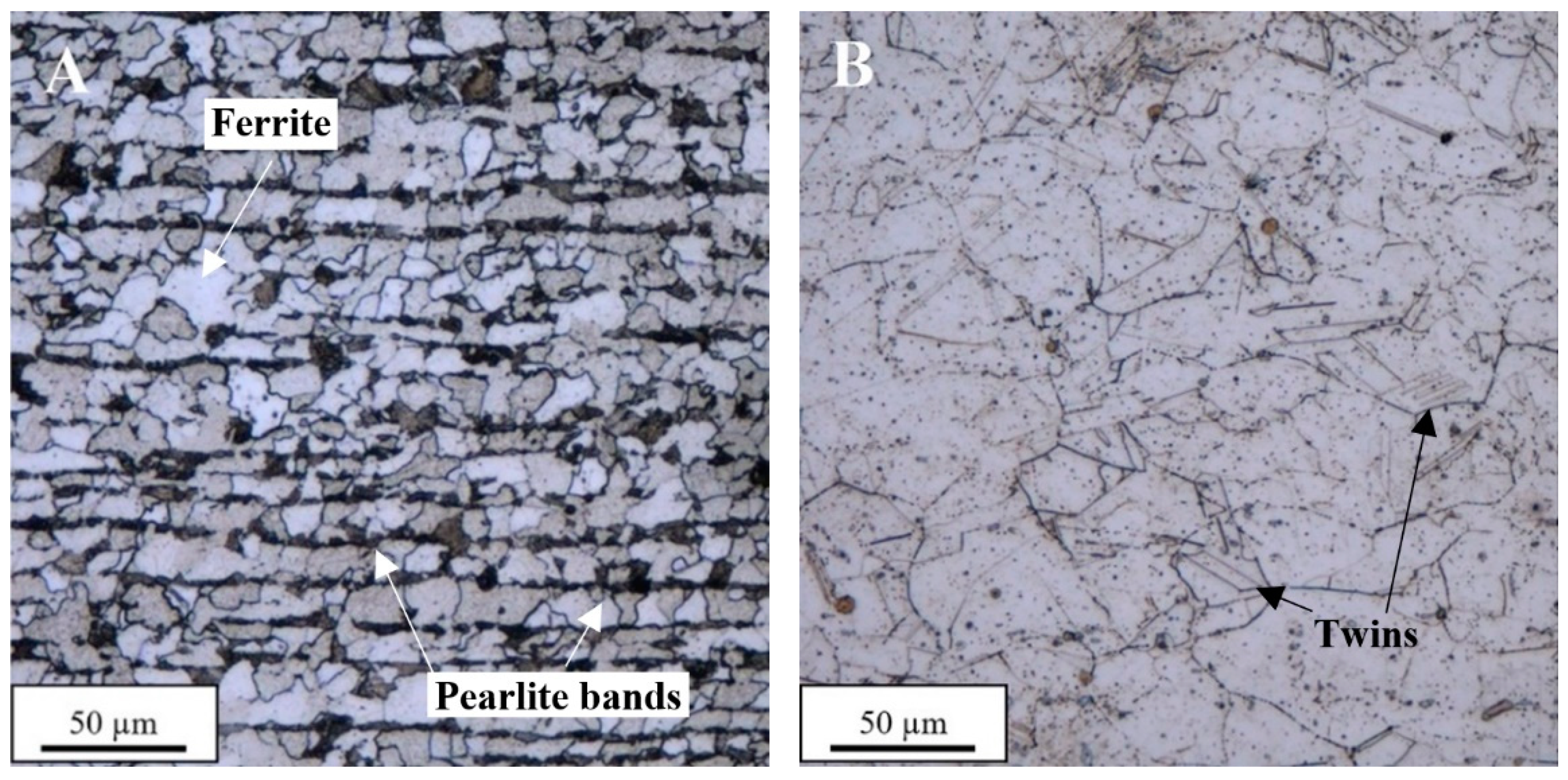
3.1. Microstructure of the Raw Materials

In the first part of the investigation the light microscopy observations of the base materials after etching have been performed. The microstructures of steel P355NH (Figure 3A) and Inconel 625 alloy (Figure 3B) in the as-received state are presented in Figure 3. As it can be observed, the steel P355NH has a ferrite-pearlite microstructure with noticeable pearlite bands, characteristic for the plates after rolling process. The microstructure of steel has fine equiaxial grains with their measured size equal to 15.5 ± 4.1 µm. At the same time, Inconel 625 alloy has far more heterogenous microstructure characterized by presence of twins and measured grain size of 49.4 ± 15.6 µm. Additionally, the microhardness of base materials has been measured with registered values of 150.6 ± 4.9 HV0.1 for steel P355NH and 249.6 ± 16.3 HV0.1 for Inconel 625 alloy, respectively.

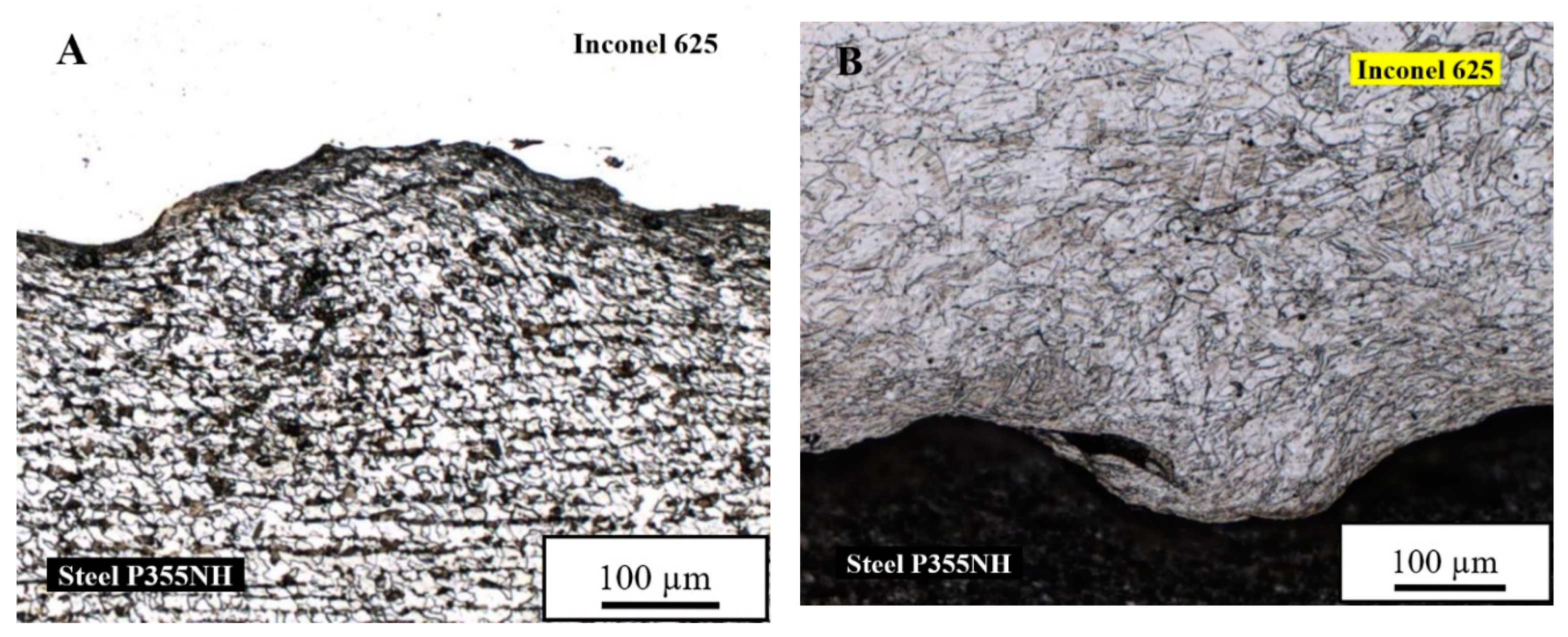
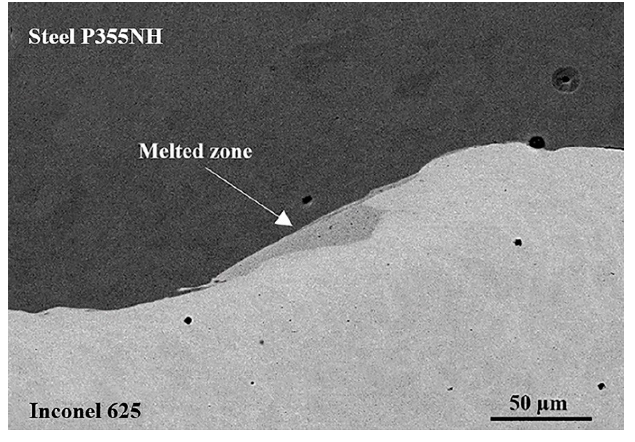
3.2. Microstructure of a Sample After Explosive Welding (InSt EXW) Joint

The obtained joint has a wavy structure, typical for explosively welded bond. The grains of both materials in the joint zone are deformed due to severe plastic deformation during collision, as it can be observed after etching of steel P355NH (Figure 4A) and Inconel 625 alloy (Figure 4B).
The observations using scanning electron microscope (BSE) show the occurrence of melted zones in the joint, where the two welded materials have been stirred together (Figure 5A). In the melted zones, the investigation revealed the presence of joint imperfections in the form of both cracks and fragments of steel P355NH surface layer, which underwent partial fragmentation during explosive welding process, as evidenced by linear analysis of the chemical composition (Figure 5B). The results of the chemical composition analysis indicate on the highest participation of Inconel 625 alloying elements in this area with small fluctuations near to the steel P355NH fragment.

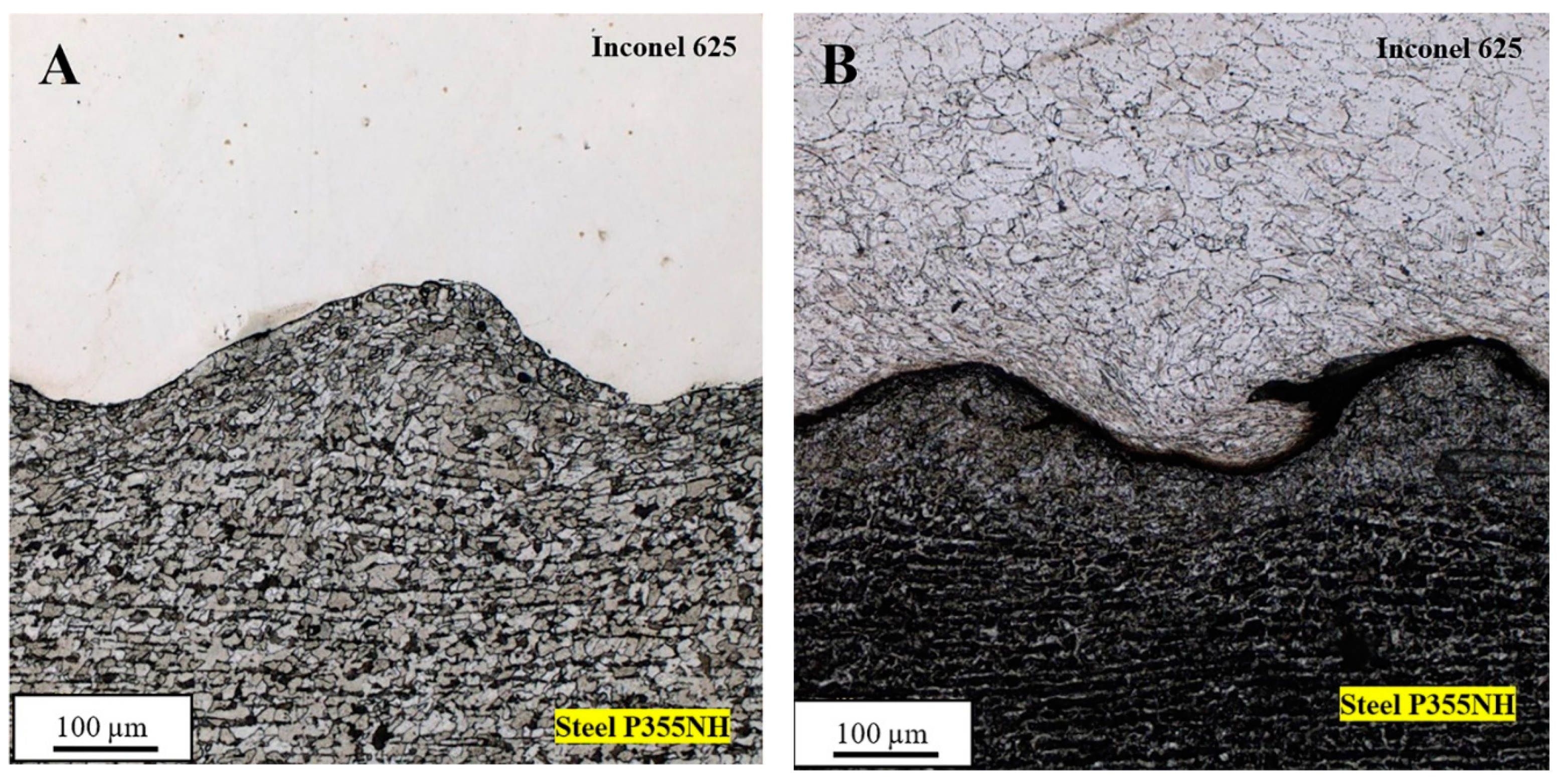
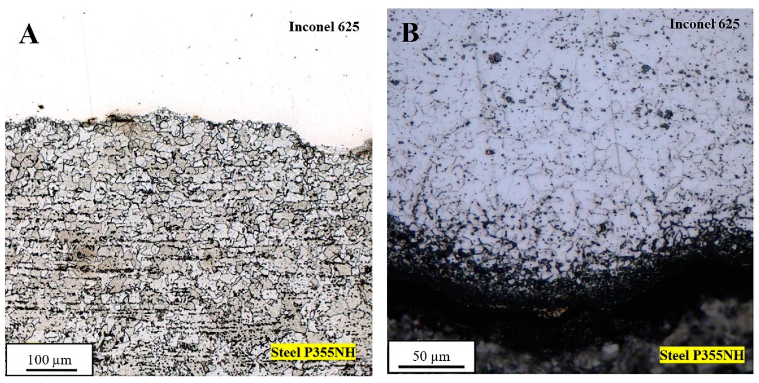
3.3. Microstructure of Sample After Post-Weld Stress Relief Annealing (InSt HTR) Joint

Post-weld stress relief annealing of Inconel 625/steel P355NH bimetallic clad-plate, performed at 620 °C for 90 min slightly influences the microstructure of the joint zone. The partial recrystallization of steel P355NH microstructure has been reported in the area of 20–30 μm from the joint line (Figure 6A). New, equiaxial grains formed on the joint line do not have deformation texture of previous compressed, elongated grains. The microstructure of steel P355NH farther from the joint line (about 30 μm) maintains the deformation texture and no recrystallized grains have been observed. On the other hand, the microstructure of Inconel 625 alloy did not reveal any visible changes in the grain morphology after stress relief annealing compared with its microstructure in the as-welded state (Figure 6B).
The scanning electron microscope observations did not show any visible changes in the concentration of the chemical elements in the joint zone (Figure 7). Both the bound between joined materials and melted zone are not affected by stress relief annealing in terms of chemical composition. The small imperfections in form of voids are possible to observe in melted zone, which is localized on one side of the intersurface wave (Figure 7).

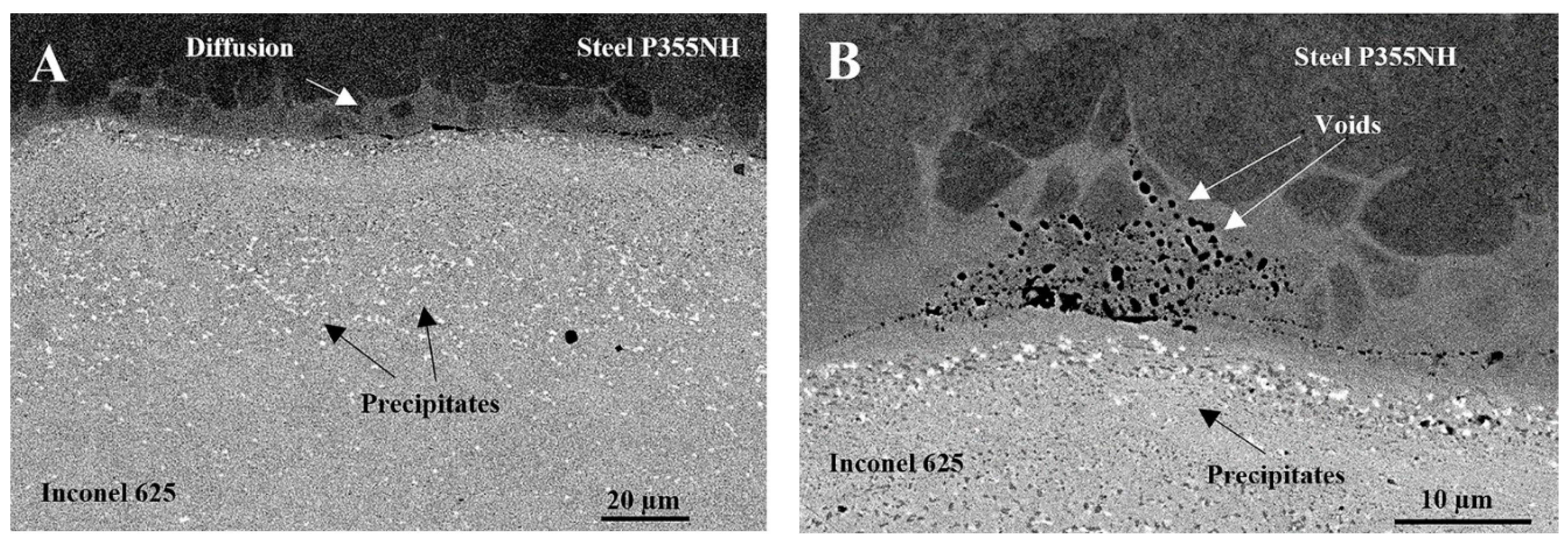
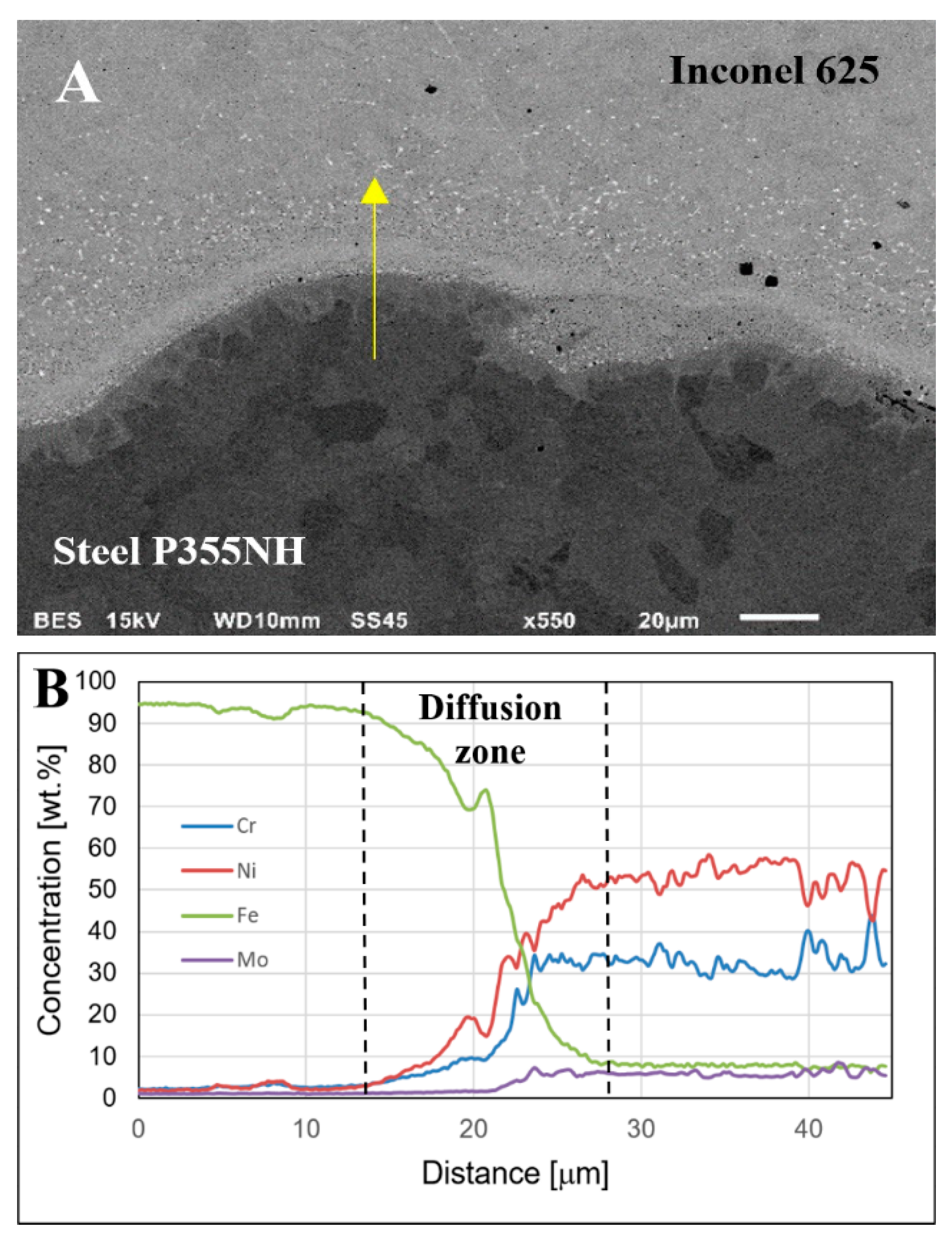
3.4. Microstructure of InSt HTN Joint

The microstructure of the joint subjected to normalizing at 910 °C for 30 min changed significantly. It has been reported that due to this post-weld heat treatment the complete recrystallization of microstructure of both joined materials—steel P355NH (Figure 8A) and Inconel 625 (Figure 8B) occurs. The welded materials have microstructures consisting of fine, equiaxial grains and no deformation texture is noticeable. The size of steel grains is about 20 μm, which is a typical value for this material after normalizing. Additionally, it has been observed the presence of ultrafine grains with size about 5 µm of steel P355NH on the joint line (Figure 8A). In case of Inconel 625 grains have size also about 20 µm with low participation of twins and significant amount of precipitates localized on grain boundaries.
The observations using scanning electron microscope show significant changes in the concentration of alloying elements in the joint area. It has been stated that alloying elements of Inconel 625 were found to diffuse into steel P355NH along grain boundaries (Figure 9A). Additionally, diffusion zone contains voids, which are localized mainly on grain boundaries and the joint line at the side of steel P355NH (Figure 9B). Another noticeable change compared with the joint in the as-welded state is formation of precipitates in the joint zone, which are localized in Inconel 625 alloy (Figure 9A,B).
Scanning electron microscope observations revealed the presence of two types of precipitates in Inconel 625 alloy—light precipitates (suggesting a high concentration of alloying elements heavier than nickel) and dark precipitates (high concentration of alloying elements lighter than nickel). The size of precipitates is about 0.5–1 µm (Figure 10A). In order to establish a chemical composition of precipitates EDX area analysis has been performed. Dark precipitates are characterized by high concentration of chromium and increased participation of molybdenum (Figure 10B). At the same time, it has been found that chemical composition of light precipitates has high molybdenum and niobium content (Figure 10C). Additionally, the presence of carbon in both types of precipitates has been reported.
The width of the diffusion zone in InSt HTN sample (Figure 11A) has been estimated using linear analysis of chemical composition (Figure 11B). The diffusion zone has about 15 μm width and can be divided into two sections: iron-rich and chromium and nickel-rich. (Figure 11B).

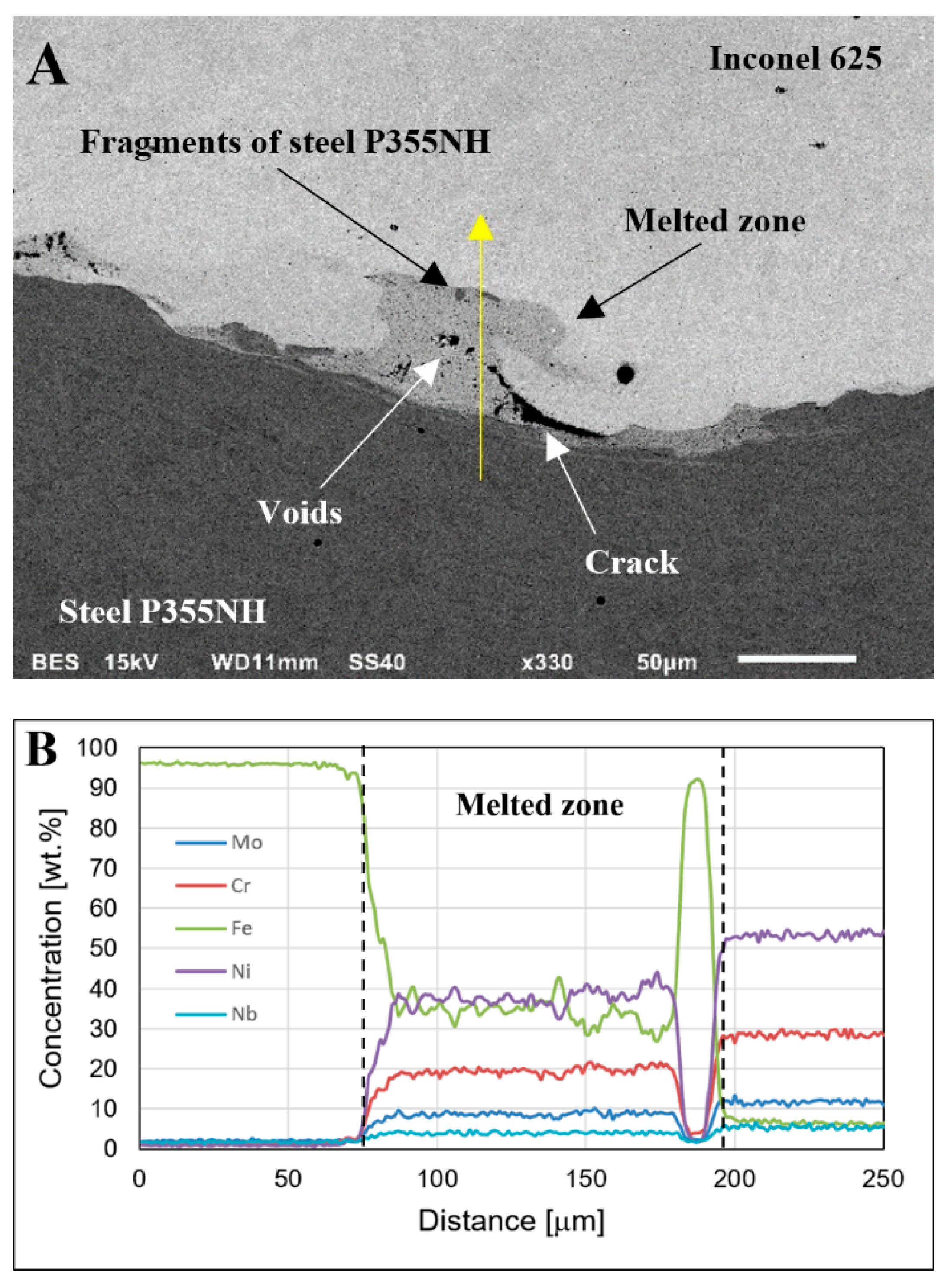
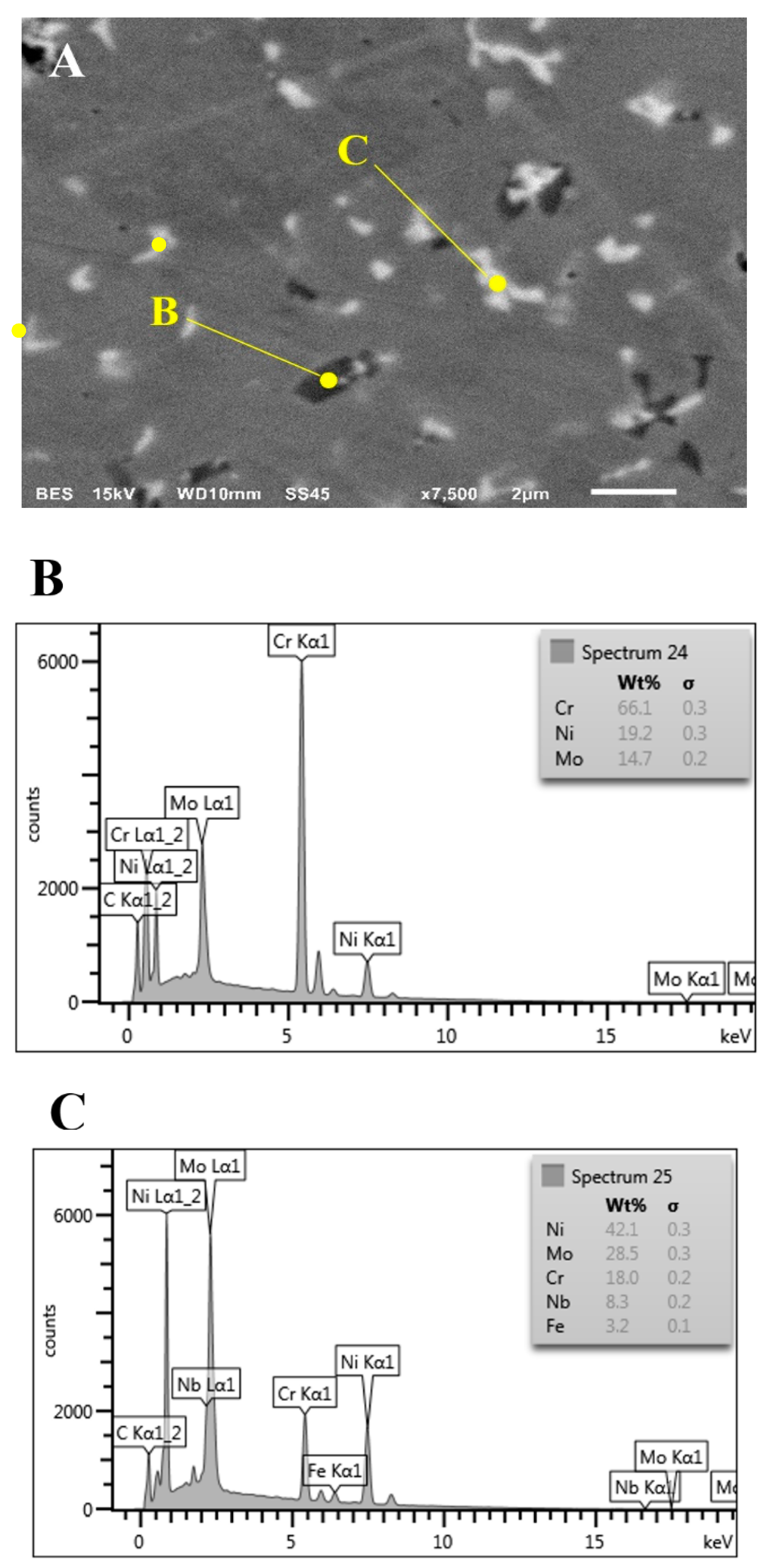
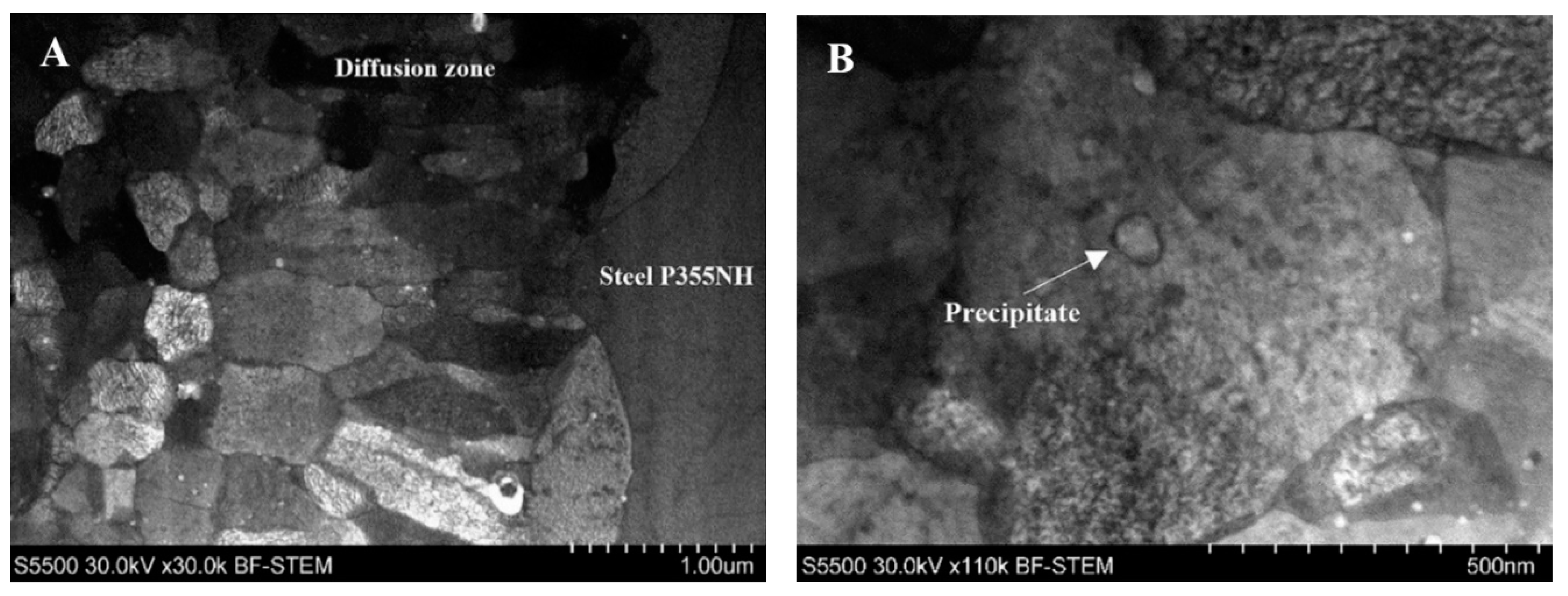
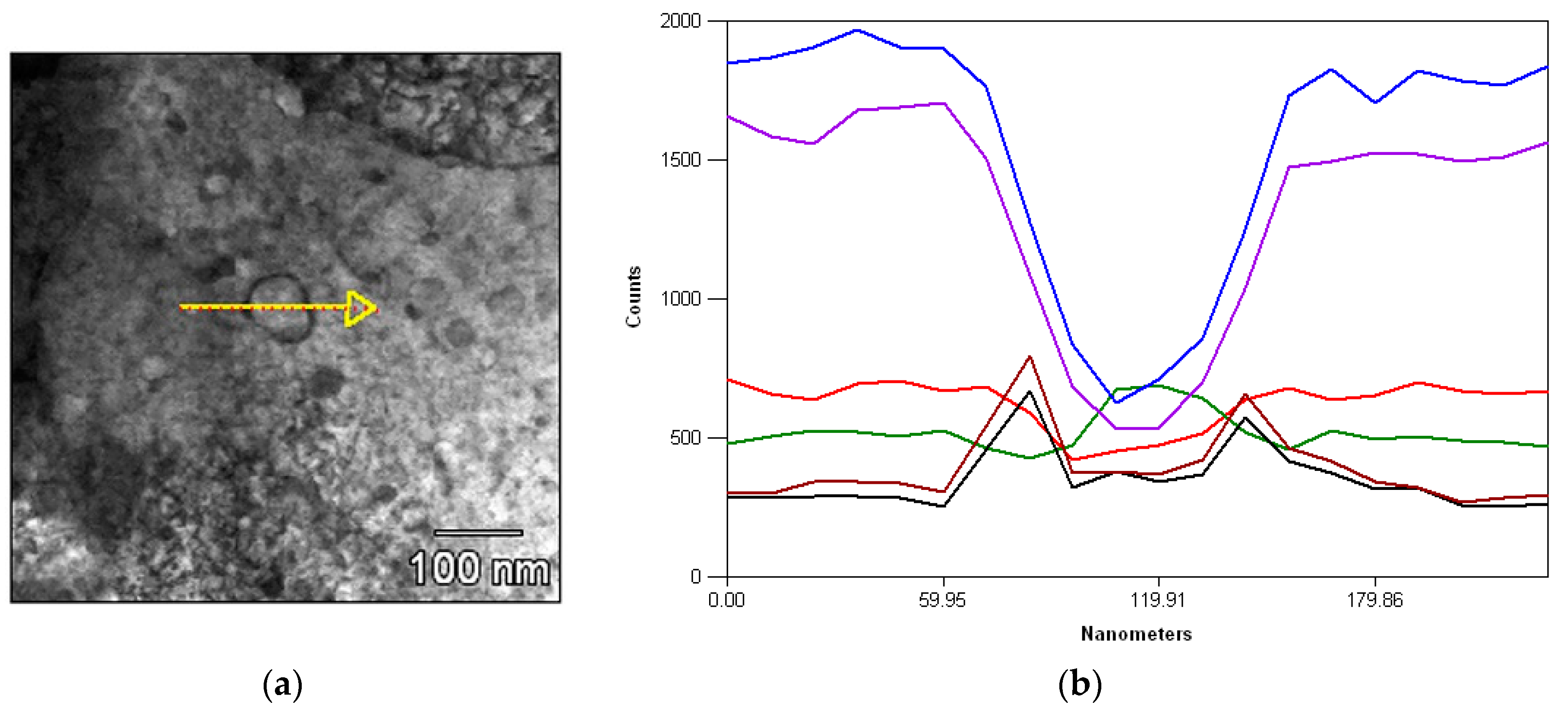
3.5. Scanning Transmission Electron Microscope Observations of the Diffusion Zone

Observations of the diffusion zone performed on scanning transmission electron microscope allow to investigate the grainy microstructure of this area. It has been stated that in terms of grain structure the diffusion zone consists of two subzones: area of equiaxed grains (at side of Inconel 625 alloy) and area of columnar grains (at side of steel P355NH) (Figure 12A). In both cases, the microstructure consists of ultrafine grains with their size within the range of 400 nm–1 μm. Predominantly, the finer grains close to Inconel 625 are equiaxed and columnar grains close to P355NH have slightly larger size. Additionally, it has been reported the occurrence of precipitates with their width about 50 nm in the diffusion zone (Figure 12B).
The linear analysis of chemical composition has been performed in order to investigate subzone of columnar grains (Figure 13). Results indicate on similar concentration of chromium and niobium in the analyzed area. On the other hand, the elements such as iron and nickel, which are main components of the diffusion zone, show significant fluctuations in their concentration in this zone. It has been reported that concentration of nickel decreases drastically on the border between columnar grains area of the diffusion zone and steel P355NH. At the same time the concentration of iron increases, also rapidly. The results of linear analysis together with scanning transmission electron microscopy observations of this area suggest the predominate role of nickel and iron concentration ratio in the forming of diffusion zone. The precipitates founded in this area were a subject of further investigation and observations performed on scanning transmission electron microscope reveal their specific structure consisted of core and shell (Figure 12B). In order to examine chemical composition of precipitate in the diffusion zone the linear analysis was performed (Figure 14). The shell-core structure has been confirmed in terms of chemical composition, since it has been reported that in the precipitate area there are significant differences in distribution of alloying elements. The shell has high concentration of niobium and molybdenum, while core consists of chromium and also of niobium and molybdenum (compared to the average value of concentration of these elements in the diffusion zone).

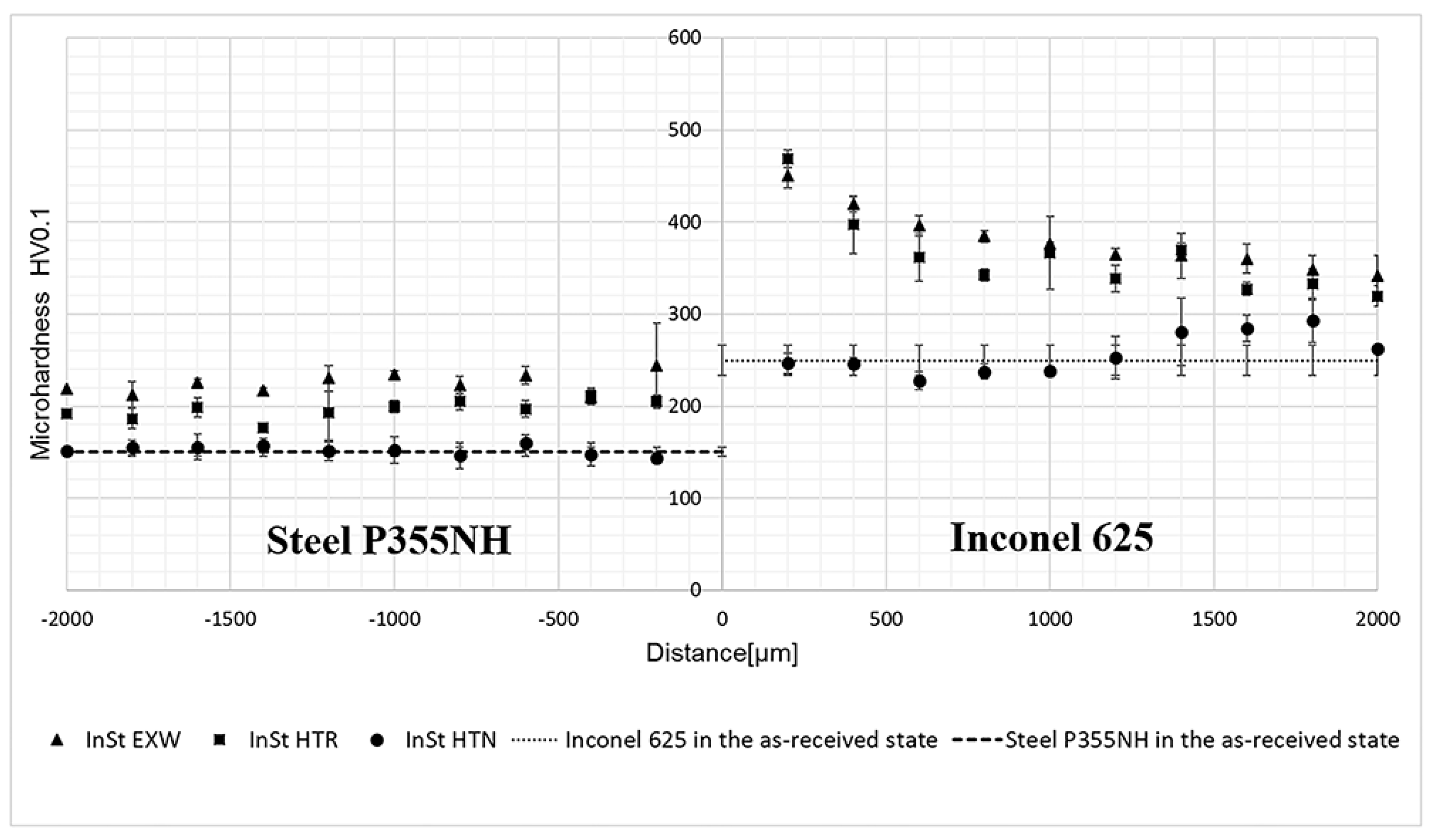
3.6. Microhardness Analysis

The influence of the explosive welding process on the joined materials in terms of strain hardening was established by microhardness analysis (Figure 15). The highest degree of strain hardening has been revealed close to the joint line, where welded materials were subjected to the severest plastic deformation due to high velocity collision during explosive welding process. In this area, the microhardness of Inconel 625 alloy increased by about 200 HV0.1 and in case of steel P355NH by about 100 HV0.1. Stress relief annealing reduced the microhardness of steel P355NH by about 40 HV0.1. It is mostly related to recrystallization of steel P355NH grains and presumably the decreasing of the residual stress of the welded materials in the joint zone. The post-weld heat treatment in the form of normalizing reduced the microhardness of steel P355NH and Inconel 625 to their baseline value, measured in the as-received state.

4. Discussion

Both heat treatments cause changes in the microstructure of investigated joint. Stress relief annealing has a lowest impact on grainy microstructure and leads only to partial recrystallization of steel P355NH grains in the joint zone. On the other hand normalizing the complete restructure of steel grainy microstructure has been noticed. It is a well-known fact that the higher degree of plastic deformation, the lower energy is necessary to initiate and complete heat-activated phenomena and therefore the recrystallization temperature is lower, which explains the incomplete restructure of the deformed steel structure after stress relief annealing. Additionally, it can be observed a disappear of pearlite bands close to the joint line, what can suggest the diffusion process of carbon into Inconel 625 alloy. Inconel contains chemical elements having a high affinity for carbon, such as chromium, molybdenum and niobium and for this reason carbon diffusion can result in formation of brittle carbides in the joint zone [15,41,42,43]. Inconel 625 isothermal transformation diagram shows that the parameters of the normalizing are close to the area of carbides formation, especially MC and M6C types (Figure 16).
As it was mentioned in the introduction part, the plastic deformation of Inconel 625 alloy, which took place in the joint results in reducing of the energy of heat-activated processes, including precipitate processes. The diffusion of carbon from steel P355NH into Inconel 625 alloy is an additional factor, which has a significant impact on the carbides precipitation processes in the layer of Inconel 625 near to the joint line. Scanning electron microscopy observations of sample subjected to the normalizing revealed presence of precipitates in Inconel 625 close to the joint line. The results of chemical composition analysis of precipitates indicate to two types of compounds: light, molybdenum-rich and dark, chromium-rich. The presence of carbon in both precipitates has been reported. The literature on the diffusion bonding of Inconel 625 and low-alloy steel describes both morphology and chemical composition of carbides formed in that bimetallic system, identifying the precipitates as carbides of M6C type in the case of high molybdenum concentration and of M23C6 type in the case of high chromium concentration [41,43]. Additionally, M6C carbides have been characterized by increased concentration of niobium and iron what has been confirmed in this investigation [41]. Scanning electron microscopy observation of the diffusion zone formed due to normalizing, allow one to draw a conclusion that chemical elements of Inconel 625 alloy diffuse into steel P355NH along grain boundaries. Diffusion zone has about 15 μm width and can be divided into two sections in terms of iron, nickel and chromium concentrations. The first, iron-rich section consists of about 90% of iron and below 10% of nickel and chromium. An analysis of the Fe-Ni-Cr phase equilibrium diagram suggests that this section is composed predominantly of γ phase and very small amount of α phase (Figure 17). At the same time, the second section is characterized by high concentration of nickel (ca. 45%) and chromium (ca. 30%). Phase diagram analysis also indicates on γ phase, as the main component of the section with the small addition of α’ phase (Figure 17).
Scanning transmission electron microscopy observations, allowed to investigate the diffusion zone microstructure, which consists of equiaxed, columnar grains with presence of 50 nm chromium-rich precipitates having core-shell structure. It can be stated that both observed diffusion-based phenomena in sample after normalizing, including diffusion zone with presence of voids and carbides in Inconel 625 alloy have their detrimental effect on the joint strength. The carbides localized in Inconel 625 alloy layer, also result in decreasing of material coherence at the most crucial region—the joint. These factors might cause the deterioration of the joint quality established by the shear test in the previous investigation performed by the authors of this paper [22].

5. Conclusions

Analysis of Inconel 625/steel P355NH joint microstructure in the as-welded state and after two different, separated types of heat treatment (stress relief annealing and normalizing) allowed the following conclusions to be drawn.
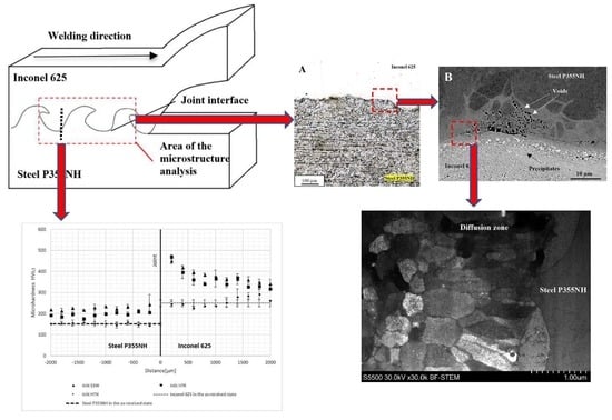
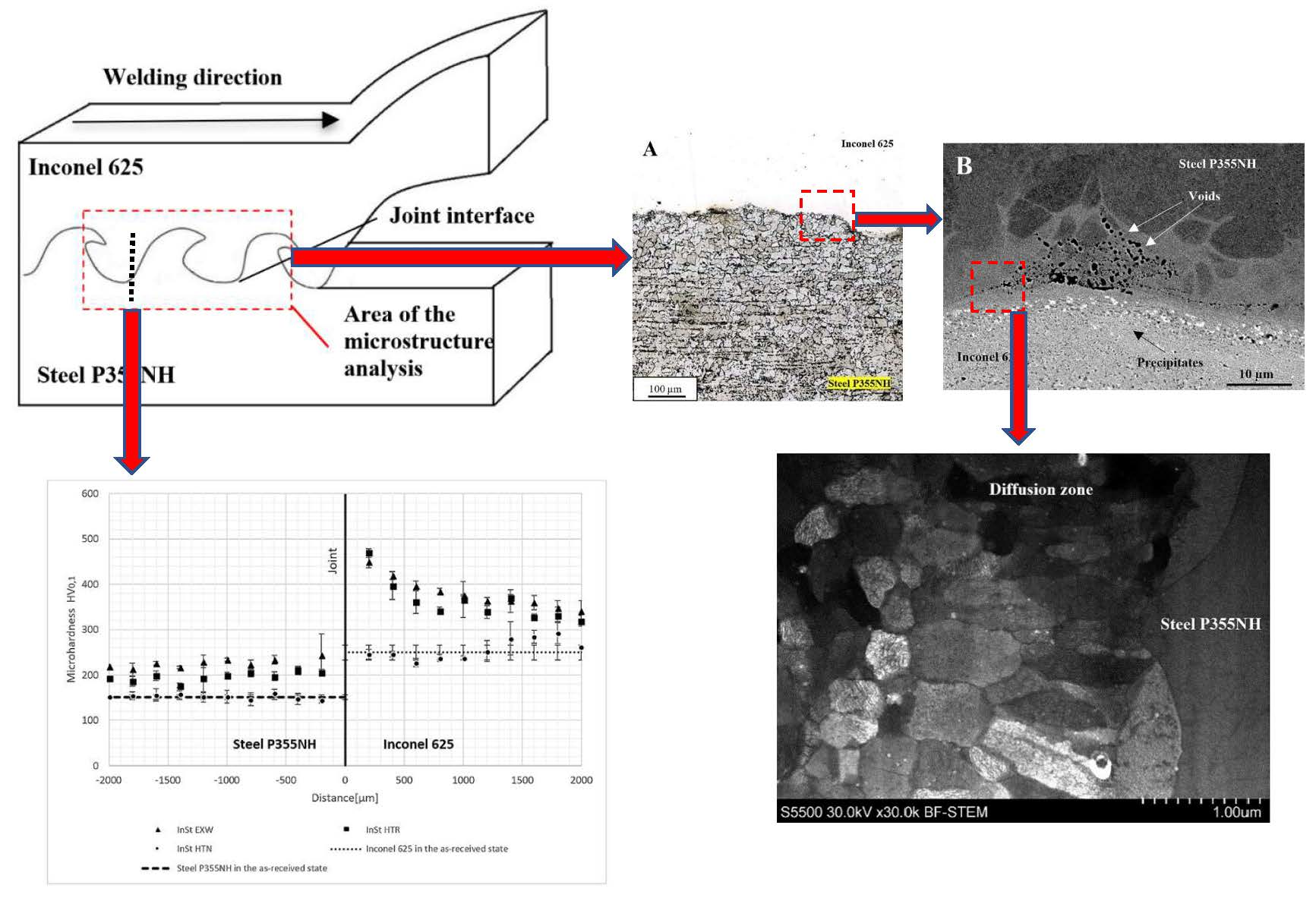
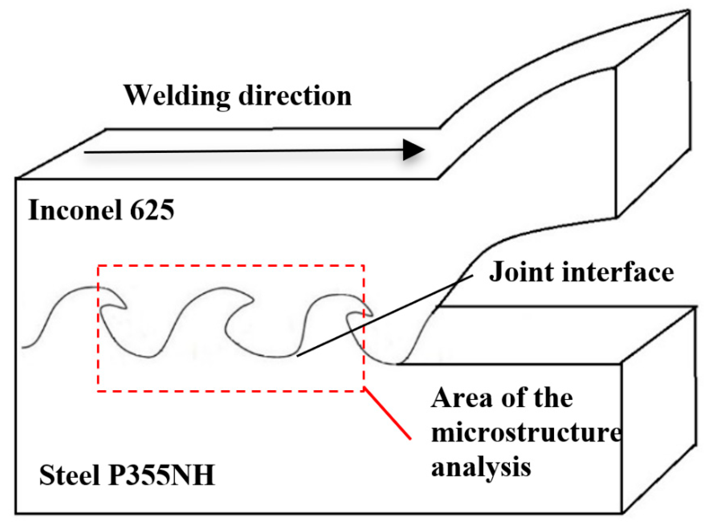
  • The explosive welding process allowed to obtain joint between steel P355NH and Inconel 625 alloy. The wavy-shape joint was found to include melted zones having high concentration of imperfections such as cracks, voids and fragments of steel P355NH surface layer.
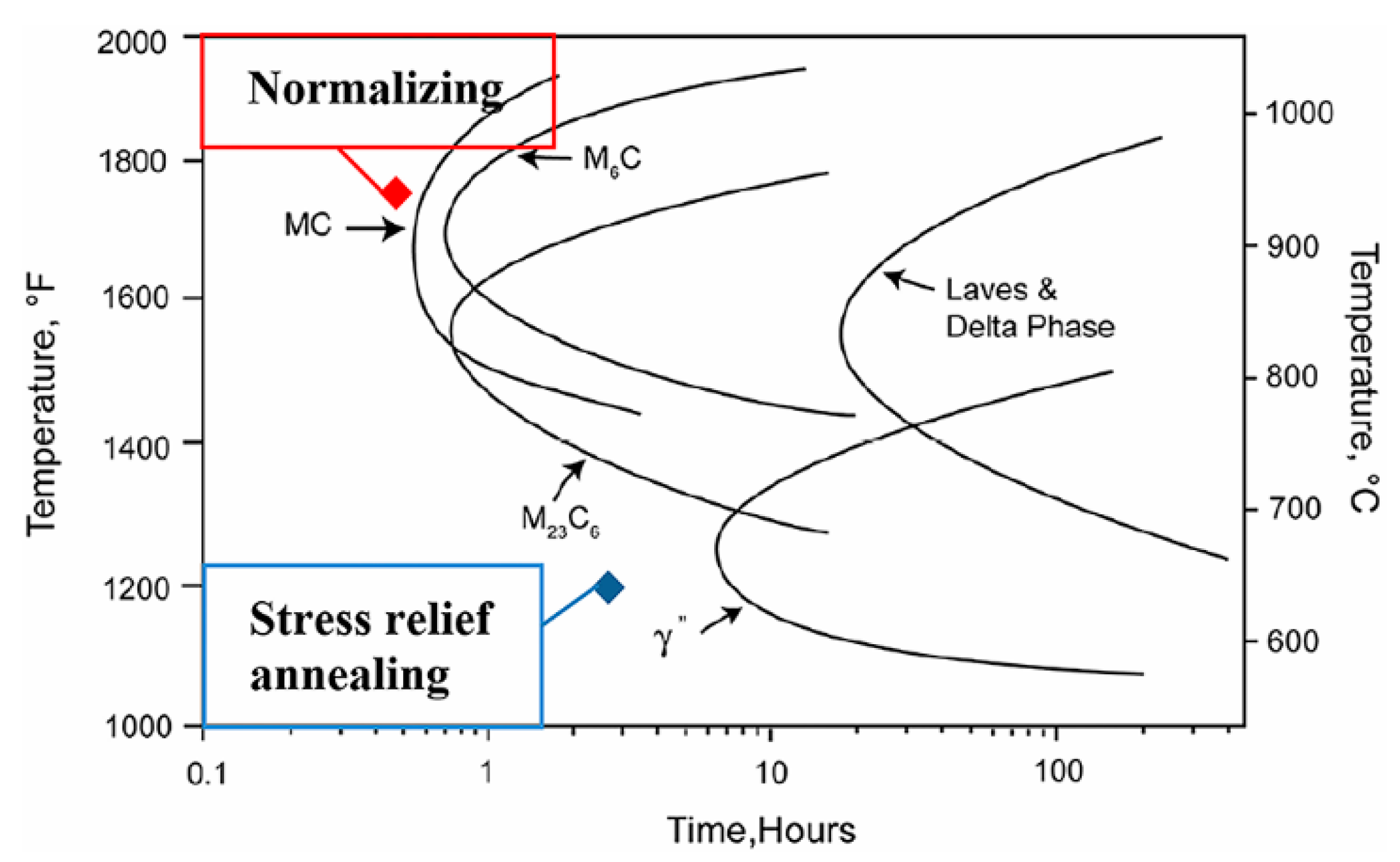
  • Stress relief annealing (620 °C/90 min) led to partial recrystallization of steel P355NH in the joint area. At the same time no changes in the grainy microstructure of Inconel 625 and chemical composition of the joint have been noticed.
  • Heat treatment in the form of normalizing (910 °C/30 min) resulted in complete recrystallization of grainy microstructure of both bonded materials.
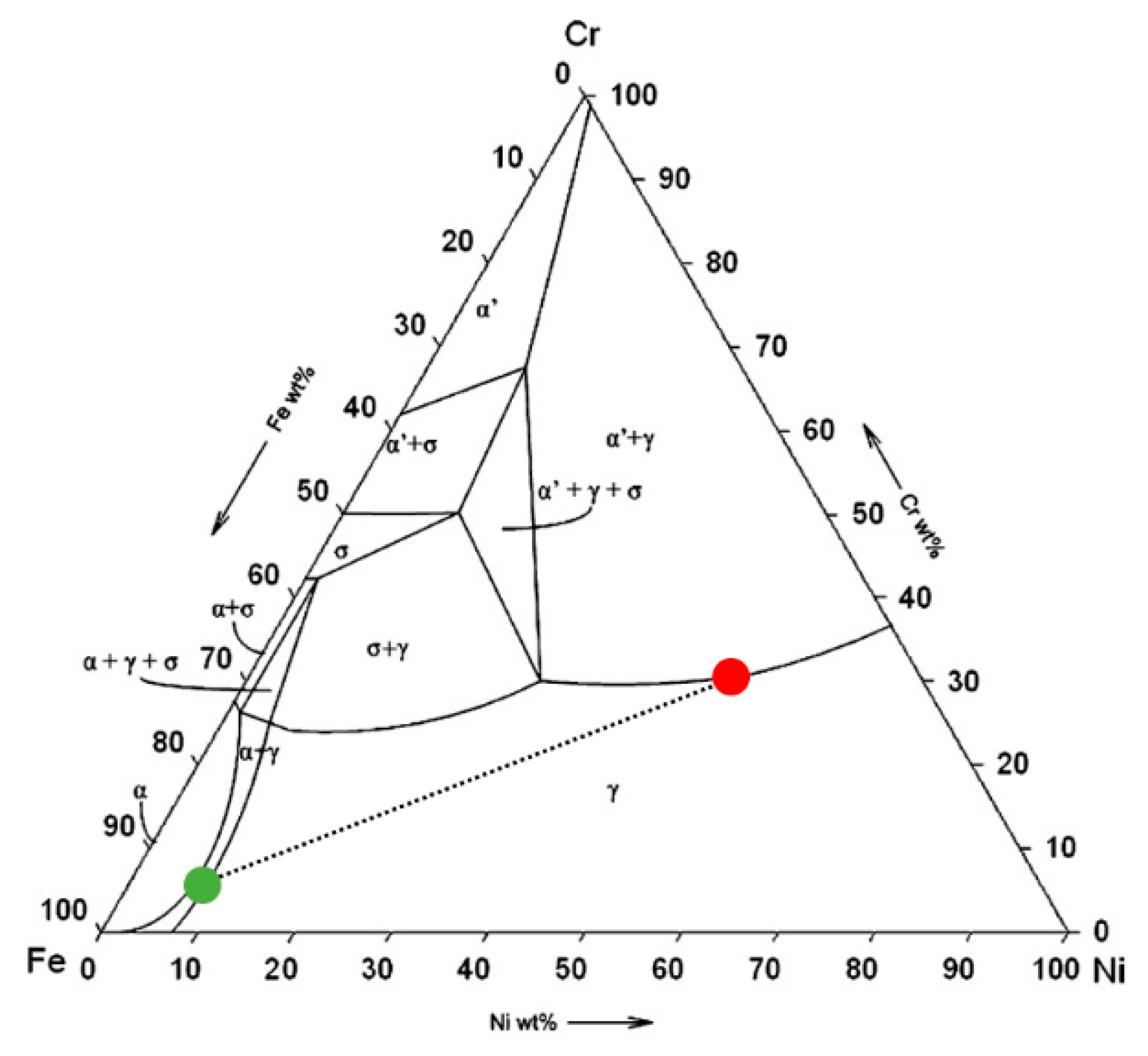
  • As the result of normalizing the diffusion of Inconel 625 alloying elements into steel P355NH took place along the grain boundaries with tendency to formation of voids.
  • Additionally, another effect of post-weld normalizing is the formation of M6C and M23C6 carbides in Inconel 625 alloy in the joint zone.

Author Contributions

For research articles with several authors, a short paragraph specifying their individual contributions must be provided. The following statements should be used “conceptualization, R.K.; methodology, M.W. and M.G.; formal analysis, R.K.; investigation, R.K., M.W. and M.G.; writing—original draft preparation, R.K. and M.W.; writing—review and editing, M.W. and L.Ś.; supervision, L.Ś.”, please turn to the CRediT taxonomy for the term explanation. Authorship must be limited to those who have contributed substantially to the work reported.

Funding

This research was funded by The National Centre for Research and Development of Poland, grant number: DZP/M-ERA.NET-2013/2309/2014.

Conflicts of Interest

The authors declare no conflict of interest.

References

  1. Karlsdóttir, S.N.; Hjaltason, S.M.; Ragnarsdóttir, K.R. Corrosion behavior of materials in hydrogen sulfide abatement system at Hellisheiði geothermal power plant. Geothermics 2017, 70, 222–229. [Google Scholar] [CrossRef]
  2. Tomarov, G.V.; Shipkov, A.A. Erosion–Corrosion of Metals in Multicomponent Geothermal Flows. Therm. Eng. 2006, 53, 188–194. [Google Scholar] [CrossRef]
  3. Durejko, T.; Ziętala, M.; Polkowski, W.; Czujko, T. Thin wall tubes with Fe3Al/SS316L graded structure obtained by using laser engineered net shaping technology. Mater. Des. 2014, 63, 766–774. [Google Scholar] [CrossRef]
  4. Strasser, A.; Santucci, J.; Lindquist, K.; Yario, W.; Stern, G.; Goldstein, L.; Joseph, L. Evaluation of Stainless Steel Cladding for Use in Current Design LWRs; Electric Power Research Institute: Palo Alto, CA, USA, 1982. [Google Scholar]
  5. Kosturek, R.; Wachowski, M.; Sniezek, L.; Gloc, M.; Sobczak, U. The effects of the heat treatment on the microstructure of Inconel 625/steel bimetal joint obtained by explosive welding. In Proceedings of the International Conference on Advanced Functional Materials and Composites (ICAFMC2018), MATEC Web of Conferences 242, Barcelona, Spain, 5–6 September 2018. [Google Scholar] [CrossRef]
  6. British Standard. Seamless Steel Tubes for Pressure Purposes. Technical Delivery Conditions; Alloy fine grain steel tubes; EN 10216-3:2002; British Standard: London, UK, 2002. [Google Scholar]
  7. Farrer, J.C.M. The Alloy Tree: A Guide to Low-Alloy Steels, Stainless Steels, and Nickel-Base Alloys; Woodhead Publishing: Oxford, UK, 2004; ISBN 1-85573-766-3. [Google Scholar]
  8. Pokorny, Z.; Barborak, O.; Hruby, V. Characteristics of plasma nitrided layers in deep holes. Kovove Mater. 2012, 50, 209–212. [Google Scholar] [CrossRef] [Green Version]
  9. Pokorny, Z.; Kadlec, J.; Hruby, V. Hardness of plasma nitrided layers created at different conditions. Chem. Listy 2011, 105, 717–720. [Google Scholar]
  10. Pokorny, Z.; Dobrocky, D.; Kadlec, J. Influence of alloying elements on gas nitriding process of high-stressed machine parts of weapons. Kovove Mater. 2018, 56, 97–103. [Google Scholar] [CrossRef]
  11. Rajani, H.R.Z.; Mousavi, S.A.A.A. On Critical Criteria for Shifting Towards Plastic Strain Localization during Explosive Cladding of Inconel 625 on Low-Carbon Steel. Combust. Explos. Shock Waves 2013, 49, 2. [Google Scholar] [CrossRef]
  12. Rajani, H.R.Z.; Mousavi, S.A.A.A. The Role of Impact Energy in Failure of Explosive Cladding of Inconel 625 and Steel. J. Fail. Anal. Prev. 2012, 12, 6. [Google Scholar] [CrossRef]
  13. Rajani, H.R.Z.; Mousavi, S.A.A.A. The effect of explosive welding parameters on metallurgical and mechanical interfacial features of Inconel 625/plain carbon steel bimetal plate. Mater. Sci. Eng. A 2012, 556, 454–464. [Google Scholar] [CrossRef]
  14. Rajani, H.R.Z.; Mousavi, S.A.A.A.; Madani, S.F. Comparison of corrosion behavior between fusion cladded and explosive cladded Inconel 625/plain carbon steel bimetal plates. Mater. Des. 2013, 43, 467–474. [Google Scholar] [CrossRef]
  15. Wachowski, M.; Gloc, M.; Ślęzak, T.; Płociński, T.; Kurzydłowski, K.J. The Effect of Heat Treatment on the Microstructure and Properties of Explosively Welded Titanium-Steel Plates. J. Mater. Eng. Perform. 2017, 26, 945–954. [Google Scholar] [CrossRef] [Green Version]
  16. Bristowe, W.; Pearson, M.; Stunguris, C.; Gothard, S.A. Comparison of Refractory Lined Carbon Steel and Titanium EXW Clad Pressure Vessels for Specific Operating Conditions. In Proceedings of the 26th Annual Conference of the International Titanium Association, Orlando, FL, USA, 3–6 October 2010. [Google Scholar]
  17. Prażmowski, M.; Rozumek, D.; Paul, H. Static and fatigue tests of bimetal Zr-steel made by explosive welding. Eng. Fail. Anal. 2017, 75, 71–81. [Google Scholar] [CrossRef]
  18. Findik, F. Recent developments in explosive welding. Mater. Des. 2011, 32, 1081–1093. [Google Scholar] [CrossRef]
  19. Rozumek, D.; Marciniak, Z. Fatigue tests of bimetal zirconium-steel made by explosive welding. Procedia Eng. 2016, 160, 137–142. [Google Scholar] [CrossRef]
  20. Rozumek, D.; Marciniak, Z. Crack growth of explosive welding zirconium-steel bimetal subjected to cyclic bending. Frattura ed Integrità Strutturale 2017, 42, 40–45. [Google Scholar] [CrossRef]
  21. Prasanthi, T.N.; C Sudha, R.; Saroja, S. Explosive cladding and post-weld heat treatment of mild steel and titanium. Mater. Des. 2016, 93, 180–193. [Google Scholar] [CrossRef]
  22. Kosturek, R.; Najwer, M.; Nieslony, P.; Wachowski, M. Effect of Heat Treatment on Mechanical Properties of Inconel 625/Steel P355NH Bimetal Clad Plate Manufactured by Explosive Welding, Advances in Manufacturing. Lect. Notes Mech. Eng. 2018, 681–686. [Google Scholar] [CrossRef]
  23. Pocica, A.; Bański, R.; Waindok, P.; Szulc, Z.; Gałka, A. Wpływ czasu obróbki cieplnej na własności bimetalu tytan-stal. In Proceedings of the XVI Międzynarodowa Konferencja, Spawanie w Energetyce, Opole-Jarnołtówek, Poland, 23–25 September 2008. [Google Scholar]
  24. Jiang, H.T.; Yan, X.G.; Liu, J.X.; Duan, X.G. Effect of heat treatment on microstructure and mechanical property of Ti–steel explosive-rolling clad plate. Trans. Nonferrous Metals Soc. China 2014, 24, 697–704. [Google Scholar] [CrossRef]
  25. Mousavi, S.A.A.A.; Sartangi, P.F. Effect of post-weld heat treatment on the interface microstructure of explosively welded titanium–stainless steel composite. Mater. Sci. Eng. A 2008, 494, 329–336. [Google Scholar] [CrossRef]
  26. Trueb, L.F. Microstructural effects of heat treatment on the bond interface of explosively welded metals. Metall. Trans. A 1971, 2, 145–153. [Google Scholar] [CrossRef]
  27. Maliutina, I.; Mali, V.; Skorokhod, K.A.; Bataev, A. Effect of Heat-Treatment on the Interface Microstructure of Explosively Welded Stainless Steel—Bronze Composite. Appl. Mech. Mater. 2015, 698, 495–500. [Google Scholar] [CrossRef]
  28. Findik, F.; Yilmaz, R.; Somyurek, T. The effects of heat treatment on the microstructure and microhardness of explosive welding. Sci. Res. Essays 2011, 6, 4141–4151. [Google Scholar] [CrossRef]
  29. Fronczek, D.M.; Chulist, R.; Litynska-Dobrzynska, L.; Kac, S.; Schell, N.; Kania, Z.; Szulc, Z.; Wojewoda-Budka, J. Microstructure and kinetics of intermetallic phase growth of three-layered A1050/AZ31/A1050 clads prepared by explosive welding combined with subsequent annealing. Mater. Des. 2017, 130, 120–130. [Google Scholar] [CrossRef]
  30. Fronczek, D.M.; Chulist, R.; Szulc, Z.; Wojewoda-Budka, J. Growth kinetics of TiAl3 phase in annealed Al/Ti/Al explosively welded clads. Mater. Lett. 2017, 198, 160–163. [Google Scholar] [CrossRef]
  31. Wang, X.G.; Li, X.G.; Yan, F.J.; Wang, C.G. Effect of heat treatment on the interfacial microstructure and properties of Cu-Al joints. Weld. World 2017, 61, 187–196. [Google Scholar] [CrossRef]
  32. Chen, C.Y.; Chen, H.L.; Hwang, W.S. Influence of Interfacial Structure Development on the Fracture Mechanism and Bond Strength of Aluminum/Copper Bimetal Plate. Metall. Trans. A 2006, 47, 1232–1239. [Google Scholar] [CrossRef] [Green Version]
  33. Atabaki, M.M.; Nikodinovski, M.; Chenier, P.; Ma, J.; Harooni, M.; Kovacevic, R. Welding of Aluminum Alloys to Steels: An Overview. J. Manuf. Sci. Prod. 2014, 14, 59–78. [Google Scholar] [CrossRef]
  34. Petrzak, P.; Kowalski, K.; Blicharski, M. Analysis of Phase Transformations in Inconel 625 Alloy during Annealing. Acta Phys. Pol. A 2016, 130, 4. [Google Scholar] [CrossRef]
  35. Shoemaker, L.E. Alloys 625 and 725: Trends in properties and applications. In Superalloys 718, 625, 706 and Derivatives; The Minerals, Metals & Materials Society: Pittsburgh, PA, USA, 2005; pp. 409–418. [Google Scholar]
  36. Sukumaran, A.; Gupta, R.K.; Kumar, V.A. Effect of Heat Treatment Parameters on the Microstructure and Properties of Inconel-625 Superalloy. J. Mater. Eng. Perform. 2017, 26, 3048–3057. [Google Scholar] [CrossRef]
  37. Maj, P.; Adamczyk-Cieslak, B.; Slesik, M.; Mizera, J.; Pieja, T.; Sieniawski, J.; Gancarczyk, T.; Dudek, S. The Precipitation Processes and Mechanical Properties of Aged Inconel 718 Alloy After Annealing. Arch. Metall. Mater. 2017, 62, 1695–1702. [Google Scholar] [CrossRef] [Green Version]
  38. Rongbin, L.; Mei, Y.; Wenchang, L.; Xianchang, H. Effects of Cold Rolling on Precipitates in Inconel 718 Alloy. J. Mater. Eng. Perform. 2002, 11, 504–508. [Google Scholar] [CrossRef]
  39. Liu, W.C.; Xiao, F.R.; Yao, M.; Yuan, H.; Chen, Z.L.; Jiang, Z.Q.; Wang, S.G.; Li, W.H. Influence of cold rolling on the precipitation kinetics of γ′′ and δ phases in Inconel 718 alloy. J. Mater. Sci. Lett. 1998, 17, 245–247. [Google Scholar] [CrossRef]
  40. Yunpeng, M.; Yongchang, L.; Chenxi, L.; Chong, L.; Liming, Y.; Qianying, G.; Huijun, L. Effects of cold rolling on the precipitation kinetics and the morphology evolution of intermediate phases in Inconel 718 alloy. J. Alloys Compd. 2015, 649, 949–960. [Google Scholar] [CrossRef]
  41. López, B.; Gutiérrez, I.; Urcola, J.J. Study of the Microstructure Obtained after Diffusion Bonding Inconel 625 to Low Alloy Steel by Hot Uniaxial Pressing or Hipping. Mater. Charact. 1992, 28, 49–59. [Google Scholar] [CrossRef]
  42. Chiba, A.; Nishida, M.; Morizono, Y.; Imamura, K. Bonding characteristics and diffusion barrier effect of the TiC phase formed at the bonding interface in an explosively welded titanium/high-carbon steel clad. J. Phase Equilib. 1995, 16, 411–415. [Google Scholar] [CrossRef]
  43. Gutierrez, I.; Urcola, J.J.; Bilbao, J.M.; Villar, L.M. Bonding by hot extrusion of Incoloy 825 and Duplex 2205 to low alloy steel. Mater. Sci. Technol. Ser. 1991, 7, 761–769. [Google Scholar] [CrossRef]
  44. Yen, Y.; Su, J.; Huang, D. Phase equilibria of the Fe–Cr–Ni ternary systems and interfacial reactions in Fe–Cr alloys with Ni substrate. J. Alloy Compd. 2008, 457, 270–278. [Google Scholar] [CrossRef]
Figure 1. Area from which samples of bimetallic-clad plates were collected for microstructure investigation.
Metals 09 00246 g001
Figure 2. The scheme of microhardness testing.
Metals 09 00246 g002
Figure 3. Microstructure of materials in the as-received state: (A) steel P355NH; (B) Inconel 625.
Metals 09 00246 g003
Figure 4. Microstructure of the joint in sample after explosive welding (InSt EXW): (A) after etching of steel P355NH; (B) after etching of Inconel 625 alloy.
Metals 09 00246 g004
Figure 5. Melted zone in InSt EXW sample: (A) microstructure of the melted zone; (B) with linear analysis of the chemical composition (yellow marker).
Metals 09 00246 g005
Figure 6. Microstructure of the joint in sample after post-weld stress relief annealing (InSt HTR) sample: (A) after etching of steel P355NH; (B) after etching of Inconel 625 alloy.
Metals 09 00246 g006
Figure 7. Image of the joint in InSt HTR sample from the scanning electron microscope.
Metals 09 00246 g007
Figure 8. Microstructure of the joint in post-weld normalizing (InSt HTN) sample: (A) after etching of steel P355NH; (B) after etching of Inconel 625 alloy.
Metals 09 00246 g008
Figure 9. Image of the joint in InSt HTN sample from the scanning electron microscope: (A) diffusion of alloying elements through the joint line and precipitates in Inconel 625 alloy; (B) diffusion zone with visible voids along the grain boundaries and the joint line.
Metals 09 00246 g009
Figure 10. Precipitates in Inconel 625 (A) together with the results of chemical composition analysis of dark precipitate (B) and light precipitate (C).
Metals 09 00246 g010
Figure 11. Image of the joint in InSt HTN sample: (A) microstructure of the joint; (B) linear analysis of the chemical composition (yellow marker).
Metals 09 00246 g011
Figure 12. Image of the diffusion zone grainy microstructure in InSt HTN sample (A); Image of the precipitate in the diffusion zone (B).
Metals 09 00246 g012
Figure 13. The results of linear analysis of the chemical composition of columnar grains in the diffusion zone. Lines designation: Fe (green), Ni (blue), Cr (red), Nb (purple).
Metals 09 00246 g013
Figure 14. The results of linear analysis of the precipitate in the diffusion zone. Lines designation: Fe (blue), Ni (purple), Cr (green), Nb (black), Mo (burgundy), C (red).
Metals 09 00246 g014
Figure 15. The results of microhardness analysis.
Metals 09 00246 g015
Figure 16. Inconel 625 isothermal transformation diagram [35]. Parameters of stress relief annealing and normalizing have been marked.
Metals 09 00246 g016
Figure 17. Fe–Ni–Cr phase diagram [44] together with marked compositions of: iron-rich section (green dot) and nickel-chromium-rich section (red dot).
Metals 09 00246 g017
Table 1. Chemical composition of the joined alloys [% mass].
Inconel 625AlCrFeMoNbTiNi
0.1621.54.68.73.320.18Base
St. P355NHCCrSiMnNiCuFe
0.180.020.351.190.220.2Base

