Article

The Influence of Heat Treatment Parameters on the Cracks Growth under Cyclic Bending in St-Ti Clad Obtained by Explosive Welding

by
Dariusz Rozumek
* and
Grzegorz Kwiatkowski
Department of Mechanics and Machine Design, Opole University of Technology, Mikolajczyka 5, 45-271 Opole, Poland
*
Author to whom correspondence should be addressed.
Metals 2019, 9(3), 338; https://doi.org/10.3390/met9030338
Submission received: 15 February 2019 / Revised: 12 March 2019 / Accepted: 14 March 2019 / Published: 17 March 2019
(This article belongs to the Special Issue Explosive Welding)

Abstract

:
The current work focuses on the effect of time and temperature of annealing on the change in the structure and cracks growth and fatigue life of the steel-titanium bimetal obtained by explosive welding. Cyclic bending tests were performed for different levels of annealing temperature on bimetal specimens of a rectangular cross-section. The fatigue crack growth was measured by microscopy. Structure changes of steel, titanium and bond area resulted in a different micro-hardness distribution. The relationship between the level of the annealing temperature, the propagation of fatigue cracks, structure changes and micro-hardness level is analyzed. The heat treatment of the bimetal at the temperature of 500 °C does not result in considerable changes in the structure of steel and titanium. The diffusion of carbon to titanium was observed. A higher annealing temperature results in a lower fatigue life. Also, for a given annealing temperature, a longer annealing time results in a higher fatigue life.

Graphical Abstract

1. Introduction

Although explosive welding has been used for many years, the mechanisms acting in the materials are not fully known [1,2]. The research centers involved in analyzing these mechanisms worldwide are: Clad Metal Products USA, the Russian Academy of Science, University in Zagreb Croatia, Sakarya University in Turkey, the University of Tehran in Iran. Very intensive research in this area is in progress in China [3,4]. In Poland, it is studied in centers such as: the Military University of Technology, the Polish Academy of Sciences, UTP University of Science and Technology in Bydgoszcz and Opole University of Technology [5,6]. Materials such as titanium, zirconium, tantalum and their alloys [7,8] are becoming more and more frequently used in scientific research, considering their special properties, including resistance and increased strength at high temperatures, high corrosion resistance in many environments, resistance to various kinds of radiation [9], etc. Titanium is characterized by high corrosion resistance and good strength. Therefore, this material is often used in the chemical, petrochemical, power, aircraft or pharmaceutical industries. Due to high costs, titanium is only deposited in the form of a thin layer on the base material in the process of explosive welding, and it enables a significant cost reduction. The characteristic features of this technology are: high velocities of plates of about 2000–3500 m/s, the pressure at the impact point reaching several gigapascals, collision velocity reaching even several hundred m/s [1,2]. As a result of this collision, the welded materials show strengthening mainly at the interface area. The process generates additional stresses in both materials, changes the density and material structure, and increases micro-hardness. In order to eliminate the changes created in the process of welding i.e., the stresses, the formed bimetal is a subjected to heat treatment which consists, among other things, of stress-relief annealing. The selection of the temperature level, and the time of heating and annealing of the formed bimetal are aspects that need consideration since they are problematic because of various properties of the used materials [10]. The literature review shows that explosive welding processes were presented, among others, in references [11,12]. The authors described the detonation velocity as well as the generated high pressure which accompany explosion welding. As a result of the collision of plates, both materials are strengthened in the bond zone. Moreover, the paper [13] presents the results of micro-hardness tests for cladding configurations for plates arranged at various angles. The paper [14] shows and discusses microstructural and chemical analyses of clad plates, steel and titanium, obtained by explosive method. The plates with titanium or its alloys as cladding materials and steel as base materials can combine an excellent corrosion resistance of titanium and the favorable mechanical properties of steel [15], and they can also improve the service life of components and significantly decrease the total material cost [16]. Reference [17] describes fatigue phenomena in explosively welded bimetallic steel-titanium clads subjected to tension and compression. The increase of the amplitudes and mean values of strain in subsequent loading cycles was observed. The paper [18] presents results of improved properties of high cycle fatigue, including fatigue cracking of layered laminate AA2519/AA1050/Ti6A14V. The influence of the applied heat treatment on the mechanical properties of cladding was investigated. The results showed an increase of the fatigue life of the heat-treated specimens. Cracks were initiated on the edge of the specimens.
The purpose of this paper was to test the structural changes and crack growth after cyclic bending of the steel-titanium clad subjected to heat treatment with various temperature and times of annealing. Investigation of the propagation of fatigue cracks and fatigue life obtained by the method of explosive welding for steel-titanium bimetals is not a common area of focus [19], as research has mainly focused on the bonding process and its parameters [2,3]. However, these studies are particularly relevant due to their high industrial importance. The clads made with explosive welding can be used for production of various structures, such as columns of chemical reactors, heat exchangers, condensers, pipelines or current rails. Most of these structures are subjected to fatigue loads. The additional influence of the heat treatment and its different times shows ways to increase the life of these structures.

2. Materials and Methods

The study focused on specimens from plates used in the explosion welding by EXPLOMET High-Energy Techniques Works Company, where the base material was a 40 mm thick S355J2 + N steel plate, and the clad material was Ti Gr.1 (SB-265 Gr.1) titanium, 6 mm in thickness, deposited on the steel. The chemical composition of the materials before cladding (obtained from the certificate attached to the material) is presented in Table 1.
Figure 1 shows plates in the parallel arrangement and their description prepared for explosive welding. It can be noticed that the stand-off distance was the same at the entire length of the plates and it was 0 degrees. The detonation velocities were 3000 m/s for large thickness, and 2200 m/s for the small thickness of the melted layer at the interface. The explosive material used was a mixture of ammonium saltpeter. The explosive is uniformly distributed on all the titanium plate surface at the height H. The distance between the plates g1 is chosen for a given detonation velocity in order to obtain the required collision velocity.
S355J2 + N is a low-alloy steel (St) with corrosion resistance, mostly used in various constructions, with ferrite-pearlite structure. Gr. 1 titanium is a technical grade titanium (Ti) with a single-phase α structure. An example of the microstructure of the clad is shown in Figure 2.
In order to eliminate the internal stresses generated in the process of explosion welding, the bimetal was subjected to annealing at temperatures of 500, 600 and 900 °C and the heating rate of 90 °C/h. Then, the materials were annealed for 2 or 24 h and furnace cooled at the rate of 90 °C/h. Such temperature ranges were selected in order to verify whether the phenomenon of diffusion occurs in the area of bimetal joint and at what temperature it happens. In the case of titanium, the selected temperature corresponds to stress relief annealing, recrystallization and allotropic change of αTi into βTi [20]. All specimens were taken from the so called edge of detonation which is a location most distant from the explosion where, theoretically, it is the weakest. Table 2 includes static mechanical properties of considered materials before cladding.
The specimens for metallographic research were taken from a section parallel to the detonation wave. The specimens were ground with abrasive paper with grades between 220–2400, and then polished using diamond pastes. Finally, the titanium was etched in hydrofluoric acid solution, and steel was etched in nital. The specimens for fatigue tests were cut out from the sheet parallel to the direction of detonation. Each specimen has external notch with the radius of R = 22.5 mm. Specimen shapes were obtained by milling and grinding with abrasive paper. In the tested specimens, the ratio (net) of steel height to titanium height was equal to h1:h2 = 2.5:1. The shape and dimensions of the specimen are presented in Figure 3 [19]. The specimens were subjected to metallographic research using light microscope OLYMPUS IX40 (Olympus Corporation, Tokyo, Japan), and Jeol Neoscope II JCM-6000 scanning electron microscope (SEM, JEOL Companies, Tokyo, Japan) and computer image analysis system LECO IA 32 (Leco Corporation, St. Joseph, MI, USA) in order to determine the parameters of joint waves generated in explosion welding. The JCM-6000 was equipped with energy dispersive X-ray spectroscopy (EDS) and lining scan, which were constructed to analyze the diffusion of elements and the chemical composition of specific parts. The micro-hardness measurements were made using a LECO MHT 200 tester (Leco Corporation, St. Joseph, MI, USA), with the Vickers method under the load of 100 G.
The tests were carried out on the fatigue test stand MZGS-100 [21,22]. The stand used for the experiment allowed us to perform cyclic bending, torsion and their combination. The tests of cyclic bending were conducted within the range of low and high number of cycles with controlled force (in the considered case, the moment amplitude was controlled) and the load frequency of 28.4 Hz. Each specimen was tested at a stress ratio of R = −1 and a constant moment amplitude of Ma = 14.2 N⋅m. The varying rigidity of the materials joined by explosion welding means that the neutral axis does not occur at the interface, it is shifted and it can be located in steel at the distance of 3.08 mm from the basis. The cracks propagation was observed by light microscope directly at the fatigue test stand. Fatigue crack growth was measured on the lateral surfaces of the specimens by a micrometer placed in a microscope, with a magnification of 25× and with simultaneous recording of the current number of loading cycles N. The cracks were measured up to the point of reaching the joint, then it was observed whether the crack runs along the joint or crosses the joint and propagates onto the second material.

3. Results and Discussion

A wavy form of the joint between the materials is a characteristic feature of explosion welding. Figure 2 presents the area of joint, without heat treatment, in cross-section. The joint has a characteristic wavy structure with melted areas, microcracks and microvoids (black fields in Figure 2) in the formed waves. At the top of the picture, titanium (Ti) is visible whereas steel (St) can be seen at the bottom. The authors measured the parameters of the joint along the whole length of specimens and calculated the equivalent thickness of the melted area (ETR) [6]. Its value should not exceed 10. In Reference [23], ETR is a theoretical indicator of the quality of the bond, which shows how much intermetallic layer was created between the joined materials. Information is also given that the higher the ETR value, the lower the mechanical properties of the material. In some materials, this layer acts as insulation and can be used in electronics. The ETR coefficient was determined according to a formula:
ETR = i = 1 n P i L
where: P—surface of the melted area, L—interface line length.
Table 3 shows the results of measurement of joint parameters for the specimens subjected to the heat treatment (HT). On the basis of Table 3, it can be seen that the specimens had different ETR coefficient. The obtained steel-titanium joints are characterized by two different (large and small) thickness of the melted layer in the waves at the interface. High ETR values in specimens after 2 h of annealing are caused by having an excessively high velocity for the plates during cladding. For high ETR values, the detonation velocities were 3000, and 2200 m/s for the low values. The ETR coefficient was measured on specimens before and after heat treatment with no resultant change in its values. The ETR value is influenced only by the detonation velocity of the welded materials.
Next, the authors performed measurements of micro-hardness in a line perpendicular to the interface and fatigue and metallographic tests.

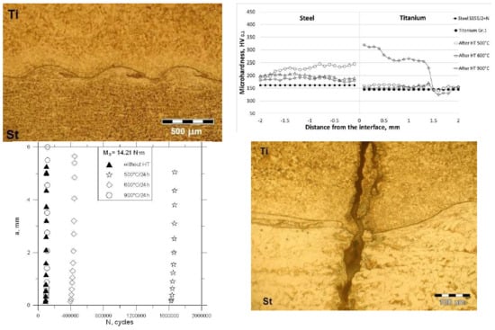
3.1. Microhardness Analysis

The results of micro-hardness measurements for different temperatures and times of annealing are shown in Figure 4. The greatest changes in micro-hardness are observed around the interface where materials were subjected to the large plastic strain due to high velocity of collision during explosive welding. The micro-hardness of the base materials (before cladding) is constant and amounts to 162 HV0.1 for steel, and 145 HV0.1 for titanium. In the case of titanium, the use of heat treatment in the temperature range of 500 to 600 °C does not cause major changes in micro-hardness. The highest micro-hardness values were noted for titanium after annealing at the temperature of 900 °C. However, the tendency of changes in the micro-hardness of steel is the reverse of that for titanium and the micro-hardness is highest at 500 °C, while for the temperature of 900 °C, the micro-hardness is the smallest. The heat treatment of bimetal at the temperature of 500 °C in steel causes the hardness to increase up to 245 HV0.1 (Figure 4a). After 24 h of annealing, the temperature increases and the micro-hardness increases for titanium and decreases in the case of steel. After 2 hours of annealing at the temperature of 900 °C in steel, and at the temperature of 500 and 600 °C in titanium, a decrease in micro-hardness compared to the basic materials is observed. The cause for this behavior is different temperatures of recrystallization and allotropic transformation in steel and titanium. At the interface, after 2 h of annealing, in steel, the micro-hardness stabilizes. This is mainly due to the fact that the structure shows decarburization (a gradual decrease in the amount of perlite and increase in the amount of ferrite).

3.2. Fatigue Crack Growth and Metallography

During fatigue tests, successive increments of crack lengths were measured and the number of cycles was registered. Figure 5 presents an example of crack lengths for the tested clad and various heat treatment temperature and times versus the number cycles. The specimens without heat treatment (HT) and after annealing at 900 °C have the lowest fatigue life. After annealing at the temperature of 500 °C for 2 and 24 h, these specimens showed the highest fatigue life. In Figure 5 it can be seen that the change of the annealing time from 2 to 24 h causes an almost fourfold increase in fatigue life for the temperature of 500 °C. During annealing for 24 h at 500 °C, the life was higher than for 2 h, because the steel was recrystallized. The longer the recrystallization period, the greater the possibility of restoring the deformed metal’s correct crystal structure. The growth of cracking perpendicular to the specimen axis in both steel and titanium was observed (Figure 6). The development of a crack along the interface line was also noticed for the annealing temperature of 600 °C, 900 °C and a 2 h duration as well as 24 h (see Figure 7 and Figure 8). During fatigue tests, it was noticed that the crack was initiated in steel and propagated inside the material towards the interface. For specimens with a large melted layer, initiation of cracks at the break of the wave (Figure 6a) was also observed.
The features of the plastic fracture and brittle fracture around the melted layer in both parts of the clad were noticed. In Figure 6a cracks in the brittle intermetallic phase (at the break of wave) that could have been formed at the time of welding (residual stresses [24]) were observed. Heat treatment of bimetal at the temperature of 500 °C does not result in considerable changes in the microstructure of steel (St) and titanium (Ti). However, a significant increase in fatigue life is observed compared to the bimetal without heat treatment.
In steel, the use of heat treatment causes recrystallization (at the temperature of 600 °C) and normalization (at the temperature of 900 °C), which causes grain growth (Figure 8). Microstructure observations revealed local melting zones at the interface. In the steel layer, decarburization occurred near the interface line (Figure 7). However, in the titanium layer, recrystallization caused by the heat treatment appeared (Figure 8). During recrystallization, the grain growth is dependent on the degree of crushing in the areas of the weld. When the temperature in the joint zone increases, the micro-hardness of the steel decreases, while for titanium the micro-hardness increases as a result of the diffusion of carbon from steel to titanium (Figure 4).
In the vicinity of the interface, the formation of hard and brittle titanium carbides is observed. The occurrence of black inclusions on the grain boundaries in titanium is visible (Figure 8b).
Specimens for EDS tests were ground and then polished on a MoPao polisher. The next step was to place the specimens in the scanning microscope chamber and perform metallographic observation of the specimens. During the observation, the parameters of the microscope were set for the best visibility of the joint. Then, using the analysis program with JOEL, the measurement of the elements (Ti and Fe) in the cross-section of the joint was initiated, as shown in Figure 9.
Measurement points for the EDS analysis were presented in Figure 9. A specimen annealed at 500 °C for 2 h was selected for the tests, because of its highest fatigue life with this annealing time. The black spots shown in Figure 9 in the vicinity of the interface are voids formed in the material.
In order to determine the chemical composition in the vicinity of the interface surface (Figure 10) EDS analysis was performed. Figure 10 compares the amount of Ti at point A (steel) and the amount of Fe at point B (titanium) at the same distance from the interface line. A three times higher share of Fe in titanium than in Ti in steel was observed. This result may indicate the diffusion of carbon to titanium. The results shown in Figure 10 indicate that the diffusion of elements occurred near the interface, and the metal atoms were mixed in the bonding zones. Understanding of the causes for the diffusion of elements should be sought for large plastic strains and the change of the element concentration gradient during the explosive welding.

4. Conclusions

On the basis of the tests of the steel-titanium bimetal subjected to cyclic bending, it can be concluded that:
  • There was a clear relationship between temperature and time of heat treatment and the growth of fatigue cracks. As the annealing temperature increased, the fatigue life decreased. Also for a given annealing temperature, the longer annealing time, the higher the fatigue life.
  • The heat treatment temperature has a significant effect on the distribution of the micro-hardness of the clad. The highest micro-hardness occurs in the bond zone on the titanium side.
  • The temperature increase changes the metallographic structure bimetal. As the heat treatment temperature increases, recrystallization and grain growth (mainly in titanium) are observed. In steel, decarburization was observed to occur at the interface.

Author Contributions

Conceptualization, D.R.; Formal analysis, D.R. and G.K.; Investigation, D.R. and G.K.; Methodology, D.R.; Writing—original draft, D.R.

Conflicts of Interest

The authors declare no conflict of interest.

References

  1. Crossland, B. Explosive Welding of Metals and its Application; Oxford University Press: New York, NY, USA, 1982. [Google Scholar]
  2. Deribas, A.A.; Kudinov, V.M.; Matveenko, F. Effect of initial parameters on process of wave formation in 683 explosive welding. Combust. Explos. Shock Waves 1967, 3, 344–348. [Google Scholar] [CrossRef]
  3. Xie, M.X.; Shang, X.T.; Zhang, L.J.; Bai, Q.L.; Xu, T.T. Interface characteristic of explosive-welded and hot-rolled TA1/X65 bimetallic plate. Metals 2018, 8, 159. [Google Scholar] [CrossRef]
  4. Xie, M.X.; Zhang, L.J.; Zhang, G.F.; Zhang, J.X.; Bi, Z.Y.; Li, P.C. Microstructure and mechanical properties of CP-Ti/X65 bimetallic sheets fabricated by explosive welding and hot rolling. Mater. Des. 2015, 87, 181–197. [Google Scholar] [CrossRef]
  5. Szachogluchowicz, I.; Sniezek, L.; Hutsaylyuk, V. Low cycle fatigue properties of AA2519–Ti6Al4V laminate bonded by explosion welding. Eng. Fail. Anal. 2016, 69, 77–87. [Google Scholar] [CrossRef]
  6. Prażmowski, M.; Rozumek, D.; Paul, H. Static and fatigue tests of bimetal Zr-steel made by explosive welding. Eng. Fail. Anal. 2017, 75, 71–81. [Google Scholar] [CrossRef]
  7. Prażmowski, M.; Paul, H. The effect of stand-off distance on the structure and properties of zirconium—Carbon steel bimetal produced by explosion welding. Arch. Metall. Mater. 2012, 57, 1201–1210. [Google Scholar] [CrossRef]
  8. Rozumek, D.; Marciniak, Z. Fatigue tests of bimetal zirconium-steel made by explosive welding. Procedia Eng. 2016, 160, 137–142. [Google Scholar] [CrossRef]
  9. Banker, J. Advances in Explosion Welding. The Handbook of Advanced Welding; Woodhead Publishing Ltd.: London, UK, 2004. [Google Scholar]
  10. Prażmowski, M.; Paul, H.; Żok, F. The effect of heat treatment on the properties of zirconium-carbon steel bimetal produced by explosion welding. Arch. Metal. Mater. 2014, 59, 1143–1149. [Google Scholar] [CrossRef]
  11. Mousavi, S.A.A.; Al-Hassani, S.T.S.; Atkins, A.G. Bond strength of explosively welded specimens. Mater. Des. 2008, 29, 1334–1352. [Google Scholar] [CrossRef]
  12. Mousavi, S.A.A.; Farhadi, S.P. Experimental investigation of explosive welding of cp-titanium/AISI 304 stainless steel. Mater. Des. 2009, 30, 459–468. [Google Scholar] [CrossRef]
  13. Deribas, A.A.; Kudinov, V.M.; Sobolenko, T.M. Shock hardening of low-carbon steel plates at variable impact angle. Combust. Explos. Shock Waves 1967, 3, 424–431. [Google Scholar] [CrossRef]
  14. Gloc, M.; Wachowski, M.; Plocinski, T.; Kurzydlowski, K.J. Microstructural and microanalysis investigations of bond titanium grade1/low alloy steel st52-3N obtained by explosive welding. J. Alloys Compd. 2016, 671, 446–451. [Google Scholar] [CrossRef]
  15. Rao, N.V.; Reddy, G.M.; Nagarjuna, S. Structure and properties of explosive clad HSLA steel with titanium. Trans. Indian Inst. Metals 2014, 67, 67–77. [Google Scholar]
  16. Nishida, M.; Chiba, A.; Honda, Y.; Hirazumi, J.I.; Horikiri, K. Electron microscopy studies of bonding interface in explosively welded Ti/steel clads. ISIJ Int. 1995, 35, 217–219. [Google Scholar] [CrossRef]
  17. Karolczuk, A.; Kowalski, M.; Bański, R.; Zok, F. Fatigue phenomena in explosively welded steel-titanium clad components subjected to push-pull loading. Int. J. Fatigue 2013, 48, 101–108. [Google Scholar] [CrossRef]
  18. Sniezek, L.; Szachogluchowicz, I.; Wachowski, M.; Torzewski, J.; Mierzynski, J. High cycle fatigue properties of explosively welded laminate AA2519/AA1050/Ti6A14V. Procedia Struct. Integr. 2017, 5, 422–429. [Google Scholar] [CrossRef]
  19. Rozumek, D.; Bański, R. Crack growth rate under cyclic bending in the explosively welded steel/titanium bimetals. Mater. Des. 2012, 38, 139–146. [Google Scholar] [CrossRef]
  20. Rozumek, D.; Hepner, M. Influence of microstructure on fatigue crack propagation under bending in the alloy Ti-6Al-4V after heat treatment. Mat. Wiss. Werkstofftech. 2015, 46, 1088–1095. [Google Scholar] [CrossRef]
  21. Rozumek, D.; Marciniak, Z. The investigation of crack growth in specimens with rectangular cross-sections under out-of-phase bending and torsional loading. Int. J. Fatigue 2012, 39, 81–87. [Google Scholar] [CrossRef]
  22. Lewandowski, J.; Rozumek, D. Cracks growth in S355 steel under cyclic bending with fillet welded joint. Theor. Appl. Fract. Mech. 2016, 86, 342–350. [Google Scholar] [CrossRef]
  23. Walczak, W. Explosive Welding of Metals; WNT: Warsaw, Poland, 1989. [Google Scholar]
  24. Karolczuk, A.; Paul, H.; Szulc, Z.; Kluger, K.; Najwer, M.; Kwiatkowski, G. Residual Stresses in Explosively Welded Plates Made of Titanium Grade 12 and Steel with Interlayer. J. Mater. Eng. Perform. 2018, 27, 4571–4581. [Google Scholar] [CrossRef]
Figure 1. The two-layered set system, where: 1—detonator, 2—explosive material, 3—clad material, 4—base material, 5—sandy ground, H—High explosive material, g1—high technological distance, t1—thickness clad material, t2—thickness base material.
Metals 09 00338 g001
Figure 2. The zone of steel-titanium clad joint.
Metals 09 00338 g002
Figure 3. Shape and dimensions of specimens, dimensions in mm.
Metals 09 00338 g003
Figure 4. Micro-hardness measurements of a steel-titanium connection for different temperatures and times annealing: (a) 2 h, (b) 24 h.
Metals 09 00338 g004
Figure 5. Fatigue crack length vs number of cycles N for heat treatment after: (a) 2 h, (b) 24 h, and (c) 500 °C.
Metals 09 00338 g005
Figure 6. Microstructure and cracks observed in the specimens after the heat treatment at the temperature of 500 °C and: (a) 2 h, (b) 24 h.
Metals 09 00338 g006
Figure 7. Microstructure and cracks observed in the specimens after the heat treatment at the temperature of 600 °C and: (a) 2 h, (b) 24 h.
Metals 09 00338 g007
Figure 8. Microstructure and cracks observed in the specimens after the heat treatment at the temperature of 900 °C and: (a) 2 h, (b) 24 h.
Metals 09 00338 g008
Figure 9. Microstructure of bimetal with measuring points.
Metals 09 00338 g009
Figure 10. Energy spectrum analysis for a specimen after a heat treatment of 500 °C and 2 h from Figure 8 for: (a) A, (b) B.
Metals 09 00338 g010
Table 1. Chemical composition of experimental materials (wt %).
MaterialsChemical Composition (≤%)
S355J2 + NCMnSiPSCuNiCrMoVAlNbFe
0.191.410.300.010.030.230.030.050.040.030.030.003Bal.
Ti Gr.1CFeHONTi
0.10.20.010.180.03Bal.
Table 2. Static mechanical properties of analyzed materials before cladding.
Materialsσu (MPa)σy (MPa)E (GPa)ν
S355J2 + N5783682100.3
Ti Gr.13081931040.37
Table 3. Characteristic parameters of the joint steel-titanium.
Temp. HT (°C)/Time (h)Average Wave-Length (μm)Average Wave-Height (μm)Value of ETR (μm)Detonation Velocity (m/s)
Without HT217411.52200
500/2211251819.63000
600/2225248050.13000
900/2221446246.23000
500/24843993.02200
600/24781793.12200
900/24822923.12200

