Article

On the Development Concept for a New 718-Type Superalloy with Improved Temperature Capability

1
Technische Universität Braunschweig, Institut für Werkstoffe, Langer Kamp 8, D-38116 Braunschweig
2
VDM Metals International GmbH, Plettenberger Straße 2, D-58792 Werdohl, Germany
3
VDM Metals International GmbH, Kleffstraße 23, D-58762 Altena, Germany
*
Author to whom correspondence should be addressed.
Metals 2019, 9(10), 1130; https://doi.org/10.3390/met9101130
Submission received: 22 August 2019 / Revised: 14 October 2019 / Accepted: 15 October 2019 / Published: 22 October 2019

Abstract

:
The superalloy 718 stands out for its excellent manufacturability and strength at ambient temperature. However, its application temperature is limited to about 650 °C due to the instability of the γ″ precipitates. Here, we provide an in-depth account of an alloy development concept, allowing for the design of superalloys with 718-type properties, yet with a significantly improved microstructural stability. The article begins with a detailed discussion on how the microstructural and chemical composition must be altered to achieve this objective. Then, model alloys were used to explore and validate the outlined strategy. Finally, it is shown how these considerations ultimately led to a new 718-type superalloy with far more improved microstructural stability— namely, VDM Alloy 780. The introduction of a large amount of Co as a substitute for Fe (and partially Ni) is the most important element of our alloy development concept in terms of chemical composition. The most important microstructural feature is the introduction of low solvus temperature, high misfit γ′-strengthening, replacing γ″-hardening.

1. Introduction

Alloy 718, developed in the 1950s with the respective patent filed in 1958 [1], remains the most widely used Ni-based superalloy to date. As mentioned by Eiselstein [2], the original intent at that time was the development of a Ni-based solid solution-strengthened alloy with niobium being one of the investigated alloying elements. In the course of this work, an outstanding age hardening response was noted in the case of Nb addition, leading eventually to alloy 718. As is well known today, sufficiently high amounts of Nb in combination with relatively small amounts of the γ′ formers Al and Ti lead to the precipitation of the γ″-phase of the Ni3Nb type (Strukturbericht designation D022). Its large lattice parameter misfit to the γ-matrix is responsible for the high strength of the alloy despite a moderate precipitate content of about 21% after extended aging at 700 °C [3]. Even though alloy 718 also contains some amount of γ′, the principal strengthening phase is γ″. Besides its excellent strength and ductility, a key feature of alloy 718 is its sluggish precipitation kinetics, see the time–temperature transformation diagrams for alloy 718 [3,4]. This leads to excellent weldability and manufacturability of large wrought and cast components simply because the alloy remains in a soft state during processing, so that large internal stresses cannot build up.
A third precipitate phase present in alloy 718 is the δ-phase (Strukturbericht designation D0a), which is the thermodynamically stable variant of the metastable γ″-phase. Necessarily, its solvus temperature exceeds that of the γ″-phase, which is about 1000 °C in alloy 718 [3,4]. Due to the relatively large nucleation barrier, the δ-phase typically precipitates heterogeneously at grain boundaries. Especially in combination with hot working and concomitant recrystallization, it tends to form blocky particles there with a few micrometers in size. However, it may also grow in the form of plates into the grain interior with a (010)δ || {111}γ, [100]δ || <110>γ orientation relationship [5]. While the δ-particles are too large to cause strengthening, they are small enough to cause sufficient Zener drag for effective grain boundary pinning. This leads to a further advantage of alloy 718: if the material is hot deformed above the solvus temperature of the strengthening phases but below the solvus temperature of the δ-phase, it is in a soft state. Nevertheless, a small grain size of ten micrometers and less can be attained due to the presence of the δ-phase. This is especially beneficial for turbine disc applications, as a small grain size significantly improves fatigue strength and examinability by ultrasound. The situation is quite different in the case of conventional γ′-strengthened wrought superalloys like Waspaloy or Udimet 720. Here, large γ′ particles obtained by sub-solvus heat treatment must be used for grain size control [6]. The drawback is that slight temperature excursions during processing lead either to γ′ dissolution (i.e., large grains) or a severe reduction of deformability due to additional γ′ formation and concomitant strengthening. This makes fine grain forging a tedious and costly endeavor.
Despite these advantages there is, however, one major drawback of alloy 718. As γ″ is a metastable phase, microstructural stability is limited. Extended exposure above approximately 650 °C leads to the transformation of γ″ to the thermodynamically stable δ-phase, now precipitating in the grain interior in the form of large plates with the above given orientation relationship to the γ-matrix. Consequently, γ″ strengthening is lost, rendering the material unsuitable for applications beyond about 650 °C [7]. Given this situation and the ever-increasing demand for materials with improved temperature capability in gas turbine applications, a 718-type material with improved temperature capability would be highly beneficial. As the advantageous features of high strength and slow precipitation kinetics are linked to the γ″-phase as mentioned above, the aim of past alloy development efforts was mainly to maintain this phase. Tien and coworkers concentrated on the (Al+Ti)/Nb and Al/Ti ratios while leaving the concentration of the remaining elements essentially as so in alloy 718 [8,9]. They demonstrated that γ′/γ″ microstructures can be maintained at higher (Al+Ti)/Nb and Al/Ti ratios compared to that in alloy 718. As the ratio of γ′ to γ″-content increases by these measures, the transformation of γ″ to δ becomes more sluggish, thus improving the microstructural stability compared to alloy 718. It was also noticed that these measures reduce the fraction of δ-phase nucleating along grain boundaries [8]. Fundamentally, this is an unwanted effect as the δ-phase is needed to ensure fine grain forging. In Reference [8], the investigated compositional range for Al, Ti, and Nb was 0.46–0.87%, 0.95–1.41%, and 4.32–5.67%, i.e., close to the typical specification limits of alloy 718 (all chemical compositions are given in wt.% unless otherwise stated). Similar efforts to improve the microstructural stability, primarily by increasing the (Al+Ti)/Nb ratio have also been made by other authors [10].
Mignanelli et al. [11] investigated the role of the Al/Nb ratio on the stability of the γ′/γ″-phases, suggesting an atomic ratio between 0.3 and 1.0 for the formation of microstructures containing both precipitate phases in comparable quantities. Based on these findings, they report on the alloy Ni–13.3Cr–1.85Al–9.53Nb, having stable γ′/γ″ precipitates after thermal exposure at 700 °C/1000 h, i.e., a microstructural stability superior to that of alloy 718. As in Reference [8], the results suggest that the microstructural stability increases with the γ′/γ″ ratio even though the total contents of precipitate forming elements were quite different in these studies.
With ATI 718Plus®, a 718-type alloy was developed containing predominantly γ′ as the strengthening phase [7]. Essential compositional differences to alloy 718 are a reduced Fe content (10% instead of 18%), addition of 9% Co, an increased amount of Al (1.45% instead of 0.45%), and a slightly reduced Ti content (0.7% instead of 1.0%). It is emphasized that a higher Al/Ti ratio and an increased sum of Al+Ti are required to achieve the alloy development objective of a 55 °C improvement in temperature capability compared to alloy 718. The best mechanical properties were found at an Al/Ti ratio and Al+Ti content of 4 and 4%, respectively (obtained from the chemical composition in at.%) [7]. It is also stated that the selected Co content improves the mechanical properties and thermal stability. The ability of Co to reduce the stacking fault energy is mentioned in this context. Initially, it was thought that the high-temperature phase for grain refinement is the δ-phase with a D0a crystal structure [12]. More recent analysis suggests an ordered type of the η-phase (Strukturbericht designation D024) with Ni6AlNb stoichiometry [13] and/or a layered structure within individual particles, consisting of η and δ [14]. Note that η- and δ-phase can be used alike for grain refinement. Alloy 706 is a well-known example where η-phase is utilized for that purpose.
There were also efforts to develop classical γ′-strengthened wrought superalloys with improved weldability and manufacturability compared to Udimet 720Li, a widely used wrought γ′-strengthened superalloy for disc applications. Examples include the development of the alloys AD730TM [15] and René 65 [16]. However, these alloys lack a fundamental advantage of 718-type alloys, namely, the non-strengthening high-temperature phase for ease of grain refinement.
Recently, a 718-type superalloy aiming at an even higher temperature capability than ATI 718Plus®, approximately +100 °C compared to alloy 718, was developed collaboratively between the Technische Universität Braunschweig and VDM Metals GmbH [17,18,19]. Currently, this alloy is in the phase of market introduction under the trade name VDM Alloy 780. In this article, we provide a full account of the development concept behind this work.
The article is structured as follows: In Section 2.1, basic considerations regarding the precipitation kinetics of the γ′- and γ″-phases are provided and the strategy for the development of 718-type superalloys with improved microstructural stability is established. We will qualitatively deduce the required changes with respect to the chemical composition and microstructure to attain the development objective. Then, systematic chemistry modifications along with microstructure analysis and thermodynamic calculations are conducted in Section 2.2 to explore and proof the alloy development strategy, leading finally to VDM Alloy 780.
A Zeiss Leo 1550 scanning electron microscope was used for microstructural analysis. Secondary electron (SE) and in-lens detectors were used as indicated in the figure captions. A V2A-etchant (200 mL H2O, 200 mL HCl, 20 mL HNO3, 0.6 mL Vogels Sparbeize), which preferentially leaches the matrix, was used to reveal the microstructure. The HV10 Vickers hardness testing was conducted on a A Leco LV 100AT hardness tester.

2. Alloy Development

2.1. Basic Considerations and Development Strategy

Clearly, developing an alloy with 718-type properties but with a significantly improved microstructural stability for service at temperatures beyond 650 °C is a difficult task. This is reflected in the fact that the amount of commercially available alloys achieving this requirement is sparse despite considerable research. For long, the γ″-phase was considered essential to fulfill the requirements for strength in combination with sluggish precipitation characteristics, i.e., good manufacturability. However, as mentioned, this phase is metastable, and it is understandable that the improvements in temperature capability are limited as long as this phase is used as the essential strengthening phase. Thus, it seems worthwhile to revisit these considerations regarding the γ″-phase. Concentrating on precipitation kinetics first, there are a number of essential factors controlling the speed of precipitation processes. Firstly, the solvus temperature of the precipitate phase matters. If it increases, also the onset of precipitation is shifted to higher temperatures. This leads then to faster diffusion, i.e., faster precipitation kinetics. The effect is quite dramatic. Taking the activation energy for self-diffusion of nickel (i.e., 284 kJ/mol [20]) as a reasonable approximation for diffusion processes in superalloys and assuming precipitation at 900 °C instead of 800 °C, the diffusion kinetic is accelerated by a factor of 15. Thus, one intent of any effort to develop a 718-type alloy with sluggish hardening response must be to limit the solvus temperature of the phase leading to precipitation strengthening. Secondly, the diffusivity of the elements forming the precipitates is of concern. If one could select elements with particularly low diffusion coefficients, it would be possible to slow down the precipitation kinetics. Al, Ti and Nb are the essential elements to form γ′ and γ″ in wrought superalloys. In Reference [21], the diffusion coefficient of Al in Ni is given as DAl = 1.4 × 10⁻⁴ (m2/s)·exp[−263 (kJ/mol)/RT]. The data for the lowest given Al concentration of 1.0% were used, as this amount well reflects typical concentrations in 718-type alloys. The diffusion coefficient of Nb in Ni is DNb = 8.8 × 10⁻⁵ (m2/s)·exp[−257 (kJ/mol)/RT] [22]. Taking 800 °C as an example, DAl = 2.2 × 10⁻¹⁷ (m2/s) and DNb = 2.7 × 10⁻¹⁷ (m2/s) result, demonstrating very similar diffusivities. Furthermore, investigation of diffusivities in the ternary Ni–Al–Ti system shows similar diffusivities of Al and Ti in nickel [21]. Data for Al and Ti in binary Ni–X systems [23] suggest a slightly faster diffusion of Al than Ti by a factor of about 1.6 at T ≥ 1200 °C. Thus, it is noted that the diffusivities of these three elements are very similar. In this respect, there is no reason for the Nb-rich γ″ phase to precipitate more slowly than the Al-rich γ′-phase. A third aspect relates to the interface energy. As it increases, the nucleation barrier at a given chemical driving force increases and the nucleation process slows down. The interface energy of γ″ in alloy 718 was determined as 95 mJ/m−2 [24]. The interfacial energies of the γ′-particles were examined by Li et al. [25]. According to their literature analysis, values between 6 and 80 mJ/m−2 have been found in binary Ni–Al alloys. However, they also point out that γ′-interface energies in superalloys tend to be higher, giving a range between 58 and 91 mJ/m−2 for a number of superalloys. These values come close to the value reported for γ″ in alloy 718. In summary, none of these aspects yield a fundamental reason for the γ′-phase to necessarily precipitate much faster than the γ″-phase at a given solvus temperature. However, it is well known that the solvus temperature of the γ″-phase in alloy 718 is considerably lower than that of the γ′-phase in comparable γ′-strengthened superalloys such as Waspaloy and Udimet 700. While the former is about 930 °C [3,4], the Tγ′,solvus in Waspaloy and Udimet 700 is about 1050 °C and 1135 °C, respectively [26]. This appears to be the main reason for the slower precipitation kinetics of the γ″-phase in alloy 718. To study these differences, we conducted Jominy end-quench tests according to DIN EN ISO 642, using rods with a 25 mm diameter and 100 mm length. The heat treatment protocols before quenching were 980 °C/1 h and 1080 °C/1 h for alloy 718 and Waspaloy, respectively, ensuring complete dissolution of the strengthening phase. After the water quenching of one circular end, the hardness was measured as a function of the distance from this end and the results are plotted in Figure 1a. Clearly, the differences are drastic. In the case of Waspaloy, the hardness increased immediately with the distance from the quenched end, demonstrating that γ′ precipitation takes place even close to the quenched end. At a distance of 20 mm and above, a hardness of about 400 HV10 was reached. Actually, this value is larger than the hardness after a typical solution and precipitation heat treatment. For example, 1080 °C/4 h/AC + 845 °C/24 h/AC + 760 °C/16 h/AC (AC: air cooling) yields a hardness of 361 HV10. In contrast, the hardness of alloy 718 remains essentially constant over the entire sample length. The measured value is essentially that of the solution heat-treated alloy. Thus, there is no γ″ precipitation at all. In this context, it is noteworthy that the precipitate content of both alloys is not too different. It is about 21% in the case of alloy 718, as mentioned above, and about 24% in Waspaloy [27,28].
Due to these considerations, it was concluded here that the need for sluggish precipitation does not necessarily require γ″ strengthening. Furthermore, no reasonable measure was seen to ensure the long-term stability of the γ″-phase at service temperatures as high as 750 °C. For this reason, the focus was on the development of an alloy with 718-characteristics yet containing γ′ for strengthening along with the δ-phase for grain size control during processing. The key task was then to find a means to combine a sufficiently low solvus temperature of the γ′-phase for control of the precipitation kinetics with a sufficiently high γ′ content at service temperature for strengthening. In this respect, cobalt was identified as a promising alloying element. It not only diminishes Tγ′,solvus. It also reduces the solubility of the γ′ forming elements at typical operation temperatures, thus increasing the γ′ content for a given amount of γ′-forming elements in the temperature range where it is required [29]. This double effect appears to be ideally suited for the alloy development objective at hand. For this reason, all alloy compositions investigated here contained significant amounts of Co, replacing Fe and, to a certain extent, Ni. As will become apparent in Section 2.2, Co has a third beneficial effect—it also stabilizes the δ-phase. This is very important because Al, required for γ′ precipitation, has a destabilizing effect on the δ-phase. Therefore, one would lose the δ-phase if one simply increased the Al content while otherwise maintaining the composition of alloy 718. Furthermore, it is clear that the solvus temperature of the strengthening phase must be below the solvus temperature of the phase used for grain size control during processing. Otherwise, fine grain forging would not be possible in a soft material state. For this reason, sufficient stability of the δ-phase must be ensured. Apart from these benefits of Co specific to the alloy development objective at hand here, Co also improves the creep strength by lowering the stacking fault energy as an additional advantage.
In addition to the Co effect, there is another potential measure to keep Tγ′,solvus under control: to achieve the strength level of alloy 718, a certain strengthening contribution by the γ′-phase is required. The γ′ volume fraction needed for this purpose depends on the γ/γ′ misfit. With increasing misfit, the required γ′ content (i.e., required amount of γ′-forming elements) decreases. This leads then to a lower γ′ solvus temperature at given Co content. Thus, a further alloy development objective must be to ensure a relatively large γ/γ′ misfit. Of course, increasing the misfit will reduce the critical particle radius at which coherency is lost, making the γ′ precipitates less stable in this respect. However, the intended application temperature here is moderate compared to the requirements for blade alloys. For this reason, no negative side effect is expected when the misfit is raised. In this context, it appears worthwhile to inspect some misfit values. Taking aγ = 0.3598 nm and aγ″ = 0.3630 nm, measured after heat treatment of alloy 718 at 750 °C/4 h [30], as relevant parameters, an unconstrained misfit of 0.89% results in the case of alloy 718. In contrast, a value of 0.02% was reported in the case of Udimet 700 [31]. For Waspaloy, aγ = 0.35768 nm and aγ′ = 0.35904 lead to an unconstraint misfit of 0.38% [28]. Constrained values reported for Udimet 720 and a number of Nimonic alloys were in the range of −0.04% to +0.34% [32]. Thus, the misfit of Waspaloy appears to be on the upper end for currently available wrought γ′-strengthened superalloys.
From these considerations, two requirements for fundamental deviations from the chemical composition of alloy 718 can be deduced. Firstly, a high Co content is required, replacing Fe, and, to a certain extent, Ni. Secondly, the Al content must be significantly increased as precipitation strengthening is switched from the γ″-phase to the γ′-phase. Nevertheless, a high Nb content is required because the δ-phase is still wanted for grain size control. Will these measures lead then to a large γ/γ′ misfit? Probably yes. If γ″ is replaced by γ′, Nb will be enriched in the γ′-phase. As Nb is a particularly large atom, it significantly increases the lattice parameter of the γ′-phase [33]. Replacing Fe with Co will reduce the lattice parameter of the γ-matrix at the same time, as Fe increases aγ while Co does not [34,35]. This may lead then to a positive γ/γ′ misfit, being large compared to values otherwise achieved in γ′-strengthened wrought superalloys. However, one should not expect misfit levels as high as in alloy 718, simply because γ′ is Ni3Al-based while γ″ is Ni3Nb-based with Nb consuming more volume than Al in these phases. Results regarding the lattice parameter misfit will be presented in Section 2.2.

2.2. Investigation of Co-Rich Alloys

In order to explore the effect of the aforementioned changes in the chemical composition, model alloys were produced, where the Co concentration varied between 10% and 30% and the amount of the γ′-forming elements Al and Ti was altered. The alloying elements Cr, Mo, and Nb remained at the level of alloy 718 while Fe was completely replaced by Co. Furthermore, 0.025% carbon was added which is a typical content in alloy 718.
Table 1 shows a list of alloys discussed in the following. There are two series of alloys. In the L series, discussed in Section 2.2.1, the amount of Co was varied at a constant Al and Ti content in order to investigate the effect of Co on the microstructure and properties of the alloys. Section 2.2.1 is concluded with a closer inspection of alloy L4. It is demonstrated that this alloy exhibits the intended characteristics, namely presence of the δ-phase for grain refinement as in alloy 718, a slow precipitation kinetics despite presence of the γ′-phase for strengthening, a hardness comparable to that of alloy 718 and, at the same time, an improved microstructural stability compared to alloy 718. This demonstrates the validity of the alloy development concept proposed in Section 2.1. In Section 2.2.2, the question of whether further improvements in the microstructural stability, beyond that of alloy L4, are possible is addressed. For this purpose, the V-alloy series was investigated where the focus was on the Al/Ti ratio at a given Co content. These investigations finally led to alloy V17 which essentially became VDM Alloy 780. The section closes with remarks concerning this new 718-type superalloy.
The alloys investigated here were produced by vacuum arc melting, typically in quantities of 600 g per melt; in the following, this is referred to as laboratory scale, unless otherwise stated. The melt was poured into copper crucibles, leading to rods with a 13 mm diameter and approximately an 80 mm length. The materials were then homogenized in a vacuum furnace at 1140 °C/6 h + 1175 °C/20 h and hot deformed by rotary swaging, leading to a diameter of 9 mm and a true strain of φ = −0.37. Unless otherwise stated, the materials were then heat treated at 980 °C/1.5 h/water quenching (WQ) + 718 °C/8 h + furnace cooling (FQ) at 50 °C/h to 621 °C/8 h; in the following, this is referred to as standard heat treatment. This is a typical solution and precipitation heat-treatment procedure for alloy 718. Additionally, thermodynamic calculations were conducted using the software ThermoCalc®, Version S with a TTNi7 database.

2.2.1. The effect of the Co Content

In the first set of experiments using the L-alloys in Table 1, we were interested in studying the effect of Co on the tendency to form the δ-phase. All micrographs were obtained after standard heat treatment. 
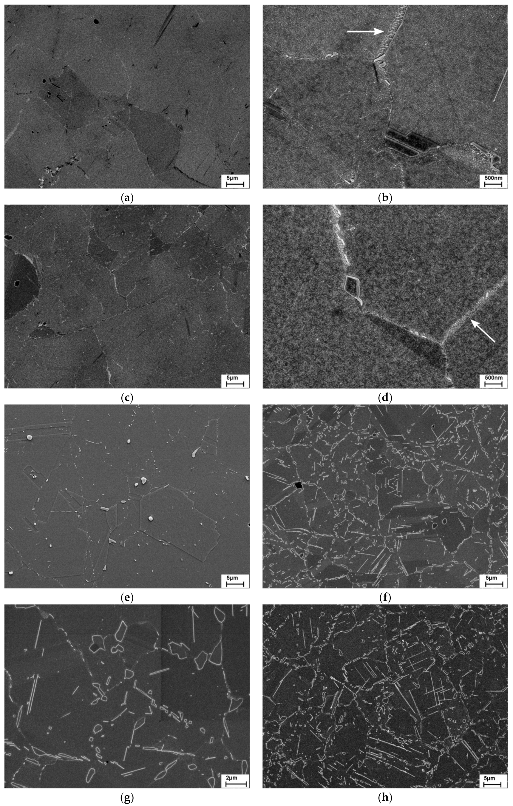
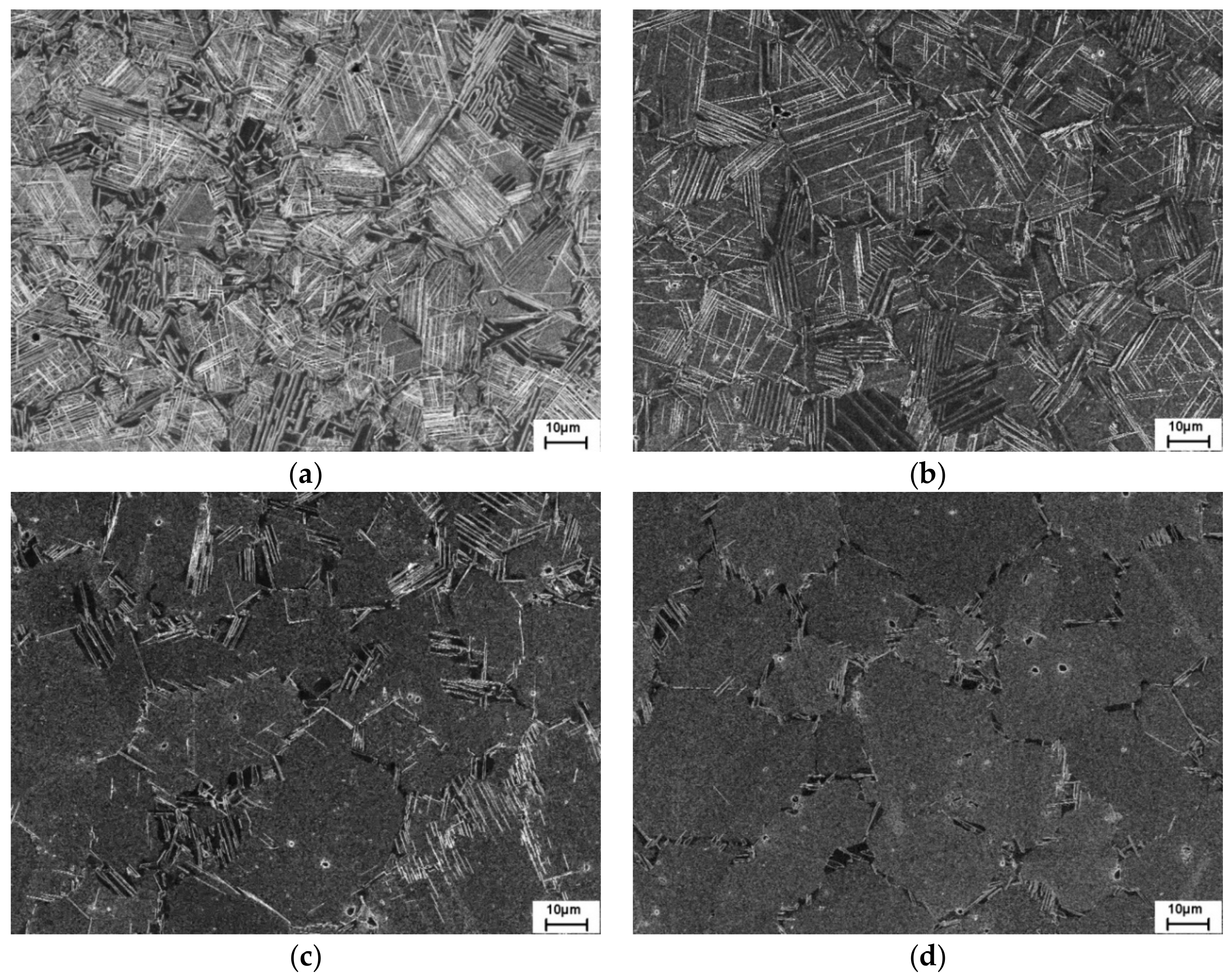
Figure 2 shows a first series of alloys where the Co content varied from 10% to 30% at an Al and Ti concentration of 1.2% and 1.1%, respectively. At low magnification and the lowest Co contents of 10% and 14%, hardly any precipitation at grain boundaries (i.e., the typical precipitation site of the δ-phase) could be seen (Figure 2a,c). In fact, it turns out at higher magnification that most of what can be seen is a discontinuous precipitation reaction of the γ′-phase (see arrows in Figure 2b,d), while very few discrete particles that can be associated with the δ-phase are visible. Probably, the lack of grain boundary pinning by the δ-phase facilitated the discontinuous precipitation reaction. At a Co content of 17% (Figure 2e), δ-phase can clearly be seen at grain boundaries, yet at a relatively small content. In contrast, there was massive precipitation of particles along grain boundaries but also in the grain interior at 25% Co and, particularly, at 30% Co (Figure 2f–i). This clearly shows the effect of Co in promoting the precipitation of larger particles that can be effectively used for pinning of grain boundaries. Interrupted heat treatment experiments demonstrated that these particles form as a result of the heat treatment at 980 °C/1.5 h.
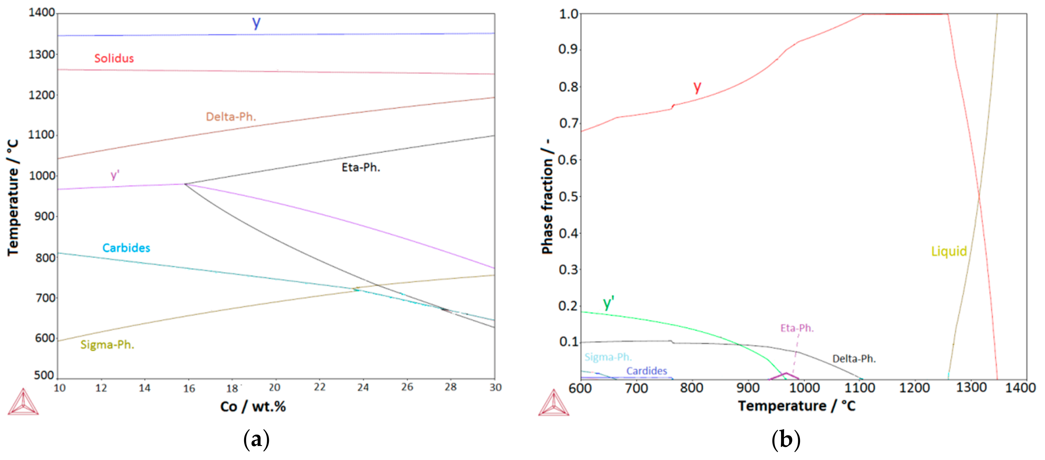
To analyze the effect of Co on phase formation in these superalloys further, a quasi-binary phase diagram was calculated using a varying Co/Ni content at the same amount of C, Cr, Mo, Al, Ti, and Nb, as in the abovementioned alloy series. The result is shown in Figure 3a. It can clearly be seen that Co has a pronounced effect on the stability of the δ-phase in that it significantly increases its solvus temperature. Consequently, the equilibrium volume fraction of the δ-phase at 980 °C increases with the Co content according to the calculations. This prediction is in agreement with the experimental findings. The calculations predict an analogous correlation between Co content and η-phase formation. At 10% and 14% Co, η does not exist and the η-phase field is barely touched at 17%. This is further illustrated in Figure 3b, where the calculated phase fractions are shown for the latter amount of Co. The field of existence of the η-phase is only between approximately 940 °C and 990 °C and the calculated volume fraction is very small. However, significant precipitation of the η-phase at 980 °C is predicted for alloys L17 and L18, containing 25% and 30% Co, respectively. In this context, it is worthwhile to inspect the corresponding micrographs again (Figure 2f–i). They show two particle populations with distinctively different morphologies. One is essentially equiaxed with blocky morphology and the other is in the form of narrow plates with high aspect ratio, respectively. While the δ-phase in alloy 718 is typically blocky after billet forging and subsequent heat treatment at around 980 °C, the η-phase in alloy 706 always forms as narrow plates [37]. Thus, it stands to reason that the former population belongs to the δ-phase while the latter to the η-phase. However, precise phase identification for these model alloys was beyond the scope of this study and the assignment of the two particle morphologies to the δ- and η-phases was conducted with this qualification. Coexistence of both phases in superalloys was also reported in References [38,39].
According to Figure 3a, the solvus temperature of the γ′-phase remains essentially constant as long as the η-phase does not form. Once η forms, Ti is removed from the matrix. Consequently, Tγ′,solvus declines. It is always lower than Tδ,solvus. This is important for practical applications as fine grain forging has to be conducted in the presence of the δ-phase but in the absence of the strengthening phase. The M23C6 carbide occurs due to the small amount of carbon added. According to the calculations, the σ-phase is also present; however, it was never observed experimentally in the investigated alloys.
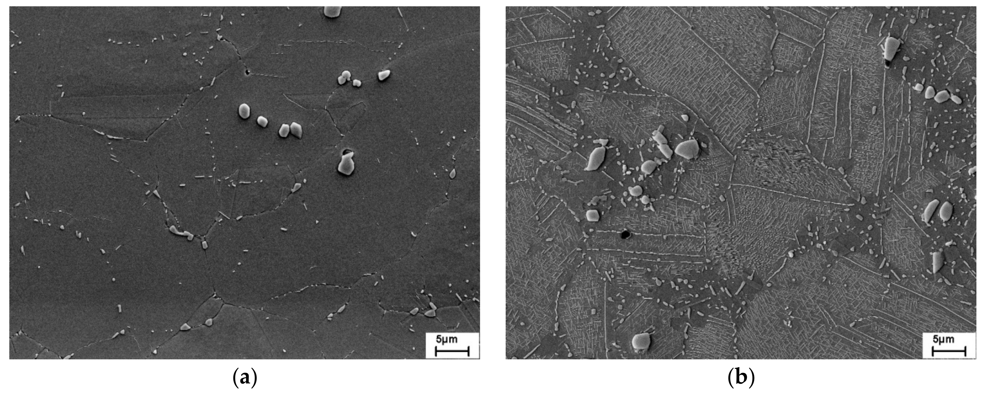
To demonstrate that the aforementioned effect of Co in stabilizing the δ/η-phase is not limited to a specific content of the γ′- forming elements, a further example is given. Here, the Al and Ti content was essentially that of alloy 718, i.e., 0.65% and 0.75%, respectively. While alloy L3, containing 17% Co, showed a small number of particles, being essentially located at grain boundaries (Figure 4a), alloy L6 (30% Co) exhibited massive precipitation of particles at grain boundaries and in the grain interior (Figure 4b). Again, two distinctively different particle morphologies were visible, which may be linked to the δ- and η-phases. Clearly, the Co content must be selected such that sufficient particles are present for grain refinement but excessive δ/η-formation is prevented.
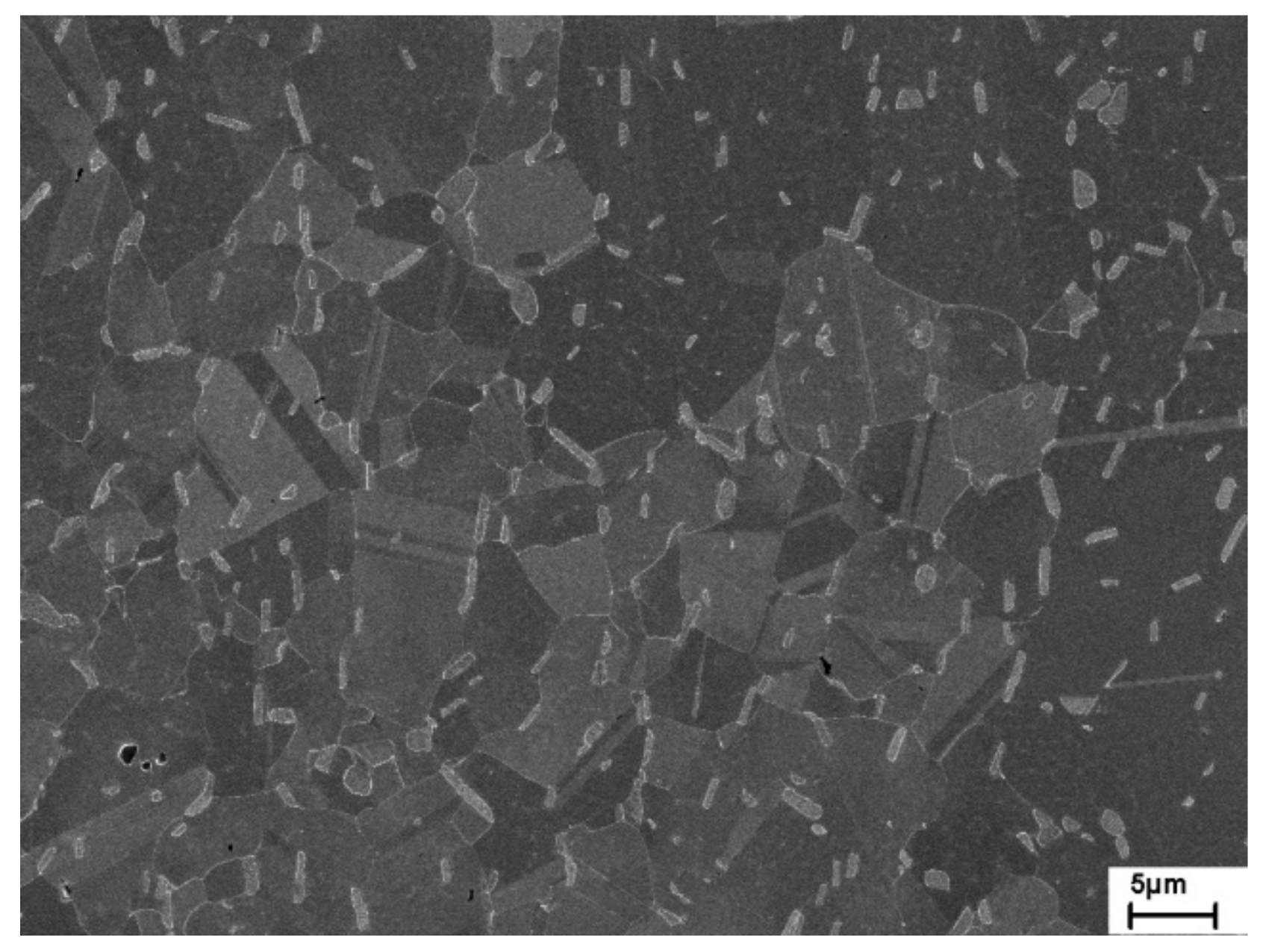
Among the materials investigated thus far, alloy L4 appears to be particularly interesting. It contains a moderate amount of δ-phase and is expected to be predominantly strengthened by the γ′-phase due to the fact of its raised Al content. Hence, this alloy was studied in more detail. For this purpose, it was not only produced on a laboratory scale but also in a larger quantity. Two hundred kilograms were triple melted at the Institut für Metallurgische Prozesstechnik und Metallrecycling, RWTH Aachen and forged at the Institut für Bildsame Formgebung, RWTH Aachen for this purpose. In the following, this processing route is referred to as a technical scale. The microstructure of the forged billet after standard heat treatment is shown in Figure 5. Blocky δ-precipitates are uniformly distributed along grain boundaries. As a result, the grain size is fairly small. The particle morphology and distribution resemble that of alloy 718. Compared to the same material fabricated on a laboratory scale (see Figure 2e), the precipitation was more pronounced. This can be attributed to the higher degree of deformation, promoting the formation of the δ-phase.
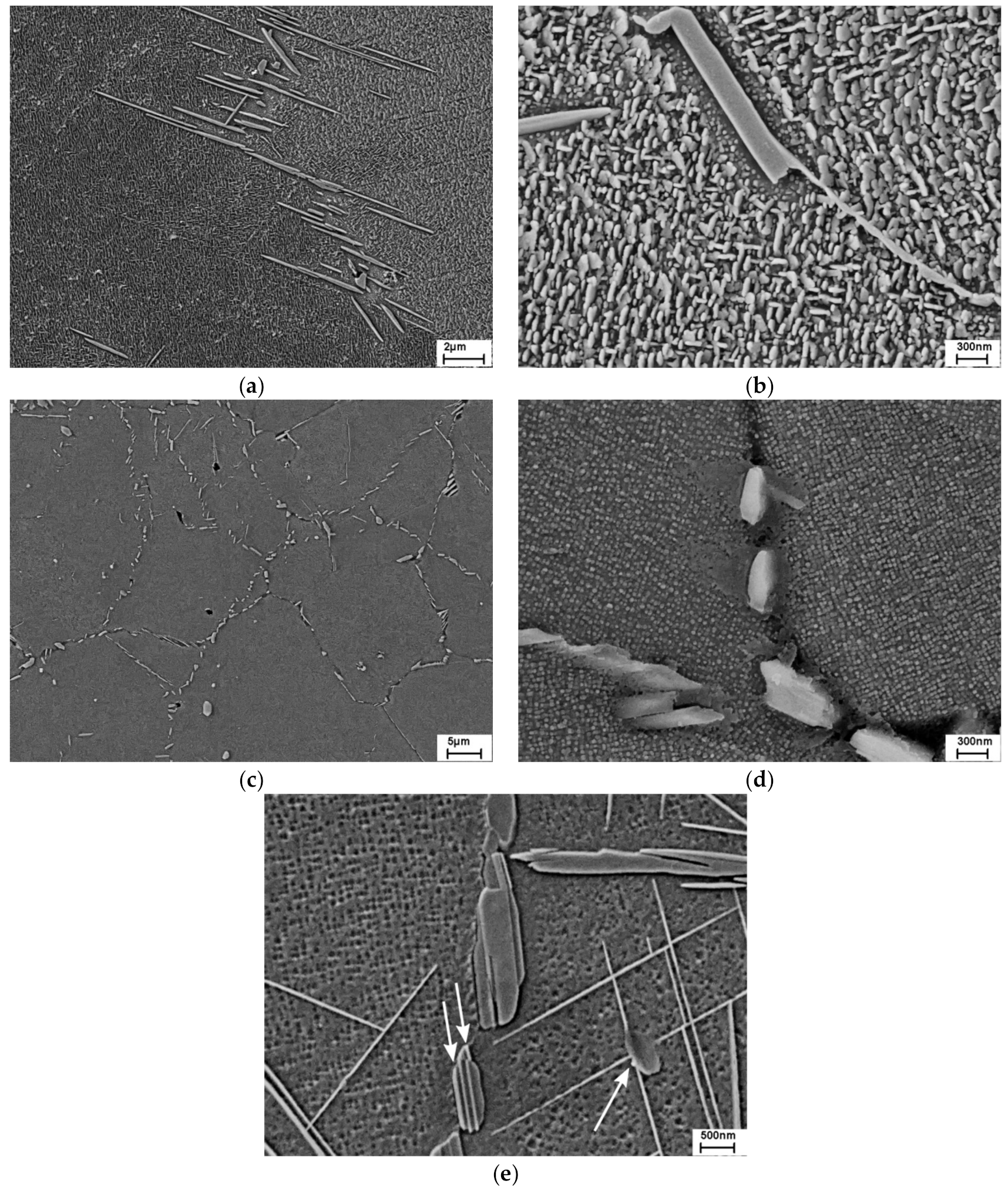
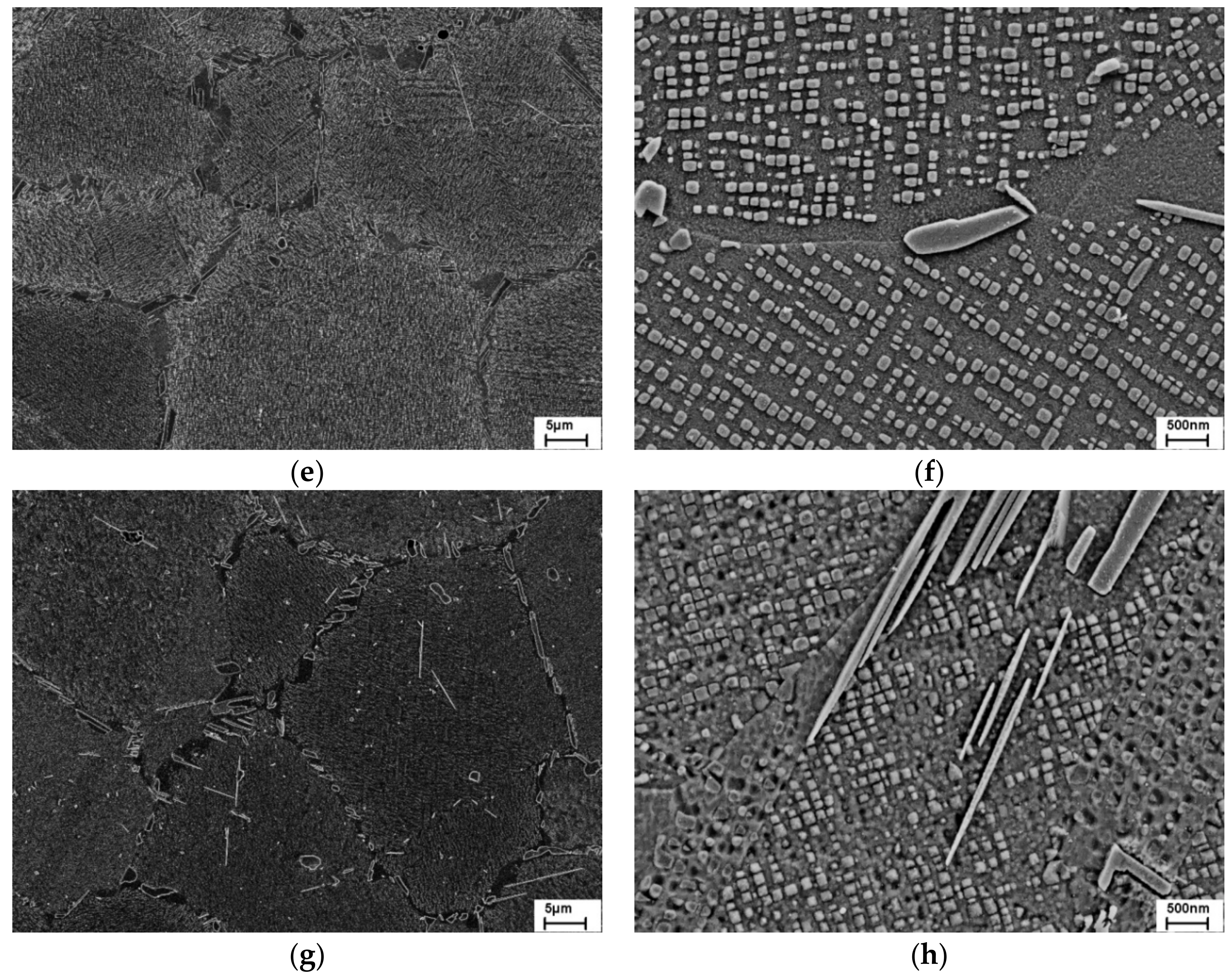
In Figure 6a–d, the microstructure of alloy L4 is compared with that of alloy 718 after standard heat treatment plus aging at 700 °C/500 h. While alloy L4 was produced on a laboratory scale, alloy 718 was produced as 30 kg melt in a vacuum induction furnace and hot deformed by rolling instead of rotary swaging. Alloy L4 displays a stable microstructure after this heat treatment. Precipitation of δ/η particles was still concentrated along grain boundaries (Figure 6c). Only occasionally were there plate-shaped precipitates found in the grain interior. At high magnification (Figure 6d), a homogeneous distribution of small cube-shaped precipitates could be seen. This demonstrates the presence of γ′ instead of γ″ as the principal strengthening phase. In contrast, alloy 718 exhibited already significant growth of particles from the grain boundaries into the grain interior (Figure 6a) and coarsening of the γ″ precipitates (Figure 6b). The result illustrates again that alloy 718 is not suitable for applications at such a relatively high temperature. Note that the matrix was etched away in these images, leading to the impression of an unrealistically high precipitate content.
To further test the microstructural stability of alloy L4, it was also aged at 750 °C/500 h (Figure 6e). The microstructure now became unstable as well with long and narrow plate-shaped precipitates forming in the grain interior. Thus, it is noted that the microstructural stability of alloy L4 is sufficient for applications at around 700 °C but not beyond. There are two additional observations to be made in Figure 6e. Firstly, it is noted that narrow plates and rounded particles coexisted in the grain interior in immediate proximity (see area marked by an arrow). Secondly, the particle marked by two arrows had a striped appearance. Apparently, the different regions were etched to a different depth, leading to a bright contrast of the areas sticking out in the secondary electron image. The unequal etching behavior points to different chemical compositions within the particle. Both observations suggest that two different phases coexist in addition to the γ′-phase, namely, the Ti-rich η-phase and Nb-rich δ-phase. The δ-phase is associated with the essentially equiaxed particles while the η-phase is linked with the plate-shaped particles in the grain interior and narrow bands within some of the δ-particles. As mentioned above, the coexistence of individual δ- and η-particles as well as layered δ/η microstructures within one particle was previously observed in other superalloys [14,38]. According to the thermodynamic calculations, compare with Figure 3a,b, the η-phase should not exist in alloy L4 at 750 °C. Thus, it seems that the field of existence of the η-phase is underestimated by the used database.
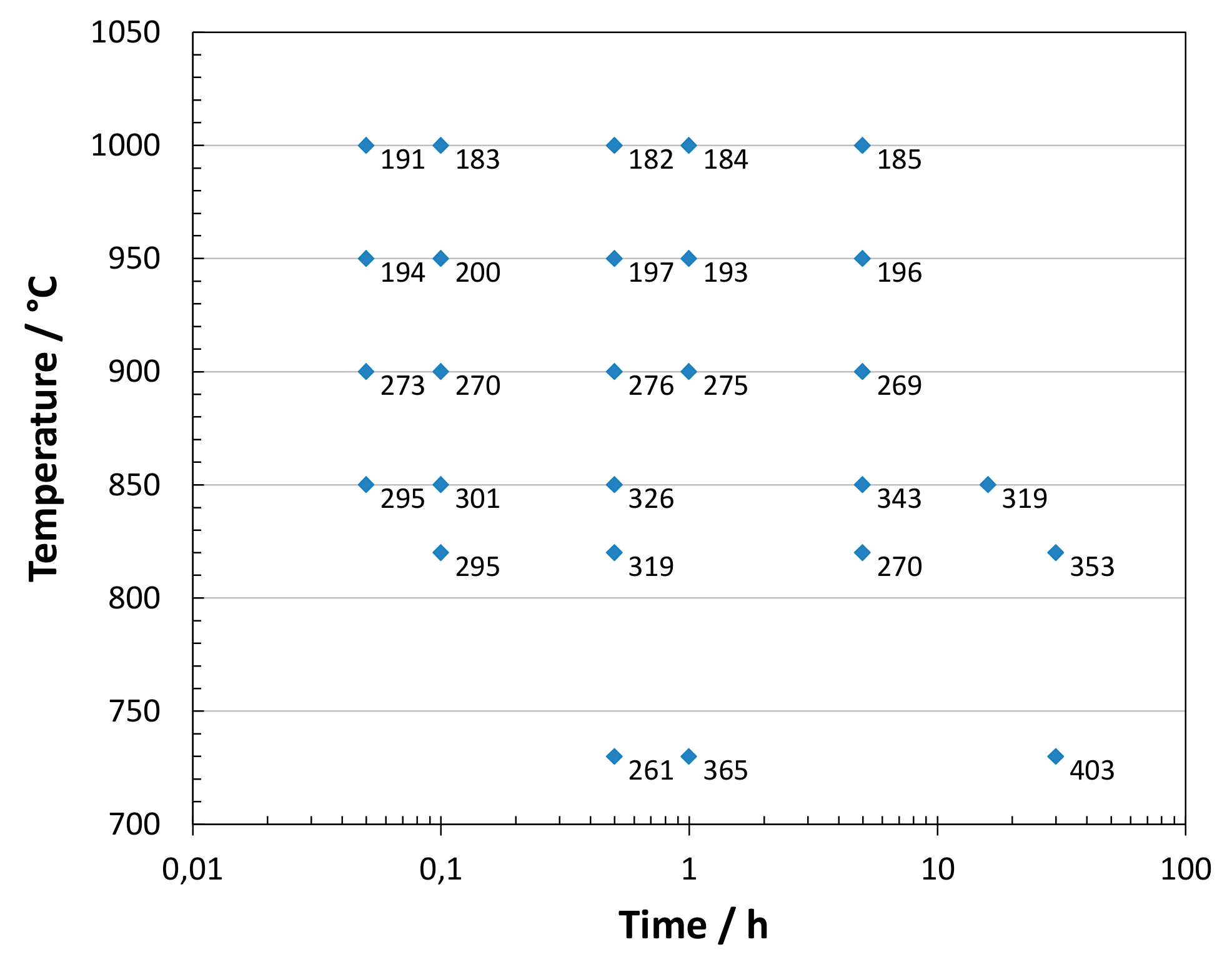
Heat-treatment experiments at 900 °C and 950 °C up to 5 h revealed an abundance of γ′ precipitates at 900 °C but hardly any precipitates at 950 °C. Additionally, the hardness was measured as a function of heat treatment temperature and time (Figure 7). For this purpose, material produced on a technical scale was used. The results showed significant hardening due to the γ′ precipitation between 725 °C and 900 °C. At 950 °C, the hardness was just slightly above the results obtained at 1000 °C. This is consistent with the microstructural information and shows that the γ′ solvus temperature is slightly above 950 °C. The result is close to the calculated solvus temperature of 968 °C obtained from Figure 3b. It is slightly higher than the solvus temperature of the γ″-phase in alloy 718 at approximately 930 °C [3]. According to the hardness results, γ′ precipitation is fastest at approximately 850 °C, which is similar to the results obtained for the γ″-phase in alloy 718 [3,4]. The data obtained at 1000 °C suggest a hardness of about 185 HV10 for the single-phase matrix. After standard heat treatment, comprising precipitation at 718 °C/8 h and 621 °C/8 h, a hardness of 455 HV10 was obtained while measurement of alloy 718 led to a hardness of 441 HV10. This is a very interesting result as it demonstrates that strength levels comparable to alloy 718 can be obtained even though the γ″ phase was replaced by the γ′ phase. This aspect will be discussed in more detail below in the context of VDM Alloy 780.
Heat treatment experiments were also conducted to determine the solvus temperature of the δ-/η-phase. Large particles, belonging to either of the two phases were still present after heat treatment at 1040 °C in a considerable amount. However, after 1050 °C hardly any larger particles were visible, so that a solvus temperature between 1040 °C and 1050 °C can be deduced. Note that a Tδ,solvus ≈ 1100 °C was predicted by Thermocalc® (Figure 3b). Thus, the existence field of the δ-phase is overestimated by the used database.
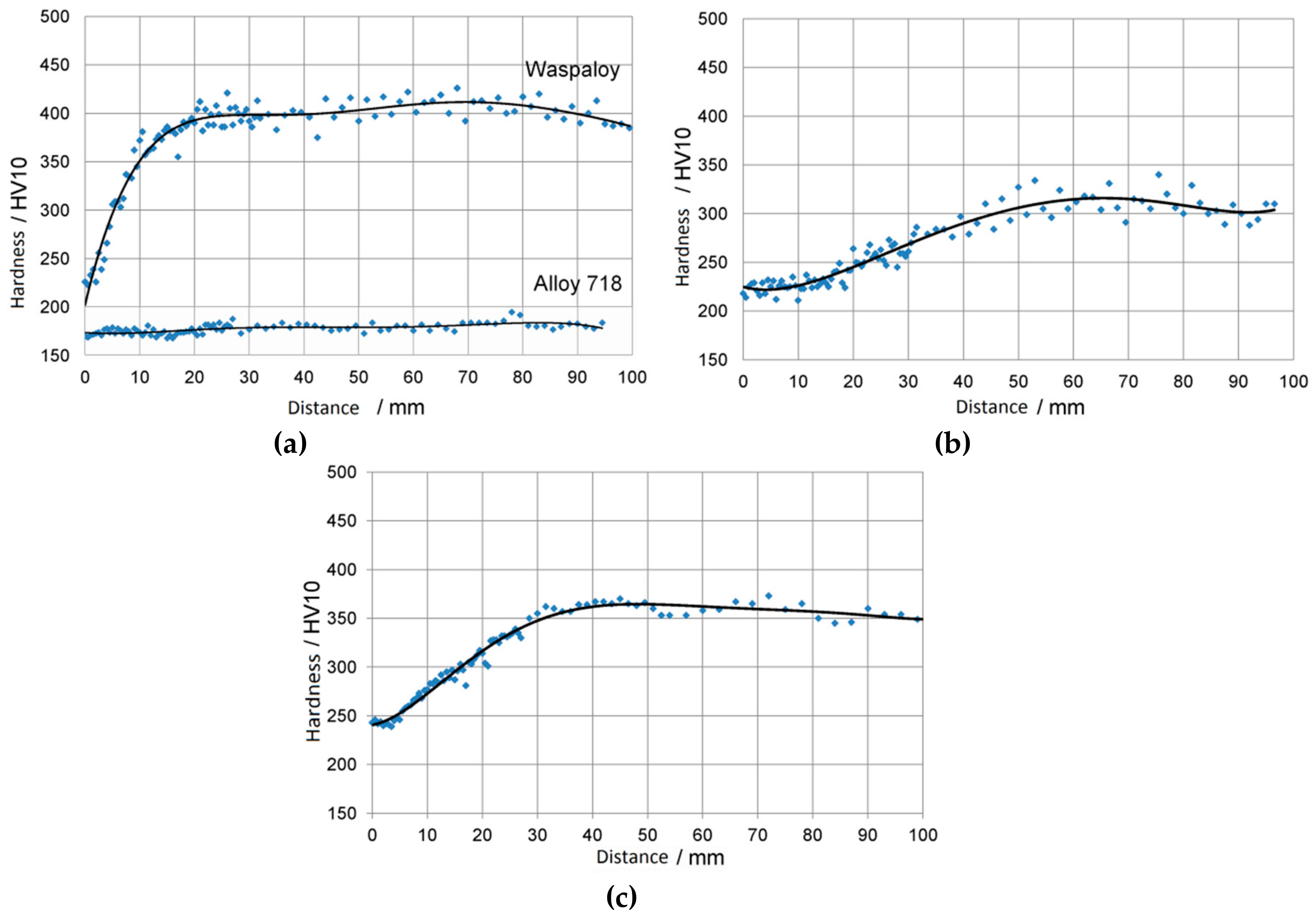
To inspect the precipitation kinetics of alloy L4 further, Jominy tests were performed. The results are displayed in Figure 1b. The hardness at the quenched end was slightly higher than the value obtained above for the single-phase state, suggesting some amount of γ′ precipitation. Nevertheless, the hardening response was sluggish, and the peak hardness obtained at a distance of about 65 mm stayed well below the hardness of the alloy in the fully heat-treated state. The precipitation kinetics was somewhat faster than in alloy 718. This can be attributed to the somewhat higher solvus temperature of the strengthening phase. However, it was significantly slower than in Waspaloy. This demonstrates that slow precipitation of the γ′-phase can be achieved provided the solvus temperature is kept low.
The results for alloy L4 showed that superalloys with the following characteristics can be designed:
  • Strength on the level of alloy 718 despite replacement of γ″ with γ′;
  • Improved microstructural stability compared to alloy 718 because of this replacement;
  • Sluggish precipitation kinetics for manufacturability due to low Tγ′, solvus;
  • Presence of the δ-phase for grain refinement during processing.
Alloy L4 appears to be an interesting candidate for 718-type applications, where an improved temperature capability of about 50 °C is required. The question is then: can the microstructural stability be improved even further while maintaining the abovementioned characteristics? Clearly, the microstructural instability of alloy L4 stems from the long plate-shaped particles forming at 750 °C. With the interpretation that they consist of Ti-rich η-phase, the direction for further alloy development becomes apparent. Firstly, the balance between the γ′-forming elements Al and Ti must be readjusted in favor of aluminum so that the amount and solvus temperature of the γ′-phase stays essentially constant while the tendency to form η-phase is reduced. Secondly, there is an upper limit for the Co content as Co also stabilizes the η-phase; it is expected to depend on the relative amounts of Al and Ti. While Co is an essential element of the alloy development strategy followed here, Ti is not.

2.2.2. The Effect of the Al/Ti Ratio

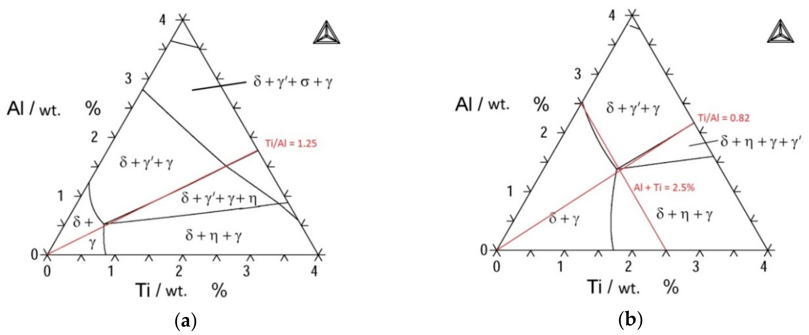
As mentioned above, the Al/Ti ratio was expected to play a major role regarding phase formation and the microstructural stability of the alloys. These effects were investigated here. To inspect the role of Ti and Al on phase formation, isothermal sections of the quasi-ternary Ni–Al–Ti system were calculated, keeping the content of all other alloying elements fixed at 18.7%Cr, 17%Co, 5.4%Nb, and 2.96%Mo. Exemplarily, sections at 800 °C and 1000 °C are shown in Figure 8. At 800 °C, the alloy should be in the γ + γ′ + δ three-phase field as γ′ is required for strengthening. In contrast, the phase fields containing the η-phase (i.e., δ + η + γ′ + γ and δ + η + γ) must be avoided to ensure good microstructural stability. Inspecting the phase boundary between δ + γ′ + γ and δ + η + γ′ + γ in Figure 8a, this boundary is essentially a line of constant Ti/Al ratio. This actually holds also true for the isothermal section at 1000 °C and all other calculated isothermal sections not shown here. At 1000 °C, the γ′-phase should be dissolved in order to ensure a sufficiently slow precipitation kinetics while the δ-phase should be present for grain refinement during processing. Of course, Tγ′,solvus should also be not too small. Otherwise, the γ′ content at service temperature would be too low for sufficient γ′ strengthening. This sets clear boundaries for the required amount of Al + Ti. At 1000 °C, the calculated phase boundary between δ + γ and δ + γ + γ′ is essentially a line of constant (Al + Ti) content with Al + Ti ≈ 2.5%. This amount sets a reasonable upper bound.
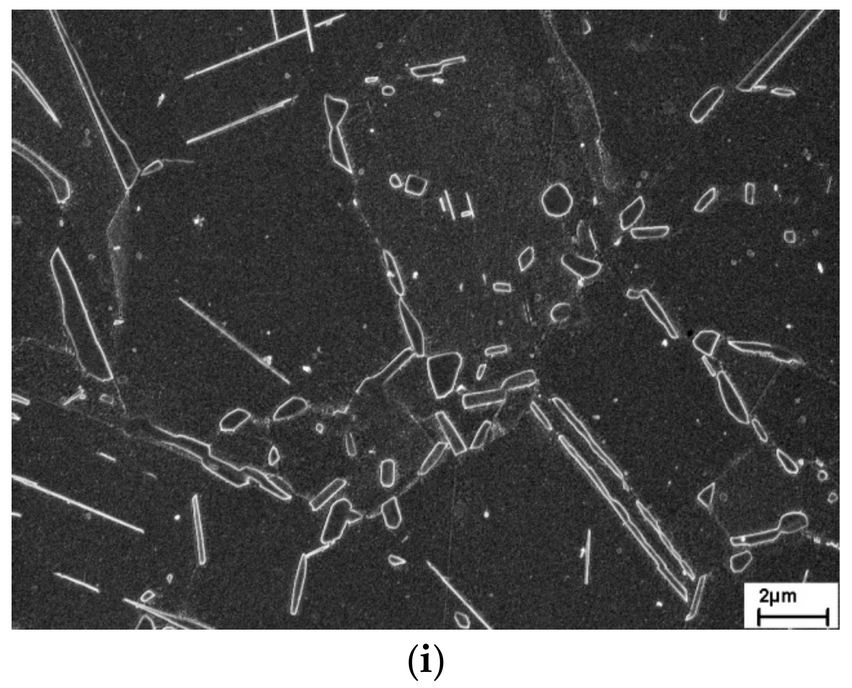
To check the predictions of the thermodynamic calculations, alloys V12 to V16 were cast. Together with alloy L4, they formed a set of alloys with varying Al and Ti content but otherwise identical composition (18.7%Cr, 17%Co, 5.4%Nb, 2.96%Mo). Their microstructural stability was investigated at 800 °C/500 h. The resulting microstructures are shown in Figure 9a–f. Note that the Ti/Al ratio decreases from Figure 9a (Ti/Al = 0.92) to Figure 9e (Ti/Al = 0.10). Apparently, the microstructures became more and more stable as the Ti/Al ratio decreased. In case of alloy L4 (1.2Al, 1.1Ti) the entire grain interior was consumed by narrow plate-shaped precipitates (Figure 9a). Sometimes, individual precipitates extended through entire grains. In the case of alloy V12 (1.2Al, 0.5Ti) the situation was similar (Figure 9b). However, the density of the plate-shaped precipitates was not quite as high. In the case of alloy V14 (1.6Al, 0.5Ti), these precipitates grew from the grain boundaries into the grain interior. Yet, they no longer consumed the whole interior. Towards alloy V13 (2.0Al, 0.5Ti) and V16 (2.0Al, 0.2Ti) the trend that these precipitates were increasingly confined to the grain boundary regions continued. The micrograph of alloy V16 at higher magnification (Figure 9f) shows a homogeneous distribution of γ′ particles in the grain interior, demonstrating the excellent microstructural stability of this alloy. The γ′ size was approximately 100 nm. One might infer that not only the Ti/Al ratio but also the sum of Al+Ti changed in this alloy series. However, if the alloys L4, V14, and V16 are compared, the sum of Al+Ti is nearly constant. Yet, there is a clear trend in the microstructural stability. Therefore, it can be concluded that the Ti/Al ratio is a key factor in controlling microstructural stability at elevated temperatures. This finding is in qualitative agreement with the thermodynamic calculations. However, there is no quantitative match. According to the calculations, the critical Ti/Al ratio, below which the η-phase does not form at 800 °C, is approximately 1.25. With the interpretation that the plate-shaped intracrystalline precipitates are η, the required Ti/Al. ratio to prevent formation of that phase is significantly smaller. It seems once again that the field of existence of the η-phase is underestimated.
Differential scanning calorimetry (DSC) measurements of alloy V16 were conducted. Using the offset of the heating curves, a γ′ solvus temperature of about 1000 °C can be deduced. This is on the upper acceptable bound. In this context, the effect of Co was explored. As mentioned in Section 2.1., Co is expected to reduce Tγ′,solvus. On the other hand, too much Co may adversely affect microstructural stability. To investigate this effect, alloy V17 was prepared. The only difference to alloy V16 is its increased Co content, namely, 25% instead of 17%. The DSC measurements revealed a reduction of Tγ′,solvus by 15 °C, demonstrating the anticipated effect of Co. The microstructure of alloy V17 after heat treatment at 800 °C/500 h is displayed in Figure 9g,h. It was very similar to that of alloy V16. There were some narrow, plate-shaped precipitates visible in the grain interior. However, careful inspection of Figure 9e shows the same for alloy V16 (see upper right corner). Figure 9h displays the grain interior at high magnification. Homogeneous distribution of the γ′ particles is apparent. Also, the aforementioned plates can be seen in this image.
Due to the fact of its promising characteristics, alloy V17 was investigated in more detail. Figure 1c shows the result of the Jominy end-quench test. Compared to alloy L4, the initial hardness at the quenched end was somewhat higher, the peak hardness was reached earlier (at a distance of about 40 mm instead of about 65 mm), and its value was higher. This is in line with the slightly higher γ′ solvus temperature of alloy V17. Still, there was a considerable difference to the results for Waspaloy, reaching a higher hardness (approximately 400 HV10 instead of about 350 HV10) considerably earlier. This once again points to the importance of Tγ′,solvus in determining the precipitation kinetics of the γ′-phase. Furthermore, the hardness of alloy V17 was measured after standard heat treatment. A value of 446 HV10 was obtained, being similar to the ones reported above for alloys L4 and 718.
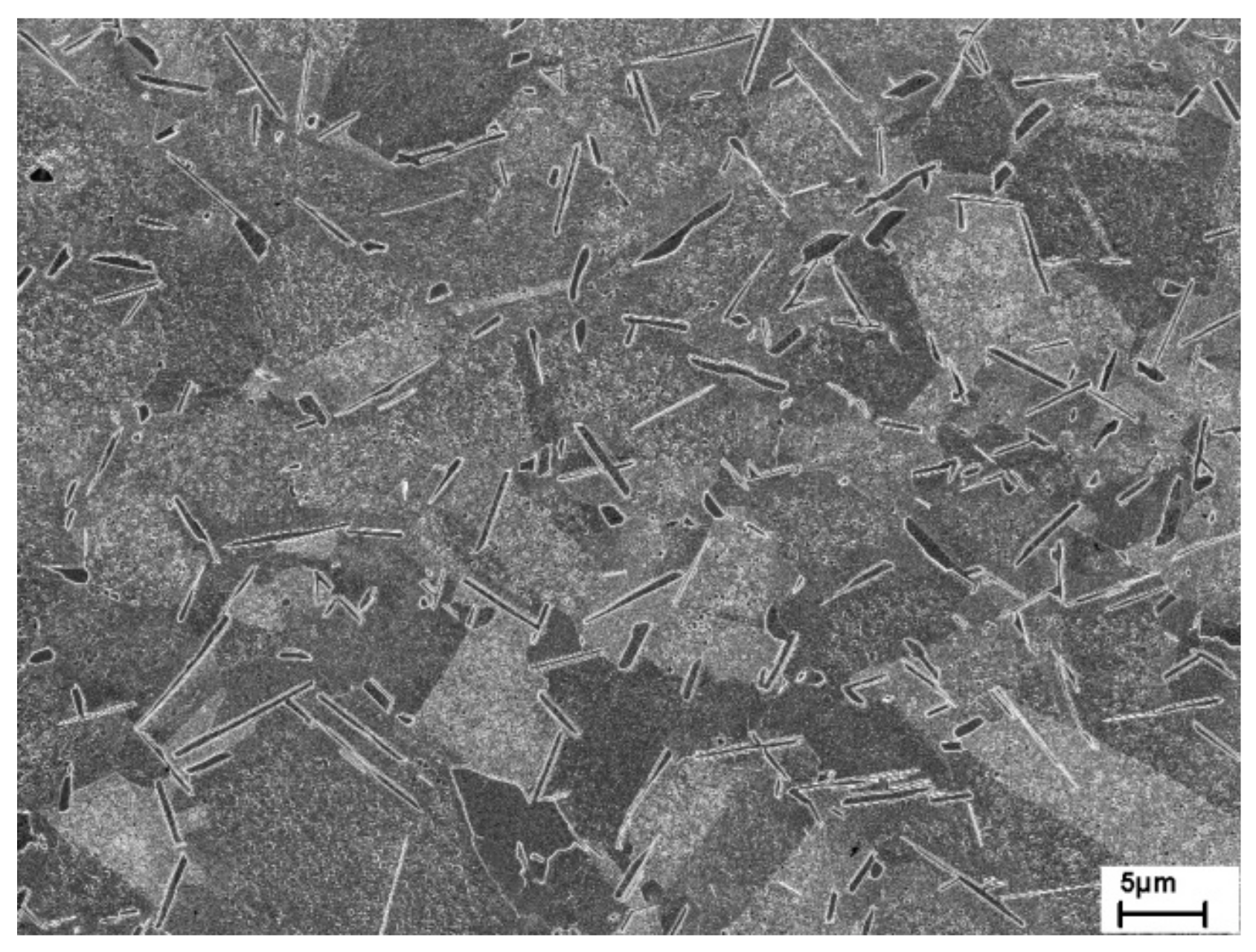
Despite the advantages of alloy V17, there is also a drawback—heat treatments at 980 °C revealed slow formation of the δ-phase. Apparently, decreasing the Ti/Al ratio relative to alloy L4 increased the stability of the microstructure at service temperature but also retarded δ-phase formation at typical forging temperatures. This is of relevance, as δ-phase is required for grain refinement during the last steps of the forging process. Thus, a series of isothermal heat treatments was conducted to investigate the kinetics of δ-phase precipitation more closely. It turned out that δ-precipitation was fastest at approximately 900 °C. Thus, a possible strategy is to heat treat the material at around 900 °C prior to forging at around 980 °C. For example, Figure 10 displays the microstructure after heat treatment at 900 °C/100 h. An abundance of large δ/η-particles, situated mainly at grain boundaries, along with γ′ precipitates can be seen. It is emphasized that the kinetics of δ/η precipitation also depends strongly on the prior deformation history. The higher the remaining dislocation density, the faster the precipitation reaction. Billet forging at a temperature of 1050 °C was conducted prior to heat treatment in the case of Figure 10.
As alloy V17 exhibited excellent microstructural stability, a high flow strength, reasonably slow precipitation kinetics of the γ′-phase, and the ability for fine grain forging due to the presence of the δ-phase, this composition essentially became VDM Alloy 780, being now introduced into the market by VDM Metals GmbH. According to reference [36], the chemical composition of VDM Alloy 780 is Ni–25Co–18Cr–3Mo–2.0Al–0.2Ti–5.4Nb. Further information on the mechanical properties and microstructural evolution of VDM Alloy 780 can be found in References [36,40]. This is not the subject of discussion in this article, which had the objective to outline the history of the alloy development with the underlying condsiderations. Nevertheless, a few findings warrant reflection in the context of this paper. Firstly, a constrained γ/γ′ misfit of 0.48% at room temperature was measured by neutron diffraction on VDM Alloy 780 [40]. This answers the question raised in Section 2.1, in that the alloy development concept followed here indeed leads to a large positive misfit, exceeding values otherwise reported for wrought γ′-strengthened superalloys. Noting, furthermore, that the sum of the precipitate-forming elements Al+Ti+Nb is considerably larger in VDM Alloy 780 than in alloy 718, namely, approximately 7.9 at.% instead of about 5.6 at.%, it becomes understandable why V17/VDM Alloy 780 attains high strength levels similar to alloy 718 at ambient temperatures despite the switch from a predominantly γ″-strengthened alloy to a γ′-strengthened alloy. Thermodynamic calculations suggest a γ′ content in VDM Alloy 780 of approximately 25%, while the first analysis of the neutron diffraction data indicates a content as high as 35% [40]. Even though more analysis is needed to determine the exact volume fraction, the available information suggests that the γ′ content not only exceeds that of alloy 718 but also that of Waspaloy. Nevertheless, Tγ′,solvus is considerably lower than that in Waspaloy. This shows that a more favorable balance between the need for a sufficiently high γ′ content at service temperature and a sufficiently low solvus temperature can be obtained than in present-day wrought superalloys. The beneficial property combination in the case of VDM Alloy 780 is mainly attributed to its high Co content.
Secondly, a remark regarding the precipitation of δ- and/or η-phase is in order. Neutron diffraction experiments conducted so far on VDM Alloy 780 can be acceptably fitted assuming either one of the two phases. This is so because the major reflections of both phases are very close, while the minor reflections are hard to detect given the relatively small amount of δ/η in the alloy. First TEM investigations on a small number of particles demonstrated the simultaneous presence of δ and η within one particle [41]. This fits to the observation made earlier in conjunction with Figure 6e and it appears likely that both phases coexist not only in VDM Alloy 780 but also in the model alloys studied here. In which form they coexist and whether our distinction between δ- and η-phase based on the morphology of the precipitates holds true remains to be seen.
Finally, it is mentioned that solvus temperatures of the precipitate phases were determined by in situ neutron diffraction [40]. The results suggest solvus temperatures of γ′ and δ/η of about 995 °C–1000 °C and 1020 °C–1030 °C, respectively. The result on Tγ′,solvus fits well with the thermodynamic calculations and the DSC results obtained on alloy V17, even though a slightly lower solvus temperature was obtained in both cases. However, the results on the solvus temperature of the δ/η-phase are not in line with the calculated results of Tδ,solvus ≈ 1150 °C. It shows again that the existence fields of δ/η are not represented well in the used database. Compared to alloy L4, the microstructural stability is much improved. However, the gap between Tγ′,solvus and Tδ/η,solvus also diminished somewhat, requiring a more careful control of the forging process parameters.

3. Summary

A new design concept for superalloys with 718-type properties, yet significantly improved temperature capability was discussed. It was demonstrated that γ″ strengthening can be replaced by γ′ strengthening without losing the key advantages of alloy 718, namely, its slow precipitation kinetics—leading to excellent manufacturability—and high strength at ambient temperatures. The obtained benefit is a stable microstructure at elevated temperature, allowing for higher application temperatures. Addition of Co, replacing Fe and Ni, is the single most important measure of the design concept. This limits the solvus temperature of the γ′-phase and, thus, slows down the precipitation kinetics. Furthermore, it increases the γ′ content at service temperature. This leads, in combination with the large positive γ/γ′ misfit obtained in these alloys, to a flow strength similar to alloy 718. Compared to Waspaloy as a classical γ′-strengthened wrought superalloy, the overall result is a lower γ′ solvus temperature, a slower γ′ precipitation kinetics, a higher γ′ content, and a higher strength. Furthermore, as Co also stabilizes the δ- and η-phases, fine grain forging by means of these phases is still possible in contrast to conventional γ′-strengthened superalloys. Cobalt is important in this context because the elevated Al content required for the switch from γ″ to γ′ hardening would otherwise prevent formation of these phases.
The results obtained here not only show a general route for the development of 718-type superalloys with improved temperature capability. They have already been implemented for the design of VDM Alloy 780, being now introduced in the market. It contains 25% Co replacing Fe and Ni, 2% Al, 0.2% Ti while maintaining Cr, Mo, and Nb such as in alloy 718. A low Ti/Al ratio was deliberately chosen to ensure microstructural stability at elevated temperatures.

Author Contributions

Conceptualization, J.R. and T.H.; Methodology: J.R and T.H.; Investigation: T.H.; Validation: T.H.; Writing—Original Draft, Review & Editing: J.R.; Resources: J.R. and B.G.; Supervision: J.R. and B.G.; Funding Acquisition: J.R. and B.G.

Funding

This research was funded by VDM Metals GmbH.

Acknowledgments

Triple melting of alloy L4 on a technical scale at Institut für Metallurgische Prozesstechnik und Metallrecycling, RWTH Aachen, and forging of this alloy at Institut für Bildsame Formgebung, RWTH Aachen is gratefully acknowledged. We also acknowledge support by the German Research Foundation and the Open Access Publication Funds of the Technische Universität Braunschweig.

Conflicts of Interest

The authors declare no conflict of interest.

References

  1. Eiselstein, H.L. Age-hardenable nickel alloy. U.S. Patent US3046108A, 24 July 1962. [Google Scholar]
  2. Eiselstein, H.L.; Tillack, D.J. The Invention and Definition of Alloy 625. In Superalloys 718, 625 and Various Derivatives; Loria, E.A., Ed.; TMS: Warrendale, PA, USA, 1991; pp. 1–14. [Google Scholar]
  3. Brooks, J.W.; Bridges, P.J. Metallurgical Stability of Inconel Alloy 718. In Superalloys 1988; Reichmann, S., Duhl, D.N., Maurer, G., Antolovich, S., Lund, C., Eds.; TMS: Warrendale, PA, USA, 1988; pp. 33–42. [Google Scholar]
  4. Oradei-Basile, A.; Radavich, J.F.A.; Radavich, J.F. A Current T-T-T Diagram for Wrought Alloy 718. In Superalloys 718, 625 and Various Derivatives; Loria, E.A., Ed.; TMS: Warrendale, PA, USA, 1991; pp. 325–335. [Google Scholar]
  5. Cozar, R.; Pineau, A. Morphology of y’ and y” precipitates and thermal stability of inconel 718 type alloys. Metall. Trans. 1973, 4, 47–59. [Google Scholar] [CrossRef]
  6. Jackson, M.P.; Reed, R.C. Heat treatment of UDIMET 720Li: the effect of microstructure on properties. Mat. Sci. Eng. 1999, A259, 85–97. [Google Scholar] [CrossRef]
  7. Cao, W.-D.; Kennedy, R. Role of Chemistry in 718-Type Alloys – Allvac® 718PlusTM Alloy Development. In Superalloys 2004; Green, K.A., Pollock, T.M., Harada, H., Howson, T.E., Reed, R.C., Schirra, J.J., Walston, S., Eds.; TMS: Warrendale, PA, USA, 2004; pp. 91–99. [Google Scholar]
  8. Collier, J.P.; Wong, S.H.; Phillips, J.C.; Tien, J.K. The effect of varying AI, Ti, and Nb content on the phase stability of INCONEL 718. Metall. Trans. 1988, 19A, 1657–1666. [Google Scholar] [CrossRef]
  9. Manriquez, J.A.; Bretz, P.L.; Rabenberg, L.; Tien, J.K. The High Temperature Stability of IN718 Derivative Alloys. In Superalloys 1992; Antolovich, S.D., Stusrud, R.W., MacKay, R.A., Anton, D.L., Khan, T., Kissinger, R.D., Klarstrom, D.L., Eds.; TMS: Warrendale, PA, USA, 1992; pp. 507–516. [Google Scholar]
  10. Xie, X.S.; Dong, J.X.; Zhang, M.C. Research and Development of Inconel 718 Type Superalloy. Mater. Sci. Forum 2007, 539–543, 262–269. [Google Scholar] [CrossRef]
  11. Mignanelli, P.M.; Jones, N.G.; Pickering, E.J.; Messe, O.M.D.M.; Rae, C.M.F.; Hardy, M.C.; Stone, H.J. Gamma-gamma prime-gamma double prime dual-superlattice superalloys. Scr. Mater. 2017, 136, 136–140. [Google Scholar] [CrossRef]
  12. McDevitt, E. Effect of Temperature and Strain During Forging on Subsequent Delta Phase Precipitation During Solution Annealing in ATI 718Plus® Alloy. In 7th International Symposium on Superalloy 718 and Derivatives; Ott, E.A., Groh, J.R., Banik, A., Dempster, I., Gabb, T.P., Helmink, R., Liu, X., Mitchell, A., Sjöberg, G.P., Wusatowska-Sarnek, A., Eds.; TMS: Warrendale, PA, USA, 2010; pp. 307–319. [Google Scholar]
  13. Pickering, E.J.; Mathur, H.; Bhowmik, A.; Messe, O.M.D.M.; Barnard, J.S.; Hardy, M.C.; Krakow, R.; Loehnert, K.; Stone, H.J.; Rae, C.M.F. Grain-boundary precipitation in Allvac 718Plus. Acta Mater. 2012, 60, 2757–2769. [Google Scholar] [CrossRef]
  14. Messe, O.M.; Barnard, J.S.; Pickering, E.J.; Midgley, P.A.; Rae, C.M.F. On the precipitation of delta phase in ALLVAC® 718Plus. Phil. Mag. 2014, 94, 1132–1152. [Google Scholar] [CrossRef]
  15. Devaux, A.; Helstroffer, A.; Cormier, J.; Villechaise, P.; Douin, J.; Hantcherli, M.; Pettinari-Sturmel, F. Effect of Aging Heat-Treatment on Mechanical Properties of AD730TM Superalloy. In 8th International Symposium on Superalloy 718 and Derivatives; Ott, E.A., Banik, A., Andersson, J., Dempster, I., Gabb, T.P., Groh, J., Heck, K., Helmink, R., Liu, X., Wusatowska-Sarnek, A., Eds.; TMS: Warrendale, PA, USA, 2014; pp. 521–535. [Google Scholar]
  16. Heaney, J.A.; Lasonde, M.L.; Powell, A.M.; Bond, B.J.; O’Brien, C.M. Development of a New Cast and Wrought Alloy (René 65) for High Temperature Disk Applications. In 8th International Symposium on Superalloy 718 and Derivatives; Ott, E.A., Banik, A., Andersson, J., Dempster, I., Gabb, T.P., Groh, J., Heck, K., Helmink, R., Liu, X., Wusatowska-Sarnek, A., Eds.; TMS: Warrendale, PA, USA, 2014; pp. 67–77. [Google Scholar]
  17. Fedorova, T.; Rösler, J.; Gehrmann, B.; Klöwer, J. Invention of a New 718-Type Ni-Co Superalloy Family for High Temperature Applications at 750 °C. In 8th International Symposium on Superalloy 718 and Derivatives; Ott, E.A., Banik, A., Andersson, J., Dempster, I., Gabb, T.P., Groh, J., Heck, K., Helmink, R., Liu, X., Wusatowska-Sarnek, A., Eds.; TMS: Warrendale, PA, USA, 2014; pp. 587–599. [Google Scholar]
  18. Fedorova, T.; Rösler, J.; Klöwer, J.; Gehrmann, B. Development of a new 718-type Ni-Co superalloy family for high temperature applications at 750 °C. MATEC Web Conf. 2014, 14, 01003. [Google Scholar] [CrossRef]
  19. Fedorova, T. Entwicklung einer neuen Nickelbasis-Legierung auf Basis von Alloy 718; Cuvillier Verlag: Göttingen, Germany, 2013. [Google Scholar]
  20. Frost, H.J.; Ashby, M.F. Deformation Mechanism Maps; Pergamon Press: Oxford, UK, 1982. [Google Scholar]
  21. Karunaratne, M.S.A.; Carter, P.; Reed, R.C. On the diffusion of aluminium and titanium in the Ni-rich Ni–Al–Ti system between 900 and 1200 °C. Acta Mater. 2001, 49, 861–875. [Google Scholar] [CrossRef]
  22. Karunaratne, M.S.A.; Reed, R.C. Interdiffusion of Niobium and Molybdenum in Nickel between 900–1300 °C. Defect Diffus. Forum 2005, 237, 420–425. [Google Scholar] [CrossRef]
  23. Karunaratne, M.S.A.; Cox, D.C.; Carter, P.; Reed, R.C. Modelling of the Microsegregation in CMSX-4 Superalloy and its Homogenisation During Heat Treatment. In Superalloys 2000; Pollock, T.M., Kissinger, R.D., Bowman, R.R., Green, K.A., McLean, M., Olson, S., Schirra, J.J., Eds.; TMS: Warrendale, PA, USA, 2000; pp. 263–272. [Google Scholar]
  24. Devaux, A.; Nazé, L.; Molins, R.; Pineau, A.; Organista, A.; Gudeou, J.Y.; Uginet, J.F.; Héritier, P. Gamma double prime precipitation kinetic in Alloy 718. Mat. Sci. Eng. A 2008, 486, 117–122. [Google Scholar] [CrossRef]
  25. Li, X.; Saunders, N.; Miodownik, A.P. The coarsening kinetics of γ′ particles in nickel-based alloys. Metall. Mater. Trans. 2002, 33A, 3367–3373. [Google Scholar] [CrossRef]
  26. Koul, A.K.; Thamburaj, R. Serrated grain boundary formation potential of Ni-based superalloys and its implications. Metall. Trans. 1985, 16A, 17–26. [Google Scholar] [CrossRef]
  27. Kinzel, S.; Gabel, J.; Völkl, R.; Glatzel, U. Reasons for Volume Contraction after Long-Term Annealing of Waspaloy. Adv. Eng. Mater. 2015, 17, 1106–1112. [Google Scholar] [CrossRef]
  28. Stone, H.J.; Holden, T.M.; Reed, R.C. On the generation of microstrains during the plastic deformation of Waspaloy. Acta Mater. 1999, 47, 4435–4448. [Google Scholar] [CrossRef]
  29. Chang, K.-M.; Henry, M.F.; Benz, M.G. Metallurgical control of fatigue crack propagation in superalloys. JOM 1990, 42, 29–35. [Google Scholar] [CrossRef]
  30. Slama, C.; Servant, C.; Cizeron, G. Aging of the Inconel 718 alloy between 500 and 750 C. J. Mater. Res. 1997, 12, 2298–2316. [Google Scholar] [CrossRef]
  31. Tien, J.K.; Copley, S.M. The effect of orientation and sense of applied uniaxial stress on the morphology of coherent gamma prime precipitates in stress annealed nickel-base superalloy crystals. Metall. Trans. 1971, 2, 543–553. [Google Scholar] [CrossRef]
  32. Ricks, R.A.; Porter, A.J.; Ecob, R.C. The growth of γ′ precipitates in nickel-base superalloys. Acta Metall. 1983, 31, 43–53. [Google Scholar] [CrossRef]
  33. Mishima, Y.; Ochiai, S.; Suzuki, T. Lattice parameters of Ni (γ), Ni3Al (γ′) and Ni3Ga (γ′) solid solutions with additions of transition and B-subgroup elements. Acta Metall. 1985, 33, 1161–1169. [Google Scholar] [CrossRef]
  34. Jena, A.K.; Chaturvedi, M.C. The role of alloying elements in the design of nickel-base superalloys. J. Mater. Sci. 1984, 19, 3121–3139. [Google Scholar] [CrossRef]
  35. Bäker, M.; Rösler, J.; Hentrich, T.; Ackland, G. Influence of transition group elements on the stability of the δ- and η-phase in nickelbase alloys. Modelling Simul. Mater. Sci. Eng. 2018, 26, 015005. [Google Scholar] [CrossRef]
  36. Bergner, M.; Rösler, J.; Gehrmann, B.; Klöwer, J. Effect of Heat Treatment on Microstructure and Mechanical Properties of VDM Alloy 780 Premium. In Superalloy 718 and Derivatives; Ott, E.A., Liu, X., Andersson, J., Bi, Z., Bockenstedt, K., Dempster, I., Groh, J., Heck, K., Jablonski, P., Kaplan, M., et al., Eds.; TMS: Warrendale, PA, USA, 2018; pp. 489–499. [Google Scholar]
  37. Mukherji, D.; Strunz, P.; Del Genovese, D.; Gilles, R.; Rösler, J.; Wiedenmann, A. Investigation of microstructural changes in INCONEL 706 at high temperatures by In-Situ small-angle neutron scattering. Met. Mater. Trans. 2003, 34A, 2781–2792. [Google Scholar] [CrossRef]
  38. Detrois, M.; Antonov, S.; Helmink, R.C.; Tin, S. Precipitate Phase Stability in γ-γ′-δ-η Ni-Base Superalloys. JOM 2014, 66, 2478–2485. [Google Scholar] [CrossRef]
  39. Tomihisa, K.; Kaneno, Y.; Takasugi, T. Phase relation and microstructure in Ni3Al–Ni3Ti–Ni3Nb pseudo-ternary alloy system. Intermetallics 2002, 10, 247–254. [Google Scholar] [CrossRef]
  40. Solis, C.; Munke, J.; Bergner, M.; Kriele, A.; Mühlbauer, M.J.; Cheptiakov, D.V.; Gehrmann, B.; Rösler, J.; Gilles, R. In Situ Characterization at Elevated Temperatures of a New Ni-Based Superalloy VDM-780 Premium. Metall. Trans. 2018, 49A, 4373–4381. [Google Scholar] [CrossRef]
  41. Ghica, C.; Solis, C.; Munke, J.; Stark, A.; Gehrmann, B.; Bergner, M.; Rösler, J.; Gilles, R. HRTEM analysis of the high-temperature phases of the newly developed high-temperature Ni-base superalloy VDM 780 Premium. J. Alloys Compd. 2019, 814, 152157. [Google Scholar] [CrossRef]
Figure 1. Results of the Jominy end-quench tests conducted for alloy 718 and Waspaloy (a), alloy L4 (b), and alloy V17 (c). Shown is the HV10 Vickers hardness as a function of the distance from the quenched end (after reference [19] with permission from Cuvillier Verlag).
Metals 09 01130 g001
Figure 2. The microstructure of alloys L14 (a,b), L15 (c,d), L4 (e), L17 (f,g), and L18 (h,i) according to Table 1. Note that the Co content increases from (a) to (i) (ad, fh: in-lens detector, e: SE detector; Figure 2e from reference [19] with permission from Cuvillier Verlag).
Metals 09 01130 g002aMetals 09 01130 g002b
Figure 3. A quasi-binary Ni-Co phase diagram at Al = 1.2%, Ti = 1.1%, Cr = 18.7%, Mo = 2.96%, Nb = 5.4%, and C = 0.025% calculated with Thermocalc® (a). Except for the solidus line, all lines mark the onset of the formation of the respective phases. In (b), the calculated phase fractions are given as a function of temperature for a Co content of 17% (database: TTNi7) (Figure 3b after reference [19] with permission from Cuvillier Verlag).
Metals 09 01130 g003
Figure 4. The microstructures of alloys L3 and L6 according to Table 1. The chemical composition of both alloys is identical except for a Co content of 17% (a) and 30% (b). Note that the relatively large particles with a size of a few micrometers and protruding relatively far out of the surface are Nb-rich carbides (SE detector).
Metals 09 01130 g004
Figure 5. The microstructure of alloy L4 after billet forging on a technical scale and subsequent standard heat treatment (in-lens detector; from reference [19] with permission from Cuvillier Verlag).
Metals 09 01130 g005
Figure 6. The microstructure of alloy 718 after heat treatment at 700 °C/500 h (a,b) and alloy L4 after the same heat treatment (c,d) and after 750 °C/500 h (e) (SE detector; Figure 6c,e from reference [19] with permission from Cuvillier Verlag).
Metals 09 01130 g006
Figure 7. The HV10 Vickers hardness of alloy L4 as a function of isothermal heat-treatment temperature and time.
Metals 09 01130 g007
Figure 8. Calculated isothermal sections of the quasi-ternary Ni–Al–Ti system at 800 °C (a) and 1000 °C (b). The composition of the other alloying elements was set to 17% Co, 5.4% Nb, 18.7% Cr, and 2.96% Mo. Lines of constant Ti/Al ratio and (Al+Ti) content are also shown (database: TTNi7) (Figure 8b after reference [19] with permission from Cuvillier Verlag).
Metals 09 01130 g008
Figure 9. The microstructure of alloy L4 (a), V12 (b), V14 (c), V13 (d), V16 (e,f), and V17 (g,h) after heat treatment at 800 °C/500 h. The Ti/Al ratio decreases from (a) to (f). Note the 2× magnification in (e) compared to (ad). Alloy V17 differs from V16 in its higher Co content (25% instead of 17%). (ae,g) in-lens detector; (f,h): SE detector.
Metals 09 01130 g009aMetals 09 01130 g009b
Figure 10. The microstructure of alloy V17 after billet forging at 1050 °C and heat treatment at 900 °C/100 h (in-lens detector).
Metals 09 01130 g010
Table 1. Nominal chemical compositions of selected 718-type superalloys in wt.%. The corresponding compositions in at.% are given in brackets. Systematic variations of concentrations within an alloy series are highlighted.
NameNiCrCoFeMoWAlTiNbRef.
Alloy 718Bal.18.1
(20.3)
-18.0
(18.8)
2.90
(1.76)
-0.45
(0.97)
1.00
(1.22)
5.40
(3.38)
[7]
ATI 718Plus®Bal.18.0
(20.1)
9.0
(8.89)
10.0
(10.4)
2.80
(1.70)
1.0
(0.32)
1.45
(3.13)
0.70
(0.85)
5.45
(3.41)
[7]
VDM Alloy 780Bal.18.0
(20.0)
25.0
(24.5)
-3.0
(1.81)
-2.0
(4.29)
0.2
(0.24)
5.4
(3.36)
[36]
L14Bal.18.7
(20.3)
10.0
(9.59)
-2.96
(1.74)
-1.20
(2.51)
1.10
(1.30)
5.40
(3.28)
L15Bal.18.7
(20.3)
14.0
(13.4)
-2.96
(1.74)
-1.20
(2.51)
1.10
(1.30)
5.40
(3.29)
L4Bal.18.7
(20.3)
17.0
(16.3)
-2.96
(1.74)
-1.20
(2.51)
1.10
(1.30)
5.40
(3.29)
L17Bal.18.7
(20.3)
25.0
(24.0)
-2.96
(1.74)
-1.20
(2.52)
1.10
(1.30)
5.40
(3.29)
L18Bal.18.7
(20.3)
30.0
(28.8)
-2.96
(1.74)
-1.20
(2.52)
1.10
(1.30)
5.40
(3.29)
L3Bal.18.7
(20.5)
17.0
(16.4)
-2.96
(1.76)
-0.65
(1.37)
0.75
(0.89)
5.40
(3.31)
L6Bal.18.7
(20.5)
30.0
(29.0)
-2.96
(1.76)
-0.65
(1.37)
0.75
(0.89)
5.40
(3.31)
V12Bal.18.7
(20.4)
17.0
(16.3)
-2.96
(1.75)
-1.20
(2.52)
0.50
(0.59)
5.40
(3.29)
V14Bal.18.7
(20.3)
17.0
(16.3)
-2.96
(1.74)
-1.60
(3.34)
0.50
(0.59)
5.40
(3.28)
V13Bal.18.7
(20.2)
17.0
(16.2)
-2.96
(1.73)
-2.00
(4.16)
0.50
(0.59)
5.40
(3.26)
V16Bal.18.7
(20.2)
17.0
(16.2)
-2.96
(1.73)
-2.00
(4.16)
0.20
(0.23)
5.40
(3.26)
V17Bal.18.7
(20.2)
25.0
(23.8)
-2.96
(1.73)
-2.00
(4.16)
0.20
(0.23)
5.40
(3.26)

