Author Contributions
Conceptualization, Y.-S.P. and A.A.; methodology, S.D.; formal analysis, A.A. and S.D.; investigation, S.D.; data curation, project administration, J.-H.P.; A.A.; writing—original draft preparation, S.D. and Y.-S.P.; writing—review and editing, A.A.; supervision, J.-H.P., A.A. and Y.-S.P.; funding acquisition, A.A. and Y.-S.P.
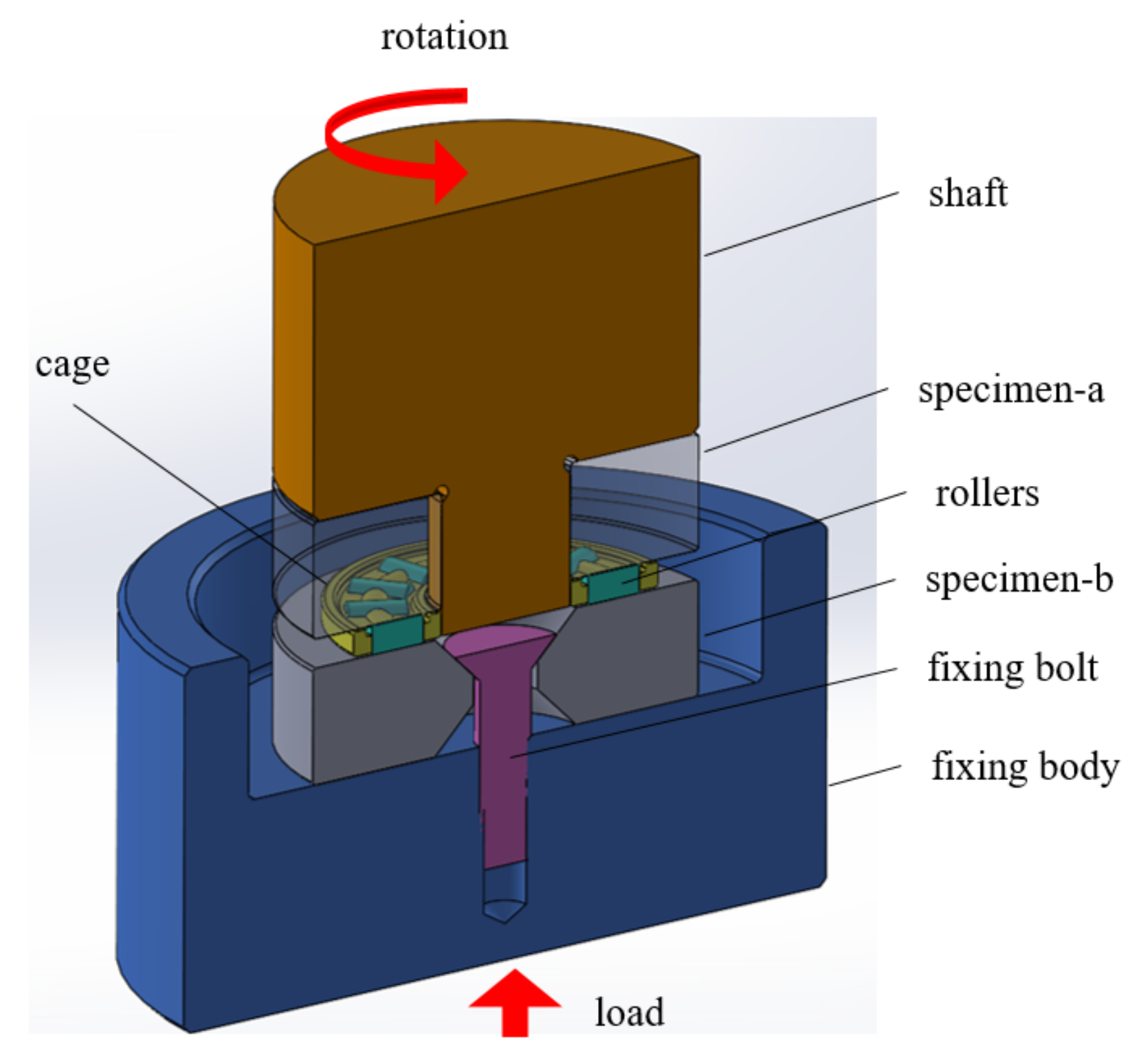
Figure 1.
Needle roller bearing fatigue test configuration.
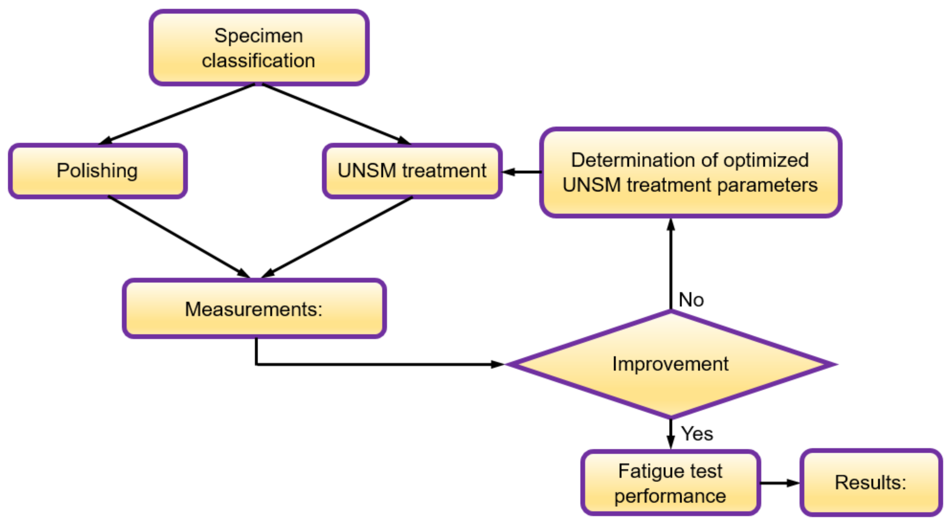
Figure 2.
A flowchart describing the research stages.
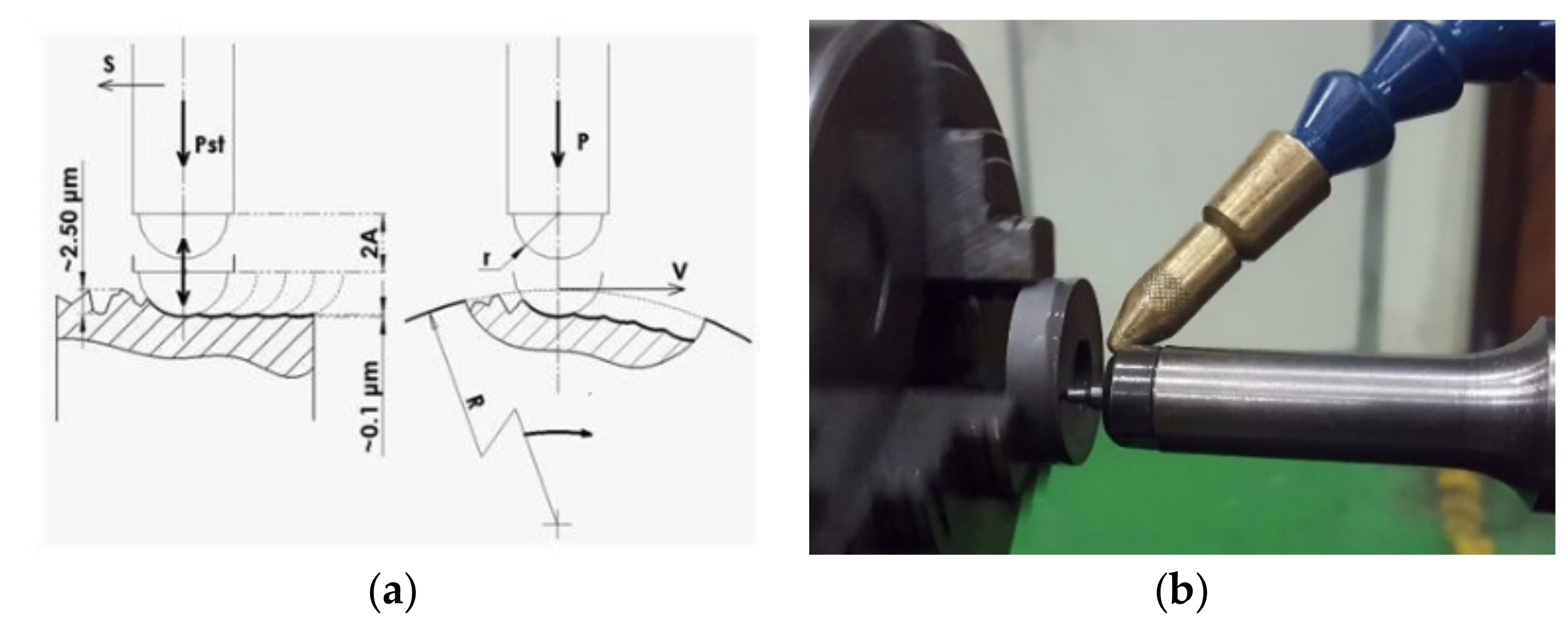
Figure 3.
(a) Ultrasonic nanocrystal surface modification (UNSM) treatment principles and (b) the processing of the specimen.
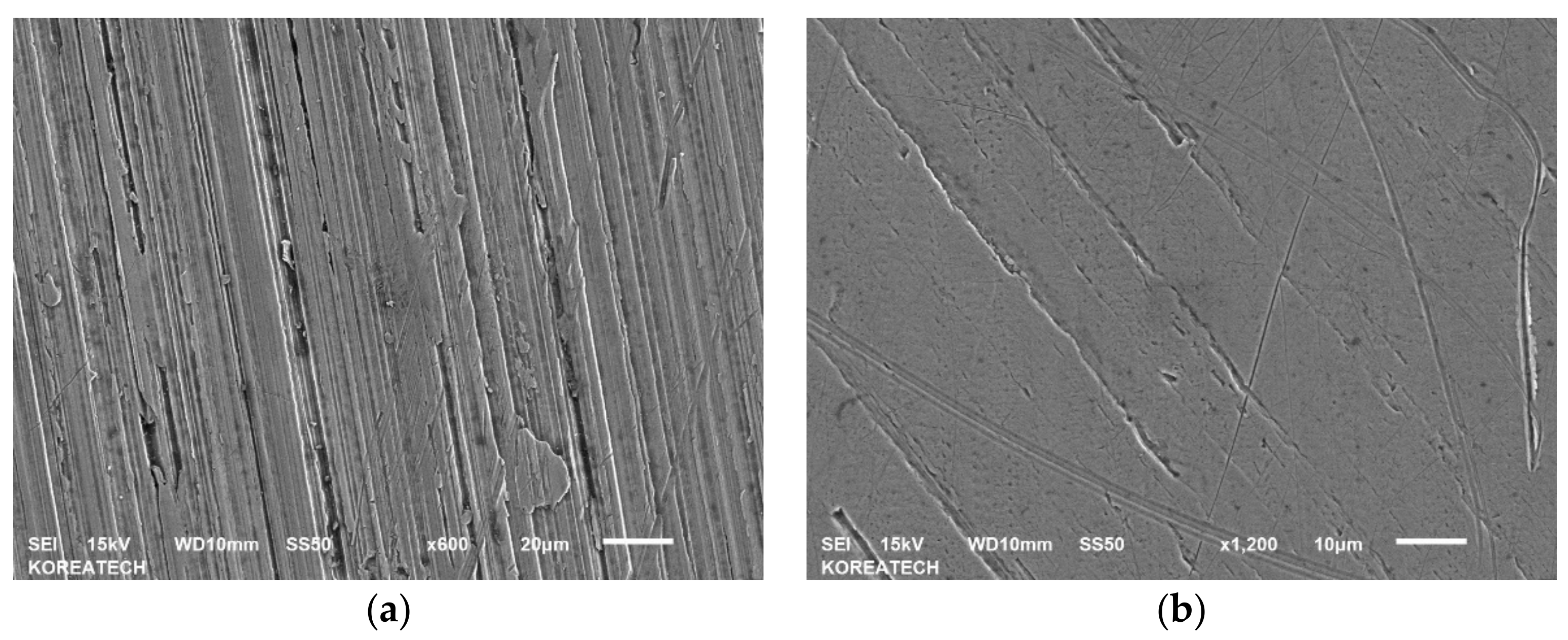
Figure 4.
SEM images of the untreated (a) and UNSM-treated (b) specimens.
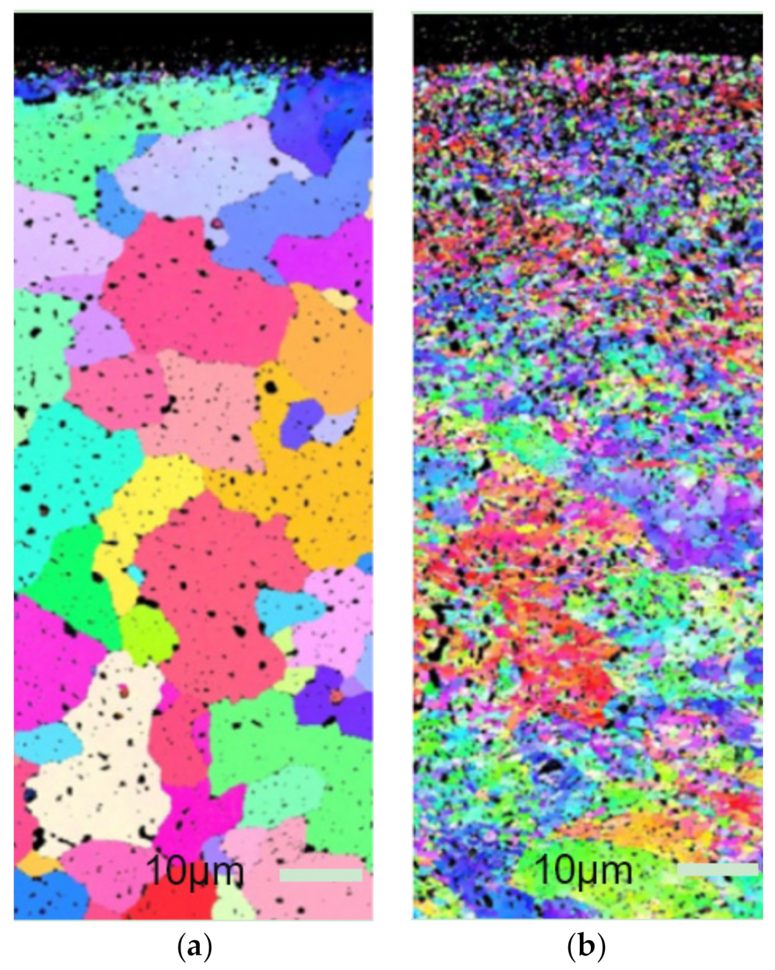
Figure 5.
Cross-sectional EBSD images of the untreated (a) and UNSM-treated (b) specimens.
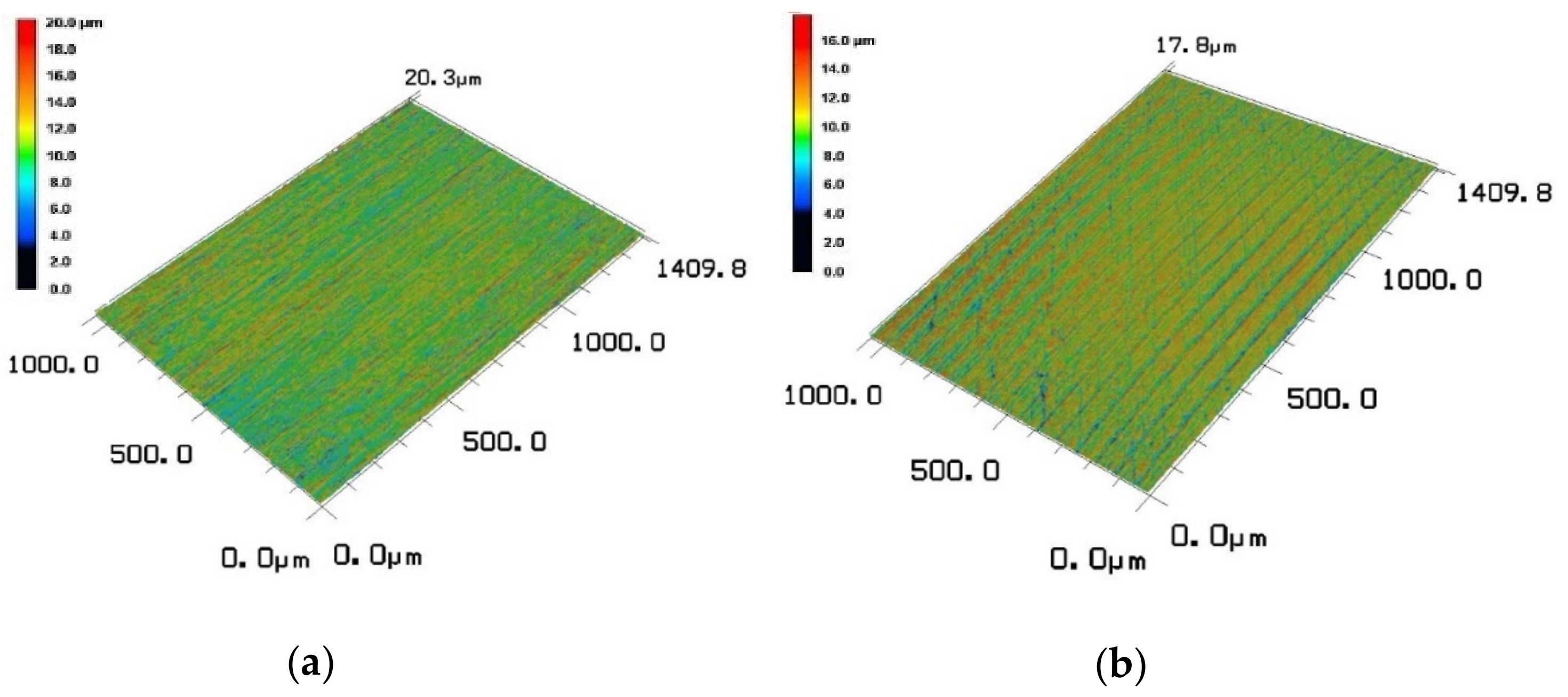
Figure 6.
3D LSM images of the untreated (a) and UNSM-treated (b) specimens.
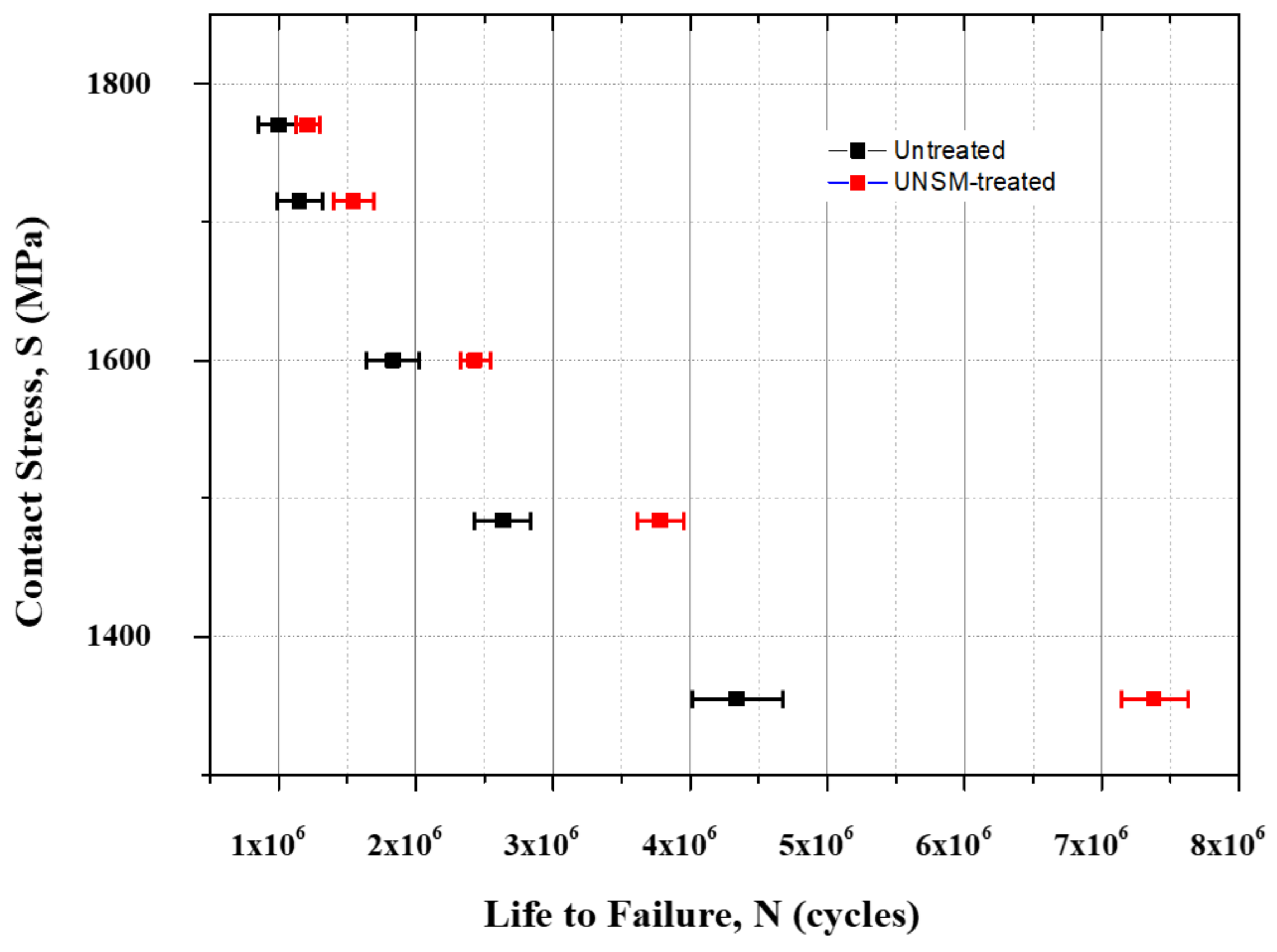
Figure 7.
Comparison of the S–N curve of the untreated and UNSM-treated specimens.
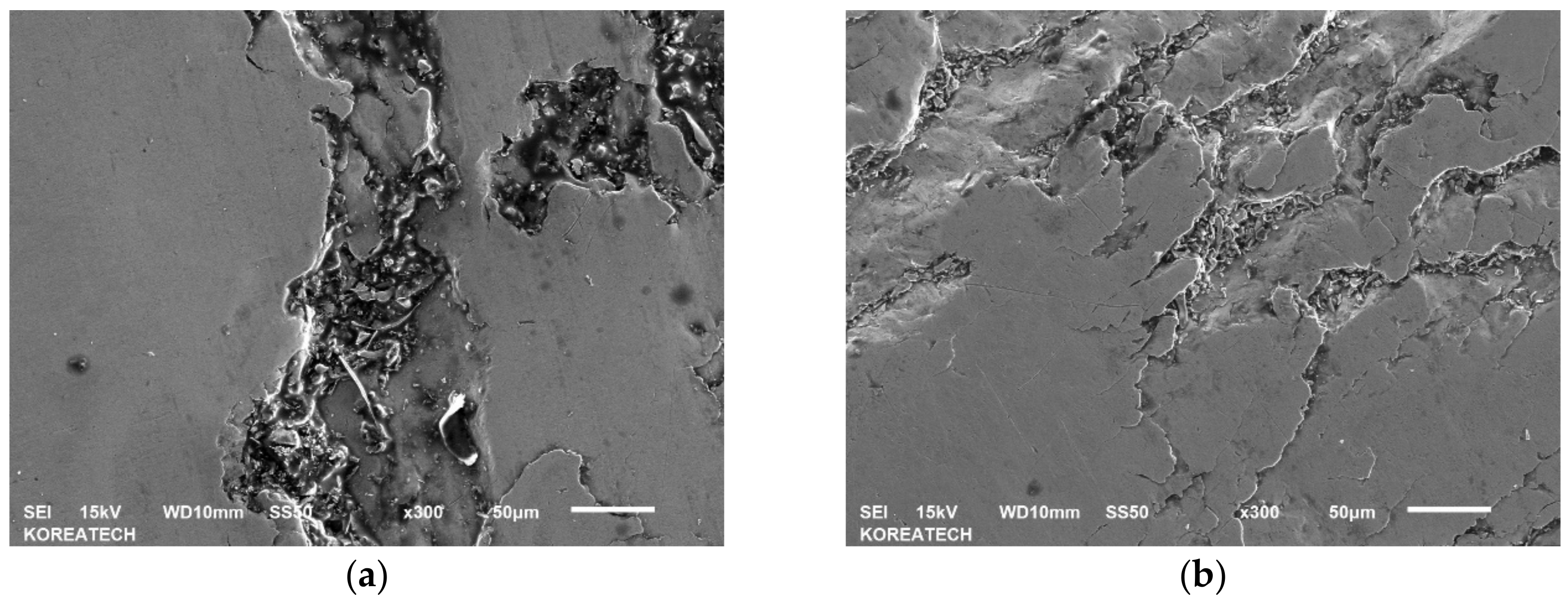
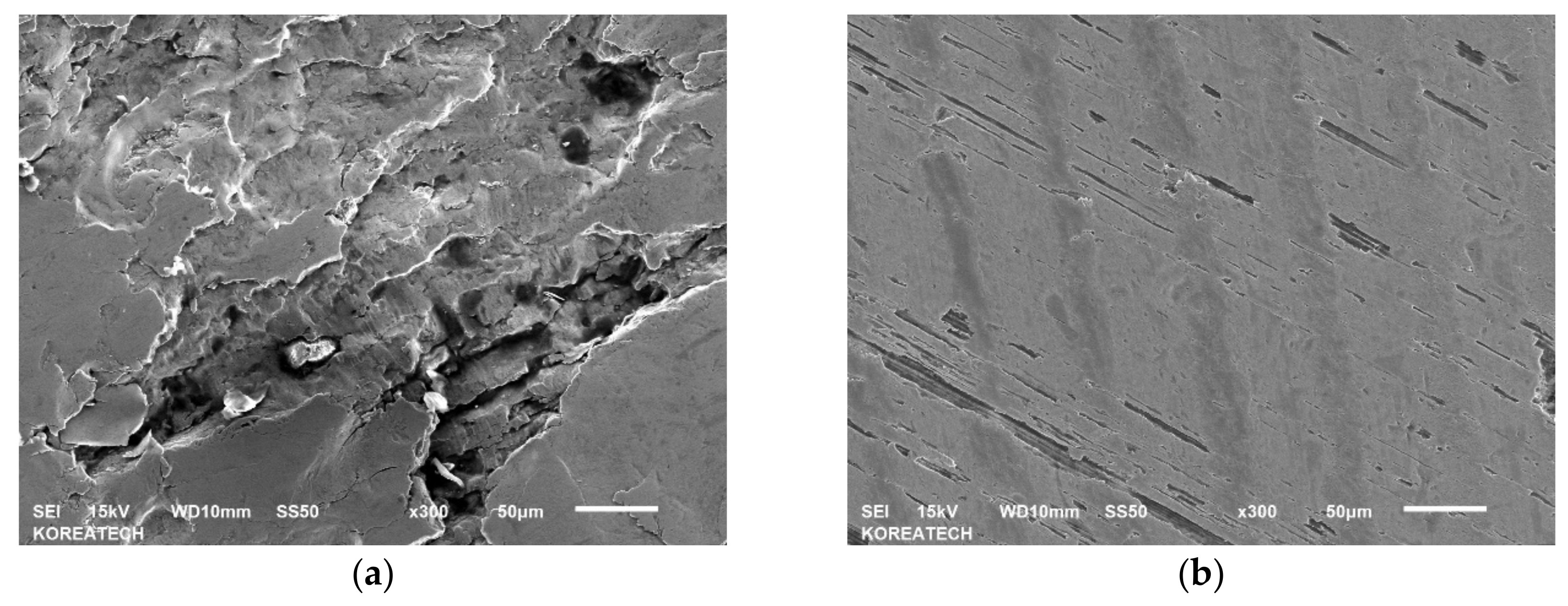
Figure 8.
SEM images of the untreated #5NRB (1.150 × 10⁶ cycles) (a) and UNSM-treated #6NRB (1.544 × 10⁶ cycles) (b) specimens. Testing conditions: Equivalent stress −1600 MPa, rotation speed −1500 rpm.
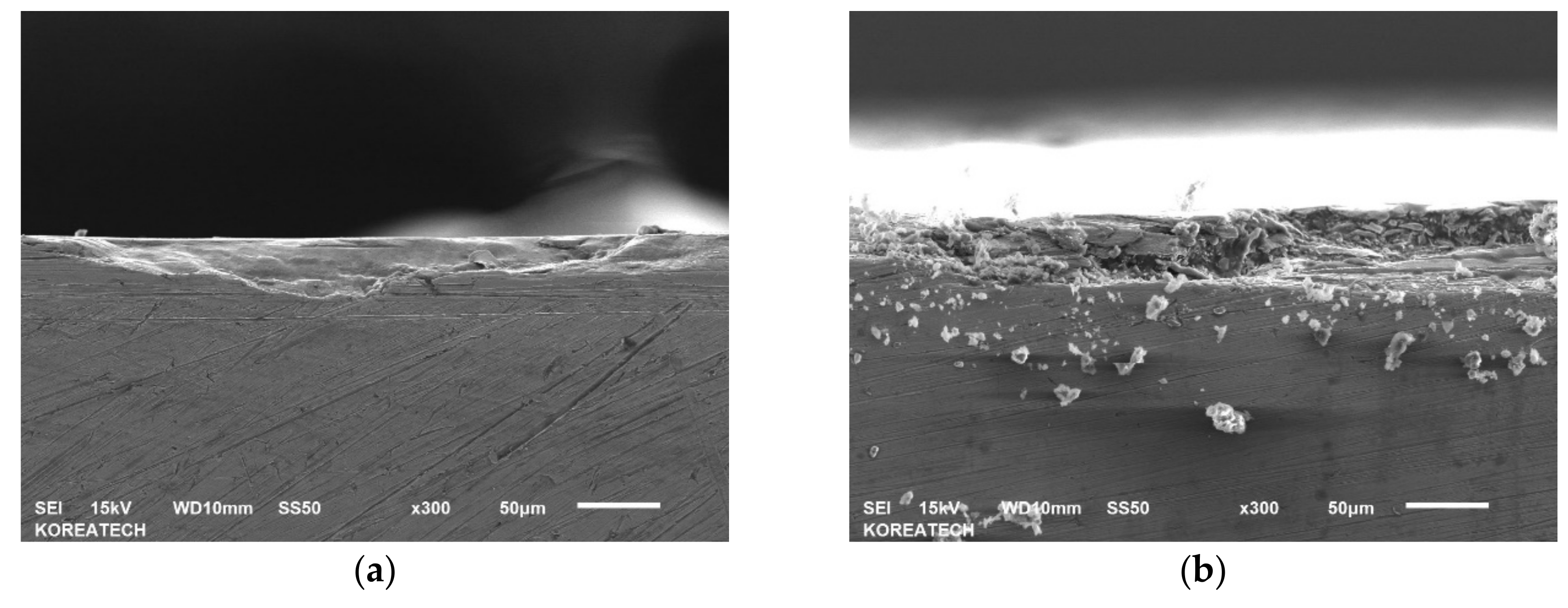
Figure 9.
Cross-sectional SEM images of the untreated #5NRB (1.150 × 10⁶ cycles) (a) and UNSM-treated #6NRB (1.544 × 10⁶ cycles) (b) specimens. Testing conditions: Equivalent stress −1600 MPa, rotation speed −1500 rpm, Fatigue cycles −10.
Figure 10.
SEM images of the untreated #9NRB (a) (4.338 × 10⁶ cycles) and UNSM-treated #10NRB (b) (7.380 × 10⁶ cycles) specimens.
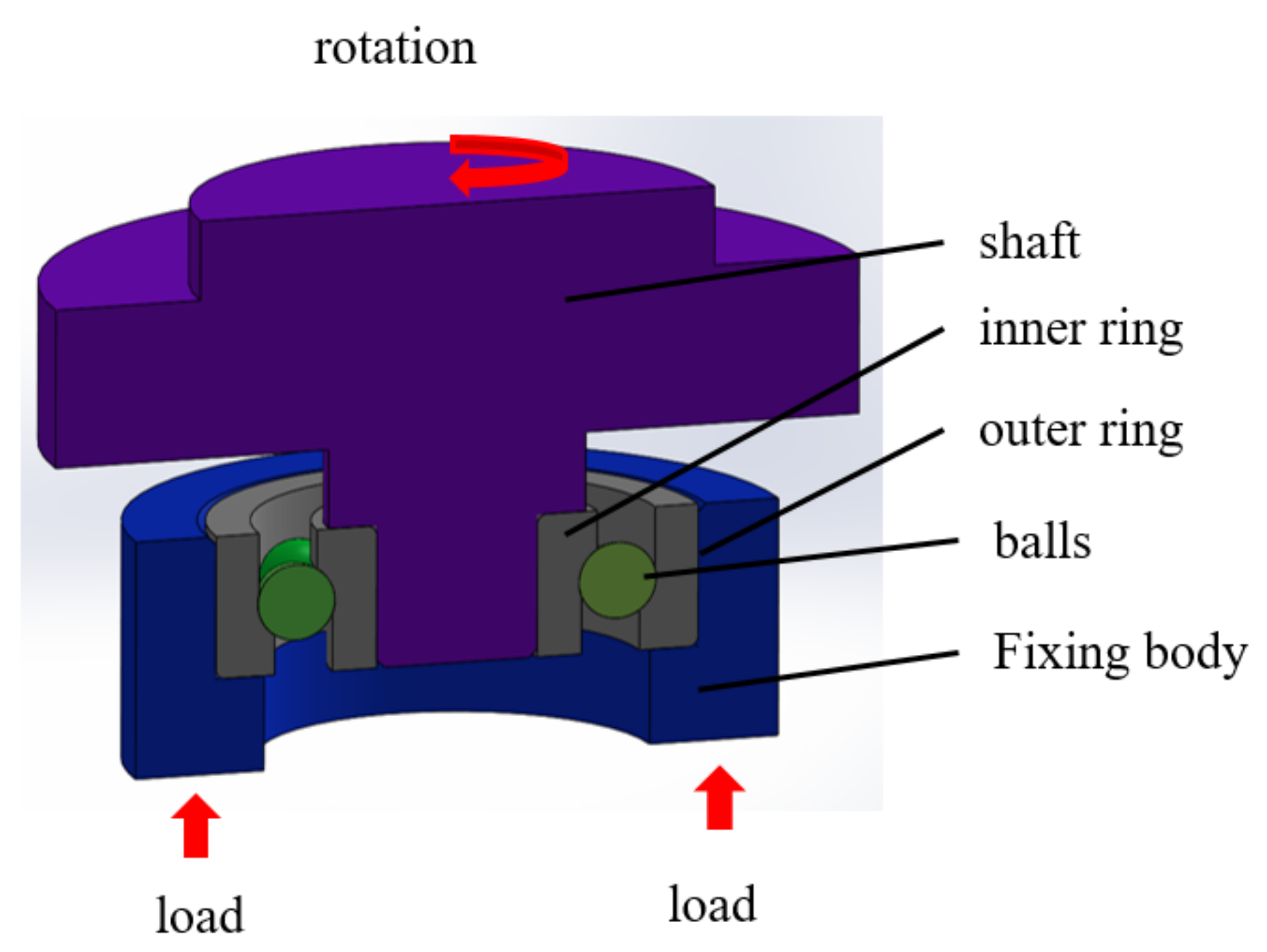
Figure 11.
Schematic view of an angular contact ball bearing fatigue test configuration.
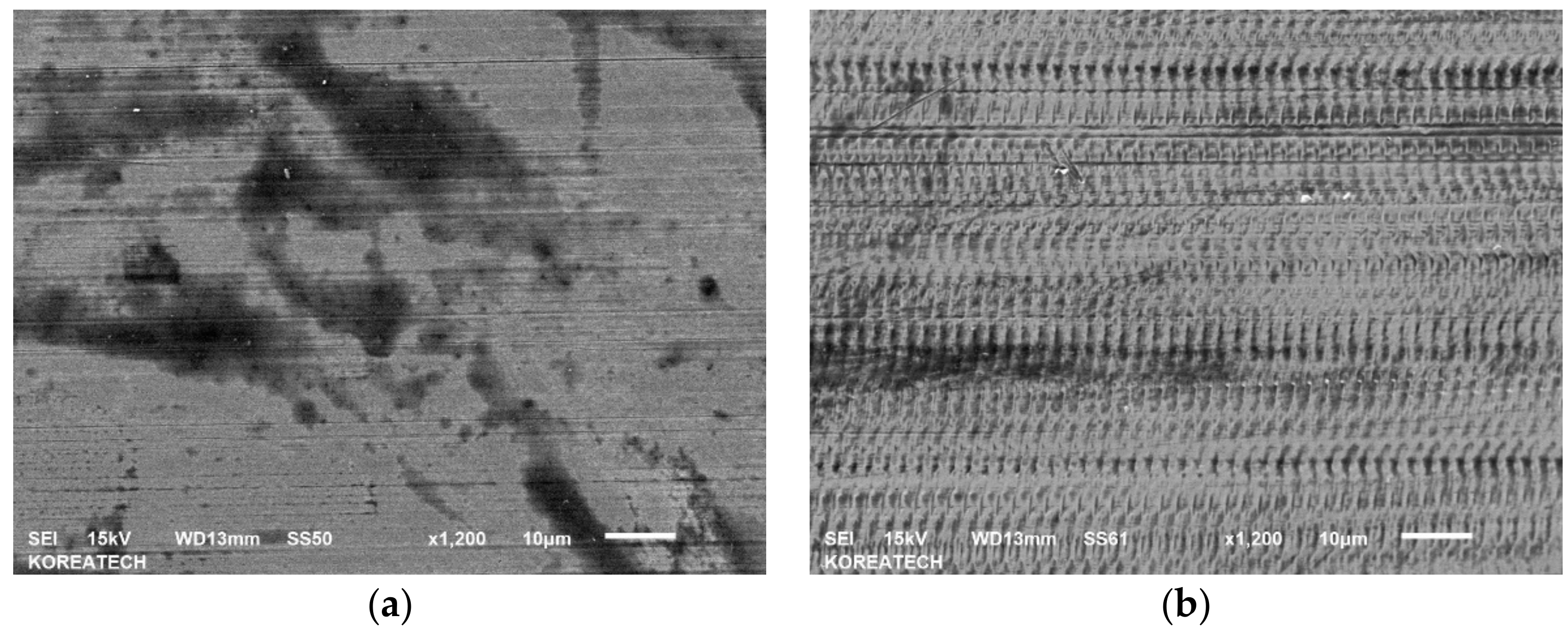
Figure 12.
SEM images of the untreated (a) and UNSM-treated (b) specimens.
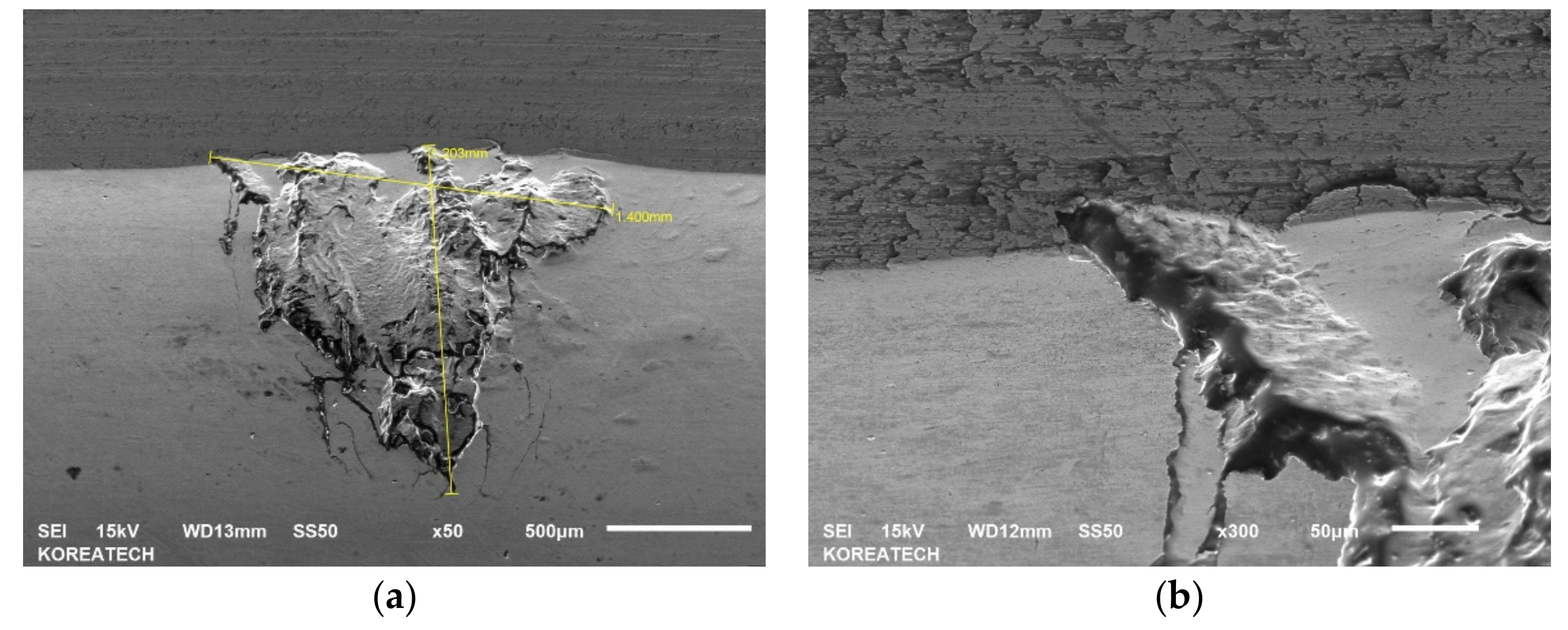
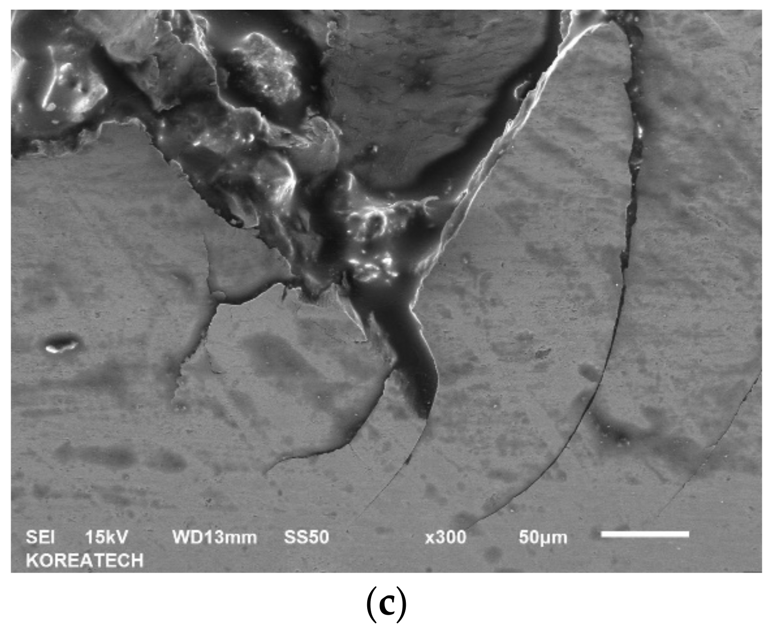
Figure 13.
Comparison of low (a) and high (b,c) SEM images of the damaged untreated specimens (11.175 × 10⁶ cycles). Testing conditions: Equivalent stress −1302 MPa, rotation speed −1000 rpm.
Table 1.
UNSM treatment process.
| Amplitude (µm) | Load (N) | Rotational Speed (rpm) | Feed (mm/rev) |
|---|
| 30 | 60 | 60 | 0.07 |
Table 2.
Specimen type and contact stress.
| Specimen Types | Contact Stress (Mpa) |
|---|
| #1NRB-untreated | 1770 |
| #2NRB-UNSM treatment |
| #3NRB-untreated | 1715 |
| #4NRB-UNSM treatment |
| #5NRB-untreated | 1600 |
| #6NRB-UNSM treatment |
| #7NRB-untreated | 1484 |
| #8NRB-UNSM treatment |
| #9NRB-untreated | 1355 |
| #10NRB-UNSM treatment |
Table 3.
Fatigue life test conditions.
| Rotational Speed (rpm) | Lubrication Conditions | Vibration Fatigue Setting Value |
|---|
| 1500 | Oil | 22 |
Table 4.
Comparison of the roughness and hardness of the specimens before and after UNSM treatment.
| Specimen | Roughness, (μm) | Hardness, (HRC) |
|---|
| Comparison | Before | After | Before | After |
|---|
| Specimen-A | 0.550 | 0.149 | 58 | 62 |
| Specimen-B | 0.477 | 0.150 | 58 | 62 |
Table 5.
Comparison of the residual stress of the inner bearing raceway before and after UNSM treatment.
| Comparison | Untreated (Mpa) | UNSM-Treated (Mpa) |
|---|
| Spherical roller bearing inner ring raceway | −54.44 | −1095.75 |
Table 6.
Dimensions and dynamic load of an angular contact ball bearing.
| d, mm | D, mm | B, mm | Dyn. Load, kN |
|---|
| 10 | 30 | 9 | 5.4 |
Table 7.
UNSM treatment parameters.
| Amplitude (µm) | Load (N) | Rotational Speed (rpm) | Feed (mm/rev) |
|---|
| 30 | 30 | 30 | 0.07 |
Table 8.
Bearing fatigue test conditions.
| Rotation Speed, rpm | Load, kN | Maximum Contact Pressure, MPa | Vibration Limit, G | Lubrication |
|---|
| 1000 | 3.5 | 2.764 | 22 | ISO VG 46 |
Table 9.
Comparison of the surface roughness and hardness of the specimens.
| Specimens | Hardness, HRC | Roughness, μm, Ra |
|---|
| #1ACB untreated | 61.5 | 0.052 |
| UNSM-treated | 64.2 | 0.033 |
Table 10.
Comparison of the fatigue cycles of the untreated and UNSM-treated specimens.
| Specimens | Cycles | Cause |
|---|
| #1ACB Untreated | 11,175,600 | inner ring raceway crack |
| #2ACB UNSM-treated | 14,527,800 | cage breakage |


