Improving the Reliability of Mechanical Components That Have Failed in the Field Due to Repetitive Stress


Abstract
:1. Introduction
2. Parametric Accelerated Life Testing
2.1. Setting an Overall Parametric ALT Plan
2.2. Parametric Accelerated Life Testing of Mechanical Systems
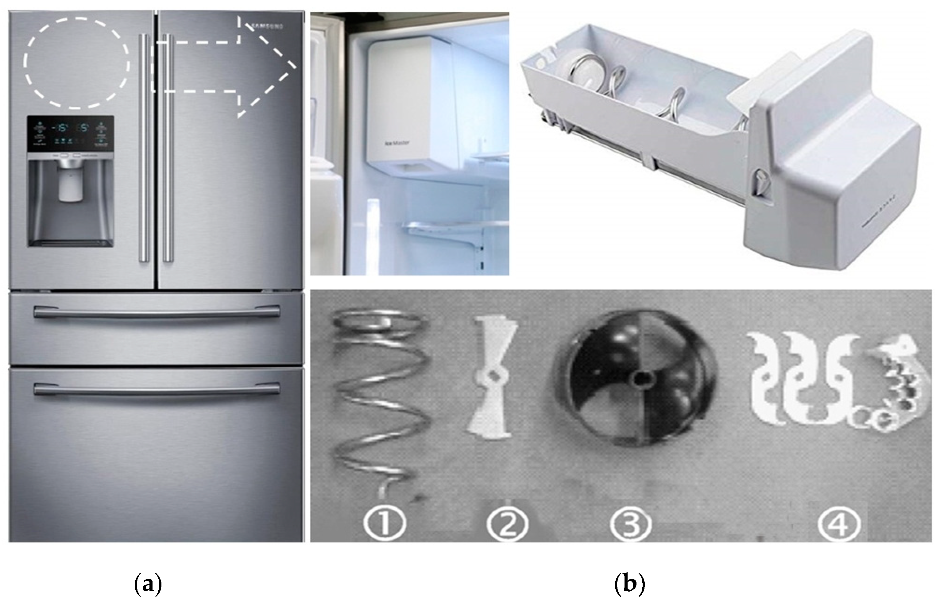
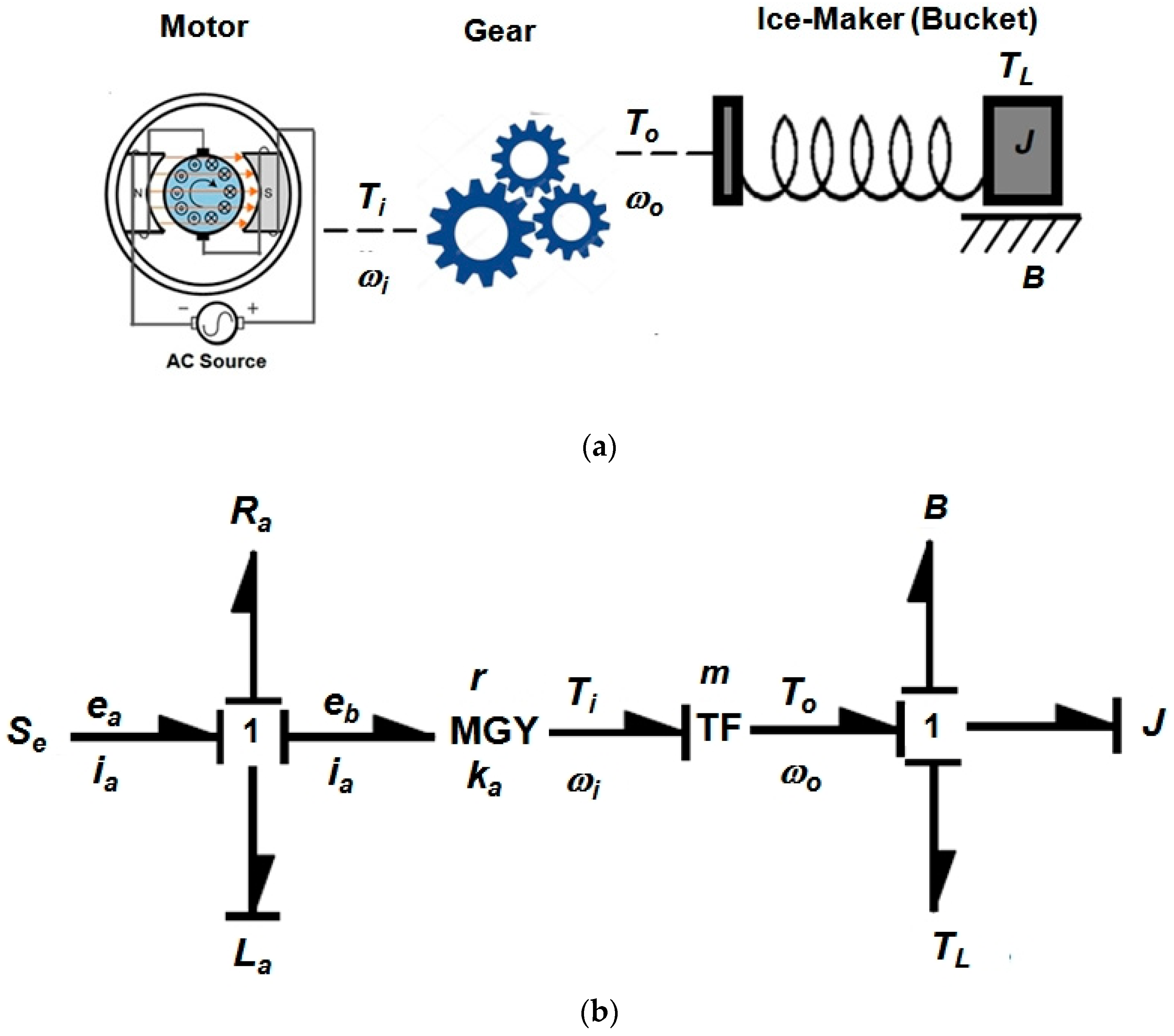
2.3. Case Study-Reliability Design of the Helix Upper Dispenser in an Ice-Maker
3. Results & Discussion
4. Conclusions
Author Contributions
Conflicts of Interest
Abbreviations
| B | viscous friction coefficient |
| BX | time which isan accumulated failure rate of X%, durability index |
| Ea | activation energy, eV |
| e | effort |
| ea | applied voltage, V |
| eb | counter-electromotive force |
| ef | field voltage, V |
| f | flow |
| Fc | ice crushing force, kN |
| F(t) | unreliability |
| h | testing cycles (or cycles) |
| h* | non-dimensional testing cycles, |
| ia | applied current, A |
| if | field current, A |
| J | momentum of inertia, kg m2 |
| k | Boltzmann’s constant, 8.62 × 10⁻⁵ eVdeg-1 |
| ka | constant of the counter-electromotive force |
| La | electromagnetic inductance |
| LB | target BX life and x = 0.01X, on the condition that x ≤ 0.2 |
| m | gear ratio |
| MGY | gyrator in causal forms for basic 2-ports and 3-ports |
| n | number of test samples |
| r | failed numbers |
| r | coefficient of gyrator |
| Ra | electromagnetic resistance |
| S | stress |
| ti | test time for each sample |
| T | torque, kN cm |
| TL | ice-crushing torque in bucket, kN cm |
| TF | time to failure |
| X | accumulated failure rate, % |
| x | x = 0.01X, on condition that x ≤ 0.2. |
| Greek symbols | |
| ω | angular velocity in ice bucket, rad/s |
| η | characteristic life |
| λ | cumulative damage exponent in Palmgren-Miner’s rule |
| Superscripts | |
| β | shape parameter in Weibull distribution |
| n | stress dependence, |
| Subscripts | |
| 0 | normal stress conditions |
| 1 | accelerated stress conditions |
References
- Magaziner, I.C.; Patinkin, M. Cold Competition: GE Wages the Refrigerator War. Harv. Bus. Rev. 1989, 89, 114–124. [Google Scholar]
- Bertsche, B. Reliability in Automotive and Mechanical Engineering: Determination of Component and System Reliability; Springer: Berlin, Germany, 2010. [Google Scholar]
- O’Connor, P.; Kleyner, A. Practical Reliability Engineering, 5th ed.; Wiley & Sons: Hoboken, NJ, USA, 2012. [Google Scholar]
- Toribio, J.; Lorenzo, M.; Vergara, D.; Aguado, L. The Role of Overloading on the Reduction of Residual Stress by Cyclic Loading in Cold-Drawn Prestressing Steel Wires. Appl. Sci. 2017, 7, 84. [Google Scholar] [CrossRef]
- Nie, B.; Zhao, Z.; Ouyang, Y.; Chen, D.; Chen, H.; Sun, H.; Liu, S. Effect of Low Cycle Fatigue Pre-damage on Very High Cycle Fatigue Behavior of TC21 Titanium Alloy. Materials 2017, 10, 1384. [Google Scholar] [CrossRef] [PubMed]
- Matsuishi, M.; Endo, T. Fatigue of metals subjected to varying stress. Jpn. Soc. Mech. Eng. 1968, 68, 37–40. [Google Scholar]
- Mottand Robert, L. Machine Elements in Mechanical Design, 4th ed.; Pearson Prentice Hall: Upper Saddle River, NJ, USA, 2004. [Google Scholar]
- Palmgren, A.G. Die Lebensdauer von Kugellagern Zeitschrift des Vereines Deutscher Ingenieure. Sci. Res. 1924, 68, 339–341. [Google Scholar]
- Taguchi, G. Off-line and on-line quality control systems. In Proceedings of the International Conference on Quality Control, Tokyo, Japan, October 1978. [Google Scholar]
- Taguchi, G.; Shih-Chung, T. Introduction to Quality Engineering: Bringing Quality Engineering Upstream; American Society of Mechanical Engineering: New York, NY, USA, 1992. [Google Scholar]
- Ashley, S. Applying Taguchi’s quality engineering to technology development. Mech. Eng. 1992, 114, 58. [Google Scholar]
- Wilkins, J. Putting Taguchi Methods to Work to Solve Design Flaws. Qual. Prog. 2000, 33, 55–59. [Google Scholar]
- Phadke, M. Quality Engineering Using Robust Design; Englewood Cliffs: Prentice Hall, NJ, USA, 1989. [Google Scholar]
- Byrne, D.; Taguchi, S. The Taguchi approach to parameter design. Qual. Prog. 1987, 20, 19–26. [Google Scholar]
- IEEE Standard Glossary of Software Engineering Terminology, IEEE Std 610.12-1990; Standards Coordinating Committee of the Computer Society of IEEE: New York, NY, USA, 1990.
- Klutke, G.; Kiessler, P.C.; Wortman, M.A. A critical look at the bathtub curve. IEEE Trans. Reliab. 2015, 52, 125–129. [Google Scholar] [CrossRef]
- Duane, J.T. Learning Curve Approach to Reliability Monitoring. IEEE Trans. Aerosp. 1964, 2, 563–566. [Google Scholar] [CrossRef]
- Kreyszig, E. Advanced Engineering Mathematics, 9th ed.; John Wiley and Son: Hoboken, NJ, USA, 2006; p. 683. [Google Scholar]
- Woo, S.; O’Neal, D. Reliability Design of Mechanical Systems Subject to Repetitive Stresses. Recent Patents Mech. Eng. 2015, 8, 222–234. [Google Scholar] [CrossRef]
- Woo, S.; O’Neal, D.; Pecht, M. Improving the reliability of a water dispenser lever in a refrigerator subjected to repetitive stresses. Eng. Fail. Anal. 2009, 16, 1597–1606. [Google Scholar] [CrossRef]
- Woo, S.; O’Neal, D.; Pecht, M. Design of a Hinge kit system in a Kimchi refrigerator receiving repetitive stresses. Eng. Fail. Anal. 2009, 16, 1655–1665. [Google Scholar] [CrossRef]
- Woo, S.; O’Neal, D.; Pecht, M. Failure analysis and redesign of the evaporator tubing in a Kimchi refrigerator. Eng. Fail. Anal. 2010, 17, 369–379. [Google Scholar] [CrossRef]
- Zhao, F.; Ding, X.; Fan, X.; Cui, R.; Li, Y.; Wang, T. Contact Fatigue Failure Analysis of Helical Gears with Non-Entire Tooth Meshing Tests. Metals 2018, 8, 693. [Google Scholar] [CrossRef]
- Hamandi, F.; Laughlin, R.; Goswami, T. Failure Analysis of PHILOS Plate Construct Used for Pantalar Arthrodesis Paper II—Screws and FEM Simulations. Metals 2018, 8, 279. [Google Scholar] [CrossRef]
- Alqedairi, A.; Alfawaz, H.; Rabba, A.; Almutairi, A.; Alnafaiy, S.; Mohammed, M.K. Failure Analysis and Reliability of Ni–Ti-Based Dental Rotary Files Subjected to Cyclic Fatigue. Metals 2018, 8, 36. [Google Scholar] [CrossRef]
- Cao, X.; Xu, L.; Xu, X.; Wang, Q. Fatigue Fracture Characteristics of Ti6Al4V Subjected to Ultrasonic Nanocrystal Surface Modification. Metals 2018, 8, 77. [Google Scholar] [CrossRef]
- Nagarajan, V.; Putatunda, S.; Boileau, J. Fatigue Crack Growth Behavior of Austempered AISI 4140 Steel with Dissolved Hydrogen. Metals 2017, 7, 466. [Google Scholar] [CrossRef]
- Zhang, W.; Wang, H.; Zhang, J.; Dai, W.; Huang, Y. Brittle Fracture Behaviors of Large Die Holders Used in Hot Die Forging. Metals 2017, 7, 198. [Google Scholar] [CrossRef]
- Alvarez, J.; Lacalle, R.; Arroyo, B.; Cicero, S.; Gutiérrez-Solana, F. Failure Analysis of High Strength Galvanized Bolts Used in Steel Towers. Metals 2016, 6, 163. [Google Scholar] [CrossRef]
- Persaud-Sharma, D.; Budianaky, N.; McGoron, A. Mechanical Properties and Tensile Failure Analysis of Novel Bio-absorbable Mg-Zn-Cu and Mg-Zn-Se Alloys for Endovascular Applications. Metals 2013, 3, 23–40. [Google Scholar] [CrossRef] [PubMed]
- Hojna, A. Overview of Intergranular Fracture of Neutron Irradiated Austenitic Stainless Steels. Metals 2017, 7, 392. [Google Scholar] [CrossRef]
- Badnava, H.; Etamadi, E.; Msekh, M. A Phase Field Model for Rate-Dependent Ductile Fracture. Metals 2017, 7, 180. [Google Scholar] [CrossRef]


| Modules | Market Data | Expected Reliability | Targeted Reliability | |||||
|---|---|---|---|---|---|---|---|---|
| Yearly Failure Rate, %/year | Bx Life, year | Yearly Failure Rate, %/year | Bx Life, year | Yearly Failure Rate, %/year | Bx Life, year | |||
| A | 0.35 | 2.9 | Similar | ×1 | 0.35 | 2.86 | 0.10 | 10(x = 1.0) |
| B | 0.24 | 4.2 | New | ×5 | 1.20 | 0.83 | 0.15 | 10(x = 1.5) |
| C | 0.30 | 3.3 | Similar | ×1 | 0.30 | 3.33 | 0.10 | 10(x = 1.0) |
| D | 0.31 | 3.2 | Modified | ×2 | 0.62 | 1.61 | 0.10 | 10(x = 1.0) |
| E | 0.15 | 6.7 | Modified | ×2 | 0.30 | 3.33 | 0.15 | 10(x = 1.5) |
| Others | 0.50 | 2.0 | Similar | ×1 | 0.50 | 2.00 | 0.40 | 10(x = 4.0) |
| Product | 1.9 | 5.4 | - | - | 3.27 | 3.06 | 1.00 | 10(x = 10) |
| Parametric ALT | 1st ALT | 2nd ALT | 3rd ALT |
|---|---|---|---|
| Initial Design | Second Design | Final Design | |
| Over the course of 42,000 cycles, the helix upper dispenser has no problems | 170 cycles: 1/10 fracture 5200 cycles: 1/10 fracture 7880cycles: 2/10 fracture 8880cycles: 2/10 fracture 11,600 cycles: 4/10 fracture | 17,000 cycles: 1/6 fracture 25,000 cycles: 3/6 fracture 28,000 cycles: 1/6 fracture 38,000 cycles: 1/6 fracture | 42,000 cycles: 6/6 OK 75,000 cycles: 6/6 OK |
| Helix structure |  |  | - |
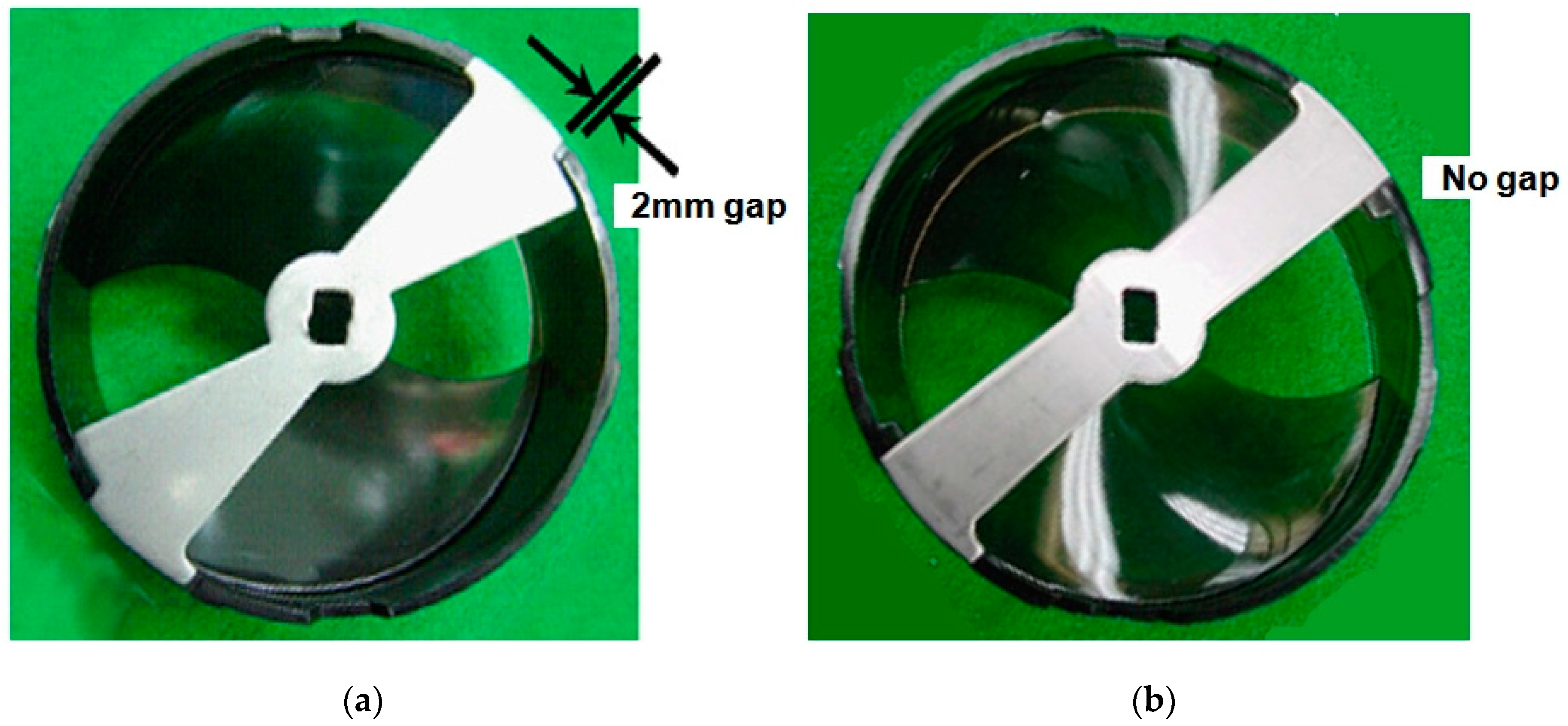
| Material and specification | C1: Gap of 2 mm → 0 mm | C2: Added rib on the outside of helix | - |
© 2019 by the authors. Licensee MDPI, Basel, Switzerland. This article is an open access article distributed under the terms and conditions of the Creative Commons Attribution (CC BY) license (http://creativecommons.org/licenses/by/4.0/).
Share and Cite
Woo, S.; O’Neal, D.L. Improving the Reliability of Mechanical Components That Have Failed in the Field Due to Repetitive Stress. Metals 2019, 9, 38. https://doi.org/10.3390/met9010038
Woo S, O’Neal DL. Improving the Reliability of Mechanical Components That Have Failed in the Field Due to Repetitive Stress. Metals. 2019; 9(1):38. https://doi.org/10.3390/met9010038
Chicago/Turabian StyleWoo, Seongwoo, and Dennis L. O’Neal. 2019. "Improving the Reliability of Mechanical Components That Have Failed in the Field Due to Repetitive Stress" Metals 9, no. 1: 38. https://doi.org/10.3390/met9010038