Article

Effect of Carbides on Thermos-Plastic and Crack Initiation and Expansion of High-Carbon Chromium-Bearing Steel Castings

College of Metallurgy and Energy, North China University of Science and Technology, 21 Bohai Street, Tangshan 063210, China
*
Authors to whom correspondence should be addressed.
Metals 2024, 14(3), 335; https://doi.org/10.3390/met14030335
Submission received: 18 February 2024 / Revised: 7 March 2024 / Accepted: 8 March 2024 / Published: 14 March 2024
(This article belongs to the Special Issue Fracture Mechanics of Metals)

Abstract

:
The bearing steel’s high-temperature brittle zone (1250 °C–1100 °C), second brittle zone (1100 °C–950 °C), and low-temperature brittle zone (800 °C–600 °C) were determined by the reduction in area and true fracture toughness. The crack sensitivity was strongest at temperatures of 1200 °C, 1000 °C, and 600 °C, respectively. Various experimental and computational methods were used to establish the phase type, microstructure, size, and mechanical properties of carbides in bearing steel. The critical conditions for crack initiation in the matrix (FCC-Fe, FCC-Fe, and BCC-Fe)/carbides (striped Fe0.875Cr0.125C, netted Fe2.36Cr0.64C, and spherical Fe5.25Cr1.75C3) were also investigated. The values for the high-temperature brittle zone, the second brittle zone, and the low-temperature brittle zone were 13.85 MPa and 8.21 × 10⁻³, 4.64 MPa and 6.52 × 10⁻³, and 17.86 MPa and 1.86 × 10⁻², respectively. These were calculated using Eshelby’s theory and ABAQUS 2021 version software. The ability of the three carbides to cause crack propagation was measured quantitatively by energy diffusion: M3C > MC > M7C3. This study analyzed the mechanism of carbide precipitation on the formation of high-temperature cracks in bearing steel casting. It also provided the critical conditions for carbide/matrix interface cracks in bearing steel continuous casting, thus providing effective support for improving the quality of bearing steel casting.

1. Introduction

High-carbon chromium-bearing steel is characterized by high hardness, high fatigue performance, and high wear resistance and is widely used in emerging industries such as precision equipment [1], wind power generation [2], high-speed railways [3], and aerospace applications [4]. The high hardness and wear resistance of bearing steel can be achieved by solid solution strengthening of carbon and precipitation strengthening of carbide [5], and excellent wear resistance can be achieved by adding chromium and microalloying elements [6].
However, the alloying element content of carbon and chromium in the high-carbon chromium-bearing steel was high, and many primary carbides precipitated during the solidification process. The stress concentration of the casting was easily caused by the carbides, which reduced the high-temperature toughness of the high-carbon chromium-bearing steel when the hardness of the primary carbides was significantly higher than that of the matrix and the size of the carbides was greater than 40 μm. In addition, primary carbides can induce subsurface cracks during the service process of bearing steel [7], thereby reducing the fatigue life of high-carbon chromium-bearing steel. Several studies have shown that the formation of subsurface cracks in high-carbon chromium-bearing steel is usually related to the crystal structure, mechanical properties, and microscopic morphology of the primary carbide. Sharma [8] showed that the enrichment of Cr, Mo, and V could coarsen M7C3 carbides, leading to an increase in the probability of trans-granular fracture. A study by S. Lee [9] on the micro-fracture process of low-carbon stainless steel showed that the cracks in bearing steel first originate at the edge of large M3C carbides or form pores at the matrix/carbide interface to induce cracks. Therefore, reasonable control of the carbide size and solute elements will effectively improve the product quality of high-carbon chromium-bearing steel.
Many researchers have modified and dissolved carbides in bearing steel castings through alloying and heat treatment. For example, adding Nb to bearing steel suppressed the precipitation of network carbides, thereby reducing the thickness of network carbides. When 0.04% Nb was added, the average thickness of the network carbide decreased by 27% [10]. However, adding Nb increased the hardness of the primary carbides, causing cracks in the bearing steel during the rolling process. Therefore, the relationship between adding Nb and reducing the sensitivity of bearing steel to cracks was not clear. In addition, the carbides in the bearing steel casting were dissolved through long-term insulation and high austenitizing temperatures [11,12,13,14]. However, even the coarse carbides formed during the solidification process after heat treatment cannot meet the performance requirements of high-quality bearing steel.
To reduce the influence of primary carbides on the crack sensitivity of casting materials, the precipitation process of primary carbides during bearing steel continuous casting has been studied by many researchers. Refs. [15,16,17] have shown that the formation of primary carbides is caused by solute segregation at the end of solidification. During the continuous casting process, due to the cooling imbalance between the crystalline and secondary cooling sections, solid-liquid phase convection occurred, leading to severe segregation and carbide precipitation. Moreover, the stress applied during the secondary cooling process causes a slight deformation of the casting, causing tensile stress on the surface of the casting and resulting in cracks. To control the initiation and propagation of cracks during casting, numerous researchers have optimized continuous casting process parameters, including superheating [18], casting speed [19,20], electromagnetic stirring [21,22], soft reduction [23,24], and coordinated control technology involving electromagnetic stirring and soft reduction [25]. Electromagnetic stirring has a significant impact on solidification segregation. Jiang used electromagnetic stirring equipment to reduce the degree of C segregation during the solidification process, resulting in a uniform distribution of carbides during casting [26]. The precipitation of network carbides and banded carbides during the continuous casting process was effectively reduced using M+F-EMS+MSR technology [27]. Although the refinement method for primary carbides during the solidification process of bearing steel has improved, cracking during casting still cannot be controlled. At present, there are few reports on the casting crack sensitivity of primary carbides in high-carbon chromium-bearing steels, especially on the study of the mechanical properties of high-carbon chromium-bearing steel carbides under critical conditions for casting crack initiation.
Therefore, this work used a combination of first-principle calculations and experimental methods to study the impact of carbide precipitation behavior on the critical conditions and fracture processes of crack initiation and propagation in high-carbon chromium-bearing steels. In this study, the brittle range and crack sensitivity temperature were first determined by a Gleeble thermal-testing machine and a crack sensitivity analysis model during the solidification process of high-carbon chromium-bearing steel. Second, the casting fracture morphology, carbide phase types, and microscopic morphology were analyzed via optical microscopy (OM), scanning electron microscopy (SEM), energy dispersive spectrometry (EDS), and X-ray diffraction (XRD) at different characteristic temperatures. In addition, carbide precipitation behavior and mechanical properties were calculated by Thermo-Calc thermodynamic calculation software (2019b, Thermo-Calc Software AB, Solna, Sweden) and Materials Studio calculation software (8.0, Accelrys, San Diego, CA, USA), and irregular carbides were systematically characterized based on fractal dimension. Finally, the critical conditions and fracture process of matrix/carbide interface cracking were calculated by the Eshelby inclusion theory and ABAQUS 2021 version simulation software (2021, SIMULIA, Paris, France). This study provided a comprehensive understanding of the initiation of casting cracks induced by carbide precipitation during the solidification process of high-carbon chromium-bearing steels.

2. Experimental Materials and Methods

2.1. Experimental Materials

The GCr15 bearing steel slab was produced by an iron and steel enterprise as the experimental material. The production process involved continuous blast furnace-converter-LF-RH casting. The chemical composition of high-carbon chromium-bearing steel is shown in Table 1.

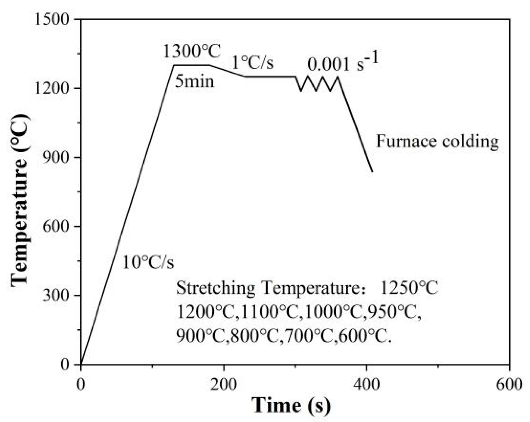
2.2. Thermo-Mechanical Tests

The thermo-mechanical test was conducted based on the Gleeble-3500 instrument under temperature simulation and experimental data design during the continuous casting process of bearing steel [28]. The temperature range selected for the experiment was 1250 °C–600 °C, including the entire continuous casting process. Under the process conditions of the bending continuous casting machine, the stress effect of the roller on the casting shell and the stress effect during the casting straightening process were considered, so the strain rate was set to 0.001 s−1 in the thermal-mechanical test. Firstly, the cylindrical sample with a diameter of 6 mm and a specified length of 12 mm was processed by the bearing steel casting. Secondly, the tensile sample was heated to 1300 °C at a rate of 10 °C/s using the Gleeble-3500 thermo-mechanical machine and kept for 5 min to ensure the dissolution of the original carbides. The sample was directly heated by a K-type thermocouple connected to the power supply. Then, the sample was cooled at the cooling rate of 1 °C/s to 1250 °C, 1200 °C, 1100 °C, 1000 °C, 950 °C, 900 °C, 800 °C, 700 °C, and 600 °C, and then subjected to uni-axial tension. The experimental plan is shown in Figure 1, and the stress–strain flow curve was recorded in real-time by sensors in the thermal-mechanical machine.

2.3. Microscopic Morphology of Tensile Fractures and Carbides

The fracture surface of the tensile sample was cut by a wire-cutting machine. This process generates samples, which are mounted, ground with abrasive paper, and polished with diamond and silica colloidal suspensions as a final step. After polishing, the samples were etched with a 10% Nital solution. The fracture morphology and carbide microstructure were characterized by a metallographic microscope (DMI8C, Leica, Heidelberg, Germany), a scanning electron microscope (Quanta 650, FEI, Hillsboro, OR, USA), and an energy dispersive spectrometer (EDS, FEI, Hillsboro, OR, USA). The types of carbide phases in different brittle regions were determined by X-ray diffraction (D/MAX2500PC, Rigaku, Toyota, Japan), with the scanning range and scanning speed set to 5°~105° and 2 °/min, respectively. The equivalent size and fractal dimension of the carbides in the different brittle regions were quantified by Image Pro Plus image processing software (6.0, Media Cybernetics, Silver Spring, MD, USA).

2.4. Thermodynamic Calculation of Carbides

The solidification process and equilibrium phase diagram of high-carbon chromium-bearing steel were calculated by the Scheil module and the TCFE9 database in Thermo-Calc thermodynamic 2019b version calculation software. The calculation temperature was set at 200–1600 °C, and the gas pressure was set at 1.0 × 10⁵ Pa.

2.5. Calculation of Mechanical Properties of Carbides

The elastic moduli of the matrix (FCC-Fe and BCC-Fe) and carbides (MC, M3C, and M7C3) in the high-carbon chromium-bearing steel were calculated by the CASTEP module in Materials Studio 8.0 version software based on density functional theory. The calculation adopted the WC algorithm in generalized gradient approximation (GGA). The cutoff energies of FCC-Fe, BCC-Fe, MC M3C, and M7C3 were set to 390 eV, 390 eV, 440 eV, 440 eV, and 440 eV, respectively. The k-points were set to 13 × 13 × 13, 7 × 7 × 7, 6 × 6 × 6, 5 × 4 × 6, and 2 × 2 × 6, and the cutoff energy and the k-point settings were obtained through convergence testing.
To quantitatively study the mechanical properties of the matrix and carbides of high-carbon chromium-bearing steels, the bulk modulus (B), shear modulus (G), Young’s modulus (E), and Poisson’s ratio (v) of the matrix and carbides were calculated based on Hooke’s law [29,30] and the Voigt–Reuss–Hill model. The bulk modulus (B) reflects the ability of matter to resist bond length, while the shear modulus (G) reflects the ability of matter to resist bond angle; thus, the B/G (class) ratio is commonly used to compare the brittle plasticity of materials. A material with a B/G value less than 1.75 was considered brittle, and a material with a value greater than 1.75 was considered plastic [30]. The calculation formulas were as follows.
Cubic structure (FCC-Fe, BCC-Fe, and MC):
B = 1 3 C 11 + C 12
G = 1 5 C 11 C 12 + 3 C 44
E = 9 B G ( 3 B + G )
v = 3 B 2 G 2 ( 3 B + G )
Orthogonal and hexagonal structures (FCC-Fe, BCC-Fe, and MC):
B = 1 9 C 11 + C 22 + C 33 + 2 9 C 12 + C 13 + C 23
G = 1 15 C 11 + C 22 + C 33 C 12 C 13 C 23 + 1 5 C 44 C 55 + C 66
E = 9 B G ( 3 B + G )
v = 3 B 2 G 2 ( 3 B + G )
where Cij are elasticity constants, B is the modulus of the volume, G is the shear modulus, E is the Young’s modulus, and v is the Poisson’s ratio.

2.6. Simulation of Crack Initiation at Matrix/Carbide Interface

To verify the critical stress and critical strain of the matrix/carbide interface crack in the brittle region, the fracture process of the matrix/carbide interface in different brittle regions was simulated by using the extended finite element method (XFEM) in ABAQUS finite element 2021 version software based on the stress–strain curve of thermos-mechanical tests. The matrix/carbide model grid unit was set as a quadrilateral CPS4R unit, the cohesive force unit was set as a COH2D4 unit, and the carbide interface unit was refined. In addition, to highlight the impact of the mechanical properties of carbides on the matrix, the carbides and the matrix were subjected to elastic deformation and elastic-plastic deformation, respectively, during the stretching process.

3. Results and Discussion

3.1. Sensitivity Analysis of Cracks in Casting

Thermo-mechanical tests are commonly used to study the crack sensitivity of casting materials. The stress and cooling conditions of the casting during the secondary cooling process and straightening section could be accurately simulated by a Gleeble-3500 thermo-mechanical machine. The reduction in area (R.A.) was usually defined as the standard for the high-temperature thermoplastic range [31], and the lower the reduction in area was, the worse the thermoplastic. R.A. value of 60% was used as the standard for judging the brittle range [32], and the calculation of the reduction in area is shown in Equation (9):
R . A = 1 A f A 0 × 100 %
where R.A. is the reduction in area, A0 is the initial cross-sectional area of the round specimen (mm2), and Af is the final cross-sectional area after failure (mm2).
In addition, the judgment criteria for R.A. considered only the changes in the cross-sectional fracture before and after stretching, and the necking surface was considered to have a planar circular shape, which caused the actual situation of the fracture surface to be ignored, resulting in an overestimation of the minimum value of R.A [33]. However, to fully consider the transient behavior of fracture and the temperature with the strongest crack sensitivity in different brittle regions, the temperature with the strongest crack sensitivity described by the true fracture ductility and true fracture strength parameters had to be in different brittle regions.
The true fracture ductility and true fracture strength were based on the stress–strain curve to calculate the real strain and real stress of the transient behavior of fracture of the tensile sample after necking [34], respectively. The calculation method is shown in Equations (10) and (11):
= l n A 0 A f = ln ( 1 1 R . A )
δ = A 0 A f δ f = ( 1 1 R . A ) δ f
where is the true fracture ductility, δ is the true fracture strength (MPa), and δ f is the fracture strength point from the engineering flow curve (MPa).
The results of the analysis of the R.A. and ultimate tensile strength of the samples at different temperatures are shown in Figure 2. The experimental results revealed that the high-temperature brittleness range, second brittleness range, and low-temperature brittleness range of the high-carbon chromium-bearing steel casting were 1250 °C–1100 °C, 1100 °C–950 °C, and 800 °C–600 °C, respectively. The temperature range of the plastic zone was 950 °C–800 °C, and 1100 °C was considered the optimal temperature for high-temperature plastic. In addition, the ultimate tensile strength of the casting increased with decreasing continuous casting temperature. When the continuous casting temperature was less than 800 °C, phase transformation and solidification structure transformation were the reasons for the rapid increase in the ultimate tensile strength. Usually, an increase in the ultimate tensile strength of a casting is caused by the refinement of the solidification structure [32].
The calculation results of the true fracture strength and true fracture ductility of the sample at the continuous casting temperature are shown in Figure 2b. The results showed that the true fracture strength increased with decreasing continuous casting temperature but decreased with decreasing temperature within the ranges 1250 °C–1200 °C and 1100 °C–1000 °C. Therefore, the true fracture strength reached the minimum and maximum values at 1000 °C and 600 °C, indicating that the tensile sample underwent the minimum and maximum true stresses when fractured at 1000 °C and 600 °C, respectively. Moreover, in the high-temperature brittle zone, the true fracture toughness decreased from 0.78 to 0.68 and then increased to 0.95, reaching a minimum at 1200 °C. In the second brittle zone, with decreasing temperature, the true fracture ductility first decreased and then increased, reaching a minimum value of 0.044 at 1000 °C. The true fracture ductility in the low-temperature brittle zone decreased with decreasing temperature, reaching a minimum value of 0.088 at 600 °C. Therefore, the true strain of the high-carbon chromium-bearing steel casting was the smallest, and the crack sensitivity was the strongest at 1200, 1000, and 600 °C.

3.2. Microscopic Morphology of Tensile Fractures and Carbides

To analyze the fracture mode and characteristics of the bearing steel casting under a continuous casting temperature, cross-sections and sections of the tensile pattern were characterized via SEM at the characteristic temperature, which exhibited the strongest crack sensitivity in different brittle regions, and the microstructures of the carbides near the fracture surface were also characterized via SEM. The fracture morphology and carbide microstructure at characteristic temperatures of 1200, 1000, and 600 °C are shown in Figure 3. From Figure 3A1–A3, a slight “necking” phenomenon was observed in the tensile sample, with some dimples and local cleavage phenomena observed in the high-temperature brittle zone of the cross-section fracture at 1200 °C. Both intergranular and transgranular fractures were observed simultaneously, and stripe carbides and massive carbides were found in the high-temperature brittle zone. Crack initiation and extension were carried out in the direction of carbide growth.
From Figure 3B1–B3, the fracture surface of the tensile specimen was not only flat but also had some shallow and small dimples at 1000 °C. Therefore, the second brittle zone was considered to fracture via brittle fracture. In addition, a large amount of carbide enrichment was observed, and crack extension occurred along the matrix/carbide interface in the second brittle zone. From Figure 3C1–C3, the tensile sample exhibited a serrated and rock sugar-like fracture morphology, with obvious river traces and grain boundaries clearly displayed on the cross-section fracture at 600 °C. Therefore, the low-temperature brittle zone was considered a typical intergranular fracture. In addition, cracks often formed at trigeminal grain boundaries, and small granular carbides were found near cracks in the low-temperature brittle zone. The fracture mode of the sample was determined by the size of the dimples, and the carbides in the steel were often considered the nucleation source of the dimples [35,36]. Therefore, the fracture mode of the casting in different brittle regions was directly determined by the type and microstructure of the carbides.
To determine the types and microstructures of carbides in different brittle zones, the carbide phase was not only characterized via XRD but also characterized via SEM in different brittle zones, and the material composition of the carbides was also determined via EDS.
The phase types and microstructures of the carbides within different brittle zones are shown in Figure 4 and Figure 5, respectively. The carbides in the high-temperature brittle zone were mainly face-centered cubic (FCC) MC (Fe0.875Cr0.125C), whose lattice constant was 7.2 Å × 7.2 Å × 7.2 Å. The micromorphology of the MC is shown in Figure 5a as a strip, which was a type of Fe-rich carbide. The carbides in the second brittle zone were mainly FCC-MC (Fe0.875Cr0.125C) and an orthogonal structure (Pnma) M3C (Fe2.36Cr0.64C), and the lattice constant of M3C was 5.08 Å × 6.73 Å × 4.52 Å. The micromorphology of M3C is shown in Figure 5b as a net, which was a type of Cr-rich carbide. The carbides in the low-temperature brittle zone were mainly FCC-MC (Fe0.875Cr0.125C) and M7C3 (Fe5.25Cr1.75C3) with hexagonal structures (P63mc). The lattice constant of M7C3 was 13.805 Å × 13.805 Å × 4.498 Å, and the micromorphology of M7C3 is shown in Figure 5c as a sphere. To investigate the fracture mechanisms of the different brittle zones, the precipitation behavior, size, and mechanical properties of the carbides also need to be determined.

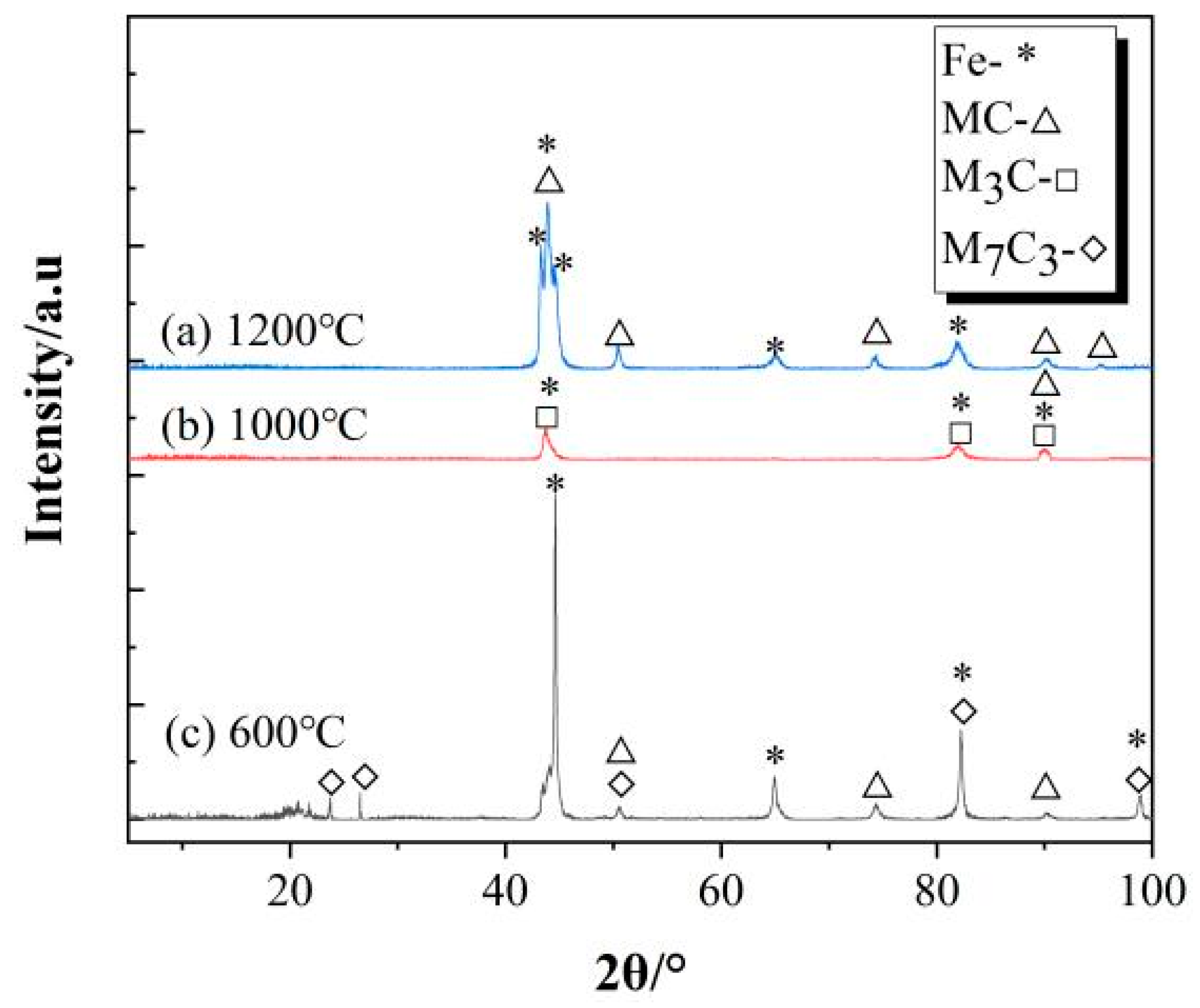
3.3. Analysis of Precipitates and Mechanical Properties of Carbides

The precipitation behavior of carbides at different brittle intervals was determined. The solidification path and equilibrium phase diagram of the high-carbon chromium-bearing steel were calculated using the TCFE9 database of the Thermo-Calc 2019b version software, as shown in Figure 6. In the process of using Thermo-Calc, not only were all chemical components of the high-carbon chromium-bearing steel inputted, but all possible precipitates in the equilibrium phase diagram were selected to prevent artificial errors in the calculation results. In the high-temperature brittle zone, the steel liquid gradually solidified. When the solid phase ratio was 0.92, the primary carbide MC precipitated in the residual liquid phase and FCC phase, and the precipitation temperature was 1158 °C. The solute elements at the end of solidification were enriched, thus promoting the precipitation of primary carbides. In addition, primary carbides nucleated at the austenite grain boundary and at the front of the solid-liquid phase, which were solute enrichment areas [15]. In the second brittle zone, M3C carbides precipitated in the FCC-Fe phase at a precipitation temperature of approximately 900 °C. When the concentration of C exceeded the solubility in the FCC-Fe phase, M3C carbides precipitated [37]. In the low-temperature brittle zone, M7C3 precipitated from BCC-Fe at a temperature of approximately 600 °C. When the solubility of C in the BCC-Fe reached saturation, M7C3 carbides precipitated at the grain boundaries [38].
The difference between the calculated and experimental carbide precipitation temperatures was calculated because the Thermo-Calc calculation was an equilibrium calculation and because the experiment was conducted at a strain rate of 0.001 s−1. The migration rate of carbon atoms in the sample accelerated under stress, leading to a decrease in the nucleation barrier of the carbides, thereby promoting the precipitation of the carbides [39,40]. In addition, the order of carbide precipitation calculated by Thermo-Calc was consistent with the experimental results, so the Thermo-Calc calculation still has explanatory significance.
To determine the size of the carbides in different brittle regions during the continuous casting process, the areas of carbides in multiple fields of view were counted using IPP software (6.0, Media Cybernetics, Silver Spring, MD, USA) at different characteristic temperatures, and the selected fields of view were all near the fracture. Due to the irregular shapes of the three types of carbides, the equivalent diameter of the carbides was determined using the area of the carbides, and the calculation formula is shown in Equation (12) [41]:
D = 4 A π
where A is the surface area of the carbide (μm2) and D is the equivalent diameter of the carbide (μm).
The statistical results of the equivalent diameter of carbides in different brittle zones at the continuous casting temperature are shown in Figure 7. In the high-temperature brittle zone, the equivalent diameter of the MC first increased and then decreased with decreasing continuous casting temperature. The maximum and minimum values of the MC carbides were 12.27 μm and 5.25 μm at 1200 °C and 1100 °C, respectively. In the second brittle zone, the maximum equivalent diameter of the M3C carbides was 22.27 μm at 1000 °C. In the low-temperature brittleness zone, the maximum equivalent diameter of the M7C3 carbides was 4.61 μm at 600 °C. Therefore, the equivalent diameter of the carbides increased, and the crack sensitivity of the casting increased, leading to a deterioration in the high-temperature plasticity of high-carbon chromium-bearing steel castings.
The mechanical properties of the matrix and carbides within different brittle zones were analyzed. Based on the quantitative analysis results of the XRD data, the crystal structures of FCC-Fe, BCC-Fe, MC, M3C, and M7C3 were modeled and relaxation optimized, and the elastic matrix of the relaxation-optimized crystal structure was calculated. The calculation results are shown in Table 2.
The difference in elastic modulus between the matrix and carbide could qualitatively explain the influence of carbide on the crack sensitivity of the casting, and the calculated elastic modulus results for different crystal structures are shown in Table 3. The order of shear modulus and Young’s modulus of three types of carbides (MC, M3C, and M7C3) from high to low was MC > M7C3 > M3C. This not only indicated that MC carbide has the highest resistance to external forces but also indicated that MC carbide can improve the hardness of high-carbon chromium-bearing steel. In addition, the difference in mechanical properties between the matrix and the three types of carbides was also one of the important reasons for inducing cracks in the casting under the action of stress. The B/G values (3.24 and 2.95) of MC and M3C carbides were both lower than those of FCC-Fe (5.09), indicating that MC carbides and M3C carbides were brittle carbides for the FCC-Fe matrix. Similarly, the B/G value of M7C3 (2.59) was much smaller than that of the BCC-Fe (5.08) matrix, indicating that M7C3 was also a brittle carbide in the BCC-Fe matrix. It has once again been confirmed that brittle carbides can increase the crack sensitivity of the casting and worsen the high-temperature plasticity of high-carbon chromium-bearing steel.

3.4. Calculation of Critical Conditions for Crack Initiation

The continuous casting process was accompanied by the precipitation of carbides, and the hardnesses of the three types of carbides were greater than those of the matrix in different brittle zones, leading to the formation of pores at the matrix/carbide interface and the induction of fracture [42]. When the stress and strain on the casting were greater than the critical stress and strain at the (MC, M3C, and M7C3)/matrix interface, cracks were initiated at the carbide/matrix interface. Moreover, as the tensile stress increased, the crack extended, resulting in transverse or longitudinal cracks in the casting. Therefore, clarifying the critical stress and strain at the interface between different carbides and the matrix was an important parameter for reducing the crack sensitivity of the casting.
To clarify the critical conditions for crack initiation caused by carbides in different brittle zones, the critical stress and strain in the carbides and matrix in different brittle zones were calculated based on the Eshelby theory, and the calculation equations are shown in Equations (13)–(18) [43]. UT was the total strain tensile energy of the casting at different temperatures [44], which was based on the real stress-strain curve obtained by the Gleeble-3500 thermal-mechanical machine. The UT was represented not only by the level of energy absorbed during the deformation process of the specimen but also by the sum of the energy absorbed by plastic deformation and the energy recovered by elastic strain after unloading, as shown in Equation (18):
ε = β E E D 1 2 α < 1
ε = β 1 D 1 2 α > 1
α = E E
β 2 = 48 × 10 9 7 5 v 1 + v + 1 + v 8 10 v α × 7 5 v 1 v + 5 1 v 2 α 7 5 v 2 2 1 2 v + 1 + v α
σ = 4 U T l D E 1 + v 1 2 v E E
U T = 0 ε t r u e σ t r u e d ε t r u e
where ε is the critical strain between the carbide and matrix, E and E* are the Young’s modulus (GPa) of the matrix and carbides, D is the equivalent diameter of the carbide (μm), v and v * are the Poisson’s ratio of the matrix and carbides, respectively, and Δ l are the tensile deformation variables (m), and ε t r u e and σ t r u e are the true stress and true strain of the sample, respectively.
The true stress-strain curve of bearing steel cast at a continuous casting temperature and the calculation results of the total strain tensile energy of casting at different temperatures are shown in Figure 8. In the high-temperature brittle zone, UT first decreased and then increased with decreasing temperature, reaching a minimum value of 15.87 J/m2 at 1200 °C. This indicated that in the high-temperature brittle zone, the energy absorbed by casting before and after fracture was the lowest, the plasticity was the worst, and the crack sensitivity was the strongest at 1200 °C. Moreover, in the second brittle zone, the minimum and maximum values of UT were 10.53 J/m2 and 52.86 J/m2 at 1000 °C and 950 °C, respectively. In the low-temperature brittle zone, UT decreased with decreasing temperature and reached a minimum value of 12.34 J/m2 at 600 °C. Therefore, when the casting occurred in the high-temperature brittle zone, the second brittle zone, and the low-temperature brittle zone, UT was the smallest at 1200 °C, 1000 °C, and 600 °C, respectively, and the crack sensitivity was the strongest, which was consistent with the results obtained in Section 3.1.
The critical stress-strain calculations for the initiation of interfacial cracks between the carbides and the matrix are shown in Figure 9 for the different brittle zones. The influence of the three carbide types on the crack sensitivity of casting was as follows: M3C > MC > M7C3, and the critical stress and strain for crack formation at the carbide matrix interface decreased with increasing equivalent diameter.
In the high-temperature brittle zone, the maximum equivalent diameter of the MC was 12.27 μm, and the critical stress and strain for the initiation of microcracks at the interface between the MC and FCC matrices were 13.85 MPa and 8.21 × 10⁻³, respectively. In the second brittle zone, the maximum equivalent diameter of the M3C carbides was 22.27 μm, and the critical stress and strain for the initiation of microcracks at the interface between the M3C and FCC matrices were 4.64 MPa and 6.52 × 10⁻³, respectively. The fully coupled thermo-mechanical behavior of the GCr15 bearing steel continuous casting process was simulated by Li [45] using an MSC. MARC 2016 version software (2016, Hexagon AB, Stockholm, Sweden) was used for finite element analysis. Research has shown that the critical stress and critical strain generated by internal cracking during casting at the end of the mold and during the initial stage of secondary cooling were 7.2 MPa and 1.5 × 10⁻², respectively. Combined with the critical stress-strain calculation results of crack initiation during casting, the equivalent diameters of the MC and M3C carbides were controlled below 3.7 μm and 9.3 μm in the high-temperature brittle zone and the second brittle zone, respectively; only then could the crack sensitivity of high-carbon chromium-bearing steel casting be reduced.
In addition, in the low-temperature brittle zone, the maximum equivalent diameter of the M7C3 carbide was 4.61 μm, and the critical stress and strain for crack initiation were 17.86 MPa and 1.86 × 10⁻², respectively. Based on the simulation results of the temperature field and mechanical behavior of GCr15 continuous casting by Li [46], it can be concluded that the maximum stress and maximum strain experienced by the casting in the straightening section were 26 MPa and 6.5 × 10⁻², respectively. Therefore, if the crack sensitivity of the low-temperature brittle zone is to be reduced, it is necessary to control the size of the M7C3 carbide to be at least 2.2 μm.

3.5. Mechanism of Carbide-Induced Cracking during Casting

The initiation and extent of cracks in the casting were directly reflected by the damage and failure of the matrix/carbide interface, and the phenomenon of matrix/carbide interface cracking was well simulated by the ABAQUS extended finite element simulation method (XFEM) [47,48]. When the stress in a certain area reaches the threshold of the damaged interface, the interface element begins to be damaged, and the maintainable stress decreases with increasing interface displacement. As the interface displacement increased and the interface maintenance stress reached the minimum value, the element was completely damaged and failed. The use of the XFEM not only validated the theoretical calculation results of critical stress and critical strain for the initiation of cracks at the matrix/carbide interface in different brittle zones of casting but also analyzed the mechanism of carbide-induced cracking in high-carbon chromium-bearing steel casting.
The simulation results of crack initiation and extension at the matrix/MC interface in the high-temperature brittle zone are shown in Figure 10. The stress field and quadratic finite element shape functions (PHILSM) were used to characterize the stress distribution of the matrix/carbide and the process of crack initiation and extension in the tensile process. The enlarged area of the matrix/carbide interface in the box area is shown in Figure 10. Usually, the larger the PHILSM is, the greater the damage to the crack within the element. In the high-temperature brittle zone, stripe MC carbides and some massive carbides precipitate at grain boundaries and within grains, respectively. At the beginning of stretching, a stress concentration of 7.8 MPa was generated inside the carbides. As the stretching continued, the internal stress of the carbides increased from 7.8 MPa to 15.8 MPa, and damage occurred at the interface between the carbide tip and the matrix along the stretching direction, as shown in Figure 10c. At this time, the critical stress and strain for the crack initiation unit were 18.03 MPa and 1.14 × 10⁻², respectively. The difference between the simulated value and the theoretical calculation value was small.
As the stress on the billet gradually increased during continuous casting, the cracks extended along the vertical direction of tension, and ultimately, the entire model was penetrated. The grain boundary strength was lower than the intragranular strength in the high-temperature brittle zone, so cracks preferentially nucleated at the grain boundaries. As the stretching progresses, the strain of the casting gradually increases, and cracks at the interface between the MC and the FCC matrix begin to nucleate and grow, eventually connecting with the grain boundary cracks to form a crack extension channel [49] and ultimately forming mixed-crystal fractures.
The simulation results of crack initiation and extension at the interface of the matrix/M3C carbide in the second brittle zone are shown in Figure 11. At the beginning of stretching, the stress generated inside the carbides was concentrated at the corners of the carbides, with a stress value of approximately 4.4 MPa. As the tension progressed, the internal stress of the carbides increased from 4.4 MPa to 15.9 MPa, and cracks initiated at the sharp corners of the carbides. The critical stress and strain of the crack initiation unit were 8.3 MPa and 7.44 × 10⁻³, respectively. When the casting was continuously stretched, due to the concentration of stress inside the carbides, the cracks extended along the stretching direction and gathered near the carbides, and the phenomenon of stress concentration intensified as the cracks extended. The simulation results also confirmed a positive correlation between the brittle fracture of the casting in the second brittle zone and the degree of M3C carbide enrichment.
In addition, in the second brittle zone, as the temperature decreased, the carbon and chromium in the FCC-Fe matrix phase reached an oversaturated state, forming a solute redistribution phenomenon at the grain boundaries [50], which enriched the M3C carbides along the grain boundaries, thus forming a network of carbides. When the tensile stress during casting increased, the bonding force at the grain boundaries decreased, promoting the precipitation of M3C carbides to form enriched areas; thus, cracks initiated at the interface of the M3C-FCC matrix phase. With the continuous increase in stress, adjacent microcracks at the M3C carbide/matrix interface combined to form a local brittle fracture [50], ultimately leading to brittle fracture.
The simulation results of crack initiation at the interface of the matrix/M7C3 carbide in the low-temperature brittle zone are shown in Figure 12. When the model starts stretching, the stress is mainly concentrated on the right and upper sides along the stretching direction, and there is also a significant stress concentration phenomenon inside the carbides. As stretching continues, the internal stress of the carbides increases from 12.4 MPa to 24.7 MPa, and the matrix stress also continues to increase. Crack initiation occurred at the interface between the carbide and the matrix, and the critical stress and critical strain at the unit crack were 23.6 MPa and 1.74 × 10⁻², respectively. The simulated values were basically consistent with the calculated values. The crack extended along the stretching direction, and as the stretching process continued, the crack propagation intensified.
Based on the fracture characteristics and distribution of carbides in the low-temperature brittle zone, it can be inferred that the crack nucleated at the trigeminal grain boundary where carbides existed, and during the tensile process, dimples were initiated with the M7C3 carbide as the particle. As the stress on the casting continues to increase, cracks extend and form obvious intergranular fractures.
In addition, to investigate the influence of different carbides on the extent of interfacial cracks, the influence of carbides on interfacial crack propagation was determined by the energy dissipation factor. During the stretching process, the higher the energy dissipation factor of the model is, the greater the extent of the crack. The calculation results of the energy dissipation factor during the stretching process of the matrix/carbide at different brittle intervals are shown in Figure 13.
In the high-temperature, second-temperature, and low-temperature brittle zones, the MC, M3C, and M7C3 carbides induced cracks and generated energies of 2.11 × 10⁻⁶ mJ, 2.32 × 10⁻⁶ mJ, and 1.63 × 10⁻⁶ mJ, respectively, during crack expansion. Therefore, the order of crack expansion for the three carbides at the interface at the different temperatures was M3C > MC > M7C3.
In summary, the reason for the mixed-crystal fracture of the casting in the high-temperature brittle zone was that the hardness of the stripe MC was greater than that of the matrix and that the stress concentration at the carbide tip was high. The reason for the brittle fracture in the second brittle zone was that the crack initiated at the interface between the matrix and carbide and rapidly extended due to the large and easily enriched M3C carbide. The reason for the intergranular fracture in the low-temperature brittle zone was that the strength of the grain boundary at the trigeminal grain boundary was reduced by the M7C3 carbide, resulting in the formation of dimpled nuclear particles in the M7C3 carbide during the stretching process.

4. Conclusions

The following are our conclusions:
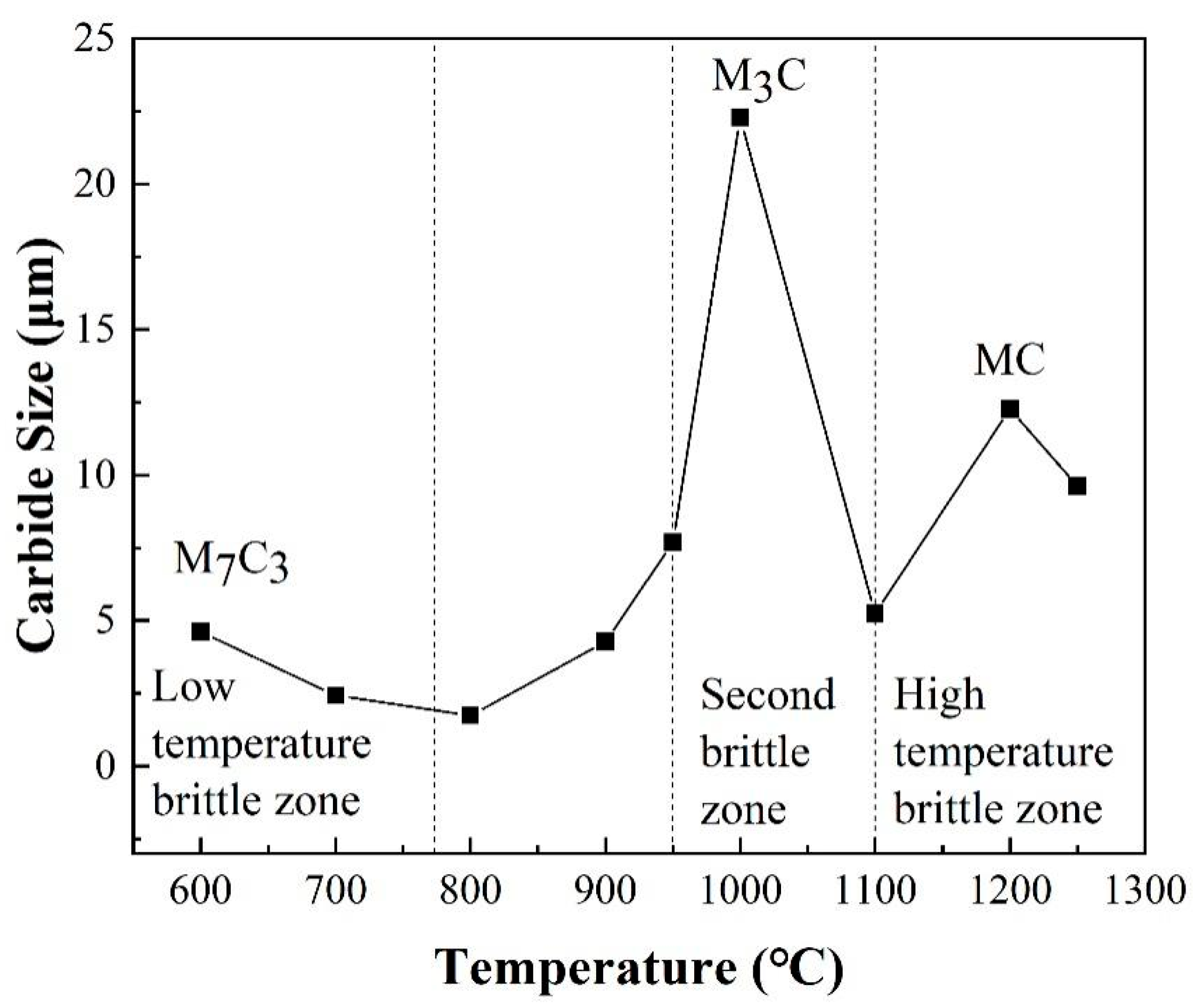
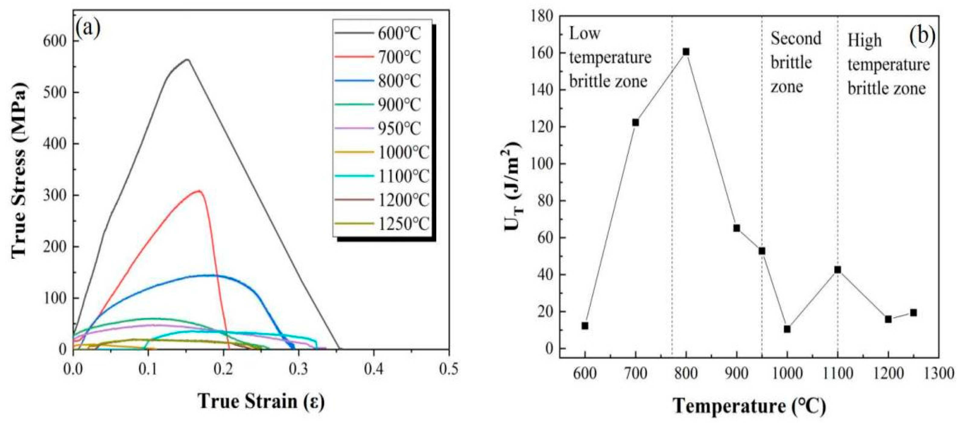
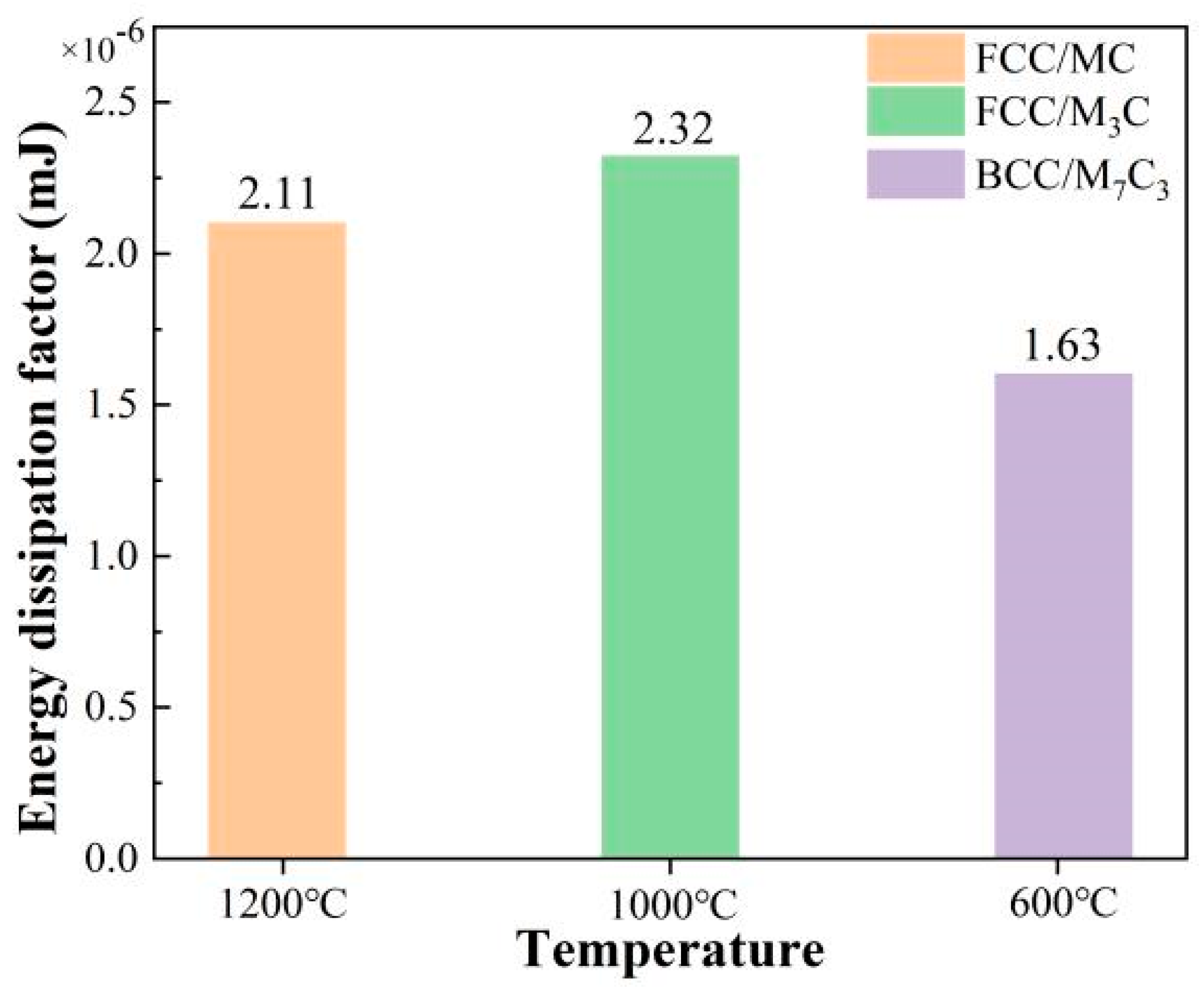
  • The high-temperature, second-temperature, and low-temperature brittleness zones of the high-carbon chromium-bearing steels were 1250 °C–1100 °C, 1100 °C–950 °C, and 800 °C–600 °C, respectively. The temperatures corresponding to high crack sensitivities within the brittleness range were 1200, 1000, and 600 °C. The cracking sensitivity of carbides to high-carbon chromium-bearing steel casting zones follows the order of strong to weak: M3C > MC > M7C3.
  • Mixed-crystal fracture occurred in the high-temperature brittle zone, and the critical stress and strain for the initiation of cracks at the matrix/MC interface were 13.85 MPa and 8.21 × 10⁻³, respectively. The main reason for the formation of mixed-crystal fractures was that the hardness of the stripe MC carbide (Fe0.875Cr0.125C) was greater than that of the matrix, and the stress concentration at the carbide tip was greater.
  • Brittle fracture was the fracture mode in the second brittle zone, with the critical stress and critical strain for the initiation of cracks at the matrix/M3C interface being 4.64 MPa and 6.52 × 10⁻³, respectively. The main reason for the formation of brittle fractures was the large and easily enriched M3C carbide, which caused cracks to initiate at the interface of the matrix/carbide and extend rapidly.
  • Intergranular fracture was a fracture mode in the low-temperature brittle zone, and the critical stress and critical strain for the initiation of interface cracks in the matrix/M7C3 were 17.86 MPa and 1.86 × 10⁻², respectively. The main reason for the formation of intergranular fractures was that the strength of the grain boundaries at the trigeminal grain boundaries was reduced by the M7C3 carbide, resulting in the formation of dimple-shaped nuclear particles during the stretching process.

Author Contributions

Conceptualization, Q.F. and Y.Z.; methodology, Q.F.; software, Y.W. (Yajun Wang) and G.T.; validation, J.L., Y.W. (Yajun Wang) and Y.W. (Yitong Wang); formal analysis, Y.Z. and G.T.; investigation, Y.W. (Yitong Wang); resources, J.L.; data curation, Q.F.; writing—original draft, Q.F.; writing—review and editing, Y.Z. and Y.W. (Yitong Wang); visualization, G.T.; supervision, J.L.; project administration, J.L.; funding acquisition, Y.Z., J.L. and Y.W. (Yitong Wang). All authors have read and agreed to the published version of the manuscript.

Funding

The authors wish to acknowledge the financial support from the National Natural Science Foundation of China (Nos. 52274333 and U21A20112), Distinguished Young Science Fund Project of Hebei Natural Science Foundation (E2023209128), Science and Technology Project of Hebei Education Department (ZD2019001, QN2022178), Science and Technology Plan Project of Tangshan (19140205F), Outstanding Youth Science Fund Project of Hebei Natural Science Foundation (E2022209019), Innovation Research Group Project of Natural Science Foundation of Hebei Province (E2022209093), Hebei Province Central Guidance Local Science and Technology Development Fund Project (236Z3803G), and Key Scientific Research Project of North China University of Science and Technology (ZD-ST-202311-23).

Data Availability Statement

The original contributions presented in the study are included in the article, further inquiries can be directed to the corresponding authors.

Conflicts of Interest

The authors declare that they have no known competing financial interests or personal relationships that could have appeared to influence the work reported in this paper.

References

  1. Loaiza, T.; Babu, R.P.; Ooi, S.; Hedström, P. Refining the mechanistic understanding of microstructural decay during rolling contact fatigue in 52100 bearing steel tempered at high temperature. J. Mater. Sci. 2023, 58, 17093–17112. [Google Scholar] [CrossRef]
  2. Sreeraj, K.; Maheshwari, H.K.; Rajagopal, P.; Ramkumar, P. Non-contact monitoring and evaluation of subsurface white etching area (WEA) formation in bearing steel using Rayleigh surface waves. Tribol. Int. 2021, 162, 107134. [Google Scholar] [CrossRef]
  3. Hu, R.; Hu, S.; Zhang, X.; Yang, M.; Zheng, N. Innovative simulation method of the spherical steel bearing applied to high-speed railway bridges. Struct. Eng. Mech. 2023, 85, 265–274. [Google Scholar]
  4. Lorenz, S.J.; Sadeghi, F.; Trivedi, H.K.; Kirsch, M.S. Investigation into rolling contact fatigue performance of aerospace bearing steels. Int. J. Fatigue 2023, 172, 107646. [Google Scholar] [CrossRef]
  5. Yue, X.; Hu, S.; Wang, X.; Liu, Y.; Yin, F.; Hua, L. Understanding the nanostructure evolution and the mechanical strengthening of the M50 bearing steel during ultrasonic shot peening. Mater. Sci. Eng. A 2022, 836, 142721. [Google Scholar] [CrossRef]
  6. Zeng, T.Y.; Li, W.; Wang, N.M.; Wang, W.; Yang, K. Microstructural evolution during tempering and intrinsic strengthening mechanisms in a low carbon martensitic stainless bearing steel. Mater. Sci. Eng. A 2022, 836, 142736. [Google Scholar] [CrossRef]
  7. Shao, Z.; Zhu, Y.; Zhang, P.; Cao, Y.; Wang, B.; Xu, Z.; Liu, H.; Gu, X.; Liu, H.; Li, D.; et al. Effect of primary carbides on rolling contact fatigue behaviors of M50 bearing steel. Int. J. Fatigue 2024, 179, 108054. [Google Scholar] [CrossRef]
  8. Sharma, T.; Bonagani, S.K.; Kumar, N.N.; Harish, D.; Krishna, K.M.; Samajdar, I.; Kain, V. Effect of thermal aging on embrittlement of Cr–Mo–V pressure vessel steel. J. Nucl. Mater. 2019, 527, 151817. [Google Scholar] [CrossRef]
  9. Lee, S.; Kim, S.; Hwang, B.; Lee, B.S.; Lee, C.G. Effect of carbide distribution on the fracture toughness in the transition temperature region of an SA 508 steel. Acta Mater. 2002, 50, 4755–4762. [Google Scholar] [CrossRef]
  10. Wang, H.; Li, J.; Zhang, C.; Wang, W.; Liu, Y. Effects of niobium on network carbide in high-carbon chromium bearing steel by in situ observation analysis. Ironmak. Steelmak. 2021, 48, 155–160. [Google Scholar] [CrossRef]
  11. Erişir, E.; Ararat, Ö.; Bilir, O.G. Enhancing Wear Resistance of 100Cr6 Bearing Steels by New Heat Treatment Method. Metall. Mater. Trans. A 2022, 53, 850–860. [Google Scholar] [CrossRef]
  12. Li, Y.; Jiang, Z.; Wang, P.; Li, D.; Li, Y. Effect of a modified quenching on impact toughness of 52100 bearing steels. J. Mater. Sci. Technol. 2023, 160, 96–108. [Google Scholar] [CrossRef]
  13. Zhou, G.; Wei, W.; Liu, Q. Effect of Hot Rolling on Microstructural Evolution and Wear Behaviors of G20CrNi2MoA Bearing Steel. Metals 2021, 11, 957. [Google Scholar] [CrossRef]
  14. Su, Y.; Yang, S.; Yu, X.F.; Zhou, C.B.; Liu, Y.B.; Feng, X.C.; Zhao, Q.; Wu, J.D. Effect of Austempering Temperature on Microstructure and Mechanical Properties of M50 Bearing Steel. J. Mater. Res. Technol. 2022, 20, 4576–4584. [Google Scholar] [CrossRef]
  15. Du, N.; Liu, H.; Cao, Y.; Fu, P.; Sun, C.; Liu, H.; Li, D. Formation mechanism of MC and M2C primary carbides in as-cast M50 bearing steel. Mater. Charact. 2021, 174, 111011. [Google Scholar] [CrossRef]
  16. Louhenkilpi, S. Continuous casting of steel. In Treatise on Process Metallurgy; Elsevier: Amsterdam, The Netherlands, 2014; pp. 373–434. [Google Scholar]
  17. Fredriksson, H.; Akerlind, U. Materials Processing during Casting; Wiley: Chichester, UK, 2006. [Google Scholar]
  18. Sun, H.; Li, L. Application of swirling flow nozzle and investigation of superheat dissipation casting for bloom continuous casing. Ironmak. Steelmak. 2016, 43, 228–233. [Google Scholar] [CrossRef]
  19. Yang, B.; Zhang, H.; Wang, M. Modelling of continuous casting processes parameters on the shrinkage cavity formation in bearing steel blooms. Ironmak. Steelmak. 2023, 50, 1169–1180. [Google Scholar] [CrossRef]
  20. Sun, H.; Li, L.; Cheng, X.; Qiu, W.; Liu, Z.; Zeng, L. Reduction in macrosegregation on 380 mm×490 mm bloom caster equipped combination M+F-EMS by optimising casting speed. Ironmak. Steelmak. 2015, 42, 439–449. [Google Scholar] [CrossRef]
  21. Liu, H.; Xu, M.; Qiu, S.; Zhang, H. Numerical simulation of fluid flow in a round bloom mold with in-mold rotary electromagnetic stirring. Metall. Mater. Trans. B 2012, 43, 1657–1675. [Google Scholar] [CrossRef]
  22. Ren, B.Z.; Chen, D.F.; Wang, H.D.; Long, M.J.; Han, Z.W. Numerical simulation of fluid flow and solidification in bloom continuous casting mould with electromagnetic stirring. Ironmak. Steelmak. 2015, 42, 401–408. [Google Scholar] [CrossRef]
  23. Domitner, J.; Wu, M.; Kharicha, A.; Ludwig, A.; Kaufmann, B.; Reiter, J.; Schaden, T. Modeling the effects of strand surface bulging and mechanical softreduction on the macrosegregation formation in steel continuous casting. Metall. Mater. Trans. A 2014, 45, 1415–1434. [Google Scholar] [CrossRef]
  24. Zong, N.; Huang, J.; Liu, Y.; Jing, T.; Lu, Z. Controlling centre segregation and shrinkage cavities without internal crack in as-cast bloom of steel GCr15 induced by soft reduction technologies. Ironmak. Steelmak. 2021, 48, 944–952. [Google Scholar] [CrossRef]
  25. Sun, H.; Li, L.; Wang, J.; Cheng, X.; Zhou, F. Coordinating optimisation of F-EMS and soft reduction during bloom continuous casting process for special steel. Ironmak. Steelmak. 2018, 45, 708–713. [Google Scholar] [CrossRef]
  26. Jiang, D.Q.; Wang, R.; Zhang, Q.; Zhang, Z.Q.; Tu, T.S.; Wang, J.; Ren, Z.M. Effect of final electromagnetic stirring on solidification microstructure of GCr15 bearing steel in simulated continuous casting. J. Iron Steel Res. Int. 2020, 27, 141–147. [Google Scholar] [CrossRef]
  27. An, H.; Bao, Y.; Wang, M.; Yang, Q.; Huang, Y. Improvement of centre segregation in continuous casting bloom and the resulting carbide homogeneity in bearing steel GCr15. Ironmak. Steelmak. 2019, 46, 896–905. [Google Scholar] [CrossRef]
  28. Peng, Z.; Mei, T.; Zheng, J.; Yuan, Y.; Wang, L. Cracking Behavior and High-Temperature Thermoplastic Analysis of 09CrCuSb Steel Billets. Metals 2023, 13, 1058. [Google Scholar] [CrossRef]
  29. Zhou, W.; Liu, L.; Li, B.; Wu, P.; Song, Q. Structural, elastic and electronic properties of intermetallics in the Pt–Sn system: A density functional investigation. Comput. Mater. Sci. 2009, 46, 921–931. [Google Scholar] [CrossRef]
  30. Li, Q.; Qiu, N.; Liu, Z.; Huang, Q.; An, P.; Du, S. Structural, electronic, elastic and thermal properties of Cr-doped U3Si2: A DFT study. J. Nucl. Mater. 2023, 579, 154388. [Google Scholar] [CrossRef]
  31. Fojt-Dymara, G.; Opiela, M.; Borek, W. Susceptibility of high-manganese steel to high-temperature cracking. Materials 2022, 15, 8198. [Google Scholar] [CrossRef]
  32. Zeng, Y.N.; Feng, Q.; Li, J.G.; Wang, Y.J.; Tang, G.Z. Effect of the microstructure on the crack initiation during thermal cycling of Nb–Ti-bearing continuous casting slabs. Ironmak. Steelmak. 2021, 48, 370–378. [Google Scholar] [CrossRef]
  33. Barbier, D.; Guérin, J.D.; Dubar, M.; Bénard, T.; Bonneau, S.; Cabrera, E.S.P. Hot ductility and flow stress of AISI 4130 and 52100-type steels. Mater. Sci. Eng. A 2017, 690, 37–43. [Google Scholar] [CrossRef]
  34. Huitron, R.M.P.; Lopez, P.E.R.; Vuorinen, E.; Jentner, R.; Kärkkäinen, M.E. Converging criteria to characterize crack susceptibility in a micro-alloyed steel during continuous casting. Mater. Sci. Eng. A 2020, 772, 138691. [Google Scholar] [CrossRef]
  35. Das, A.; Tarafder, S. Experimental investigation on martensitic transformation and fracture morphologies of austenitic stainless steel. Int. J. Plast. 2009, 25, 2222–2247. [Google Scholar] [CrossRef]
  36. Chen, K.; Jiang, Z.; Liu, F.; Yu, J.; Li, Y.; Gong, W.; Chen, C. Effect of quenching and tempering temperature on microstructure and tensile properties of microalloyed ultra-high strength suspension spring steel. Mater. Sci. Eng. A 2019, 766, 138272. [Google Scholar] [CrossRef]
  37. Li, H.; Zhang, H.; Lv, Z.F.; Zhu, Z.F. Cementite Dissolution Kinetics of High Carbon Chromium Steel During Intercritical Austenitization. J. Phase Equilibria Diffus. 2017, 38, 543–551. [Google Scholar] [CrossRef]
  38. Du, G.; Li, J.; Wang, Z.B. Control of carbide precipitation during electroslag remelting-continuous rapid solidification of GCr15 steel. Metall. Mater. Trans. B 2017, 48, 2873–2890. [Google Scholar] [CrossRef]
  39. Wang, F.; Qian, D.S.; Xiao, P.; Deng, S. Accelerating cementite precipitation during the non-isothermal process by applying tensile stress in GCr15 bearing steel. Materials 2018, 11, 2403. [Google Scholar] [CrossRef]
  40. Florio, B.J.; Fawell, P.D.; Small, M. The use of the perimeter-area method to calculate the fractal dimension of aggregates. Powder Technol. 2019, 343, 551–559. [Google Scholar] [CrossRef]
  41. Jiang, D.; Zhang, L. Influence of Cooling Parameters on the Microstructure and Primary Carbide Precipitation in GCr15 Steel. Steel Res. Int. 2021, 92, 2100208. [Google Scholar] [CrossRef]
  42. Tanaka, K.; Mori, T.; Nakamura, T. Cavity formation at the interface of a spherical inclusion in a plastically deformed matrix. Philos. Mag. A J. Theor. Exp. Appl. Phys. 1970, 21, 267–279. [Google Scholar] [CrossRef]
  43. Kawakami, H.; Tamaki, K.; Suzuki, J.; Takahashi, K.; Imae, Y.; Ogusu, S. Effect of Coarse Carbide Particle on SR embrittlement in the HAZ of 21/4Cr-1Mo steel. Weld. World 2011, 55, 78–85. [Google Scholar] [CrossRef]
  44. Mori, T.; Tanaka, K. Average stress in matrix and average elastic energy of materials with misfitting inclusions. Acta Metall. 1973, 21, 571–574. [Google Scholar] [CrossRef]
  45. Li, X.B.; Ding, H.; Tang, Z.Y.; He, J.C. Formation of internal cracks during soft reduction in rectangular bloom continuous casting. Int. J. Miner. Metall. Mater. 2012, 19, 21–29. [Google Scholar] [CrossRef]
  46. Li, G.; Ji, C.; Zhu, M. Prediction of internal crack initiation in continuously cast blooms. Metall. Mater. Trans. B 2021, 52, 1164–1178. [Google Scholar] [CrossRef]
  47. Cai, W.; Sun, C.; Wang, C.; Qian, L.; Li, Y.; Fu, M.W. Modelling of the intergranular fracture of TWIP steels working at high temperature by using CZM–CPFE method. Int. J. Plast. 2022, 156, 103366. [Google Scholar] [CrossRef]
  48. Zhao, Q.; Wahab, M.A.; Ling, Y.; Liu, Z. Fatigue crack propagation within Al-Cu-Mg single crystals based on crystal plasticity and XFEM combined with cohesive zone model. Mater. Des. 2021, 210, 110015. [Google Scholar] [CrossRef]
  49. Wang, W.Z.; Hong, H.U.; Kim, I.S.; Choi, B.G.; Jeong, H.W.; Kim, M.Y.; Jo, C.Y. Influence of γ′ and grain boundary carbide on tensile fracture behaviors of Nimonic 263. Mater. Sci. Eng. A 2009, 523, 242–245. [Google Scholar] [CrossRef]
  50. Min, J.H.; Heo, Y.U.; Kwon, S.H.; Moon, S.W.; Kim, D.G.; Lee, J.S.; Yim, C.H. Embrittlement mechanism in a low-carbon steel at intermediate temperature. Mater. Charact. 2019, 149, 34–40. [Google Scholar] [CrossRef]
Figure 1. Experimental plan for high-temperature tensile testing of GCr15 bearing steel.
Metals 14 00335 g001
Figure 2. Crack sensitivity analysis in high-temperature casting of bearing steel. (a) Reduction in area and ultimate tensile strength and (b) true fracture strength and true fracture ductility.
Metals 14 00335 g002
Figure 3. SEM micrographs observed on tensile fracture morphology. ((A1A3): 1200 °C, (B1B3): 1000 °C, (C1C3): 600 °C, (A1,B1,C1): fracture surface after tension, (A2,B2,C2): side view of sample after fracture, and (A3,B3,C3): enlarged observation of (A2,B2,C2)).
Metals 14 00335 g003
Figure 4. XRD analysis results of high-carbon chromium-bearing steel at different temperatures.
Metals 14 00335 g004
Figure 5. Carbide microstructure and energy spectrum analysis results. (a) Network carbide MC, (b) M3C carbide, and (c) M7C3 carbide.
Metals 14 00335 g005
Figure 6. Thermo-Calc calculation results. (a) Solidification process and (b) equilibrium phase diagram (1600 °C~200 °C).
Metals 14 00335 g006
Figure 7. Equivalent diameter of carbides in different brittle regions.
Metals 14 00335 g007
Figure 8. True stress–strain curves and total strain tensile energy of casting under brittle zones. (a) True stress–strain curves (1250 °C~600 °C, 0.001 s−1) and (b) calculation results of strain total energy.
Metals 14 00335 g008
Figure 9. Diameter dependency of plastic strain for decohesion at carbide/matrix boundary. (The dashed line represents the critical stress for crack initiation in GCr15 bearing steel castings in the secondary cooling and straightening stages [45,46]).
Metals 14 00335 g009
Figure 10. Simulation of process simulation of austenite/MC carbide interface fracture for ABAQUS. (a) Initialed of stretching, (b) Continuoued of stretching, (c) Initialed of crack, (d) Expended of crack, (e) Final state of crack expended and (f) Sreess-strain curve during fracture process.
Metals 14 00335 g010
Figure 11. Simulation of process simulation of austenite/M3C carbide interface fracture for ABAQUS. (a) Initialed of stretching, (b) Continuoued of stretching, (c) Initialed of crack, (d) Expended of crack, (e) Final state of crack expended and (f) Sreess-strain curve during fracture process.
Metals 14 00335 g011
Figure 12. Simulation of process simulation of austenite/M7C3 carbide interface fracture for ABAQUS. (a) Initialed of stretching, (b) Continuoued of stretching, (c) Initialed of crack, (d) Expended of crack, (e) Final state of crack expended and (f) Sreess-strain curve during fracture process.
Metals 14 00335 g012
Figure 13. Energy dissipation factor of matrix/carbide model during stretching process.
Metals 14 00335 g013
Table 1. Chemical composition of GCr15 steel grades (mass percentage, %).
ElementsCSiMnPSCrFe
Wt.%0.970.210.320.0170.0011.4996.992
Table 2. Lattice constants (Å) and elastic matrix parameters (Cij) after relaxation of different phase.
PhaseSpace GroupLattice Constants (Å)Elastic Matrix Parameters (Cij) (GPa)
FCC-FeFm 3 ¯ ma = b = c = 2.362C11 = 87.9 C12 = 399.1 C44 = 200.7
BCC-FeFm 3 ¯ ma = b = c = 2.866C11 = 84.3 C12 = 397.1 C44 = 198.3
MCFm 3 ¯ ma = b = c = 2.357C11 = 603.3 C12 = 213.4 C44 = 46.5
M3CPnmaa = 4.858 b = 6.554 c = 4.341C11 = 372.5 C22 = 422.7 C33 = 427.2
C12 = 145.9 C13 = 178.4 C23 = 211.1
C44 = 50.4 C55 = 52.0 C66 = 99.9
M7C3P63mca = b = 5.961 c = 6.939C11 = 371.6 C33 = 335.1 C44 = 93.7
C12 = 186.9 C13 = 175.7 C66 = 90.6
Table 3. Bulk modulus (B), shear modulus (G), ratios of B/G, Young’s modulus (E), and Poisson’s ratio (v) of different phases (GPa).
PhaseB (GPa)G (GPa)E (GPa)B/Gv
FCC-Fe295.4 57.6 217.2 5.090.408
BCC-Fe292.83 56.4 159.05 5.1890.409
MC343.39 105.9 272.8 3.240.720
M3C255.9 86.26 193.4 2.950.348
M7C3238.091.6243.62.590.329
Disclaimer/Publisher’s Note: The statements, opinions and data contained in all publications are solely those of the individual author(s) and contributor(s) and not of MDPI and/or the editor(s). MDPI and/or the editor(s) disclaim responsibility for any injury to people or property resulting from any ideas, methods, instructions or products referred to in the content.

