Article

Carbon Nano-Onions as Nanofillers for Enhancing the Damping Capacity of Titanium and Fiber-Reinforced Titanium: A Numerical Investigation

by
Georgios I. Giannopoulos
* and
Nikolaos D. Batsoulas
Mechanics and Materials Laboratory, Department of Mechanical Engineering, School of Engineering, University of the Peloponnese, 26334 Patras, Greece
*
Author to whom correspondence should be addressed.
Metals 2023, 13(9), 1577; https://doi.org/10.3390/met13091577
Submission received: 9 August 2023 / Revised: 5 September 2023 / Accepted: 7 September 2023 / Published: 9 September 2023
(This article belongs to the Special Issue Metal Matrix Composites Reinforced with Carbon Nanomaterials)

Abstract

:
Improving the damping capacity of metal matrix composites is crucial, especially for applications in the aerospace industry where reliable performance against vibrations and shocks is mandatory. The main objective of the present study is the numerical prediction of the damping behavior of alpha titanium matrix nanocomposites reinforced with hollow carbon nano-onions at various volume fractions. According to the proposed numerical scheme, a structural transient analysis is implemented using the implicit finite element method (FEM). The metal matrix nanocomposites are modeled via the utilization of appropriate representative volume elements. To estimate the mechanical and damping behavior of the nanocomposite representative volume elements, axial sinusoidally time-varying loads are applied to them. The damping capacity of the metal matrix nanocomposites is then estimated by the arisen loss factor, or equivalently the tan delta, which is computed by the time delay between the input stress and output strain. The analysis shows that the loss factor of alpha titanium may be improved up to 60% at 100 Hz by adding 5 wt% carbon nano-onions. The numerical outcome regarding the dynamic properties of the carbon nano-onions/alpha titanium nanocomposites is used in a second-level analysis to numerically predict their damping performance when they are additionally reinforced with unidirectional carbon fibers, using corresponding representative volume elements and time-varying loadings along the effective direction. Good agreement between the proposed computational and other experimental predictions are observed regarding the stiffness behavior of the investigated metal matrix nanocomposites with respect to the mass fraction of the carbon-onion nanofillers in the titanium matrix.

1. Introduction

Nearly every industrial field has been significantly impacted by nanotechnology and its discoveries. The industry of metal matrix composites (MMCs) is not an exception. Recently, a significant amount of research effort has been undertaken in the field of MMCs to adopt the advantages offered by carbon nanomaterials [1]. With their distinctive electrical, mechanical, and thermal characteristics, carbon nanotubes and graphene nanosheets are desirable reinforcement materials for making lightweight, highly durable, and high-performing MMCs for applications in functional and structural engineering [1,2]. Due to their extraordinary properties, carbon nanomaterials [1] as well as other nanoparticles such as boron nitride nanotubes, boron nitride nanosheets, MXene, and metal dichalcogenides [2] have become useful nanoscale fillers for creating metal matrix nanocomposites (MMNCs), which are being used to circumvent the performance restrictions of conventional MMCs. However, MMNCs, which utilize fullerenes as reinforcement, are less well recognized, despite the fact that these spherical nanomaterials share analogous structural and physical characteristics with graphene. Fullerenes are hollow molecular structures that are made of hexagonal and pentagonal carbon rings [3]. A fullerene may be imagined as a single-layer graphene sheet, folded into a spherical shape. Similarly, the wrapping of multilayer graphene sheets, i.e., monocrystal graphite sheets, into spherical shapes leads to a new family of carbon nanomaterials named carbon nano-onions (CNOs) [4]. These carbon nanoparticles due to their hollow spherical molecular structure may become intriguing substitutes for single-walled carbon nanotubes (CNTs) and graphene since they are more plentiful in a purified state and considerably more affordable. Additionally, single-layer and multilayer fullerenes may provide a high level of purity and keep their quality even after several reproduction cycles. Moreover, due to their shape, they may be easily dispersed into a metallic matrix without being damaged due to severe mechanical processes [5].
Due to the unique structural and chemical characteristics of CNOs, research in the relevant domain is continuously increasing. Mykhailiv et al. [4] presented a very interesting review of all the freshly established knowledge concerning CNOs. They evaluated the most relevant literature reports regarding the fabrication methods, the remarkable physical and chemical properties, and the possible applications of these fascinating carbon allotropes. Regarding the potential innovative applications of CNOs, Zeiger et al. [6] discussed the use of multiple concentric fullerene-like carbon shells as electrode materials for supercapacitors plus as conductive additives and for redox-active species. On the other hand, significant experimental effort was made to establish reliable processes for manufacturing CNOs. In a notable attempt, He et al. [7] provided a practical method to produce CNOs on a large scale over a Ni/Al catalyst by chemical vapor deposition (CVD) with diameters ranging from 5 to 50 nm. More recently, Klose et al. [8] established a simple synthesis approach for obtaining structured hollow CNOs with hierarchical porosities from the metal–organic framework Basolite F300, made up of several graphitic shells forming a hierarchical micro- and mesoporous carbon material. Based on a fast CVD technique at 700 °C with magnesium oxide-supported cobalt as a catalyst, Ruan et al. [9] managed to produce gram-scale hollow CNOs. They provided images from scanning electron microscopy (SEM) and transmission electron microscopy (TEM) showing that the produced nanomaterials were made up of hollow polyhedral particles with diameters ranging from 10 to 50 nm. On the other hand, Fan et al. [10] annealed nanodiamonds in a spark plasma sintering (SPS) furnace to synthesize onion-like carbon powder, which was used as reinforcement in a titanium (Ti) matrix at a mass fraction of 0.1 to 1.0%. Then, they measured the tensile properties of the arisen nanocomposites, observing significant improvements. Very recently, Aissou et al. [11] demonstrated a fast and efficient process for the synthesis of graphitic nanocapsules, i.e., onion-like carbon structures consisting of concentric polyhedral multilayer shells, with diameters between 70 and 300 nm. Performing thermal decomposition of methane using a plasma torch, they achieved a progressive evolution of the morphology from graphene nanoflakes to carbon nano-onions with increasing pressure or methane flow rate. In the field of theoretical modeling of the structural behavior of CNOs, little has been carried out. Characteristically, Bowan et al. [12] adopted the Lennard-Jones potential in conjunction with the continuum approximation to describe the interaction energy between adjacent shells for both spherical and spheroidal carbon onions, assuming structures of either concentric spherical or ellipsoidal fullerenes with n-layers. Using a similar theoretical technique, Todt et al. [13] simulated the growth of CNOs by utilizing continuum mechanical shell models. Using a molecular dynamic (MD)-based method, Izadi et al. [14] predicted the elastic properties of polymer nanocomposites reinforced with a C60@C240 carbon onion. Very recently, Pereira Júnior et al. [15] performed MD simulations based on the ReaxFF potential model to study the dynamical behavior and the structural transformations of CNOs under high-velocity impacts against rigid substrates.
In this work, given the above-mentioned observations, a finite element procedure is formulated with the main aim of approximating the damping behavior and other mechanical characteristics of titanium filled with CNOs. The idea lies in the fact that the characteristic multilayer hollow structure of CNOs could contribute to the enhancement of the damping of titanium and its alloys, which is a very important requirement for applications where vibrational and impact loadings are present [16,17,18,19]. The CNOs are practically spherical formations of multilayer graphene whose good damping capacity at a low-frequency regime has already been demonstrated [20]. In addition, it has been already proven that the existence of porosity and voids within a metallic material may lead to an increase in its damping capacity [21,22]. Thus, the addition of hollow CNOs in Ti is expected to additionally contribute to its energy dissipation ability in an indirect manner. Among various types of available Ti materials, a single-phase alpha-Ti (α-Ti) is chosen as a matrix material. Such titanium alloys are usually used in high-temperature applications such as in compressor discs and blades in aero-engines [23], which exhibit shock vibrations. Specifically, the material properties of the standardized α-Ti alloy VT0-1 are adopted [24,25], which has recently been used successfully in additive manufacturing [26]. The proposed finite element (FE) numerical scheme for the simulation of CNOs/α-Ti nanocomposites under dynamic mechanical loadings is realized by utilizing the ANSYS workbench [27,28]. ANSYS Workbench is a commercial platform used to execute numerous kinds of structural, thermal, and other analyses. The entire simulation process is tied together by a project schematic, permitting interaction with ANSYS applications that are developed using basically C and C++, including CAD programs, meshing modules, optimization algorithms, finite element method (FEM) solvers, and other computational tools. The use of FEM for simulating titanium-based nanocomposites provides the advantage of low cost and time requirements for estimating their damping properties, which would require substantial, long-term, and laborious experimental efforts to be measured. Nonetheless, it is worth noting that the adoption of continuum mechanics numerical methods may lead to the misrepresentation of some nanoscale phenomena that atomistic methods could incorporate with an enormous, however, computational cost. Small displacement theory is assumed while the interface between the CNOs and the α-Ti is considered to be strong with negligible sliding and consequent energy dissipation due to friction. Appropriate periodic two-phase RVEs are created and discretized using three-dimensional (3D) solid FEs for the modeling of the α-Ti filled with CNOs. The RVEs are simulated, using structural implicit transient analysis, under sinusoidally time-varying axial loads. The input stresses, the output strains, and the phase shift between them are used to compute the loss factor and other mechanical properties of the investigated nanocomposites. Long as well as short carbon fibers (CFs) are commonly used to reinforce matrices that are already filled with carbon nanomaterials [29]. On the other hand, in an effort to improve the functionality of 3D printing components [30,31], CFs are now largely used in addictive manufacturing processes, opening new technological paths [32]. Therefore, in the present work, the prediction of the damping capacity of the previously analyzed CNOs/α-Ti nanocomposites which are extra reinforced with carbon fibers (CFs) [33,34,35,36,37], is also numerically estimated. It is found that the damping capacity enhancement of the investigated material systems due to the addition of the hollow carbon nanoparticles originates from the higher internal friction of the multilayer graphene-like walls of the CNOs as well as the arisen porosity. The present computational results regarding the elastic stiffness of the tested CNOs/α-Ti nanocomposites are compared with analogous experimental ones where possible. In the present work, for the first time, the damping behavior of a titanium matrix nanocomposite is explored via an FEM-based computational scheme. Moreover, the evaluation of damping enhancement accomplished by the addition of CNOs in a metal matrix, as well as the mechanisms behind such a phenomenon, which is the main target we aimed to achieve here via FEM simulations, has not been presented elsewhere.
The rest of the paper is organized as follows: Section 2 refers to the FE modeling of the investigated nanocomposites and their constituents. The specific section also presents the adopted computational scheme and formulations for the calculation of the dynamic properties of the MMNCs. The numerical results concerning the mechanical and damping performance of the proposed MMNCs are demonstrated in Section 3, while the conclusions and directions for future work are pointed out in Section 4.

2. Materials and Methods

2.1. Numerical Treatment of Basic Phases

2.1.1. Alphα Titanium Alloy

A single-phase titanium alloy that is commercially known as VT0-1 was used as the basic matrix phase. Practically, it is an α-Ti commercial alloy that contains, by weight, up to 0.18% Fe, up to 0.07% C, up to 0.04% N, up to 0.1% Si, up to 0.12% O, up to 0.004 H%, and 0.3% other impurities [25]. The microstructure of the specific commercial metal is characterized by crystal grains, which are formed by α-Ti phase [25]. The α-Ti matrix is assumed to act as an isotropic continuum medium having the typical mechanical properties indicated in Table 1 [24]. Considering the requirements of the present study, a crucial aspect is the proper representation energy dissipation capability of the adopted α-Ti matrix. Therefore, the damping behavior of the specific material is defined on the basis of the well-known loss factor. The “loss factor” is a dimensionless coefficient characterizing how oscillations in a system diminish after being under a disturbance. It is equivalent to the “loss tangent” or “internal friction” and is usually represented by the symbol tanδ. It should also be noted that the damping ratio ζ of a material or system is equal to half of the loss factor, i.e., ζ = tanδ/2. The loss factor of the α-Ti was chosen in accordance with some very recent experimental measurements obtained for the specific Ti phase, by applying micro-harmonic vibrations close to the room temperature and at a frequency of f = 100 Hz [19].

2.1.2. Carbon Nano-Onions

The CNOs, which were used to achieve the primary reinforcement of the α-Ti, were treated as continuum isotopic nanoparticles. Each CNO was computationally represented by utilizing a 3D hollow nanosphere of an external diameter d and a wall thickness t, as Figure 1a illustrates. The wall thickness t corresponds to the total thickness of the multilayer graphene shell along the radial direction governed by the van der Waals (vdW) interlayer interactions. Moreover, for a more realistic representation of the hollow CNOs and in order to follow typical experimental observations, their diameter d was assumed to follow a uniform variation in the range [10 nm, 50 nm] [9], while their thickness was taken equal to t = 3.4 nm, which, by considering the typical graphitic interlayer distance of 0.34 nm, corresponds to the thickness of a 10-layer graphene sheet. In addition, it was considered that the mechanical behavior of the CNOs was governed by typical elastic properties of curved multilayer graphene-based nanostructures [13]. According to a noticeable experimental study by Lahiri et al. [20], the loss factor of a 10-layer graphene nanomembrane at a vibrating frequency of 100 Hz was measured around tanδ = 0.518. This representative value was selected here for modeling the damping behavior of the CNOs wall. Table 1 provides a summary of the physical and mechanical properties used for the hollow multilayer graphene spheres. The geometry of each CNO was discretized by using 3D quadratic solid Fes, as shown in Figure 1b.

2.1.3. Carbon Fibers

In the second stage of the FEM simulation, it was assumed that the CNOs/α-Ti was additionally reinforced by continuous and almost unidirectionally oriented T300 CFs having a diameter D of 7 μm. The specific polyacrylonitrile-based CFs were used to reinforce a matrix material made of α-Ti, which was uniformly filled with the above-described CNOs at a variety of volume fractions. The density and the material properties used for modeling the T300 fibers [38] are mentioned in Table 1. Note that orthotropic elastic constants were applied to the fibers, with respect to their local coordinate system (χ, ψ, ζ) depicted in Figure 2a. Based on extensive experimental observations, reported by Lesieutre et al. [39] regarding the damping capacity of a single polyacrylonitrile-based fiber for frequencies above 80 Hz, it was assumed that the loss factor of each CF was represented by an average value of about 0.000159. A typical 3D FE mesh model of an individual T300 CF may be observed in Figure 2b.

2.2. Numerical Treatment of α-Ti Filled with CNOs

First, it was assumed that the CNOs were randomly distributed in the α-Ti nanocomposite. The volume fraction Vf of the CNO nanofillers in the α-Ti matrix was defined by:
V f = V CNO V CNO + V α Ti
where VCNO and Vα-Ti are the total volumes of the CNO nanofillers and the α-Ti matrix, respectively.
The investigation was performed for various volume fractions up to 25%. The α-Ti was used as a matrix, while pristine CNOs with dimensions of d = [10 nm, 50 nm] and t = 3.4 nm were placed randomly as nanofillers in cubic RVEs with a side length of l. The overall mechanical behavior of the nanocomposite RVEs remained essentially isotropic due to the random dispersion of the nanofillers. As shown in Figure 3a,c, the problem domain was specified in a global Cartesian coordinate system (x, y, z). To create proper FE models like illustrated in Figure 3b,d, the adaptive mesh option was adopted, while large deflection effects were neglected [27,28]. A small sinusoidally time-varying axial normal stress of the type σ = σ0sin(2πft), where f is the frequency set to 100 Hz and t is the time, was applied to the front vertical plane x = l of the RVE. An appropriate frictionless support condition was applied to the behind boundary x = 0 of the RVE. To ensure that the periodic symmetry of the RVE was satisfied (zero shear stresses should appear on these surfaces at all times), the vertical planes y = 0, y = l, z = 0, and z = l were restricted to remain parallel to their original shape. Transient structural analysis was used to simulate the modeled MMNCs until the time instant t = 1.1T was reached, where T = 1/f = 0.01 s is the period of the external load.

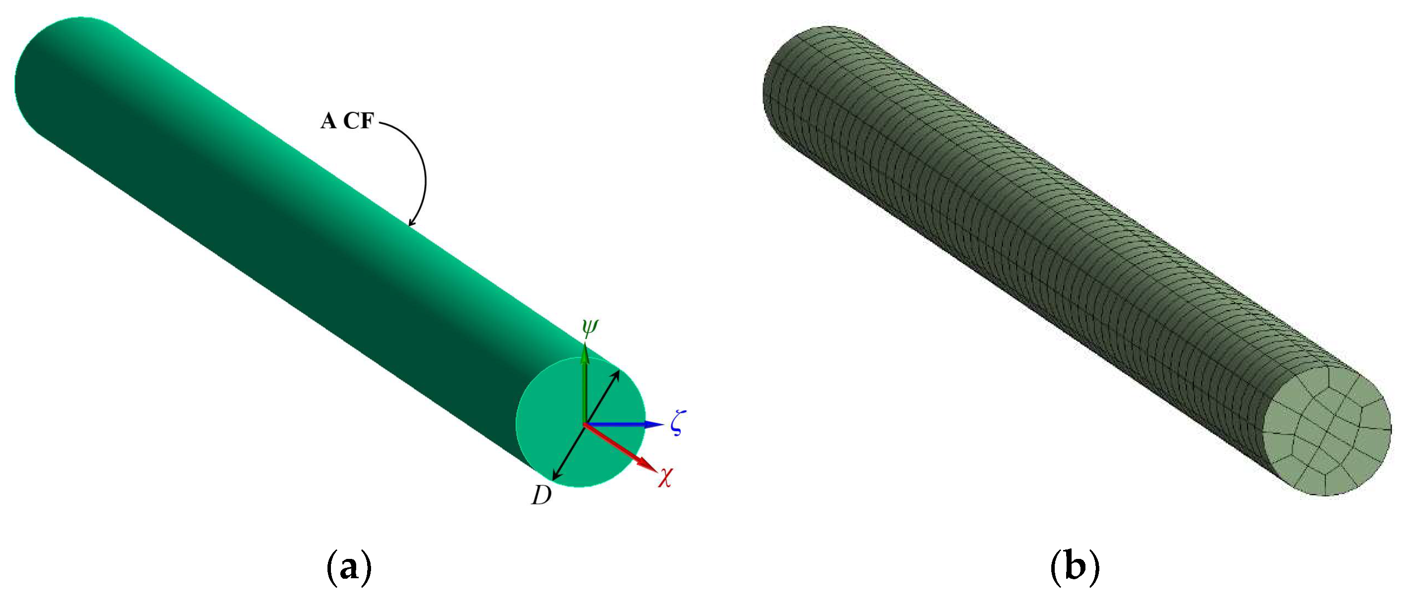
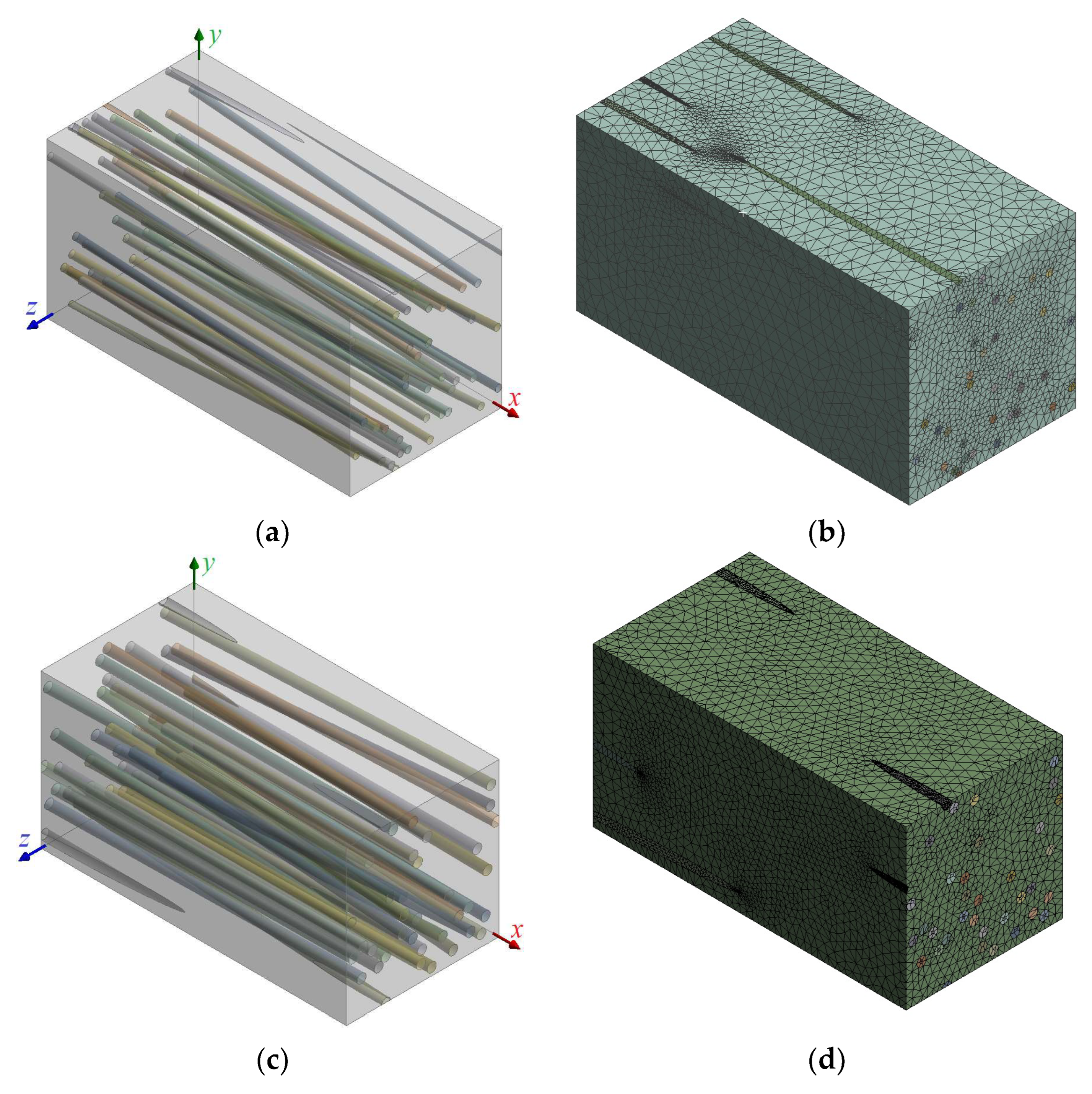
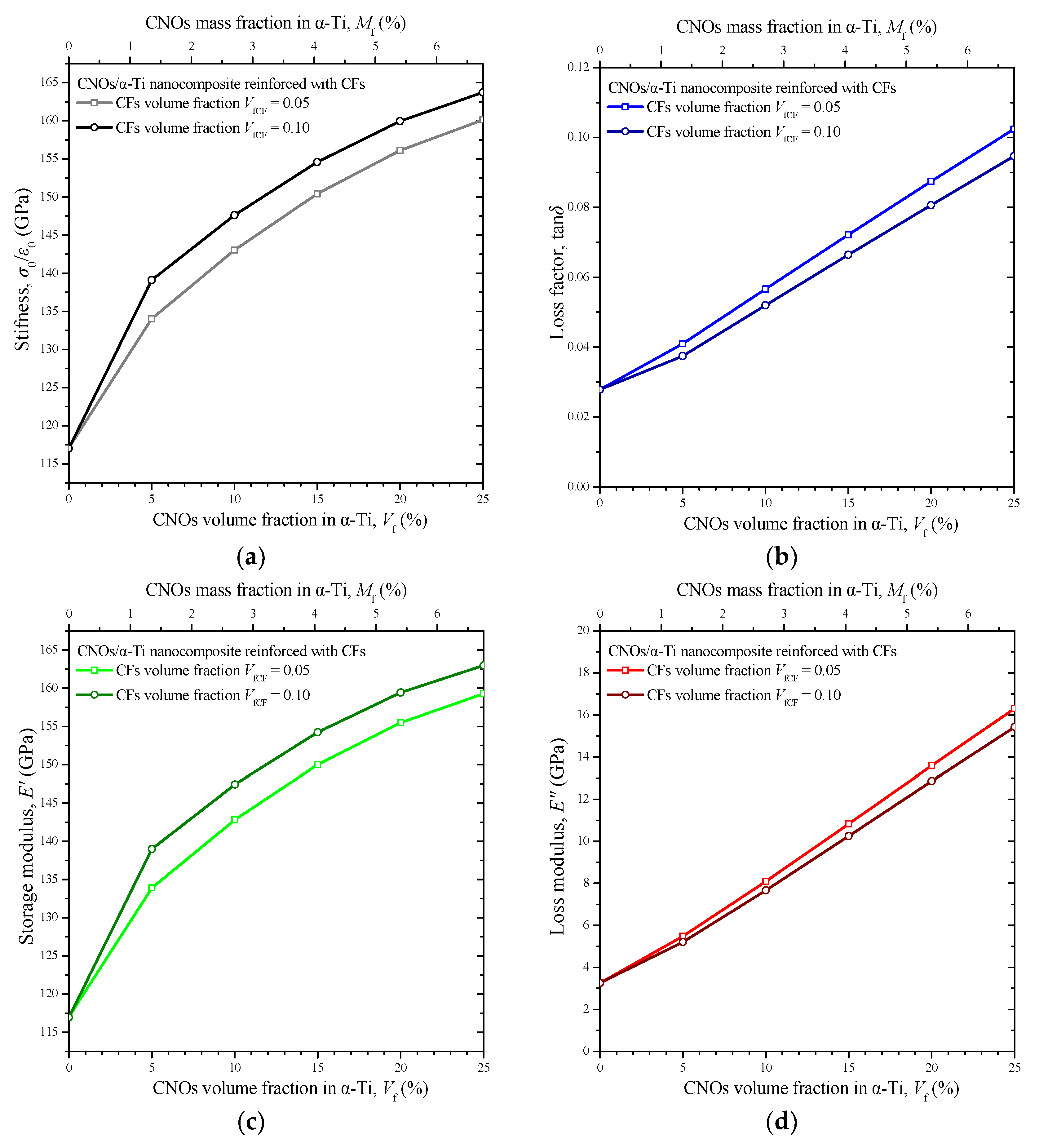
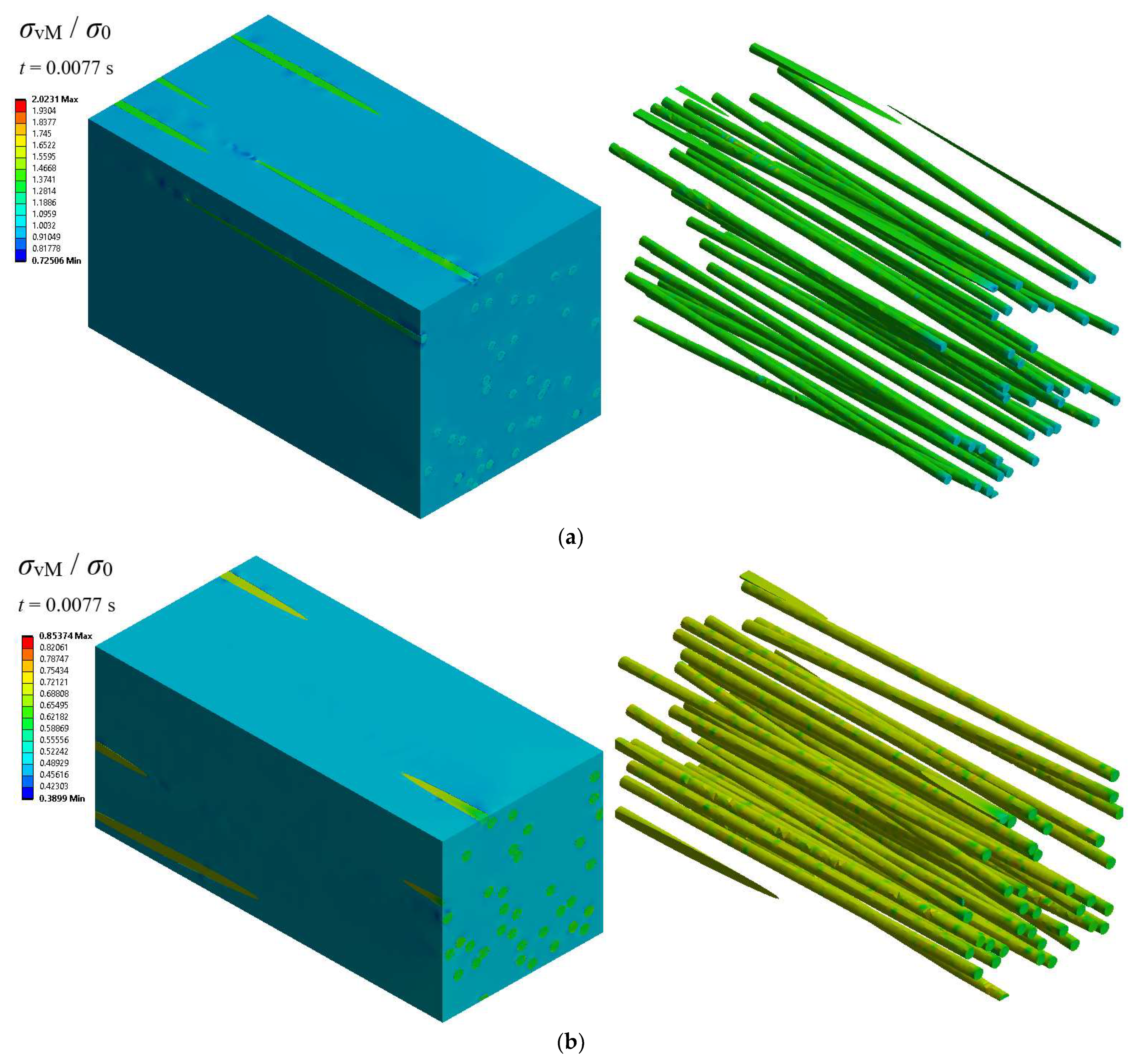
2.3. Numerical Treatment of CNOs/α-Ti Nanocomposite Reinforced with CFs

Having computed the dynamic material properties of the CNOs/α-Ti nanocomposites, the second stage of the present FEM-based study could be realized. At this second stage, the damping characterization of triple-phase materials composed of α-Ti, CNOs, and T300 CFs was achieved by introducing new RVEs. The investigated material system was composed of a matrix made of CNOs/α-Ti nanocomposite at various volume fractions and reinforcements of continuous and almost unidirectionally aligned T300 fibers, having a small mean misalignment angle up to 2 degrees. The volume fraction of the CFs in the MMNC matrix may be expressed as:
V fCF = V CF V CF + V MMNC
where VCF and VMMNC are the total volumes of the CF reinforcements and the CNOs/α-Ti MMNC matrix, respectively.
As Figure 4a,c show, the continuous fibers in the periodic RVEs were nearly perfectly aligned with the x-axis of the global coordinate system. It should be noted that a double side length was utilized along the effective direction (x-axis) of the RVE models. Two different volume fraction values of the CFs in the CNOs/α-Ti MMNC matrix were numerically tested (VfCF = 0.05, 0.10). The FEM models of the developed RVEs, depicted in Figure 4b,d, were axially loaded with a sinusoidally time-varying normal stress along the effective x-axis of the CF-reinforced MMNCs to extract the dynamic properties governing the specific direction of the composite systems. For each investigated case, corresponding proper boundary conditions of periodic symmetry were imposed on the externally nonloaded RVE faces.
It should be mentioned that the FE discretizations of the RVEs illustrated in Figure 3b,d and Figure 4b,d as well as any other utilized model were chosen after performing corresponding parametric studies to find the lowest mesh density above which numerical solutions tend to stabilize.

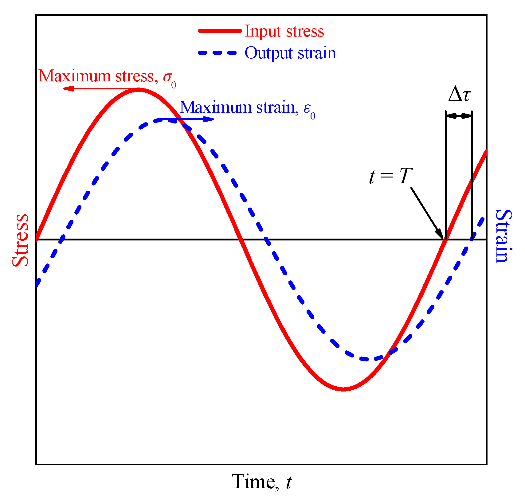
2.4. Computation of Dynamic Properties

The MMNC and the CF-reinforced MMNC models were discretized using quadratic 3D solid FEs and appropriate material properties were assigned to each different phase according to the values presented in Table 1. The MMNCs were examined in a first-level analysis using a variety of RVEs such as those shown in Figure 3. In a second-level analysis, the CF-reinforced MMNCs were simulated by utilizing the FE models that are illustrated in Figure 4. For the case of CF-reinforced MMNCs, the CNOs/α-Ti matrix was treated as a continuum medium using the dynamic properties that were computed from the first-level analysis. The equation of motion for a given RVE may be written in the below matrix form [27,28]:
M U ¨ + C U ˙ + K U = F
where M , C , and K are the structural mass, damping, and stiffness matrix, respectively, while U ¨ , U ˙ , U , and F are the nodal acceleration, velocity, displacement, and applied load vector, respectively.
To define the damping matrix C appearing in Equation (3), the Rayleigh approximation [27,28,40] was utilized. According to Rayleigh formulation, the damping matrix C may be written as a linear combination of mass and stiffness matrices [27,28,41]:
C = α M + β K
where α and β are the multiplier coefficients of the mass and stiffness matrices.
The values of the α and β multipliers should produce the desired damping ratio ζ at some circular frequency ω = 2πf. In order for this to be satisfied, it may be proved that the damping ratio ζ should be linearly dependent on the coefficients α and β as follows [18,27,40]:
ζ = α 2 ω + β ω 2
Here, it is hypothesized that the energy dissipation ability of each material phase is expressed by a separate viscous mechanical damping. Furthermore, it is considered that the loss of energy derived by the material constituents is independent of the inertia effects. Subsequently, the β multiplier of each phase may be defined with respect to the damping ratio ζ, expressing the corresponding energy dissipation and the most dominant circular frequency ω appearing on the system, according to the following relationship:
β = 2 ζ ω = ζ π f
Following the aforementioned numerical approach, a full implicit transient analysis was performed by utilizing a constant small time step equal to Δt = 0.01f. The use of smaller time steps led to negligibly different numerical outputs, meaning that the chosen time increment was fine enough to lead to convergent solutions. Most of the numerical predictions could be achieved by comparing the time variation in the average nodal normal strain on the loaded RVE face ε(t) with the time variation in the applied normal stress σ(t) on the same face. In contrast, characteristic time variations in the input stress and the output strain, under the influence of damping and consequent energy dissipation phenomena, are depicted in Figure 5.
According to the input stress and output strain time variations and the time lag Δτ which was observed between them, several dynamic properties may be computed. First of all, the phase shift, denoted as δ, between input stress and output strain may be estimated by using the time lag Δτ from Figure 5 via the following relationship:
δ = 2 π f Δ τ
Then, the loss factor tanδ, the storage modulus E′, and the loss modulus E″ may be evaluated, respectively, by [41]:
tan δ = tan 2 π f Δ τ
E = σ 0 ε 0 cos δ
E = σ 0 ε 0 sin δ
where σ0 and ε0 are the maximum of the input normal stress and the maximum (average nodal) of the output normal strain on the loaded boundary of the RVE models, respectively.
The ratio of the maximum stress to the maximum average nodal strain σ0/ε0 represents the elastic modulus or, equivalently, the stiffness of the MMNCs. The Poisson ratio of a given nanocomposite RVE may be calculated by the ratio of the average nodal normal strain on an externally nonloaded RVE face to the average nodal normal strain at the externally loaded RVE face.

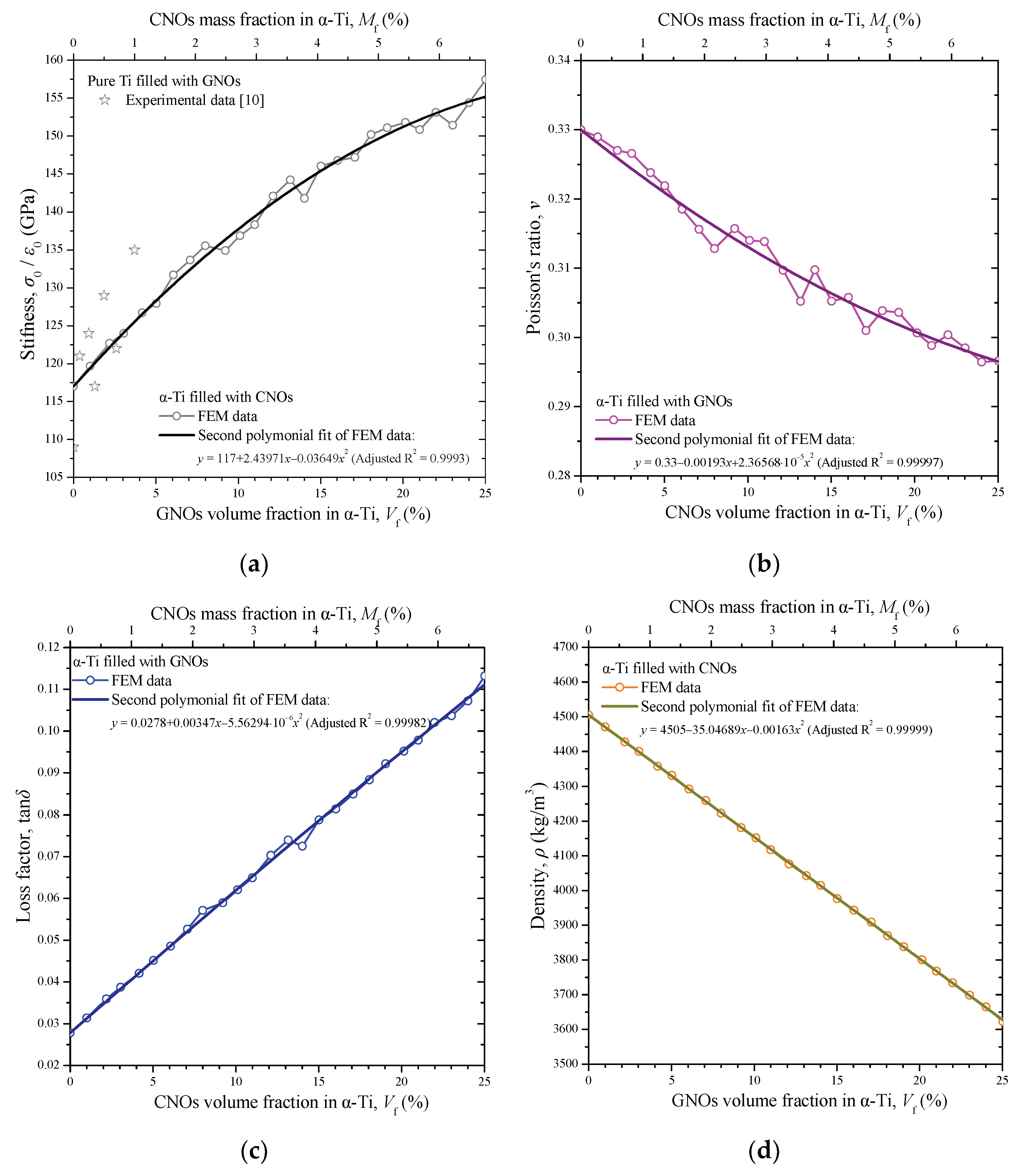
3. Numerical Results and Discussion

The current computational results, as previously mentioned, were obtained in two levels of analysis, which are visually summarized in Figure 6.
During the first level of analysis, the CNOs/α-Ti nanocomposite FE models were simulated using transient implicit analysis for various volume fractions Vf. All computations were performed for an indicative load frequency of f = 100 Hz. The time variations in the average nodal normal strain on the loaded face of the RVEs are shown in Figure 7 for five different values of volume fractions Vf. It may be observed that the higher the volume fraction Vf of the CNOs within the pure metallic matrix, the lower the maximum output strain ε0 and the longer the time lag Δτ, indicating a higher MMNC stiffness σ0/ε0 and loss factor tanδ, respectively.
Figure 8a–d present the volume fraction variations in the MMNCs stiffness σ0/ε0, Poisson’s ratio v, loss factor tanδ, and density ρ, respectively. For a better understanding of the CNOs’ influence, the axis of the independent variable in the material property diagrams was scaled not only according to the volume fraction Vf but also to the mass fraction Mf, which is defined as follows:
M f = ρ CNO V CNO ρ CNO V CNO + ρ α Ti V α Ti
where ρCNO and ρα-Ti are the densities of the CNO nanofillers and the α-Ti matrix, respectively, given in Table 1.
The volume fraction variations, especially in Figure 8a,b, are characterized by small fluctuations. This is due to the fact that the FE models were created by applying a random distribution of the CNO nanofillers in a finite box space. However, the overall trend in all variations becomes more clear when fitted with second-order polynomial functions represented by solid lines. According to Figure 8a, a significant increase in the nanocomposite stiffness was observed as the volume fraction of the CNOs attains higher values. However, the slope of increase is slightly reduced for higher volume fractions. Figure 8a includes some experimental data [10] concerning a Ti matrix nanocomposite reinforced with onion-like carbon nanoparticles at mass fractions of about 0.1 to 1.0%. Generally, the maximum relative difference between the present numerical predictions and the specific measurements was about 8%. Unfortunately, due to the novelty of the present investigation apart from the experimental data points regarding the MMNC elastic modulus, illustrated in Figure 8a, no further relevant comparable results may be found elsewhere for the investigated MMNC including its damping properties. The Poisson ratio, depicted in Figure 8b, initially shows a decreasing linear dependency on the volume fraction, whereas it presents a stabilization tendency for higher nanofiller concentrations. According to Figure 8c, the loss factor of the MMNC was almost linearly increased up to the volume fraction of 25%. For this maximum tested volume fraction and the vibrating frequency of 100 Hz, a great increase in the loss factor of α-Ti was achieved due to the addition of the CNOs. Finally, as expected, the density of the MMNC filled with CNOs shown in Figure 8d reduced significantly and linearly as the reinforcing content was increased, due to the fact that graphitic materials are much lighter than Ti.
Substituting the fitting curves included in Figure 8a,c into Equations (9) and (10) allows the prediction of the volume fraction variations in the storage and loss moduli shown in Figure 9a,b, respectively. The volume fraction variation in the storage modulus E′ of the MMNC followed the overall corresponding behavior of the stiffness. On the other hand, the loss modulus E″ showed an almost increasing linear behavior which, however, was characterized by a slight slope increase as the volume fraction rose. This phenomenon is perhaps explained by the increased porosity that the MMNC exhibited as the number of hollow nanofillers within the matrix was augmented. Figure 10 presents some indicative contour maps regarding the equivalent von Mises stress, σvM, regarding two of the investigated RVEs at a volume fraction of 10% (Figure 10a) and 25% (Figure 10b) and at the time instant t = 0.8T = 0.08 s, i.e., near the peak of the observed stress concentrations. Note that the von Mises stress values σvM at the scale bars are nondimensionalized by dividing them with the maximum applied stress σ0. It may be noticed that the maximum equivalent stresses were observed within the graphene-based nanoparticles relieving the matrix component. As the volume fraction was increased, the stresses were distributed to more nanoparticles. As a result, the maximum von Mises stress was lower for the case Vf = 0.25.
To continue to the second-level analysis concerning the characterization of energy dissipation of the CNOs/α-Ti nanocomposite reinforced with the T300 CFs at f = 100 Hz, the predicted properties from Figure 8a–d were used as the input. The aim was to develop RVEs in which the MMNC matrix was modeled as a continuum solid phase using the macroscopic properties defined by these figures. The MMNC matrix made of CNOs/α-Ti was tested at the volume fractions Vf = 0, 0.10, 0.15, 0.20, and 0.25. On the other hand, two different cases regarding the volume fraction of the CFs in the CNO/α-Ti matrix were investigated, i.e., VfCF = 0.05, 0.10. Figure 11a–d present the variation in the stiffness σ0/ε0, the loss factor tanδ, the storage modulus E′, and the loss modulus E″ of the CF-reinforced MMNCs, respectively, with regard to the CNO volume fraction Vf and the CF volume faction VfCF.
Generally, all presented properties increased as the volume fraction Vf rose. Nevertheless, the slope of the increase in the curves that correspond to the stiffness and storage modulus seems to reduce as Vf reaches 25%. Instead, the loss factor and loss modulus curves have an almost linear ascending behavior. As in the case of simple MMNCs, and perhaps due to the impact of porosity, their slope shows a marginal increase as the Vf increases. It becomes clear that the damping capacity, expressed by the loss factor, of the MMNC becomes lower with the addition of the CFs. In contrast, the higher the fiber volume fraction VfCF, the higher the stiffness of the CF-reinforced nanocomposite. In any case, the α-Ti offered better energy dissipation properties when reinforced with CNOs. However, most of the positive influence of the CNOs on the loss factor of the titanium matrix was not lost due to the addition of fiber reinforcements, which simultaneously provided a significant stiffness enhancement to the material system. An important observation is the fact that the addition of carbon fibers in an α-Ti matrix filled with CNO leads to an improvement in the storage modulus but to a reduction in the loss factor due to the inherent high effective elastic modulus and low loss factor of the carbon fibers, respectively. Some contour plots of the dimensionless equivalent von Mises stress σ0vM for two CF-reinforced MMNC RVEs at a VfCF equal to 0.05 and 0.10 are illustrated in Figure 12a,b, respectively. The contours correspond to the highest tested CNO volume fraction Vf = 0.25 and to the time point t = 0.0077 s around which stress peaks occur. As illustrated, for both the CF volume fraction cases, the maximum equivalent stress was detected in the fibers. In addition, the increase in the CF concentration led to a significant decrease in the level of von Mises stresses.

4. Conclusions

A 3D FEM procedure was developed to evaluate the damping characteristics of nanocomposites made of α-titanium filled with hollow CNOs. A structural implicit transient FE analysis was performed for RVEs that contained hollow CNOs, using corresponding material properties for the nanofillers, to approximate the loss factor and the stiffness behavior of the CNO/α-Ti nanocomposites at a variety of volume fractions. Using the numerical results of the CNOs/α-Ti nanocomposites, consequential CF-reinforced MMNCs were investigated via the use of appropriate RVEs. It was proved that the loss factor of the titanium was greatly increased when filled with CNOs due to the high internal friction of multilayer graphene-like walls of the CNOs as well as the internal voids of the CNOs leading, indirectly, to the presence of porosity. According to the investigation, the addition of 5 weight percent of CNOs improved the damping capacity of α-Ti at 100 Hz by up to 60%. In addition, the tested CF-reinforced MMNCs demonstrated a slightly reduced damping capacity compared to simple CNOs/α-Ti nanocomposites; however, they also presented a better overall stiffness performance. Independent experimental evidence from tensile tests conducted in equivalent nanocomposite material systems was used for qualitative comparisons. Overall, both theoretical and experimental analyses revealed the same stiffness behavior of the MMNCs. The main outcome is that CNOs seem to be excellent filler candidates for improving the damping behavior of titanium alloys, which is very important for the automotive and aerospace industry. Inspired by the present findings, further experimental research is required regarding the damping characterization of the proposed MMNC systems, which ought to be made in the near future. Future work may also include the validation of the present findings by using atomistic-based computational methods such as molecular dynamics.

Author Contributions

Conceptualization, G.I.G.; methodology, G.I.G.; software, G.I.G. and N.D.B.; validation, G.I.G. and N.D.B.; formal analysis, G.I.G. and N.D.B.; investigation, G.I.G. and N.D.B.; resources, G.I.G. and N.D.B.; data curation, G.I.G. and N.D.B.; writing—original draft preparation, G.I.G. and N.D.B.; writing—review and editing, G.I.G. and N.D.B.; visualization, G.I.G. and N.D.B. All authors have read and agreed to the published version of the manuscript.

Funding

This research received no external funding.

Data Availability Statement

The data that support the findings of this article are available from the corresponding author upon reasonable request.

Conflicts of Interest

The authors declare no conflict of interest.

References

  1. Tjong, S.C. Recent progress in the development and properties of novel metal matrix nanocomposites reinforced with carbon nanotubes and graphene nanosheets. Mater. Sci. Eng. R Rep. 2013, 74, 281–350. [Google Scholar]
  2. Yoo, S.C.; Lee, D.; Ryu, S.W.; Kang, B.; Ryu, H.J.; Hong, S.H. Recent progress in low-dimensional nanomaterials filled multifunctional metal matrix nanocomposites. Prog. Mater. Sci. 2023, 132, 101034. [Google Scholar]
  3. Ghavanloo, E.; Rafii-Tabar, H.; Kausar, A.; Giannopoulos, G.I.; Fazelzadeh, S.A. Experimental and computational physics of fullerenes and their nanocomposites: Synthesis, thermo-mechanical characteristics and nanomedicine applications. Phys. Rep. 2023, 996, 1–116. [Google Scholar]
  4. Mykhailiv, O.; Zubyk, H.; Plonska-Brzezinska, M.E. Carbon nano-onions: Unique carbon nanostructures with fascinating properties and their potential applications. Inorganica Chim. Acta 2017, 468, 49–66. [Google Scholar]
  5. Ajay Kumar, P.; Vishnu Namboodiri, V.; Joshi, G.; Mehta, K.P. Fabrication and applications of fullerene-based metal nanocomposites: A review. J. Mater. Res. 2021, 36, 114–128. [Google Scholar]
  6. Zeiger, M.; Jäckel, N.; Mochalin, V.N.; Presser, V. Review: Carbon onions for electrochemical energy storage. J. Mater. Chem. A 2016, 4, 3172–3196. [Google Scholar]
  7. He, C.; Zhao, N.; Shi, C.; Du, X.; Li, J.; Cui, L. A practical method for the production of hollow carbon onion particles. J. Alloys Compd. 2006, 425, 329–333. [Google Scholar] [CrossRef]
  8. Klose, M.; Pinkert, K.; Zier, M.; Uhlemann, M.; Wolke, F.; Jaumann, T.; Jehnichen, P.; Wadewitz, D.; Oswald, S.; Eckert, J.; et al. Hollow carbon nano-onions with hierarchical porosity derived from commercial metal organic framework. Carbon 2014, 79, 302–309. [Google Scholar]
  9. Ruan, C.; Li, Z.; Zhang, D.; Yuan, X.; Liang, C.; Chang, Y.; Huang, H.; Xu, L.; Chen, M. A scalable chemical vapor deposition synthesis of high purity hollow carbon onions. Carbon 2020, 161, 622–628. [Google Scholar] [CrossRef]
  10. Fan, K.; Zhang, F.; Shang, C.; Saba, F.; Yu, J. Mechanical properties and strengthening mechanisms of titanium matrix nanocomposites reinforced with onion-like carbons. Compos. Part A Appl. Sci. Manuf. 2020, 132, 105834. [Google Scholar]
  11. Aissou, T.; Casteignau, F.; Braidy, N.; Veilleux, J. Synthesis and Growth of Onion-Like Polyhedral Graphitic Nanocapsules by Thermal Plasma. Plasma Chem. Plasma Process. 2023, 43, 413–427. [Google Scholar] [CrossRef]
  12. Baowan, D.; Thamwattana, N.; Hill, J.M. Continuum modelling of spherical and spheroidal carbon onions. Eur. Phys. J. D 2007, 44, 117–123. [Google Scholar] [CrossRef]
  13. Todt, M.; Bitsche, R.D.; Hartmann, M.A.; Fischer, F.D.; Rammerstorfer, F.G. Growth limit of carbon onions—A continuum mechanical study. Int. J. Solids Struct. 2014, 51, 706–715. [Google Scholar] [CrossRef]
  14. Izadi, R.; Ghavanloo, E.; Nayebi, A. Elastic properties of polymer composites reinforced with C60 fullerene and carbon onion: Molecular dynamics simulation. Phys. B Condens. Matter 2019, 574, 311636. [Google Scholar] [CrossRef]
  15. Pereira Júnior, M.L.; da Cunha, W.F.; de Sousa Junior, R.T.; Amvame Nze, G.D.; Galvão, D.S.; Ribeiro Júnior, L.A. Dynamics and structural transformations of carbon onion-like structures under high-velocity impacts. Carbon 2022, 189, 422–429. [Google Scholar] [CrossRef]
  16. Zuo, Y.Q.; Smith, D.J.; Partridge, P.G. Damping capacity of laminates composed of layers of titanium alloy and titanium alloy MMC. Mater. Sci. Technol. 1998, 14, 518–521. [Google Scholar] [CrossRef]
  17. Kalyan Phani, M.; Kumar, A.; Arnold, W.; Samwer, K. Elastic stiffness and damping measurements in titanium alloys using atomic force acoustic microscopy. J. Alloys Compd. 2016, 676, 397–406. [Google Scholar] [CrossRef]
  18. Meng, X.; Zhao, Y.; Lu, J.; Huang, S.; Zhou, J.; Su, C. Improvement of damping property and its effects on the vibration fatigue in Ti6Al4V titanium alloy treated by warm laser shock peening. Metals 2019, 9, 746. [Google Scholar] [CrossRef]
  19. Liu, W.; Wang, N.; Chen, Y.; Hou, Z.; Zhao, Q.; Ouyang, W.; Kang, Y.; Wu, G.; Zhu, L.; Zhao, Y. Damping behavior of typical titanium alloys by varied frequency micro harmonic vibration at cryogenic temperatures. J. Mater. Res. Technol. 2022, 21, 3746–3755. [Google Scholar] [CrossRef]
  20. Lahiri, D.; Das, S.; Choi, W.; Agarwal, A. Unfolding the damping behavior of multilayer graphene membrane in the low-frequency regime. ACS Nano 2012, 6, 3992–4000. [Google Scholar] [CrossRef]
  21. Zhang, J.; Gungor, M.N.; Lavernia, E.J. The effect of porosity on the microstructural damping response of 6061 aluminium alloy. J. Mater. Sci. 1993, 28, 1515–1524. [Google Scholar] [CrossRef]
  22. Panteliou, S.D.; Dimarogonas, A.D. Damping associated with porosity and crack in solids. Theor. Appl. Fract. Mech. 2000, 34, 217–223. [Google Scholar] [CrossRef]
  23. Tabie, V.M.; Li, C.; Saifu, W.; Li, J.; Xu, X. Mechanical properties of near alpha titanium alloys for high-temperature applications–a review. Aircr. Eng. Aerosp. Technol. 2020, 92, 521–540. [Google Scholar]
  24. Klepikov, V.F.; Lonin, Y.F.; Ponomarev, A.G.; Startsev, O.A.; Uvarov, V.T. Physical and mechanical properties of titanium alloy VT1-0 after high-current electron beam irradiation. Probl. At. Sci. Technol. 2015, 96, 39–42. [Google Scholar]
  25. Konovalov, S.; Komissarova, I.; Ivanov, Y.; Gromov, V.; Kosinov, D. Structural and phase changes under electropulse treatment of fatigue-loaded titanium alloy VT1-0. J. Mater. Res. Technol. 2019, 8, 1300–1307. [Google Scholar] [CrossRef]
  26. Panin, A.V.; Kazachenok, M.S.; Kazantseva, L.A.; Martynov, S.A.; Panina, A.A.; Lobova, T.A. Microstructure and Phase Composition of VT1-0, VT6, and VT14 Titanium Alloys Produced by Wire-Feed Electron-Beam Additive Manufacturing. J. Surf. Investig. 2022, 16, 983–991. [Google Scholar] [CrossRef]
  27. Ansys, Workbench 2020 R2. Available online: https://www.ansys.com/products/ansys-workbench (accessed on 1 June 2023).
  28. Lee, H.-H. Finite Element Simulations with ANSYS Workbench 2020; SDC Publications: Mission, KS, USA, 2020. [Google Scholar]
  29. Ansari, R.; Ahmadi, M.; Rouhi, S. Impact resistance of short carbon fibre-carbon nanotube-polymer matrix hybrid composites: A stochastic multiscale approach. Proc. Inst. Mech. Eng. Part L J. Mater. Des. Appl. 2021, 235, 1925–1936. [Google Scholar] [CrossRef]
  30. Strozzi, M.; Giacomobono, R.; Rubini, R.; Cocconcelli, M. Preliminary orthotropic elastic model for the study of natural frequencies and mode shapes of a 3D printed Onyx thin circular cylindrical shell. Int. J. Mech. Control 2020, 21, 51–62. [Google Scholar]
  31. Shinde, V.V.; Wang, Y.; Salek, M.F.; Auad, M.L.; Beckingham, L.E.; Beckingham, B.S. Material Design for Enhancing Properties of 3D Printed Polymer Composites for Target Applications. Technologies 2022, 10, 45. [Google Scholar] [CrossRef]
  32. Zheng, Y.; Huang, X.; Chen, J.; Wu, K.; Wang, J.; Zhang, X. A review of conductive carbon materials for 3d printing: Materials, technologies, properties, and applications. Materials 2021, 14, 3911. [Google Scholar] [CrossRef]
  33. Mileiko, S. Carbon-Fibre/Metal-Matrix Composites: A Review. J. Compos. Sci. 2022, 6, 297. [Google Scholar] [CrossRef]
  34. Mileiko, S.T.; Rudnev, A.M.; Gelachov, M.V. Carbon-fibre/titanium silicide interphase/titanium-matrix composites: Fabrication, structure and mechanical properties. Compos. Sci. Technol. 1995, 55, 255–260. [Google Scholar] [CrossRef]
  35. Even, C.; Arvieu, C.; Quenisset, J.M. Powder route processing of carbon fibres reinforced titanium matrix composites. Compos. Sci. Technol. 2008, 68, 1273–1281. [Google Scholar] [CrossRef]
  36. Lv, S.; Li, J.S.; Li, S.F.; Kang, N.; Chen, B. Effects of heat treatment on interfacial characteristics and mechanical properties of titanium matrix composites reinforced with discontinuous carbon fibers. J. Alloys Compd. 2021, 877, 160313. [Google Scholar]
  37. Mileiko, S.T.; Kolchin, A.A.; Krivtsov, D.I.; Galyshev, S.N.; Prokopenko, N.A.; Shakhlevich, O.F.; Petrova, O.V. Carbon-fibre/titanium-matrix composites of a hierarchical microstructure. Compos. Part A Appl. Sci. Manuf. 2022, 155, 106817. [Google Scholar] [CrossRef]
  38. Ng, S.-P.; Tse, P.-C.; Lau, K.-J. Numerical and experimental determination of in-plane elastic properties of 2/2 twill weave fabric composites. Compos. Part B Eng. 1998, 29, 735–744. [Google Scholar] [CrossRef]
  39. Lesieutre, G.A.; Eckel, A.J.; DiCarlo, J.A. Damping of bromine-intercalated P-100 graphite fibers. Carbon 1991, 29, 1025–1032. [Google Scholar] [CrossRef]
  40. Rahul, B.; Dharani, J.; Balaji, R. Optimal method for determination of rayleigh damping coefficients for different materials using modal analysis. Int. J. Veh. Struct. Syst. 2021, 13, 102–111. [Google Scholar]
  41. Meyers, M.; Chawla, K. Mechanical Behaviors of Materials, 2nd ed.; Cambridge University Press: New York, NY, USA, 2009; pp. 124–125. [Google Scholar]
Figure 1. A CNO modeled as an isotropic hollow spherical nanoparticle: (a) geometry and (b) FE mesh.
Metals 13 01577 g001
Figure 2. A CF modeled as an orthotropic solid microcylinder: (a) geometry and (b) FE mesh.
Metals 13 01577 g002
Figure 3. A nanocomposite RVE made of α-Ti filled with CNOs: (a) geometry for Vf = 0.10, (b) FE mesh for Vf = 0.10, (c) geometry for Vf = 0.25, and (d) FE mesh for Vf = 0.25.
Metals 13 01577 g003
Figure 4. A nanocomposite RVE made of the CNOs/α-Ti reinforced with CFs: (a) Geometry for VfCF = 0.05, (b) FE mesh for VfCF = 0.05, (c) geometry for VfCF = 0.10, and (d) FE mesh for VfCF = 0.10.
Metals 13 01577 g004
Figure 5. The time lag between input stress and output strain, which was caused by the overall damping of the nanocomposite.
Metals 13 01577 g005
Figure 6. The two-level analysis proposed for the characterization of the mechanical and damping behavior of different types of MMNCs filled with CNOs.
Metals 13 01577 g006
Figure 7. Computed time variations in output strain of the CNOs/α-Ti RVEs at a variety of volume fractions.
Metals 13 01577 g007
Figure 8. Volume fraction variations in (a) the stiffness σ0/ε0, (b) Poisson’s ratio ν, (c) the loss factor tanδ, and (d) the density ρ of the CNOs/α-Ti nanocomposites.
Metals 13 01577 g008
Figure 9. Volume fraction variations in (a) the storage modulus E′ and (b) the loss modulus E″ of the CNOs/α-Ti nanocomposites.
Metals 13 01577 g009
Figure 10. Contours of the equivalent von Mises stress σvM at time t = 0.8T for the CNOs/α-Ti and at a volume fraction Vf of (a) 10% and (b) 25%.
Metals 13 01577 g010
Figure 11. The variation in (a) the stiffness σ0/ε0, (b) the loss factor tanδ, (c) the storage modulus E′, and (d) the loss modulus E″ of the CNOs/α-Ti nanocomposites reinforced with CFs versus the CNOs volume fraction and for two CF volume fractions.
Metals 13 01577 g011
Figure 12. Contours of the equivalent von Mises stress σvM at time t = 0.77T for the CNOs/α-Ti reinforced with CFs at a CNOs volume fraction Vf of 25% and a CF volume fraction VfCF of (a) 5% and (b) 10%.
Metals 13 01577 g012
Table 1. Utilized material properties for each basic phase in the FEM models.
Material/PhaseBehaviorDensity
(kg/m3)
Elastic Constant
(GPa)
Poisson’s Ratio
(−)
Loss Factor
(−)
ρExxEyyEzzGxyGyzGxzνxyνyzνxztanδ
α-TiIsotropic450511711717743.98543.98543.9850.330.330.330.0278
CNOsIsotropic226738710501050442.66442.66442.660.1860.1860.1860.518
CFsOrthotropic215017.2417.2417.247.17.17.10.2140.2140.2140.000159
Disclaimer/Publisher’s Note: The statements, opinions and data contained in all publications are solely those of the individual author(s) and contributor(s) and not of MDPI and/or the editor(s). MDPI and/or the editor(s) disclaim responsibility for any injury to people or property resulting from any ideas, methods, instructions or products referred to in the content.

