Article

Optimization of Oxygen Injection Conditions with Different Molten Steel Levels in the EAF Refining Process by CFD Simulation

by
Perawat Thongjitr
1,
Pruet Kowitwarangkul
1,*,
Yotsakorn Pratumwal
2 and
Somboon Otarawanna
2
1
The Sirindhorn International Thai-German Graduate School of Engineering (TGGS), King Mongkut’s University of Technology North Bangkok (KMUTNB), Bangkok 10800, Thailand
2
National Metal and Materials Technology Center (MTEC), National Science and Technology Development Agency (NSTDA), Pathum Thani 12120, Thailand
*
Author to whom correspondence should be addressed.
Metals 2023, 13(9), 1507; https://doi.org/10.3390/met13091507
Submission received: 29 June 2023 / Revised: 31 July 2023 / Accepted: 20 August 2023 / Published: 22 August 2023
(This article belongs to the Special Issue Process and Numerical Simulation of Oxygen Steelmaking)

Abstract

:
In electric arc furnace (EAF) steelmaking, oxygen jets play a crucial role in controlling stirring ability, chemical reactions, and energy consumption. During the EAF lifetime, refractory wear leads to a decrease in the molten steel level and an increase in the nozzle-to-steel distance, thereby negatively affecting the overall energy efficiency of the process. The objective of this study is to optimize the energy efficiency of the EAF refining process by adjusting the nozzle flow conditions and conducting an analysis of jet performance using computational fluid dynamics (CFD) simulation. Three types of injection jets were considered: the conventional jet, the CH4 coherent jet, and the CH4 + O2 coherent jet. The findings reveal that the shrouded flame of the coherent jet enhances jet performance by maintaining the maximum velocity, extending the potential core length, and increasing the penetration depth in the molten steel bath. To maintain the jet performance in response to an increased nozzle-to-steel distance resulting from refractory wear, transitions from the conventional jet to the CH4 coherent jet and the CH4 + O2 coherent jet are recommended once the nozzle-to-steel distance increases from its initial level of 1000 mm to 1500 mm and 2000 mm, respectively.

Graphical Abstract

1. Introduction

In the recycled steel industry, electric arc furnaces (EAF) are operated using electrical and chemical energy. In recent years, the steelmaking process has been continuously developed to increase energy efficiency and decrease power consumption. Various techniques have been used to reduce specific electrical energy consumption, such as scrap preheating, direct input of hot metal, supersonic oxygen (O2) jet injection, and the slag foaming technique. One of the methods used to substitute electrical energy and reduce production costs is the use of chemical energy from a supersonic O2 jet [1,2,3,4,5]. However, the efficiency of supersonic O2 jet drops due to the descending level of molten steel inside the EAF after the refractory has significantly worn.
A supersonic jet is employed in the melting and refining process to increase energy efficiency, oxidize the dissolved impurities in the molten steel in the EAF, and generate heat, which contributes to the consequent electrical energy savings [6,7,8,9]. The chemical reactions from injecting O2 and carbon into the molten bath increase the efficiency of the steelmaking process and decrease melting time and electrode consumption. However, excessive O2 injection has negative effects, including yield loss of metal, increased FeO content, and lower slag viscosity. This results in thermal energy loss and refractory wear [5,10]. There are two types of supersonic jet: the conventional supersonic jet and the coherent supersonic jet. The conventional supersonic jet is the injection of O2 gas into the molten steel bath [11]. The core velocity of a supersonic jet continuously decreases along the distance from the nozzle to the molten steel bath due to the entrainment between the main O2 jet and the surrounding environment gas. This provides a lower impact on momentum and oxidation rate [12]. The limitation of the conventional jet is the short potential core length.
One technique to enhance the efficiency of the conventional jet is to reduce the surrounding resistance of the supersonic jet by the implementation of a coherent jet. In the refining process, the coherent supersonic jet technique employs a shrouding nozzle to deliver an O2 supersonic jet into the molten steel bath. The shrouded gas flow, which is a mixture of fuel (CH4) and O2 surrounding the main O2 jet, produces a combustion flame. This flame creates a low-density zone at the core of the jet. The potential core length of the jet is significantly increased by a shrouding flame that maintains the supersonic jet. As a result, the O2 jet is able to penetrate deeper into the molten steel bath, thereby enhancing the efficiency of O2 delivery [1,13]. This technique outperforms conventional supersonic jets in terms of both stirring ability and energy efficiency in the refining process [12].
Previous research [4,11,12,13,14] applied computational fluid dynamics (CFD) simulation to physical water models and/or combustion experiments to study the characteristics of O2 supersonic jets. The O2 jet parameters are crucial in the steelmaking process because they affect stirring, chemical reactions, energy consumption, and foaming slag formation [9,15]. A study by Liu et al. in 2020 [12] investigated the characteristics of the O2 lance structure on supersonic jets using CFD simulation and combustion experiments. Their results indicated that a different lance structure design is able to prolong the velocity potential core length, which enhances the steelmaking process efficiency. In 2016, Liu et al. [16] reported that increasing the flow rate of the shrouding nozzle results in the prolongation of the potential core length of the jet. Similarly, Zhao et al. [17,18,19] examined the efficiency of a supersonic coherent jet in which a supersonic shrouding nozzle surrounds the main jet. They found that the use of a supersonic coherent jet significantly enhances the potential core length of the main jet. Moreover, research articles authored by Zhao et al. [20] in 2017 and Liu et al. [21] in 2018 examined coherent jets with various parameters for shrouding gas without a combustion flame. Both articles found that the parameters of the shrouding gas injection played a crucial role in protecting the main O2 jet from the ambient gas resulting in reduced jet expansion and an increase in jet length. Gas temperature is another important factor affecting the potential core length. In 2016, Liu et al. [7] investigated the potential core length of the jet under different main O2 temperatures. In their study, increased main O2 temperature led to a higher axial velocity but a lower potential core length. Various research studies have been conducted to improve O2 injection and shrouding flame techniques for reducing electrical consumption during the melting and refining processes [8,12,13]. The utilization of coherent jet technology has shown promising results in lowering electricity consumption in the steelmaking process. Additionally, coherent jet technology offers various metallurgical and operational benefits, such as shorter processing times, cost-effectiveness, higher efficiency, and improved product quality [22]. For instance, Sung et al. [4] designed an injector system for the EAF, modifying the nozzle position to reduce the distance between the nozzle outlet and the molten steel bath. This modification led to a reduction in electrical energy usage of 5 kWh/ton. Similarly, Megahed et al. [23] and Memoli et al. [24] adjusted the nozzle location and flow rate of O2 injection resulting in decreased electrical consumption and refractory usage along with increased productivity. These studies demonstrated the potential of optimizing jet injection techniques to enhance energy efficiency and overall performance in the steelmaking process.
Based on the literature review, three jet injection techniques are commonly used in EAF steelmaking: the conventional jet, the CH4 coherent jet, and the CH4 + O2 coherent jet techniques. These coherent jet technique enhances the stirring capability of molten steel by injecting gas shielding around the main jet. Table 1 presents a summary of research articles pertaining to these techniques. Most of the research involved comparing the conventional jet and the coherent jet and modifying the shape and injection parameters of the nozzle, as well as alterations to the gas mixture ratio in the nozzle.
All the studies listed in Table 1 focused on comparing one or two types of injection jets. As far as the current authors know, there have been no direct reports directly comparing the performances of these three injection types under real steel plant conditions. Therefore, this study employed CFD to predict the flow characteristics of three injection jet types installed at a steelmaking plant. This study also examines and verifies the most applicable turbulence models. Furthermore, optimization of flow parameters was performed considering the different molten steel levels caused by EAF refractory wear.

2. Methodology

In this study, an 85-ton capacity EAF located at a steelmaking plant in Thailand, i.e., Millcon Steel PLC., was chosen as a case study. The furnace has a diameter of 6 m. In the refining process, three O2 jets were used, as shown in Figure 1. The inclined jets were installed in the EAF furnace wall at an angle of 42° from the horizontal and 670 mm above the molten steel level inside the furnace, as illustrated in Figure 2a. The conventional jet was used in the refining process of this steel mill, with a maximum flow rate of 1800 Nm3/h. The O2 consumption in the refining process accounted for approximately 40 percent of the total O2 consumption.
The level of molten steel in the furnace decreased with EAF lifetime due to increasing wear in the refractory wall. Figure 2a shows that the new furnace has a distance between the nozzle exit and the molten steel of 1000 mm. Whereas, Figure 2b shows the refractory wear at the lower shell after 600 heats. This resulted in an increase in the distance between the nozzle exit and the molten steel to 2000 mm.
Based on the production data from approximately 3500 heat samples at this plant, a longer EAF lifetime led to higher O2 and electrical consumption during the refining process (Figure 3). For the initial 200 heats, the average O2 consumption and the average electrical consumption were 380 kWh/ton of billet and 12 Nm3/ton of billet, respectively. After 600 heats, the average O2 consumption and the average electrical consumption rose significantly to 392 kWh/ton of billet and 13.6 Nm3/ton of billet, respectively.

2.1. Numerical Method

In this study, the computer equipped with an Intel Core i9 (10th Gen) processor and 48 GB of memory was used for simulation. The computational time for each case was approximately 100 h. CFD software, ANSYS Fluent 2020R2, was employed to predict the characteristics of the O2 jet in the refining process, which has a high ambient temperature and is difficult to measure inside the furnace. The phenomena of the conventional jet and the coherent jet were simulated.
The numerical simulation was calculated by integrating the Reynolds-averaged Navier–Stokes equations. The average mass, momentum, and energy conservation equations of the Navier–Stokes equations were as follows:
Mass conservation equation:
ρ t + ρ u i x i = 0
Momentum conservation equation:
t ρ u i + x j ρ u i u j = P f x i + x j ( τ ij ρ u i u j ) -
Energy conservation equation:
t ρ E + x i u i ρ E + ρ = x j k eff T x j + u i τ ij eff + S h
where ρ is the gas density, E is the total energy of the gas, ui and uj are the average velocity components at the i and j directions, Pf is the pressure of the fluid, ui′ and uj′ are the fluctuating velocity components, keff is the effective thermal conductivity, T is the temperature of the fluid, Sh is the internal source of energy, and τ ij is the viscous stress tensor on the cell surface measured using the molecular viscosity.
In the simulation setup, the gas phases of O2 and CH4 were defined as ideal gases because the O2 lance passed the primary nozzle; its high-pressure energy, temperature, and density also changed. As a result, the ideal gas phase should be established for the calculations in the following equation:
ρ = PM nRT
where, ρ , P, M, n, R, and T are density, total pressure, mass, mole number of the gas, ideal gas state constant being 8.314, and temperature, respectively.
To study the flow field characteristic of the O2 supersonic jet, the RNG k-ε turbulence model is derived from the instantaneous Navier–Stokes equations in the simulation process. The analytical derivation results in a model with constants different from those in the standard k-ε model and additional terms and functions in the transport equations for k and ε.
t ρ k + ( ρ k u i ) x i = x j α k μ eff k x j + G k + G b ρ ε + Y M +   S k
t ρ ε + ( ρ ε u i ) x i = x j α ε μ eff ε x j C ε 1 ε k G k + C 3 ε G b C 2 ε ρ ε 2 k R ε +   S ε
where C ε 1 , and C ε 2 , are the constants for the model, and their values are 1.42 and 1.68. Gk is the generation of turbulence kinetic energy due to mean velocity gradients, Gb is the generation of turbulence kinetic energy due to buoyancy, Ym is the contribution of the fluctuating dilatation in compressible turbulence to the overall dissipation rate, α k and α ε are the inverse effective Prandtl number for k and ε , respectively. RNG k- ε turbulence model, C μ = 0.0845 is used, and turbulent viscosity was computed by the following equation:
μ t = C μ ρ k 2 ε
A species transport model was applied to solve the conservation equations for all chemical species. The local mass fraction of each species, Yj, is solved through the solution to the convection–diffusion equation. The conservation equations are presented below:
ρ u Y i =   J i + R i
J i = ρ D i , m + u t Sc t Y i D T , i T T
where Ri is the net rate of production of species i by chemical reactions. J i is the diffusion flux term of species i, Di;m is the diffusion coefficient for species i in the mixture, and DT;i is the thermal diffusion coefficient. Sct is the turbulent Schmidt number, which is 0.7.
To investigate the influence of the shrouding gas composition on the properties of the supersonic jet. The Eddy Dissipation (ED) model and the Eddy Dissipation Concept (EDC) model are often applied to turbulence/chemistry interactions. The EDC model provides more accuracy than ED; however, the ED model requires less computational time [6,25,31]. In this research, the eddy dissipation (ED) model is applied. Moreover, a one-step combustion reaction between CH4 and O2 is examined. The net rate of production of species i due to reaction r, Ri,r, is given in the two expressions below:
R i = v i , r M w , i A ρ ε k ( Y R v i , r M w , R )
R i =   v i , r M w , i AB ρ ε k ( P Y P j N v j , r M w , j )
where YP is the mass fraction of any product species (P), YR is the mass fraction of a particular reactant (R), A is an empirical constant equal to 4.0, and B is an empirical constant equal to 0.5.

2.2. CFD Model and Boundary Conditions

The dimensions of the supersonic jet nozzle, which consists of main O2 and straight shrouding nozzles, are illustrated in Figure 4. The throat and exit diameters of the main O2 jet are 19 mm and 27 mm, respectively. The straight shrouding nozzles with a diameter of 6 mm are arranged in two concentric rings with radii of 27 mm and 33 mm, supplying methane (CH4) and oxygen (O2), respectively.
The investigation included three types of jets, categorized as follows: First, Cases A1–A3 represent conventional jets involving O2 injection through the central main O2 jet without the presence of a shrouding nozzle injection flame (Figure 5a). Second, Cases B1–B3 correspond to CH4 coherent jets, where the main O2 injection is shielded with a shrouded flame generated using CH4 combustion (Figure 5b). Last, Cases C1–C3 refer to CH4 + O2 coherent jets, in which the main O2 injection is shielded with a shrouded flame formed by both CH4 and secondary O2 (Figure 5c).
The simulations were conducted in the 3D geometric domain. The boundary conditions are illustrated in Figure 6. The domain and its boundaries include the main O2 jet inlet, shrouding CH4 inlet, shrouding O2 inlet, outlet, and combustion zone. The domain extends 3000 mm downstream in the axial direction and 850 mm in the radial direction. The boundary is denoted by a black line representing a defined wall region. The boundary conditions at the main O2 jet inlet and shrouding nozzle inlets are adopted as mass flow inlets of each gas phase as a 100% mass fraction of O2 and CH4. The temperatures of all gas phases at the inlets are set at 298 K. The boundary condition denoted by the red lines of the combustion zone is defined as a pressure outlet condition with an ambient temperature of 1700 K and 5% backflow turbulent intensity. The initial condition of the domain is also filled with air at a temperature of 1700 K.
Table 2 presents the mass flow rate parameters for nine scenarios (Cases A1 to C3) of CFD simulation. In the initial phase of the refining process at the sample plant, the O2 flow rate gradually increased from 0.476 kg/s (A1) to a maximum level of 0.715 kg/s (A3) and remained constant for the rest of the 60% of the total refining time. Therefore, the O2 jet flow rate in Case A3 is introduced for further studies of coherent jets in the last six scenarios. The flow rate of each case in the simulation was set to a constant value. The shrouding flow rates in Cases B1 to C3 were designed based on data from the combustion injection during the scrap preheating process of the sample plant. The combustion reaction stoichiometric ratio of CH4 and O2 shrouding in Cases C1 to C3 was set to 1. It is observed that, for the present operation of the sample plant, the nozzle system contains both the main O2 jet and the shrouding nozzle, but neither has been used concurrently in a coherent jet. The designs of all the scenarios in Table 2 were conducted to introduce a technique to improve the stirring ability of the refining process by adjusting the flow conditions and flow rate parameters.
The simulations of the conventional and coherent supersonic jets were performed under steady-state conditions. The momentum and energy equations of the supersonic jet and shrouding nozzle were solved using a pressure-based solver. The wall was defined as a stationary wall with non-slip conditions. The SIMPLE algorithm scheme was employed in the pressure-velocity coupling. To improve the accuracy of the numerical simulations, a second-order upwind scheme was used for spatial discretization. To obtain significant impacts on the simulation result, a discrete ordinate (DO) model was considered for radiation phenomena. The weighted sum of gray gas (WSGG) model was calculated for the radiative heat transfer. The specific heat of a gas phase was defined as a piecewise polynomial. In this study, the energy and species equations were solved, and the convergence was verified. Convergence was obtained when the residuals were less than 10−6 for the energy and 10−4 for all the other variables. The second criterion was that the variations between consecutive iterations of temperature and velocity at the outlet downstream were within 10 K and 2 m/s, respectively.

2.3. Mesh Independence

The mesh sensitivity of the numerical model was investigated to determine an optimal number of elements for the simulation setup. In this research study, different mesh configurations were used for distinct areas. In the nozzle zone, a tetrahedral mesh was implemented. Meanwhile, a hexahedral mesh was applied in the combustion zone, as shown in Figure 7. In the central core region of the combustion zone, the mesh was refined with structured hexahedral elements, and the radius of the center core mesh refinement was defined as 55 mm from the central axial position.
The mesh independency of this study was considered using the axial velocity of the coherent jet. Figure 8a,b present the axial velocity profiles of a CH4 + O2 coherent jet of six mesh levels and velocity magnitude at a position of 2000 mm and 2500 mm from the nozzle exit. The number of elements used in this study includes 2.5 M, 2.8 M, 3.0 M, 3.6 M, 4.2 M, and 4.6 M. The simulation results provide a significant correlation with axial velocity variations of less than 2.0%. The difference in axial velocity between 3.0 M and 3.6 M was approximately 11% and 4% at positions 2000 mm and 2500 mm, respectively. Based on this investigation, the accuracy of the combustion simulation and computational time was optimized upon employing 3.6 million elements.

3. Results and Discussion

3.1. Model Validation

For the CFD modeling, the supersonic state of the main O2 jet was considered, and the flow turbulence was modeled using a Reynold-Averaged Navier–Stokes (RANS) two-equation model. As there is no consensus on the most suitable models for this type of problem, this study compared three k- ε models, i.e., standard k- ε , realizable k- ε , and RNG k- ε [1,12,13,14,21,33], and two k-ω models, i.e., standard k-ω, and SST k-ω [17,18,19,20]. Figure 9 presents the validation of the turbulence model with the experimental results from Liu et al. [13]. Turbulence models were investigated, and the results revealed that certain turbulence models either underpredicted or overpredicted the turbulence mixing in the supersonic jet. At the same time, the RNG k- ε model demonstrated the most accurate prediction for the velocity profile of the coherent jet.
The numerical results obtained in the calculation have been validated with the experimental results from Liu et al. [12,13] to examine the accuracy of the numerical model. Figure 10 shows the axial velocity of the conventional jet (Figure 10a) and the coherent jet (Figure 10b) at high ambient temperature, with a comparison of the numerical simulation result and the experimental result from a previous research study authored by Liu et al. The boundary conditions and simulation parameters were set according to previous research studies. The mesh setup in the model validation is the same as the mesh sensitivity study. The average difference in this validation is approximately 5% compared with these experimental data, indicating that both the conventional and coherent jet modeling results are accepted with the validation. Furthermore, Figure 10c shows the temperature distribution contour, and the results are consistent with the findings obtained from the previous analyses [13].

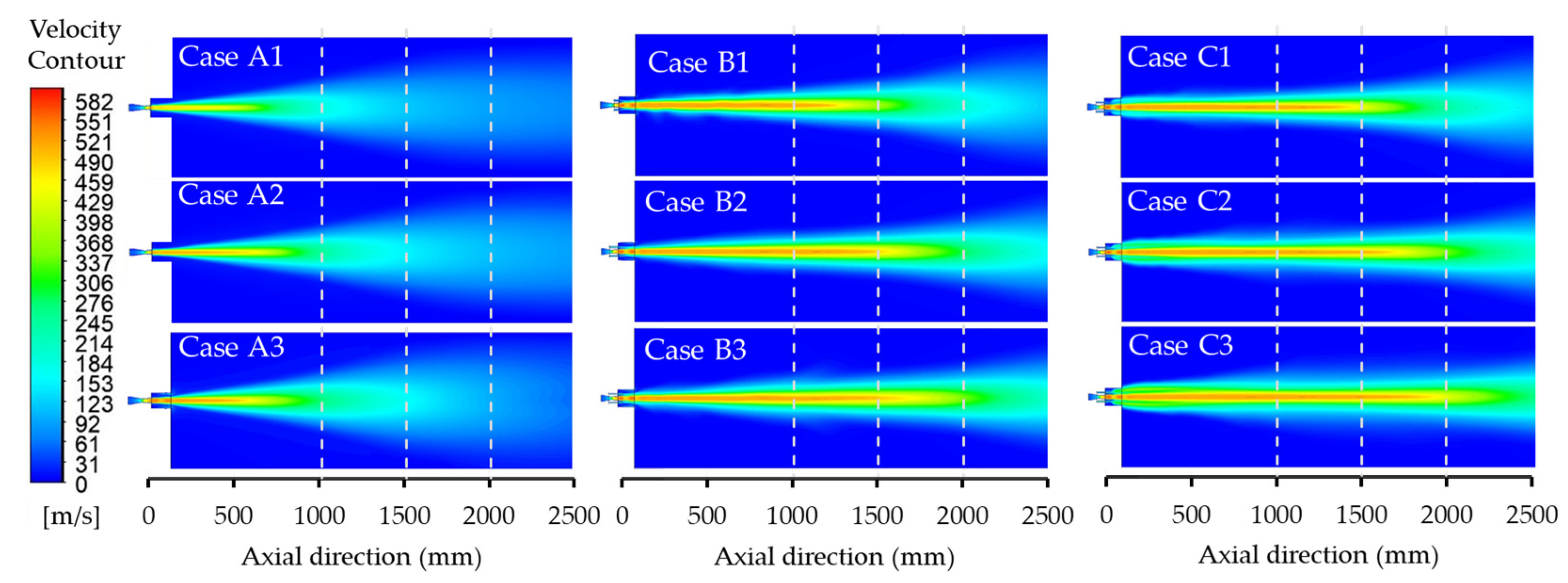
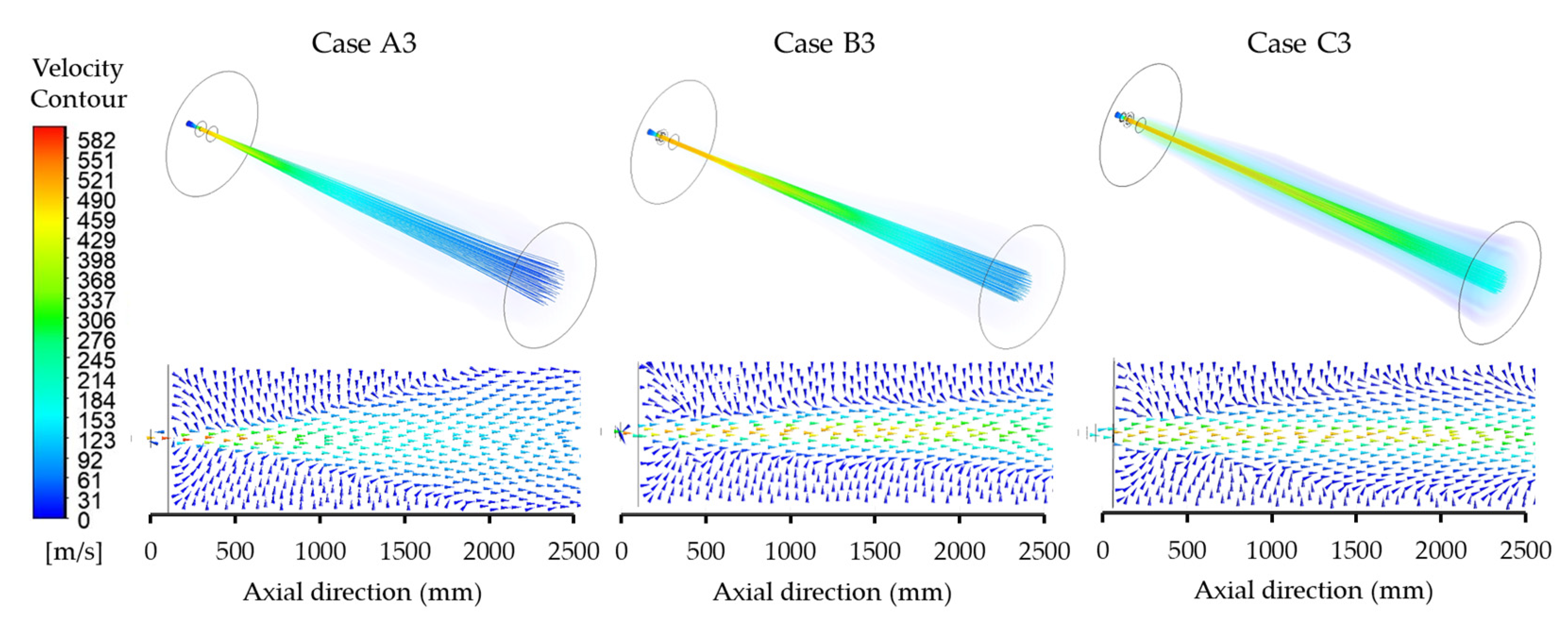
3.2. Velocity Distribution

During the refining process in the sample plant, the conventional jet is used to refine the liquid iron to molten steel. In this study, two main types of O2 injection techniques, i.e., conventional jet and coherent jet, were compared by measuring the velocity in the X-direction. Figure 11 shows the axial velocity results of a supersonic jet at the centerline. The improper velocity expansion of the supersonic jet causes the shock waves to generate at the nozzle exit. After the oscillation of the supersonic O2 jet, the axial velocity stabilizes at a distance of around 250 mm from the nozzle exit, and a potential core is generated [6]. The potential core length is defined as the maximum length of the jet core with a constant axial velocity. Typically, the Mach number of a supersonic jet in the potential core ranges from 2.0 to 2.3. In Case A1, the axial velocity is 480 m/s, and the potential core length is 300 mm. When the flow rate increased in Case A2 and Case A3, the axial velocity increased to 500 m/s and 512 m/s, respectively. The potential core lengths of the conventional jet in these cases are 400 and 480 mm, respectively. Case A3 was combined with various types of shrouding nozzles for further study to investigate the coherent jet. It was found that increasing the shrouding flow rate did not change the maximum velocity of the main O2 jet, but it could maintain the axial velocity over a longer distance than the conventional jet. For the CH4 coherent jet, the main O2 jet is combined with CH4 injection at flow rates of Cases B1, B2, and B3. The increased CH4 flow rate results in the potential axial length of the main O2 jet being 1054 mm, 1280 mm, and 1504 mm, respectively. The potential core lengths of main O2 in Cases B1, B2, and B3 are increased by 2.19, 2.67, and 3.13 times, respectively, compared to Case A3. For the CH4 + O2 coherent jet, the shrouding flame is generated from various CH4 and O2 shrouding flow rates in Cases C1, C2, and C3. As a result, the injection of O2 mixed with CH4 from the shrouding nozzle promotes the efficiency of the shield flame. The potential core lengths of the main O2 jet reach 1255 mm, 1470 mm, and 1670 mm, which increased by 2.61, 3.06, and 3.48 times longer than the conventional jet (Case A3), respectively.
Figure 12 presents the velocity in the longitudinal section plane of the supersonic jet. When comparing the injection of a coherent jet with an O2 shrouding nozzle (Case C) and without it (Case B), Case C provides a potential core length that is approximately 1.1 times longer than Case B. The combustion flame of the shrouding nozzle plays a significant role in establishing a low density surrounding hot gas around the main O2 jet, which reduces the momentum exchange at the boundary between the main O2 jet and the external environment, resulting in a longer potential core length compared to the conventional jet.
Figure 13 shows the streamlines and velocity flow fields of both conventional jets and coherent jets in the 3D and 2D cross-sectional planes. The streamline in three types of injection is created around 500 samplings. The streamline particles enter the inlet and exit at the downstream outlet. The arrowheads and colors indicate the direction and magnitude of the flow velocity. In the conventional jet (Case A), the O2 jet passes from the nozzle exit to the ambient with a wide radial distribution and a decrease in axial velocity. On the other hand, for the coherent jets (Cases B and C), the shrouding flame acts as a shield for the potential core. The central axis exhibits a longer constant velocity, and the axial velocity dispersion is narrower compared with that of the conventional jet.

3.3. Temperature Distribution

According to the EAF atmosphere in the refining process, a temperature of 1700 K was set as an initial condition to study the potential of O2 jet injection in the high ambient temperature condition. Figure 14 shows the axial static temperature profile of the main O2 jet at the centerline with various flow rates of the shrouding nozzle. The temperature core length is defined as the distance from the nozzle exit where the temperature remains constant. For conventional jets, the main O2 jet has a high rate of heat exchange with stationary gases at ambient temperature. This causes the main jet temperature to rapidly increase to ambient temperature. In both cases of coherent jets, the shrouding combustion flame generated using the gas flow from the shrouding nozzle prevents the thermal exchange of the main O2 jet with ambient temperature, which maintains temperature and prolongs the core jet. The temperature core lengths of the conventional jet in Cases A1 to A3 are 300 mm, 400 mm, and 480 mm, respectively. However, when transitioning to a CH4 coherent jet in Cases B1, B2, and B3, the temperature core lengths increase to 1054 mm, 1280 mm, and 1504 mm, respectively. A further enhancement is observed in the CH4 + O2 coherent jet in Cases C1, C2, and C3, where the temperature core lengths prolong to 1255 mm, 1470 mm, and 1670 mm, respectively. As the main O2 jet reaches the end of its potential core, it mixes with the combustion flame and absorbs thermal energy, resulting in a rapid increase in jet temperature to its maximum level and gradually transitioning towards the ambient temperature.
Figure 15 represents the static temperature distribution of the conventional jet (Case A) and coherent jets (Case B and Case C) in the longitudinal section plane under various conditions. In the presence of a high ambient temperature at 1700 K, illustrated by the green area, the main O2 jet with a temperature of 298 K is indicated by the blue area. The thermal energy of conventional jets quickly exchanges with the surrounding gas environment. As a result, the temperature core jet quickly reaches the ambient temperature. In both cases of coherent jets, the combustion flame expands after passing through the nozzle exits and prolonging in the axial directions. The combustion flame of the CH4 + O2 coherent jet in Case C form immediately at the nozzle exit, while that of the CH4 coherent jet in Case B forms at an axial distance of around 100 to 400 mm from the nozzle exit. When the combustion flame covers the main O2 jet, it acts as a barrier separating the main O2 jet from the ambient gas and generates a region of low-density hot gas surrounding the main O2 jet. Consequently, the higher the shrouding gas flow rate, the lower the heat exchange between the main O2 jet and the surroundings. In Case B, CH4 shrouding reacts with the main O2 jet and the stationary surrounding air with an enlarged combustion area. Meanwhile, in Case C, a combustion reaction occurs on both the inner and outer sides of the CH4 shrouding with O2 and provides a jet with a narrower shape of the flame and a longer distance of the main O2 jet compared with Case B. The simulation results are consistent with the experiments of Sung et al. [4], explaining that in Case C, the diffusion of the shrouding fuel gas to the surrounding air is less than that in Case B, resulting in better efficiency. Therefore, the mixing design of fuel and O2 is an important factor in the design of nozzles for proper combustion.

3.4. Dynamic Pressure

Dynamic pressure plays a crucial role in determining the shape of the impact cavity and is proportional to the kinetic energy resulting from the jet velocity. According to literature reviews [12,21,32], an increase in the dynamic pressure of the jet leads to a larger radius and greater depth of the impact cavity. Higher dynamic pressure results in a greater amount of momentum being delivered to the molten bath, thereby enhancing O2 penetration and accelerating dephosphorization and decarburization rates during the refining process. In this research study, the dynamic pressure profiles in the radial direction of an O2 jet at different axial positions: X = 1000 mm, 1500 mm, and 2000 mm, were investigated, considering the distance between the nozzle exit and the molten steel level according to the expected EAF lifetime. Similar to axial velocity results shown in Figure 10, the dynamic pressure along the axial direction remains constant throughout the potential core length distance. However, beyond the potential core region, the dynamic pressure decreases in correlation with the axial velocity. Figure 16 shows the radial distributions of dynamic pressures for conventional and coherent jets at high ambient temperatures of each position.
The conventional jet, operating at its maximum flow rate (Case A3), generates dynamic pressures of 9.8 kPa, 3.0 kPa, and 1.5 kPa at positions 1000 mm, 1500 mm, and 2000 mm, respectively. In Cases B1–B3, where a CH4 coherent jet was injected into the shrouding nozzle at different flow rates, the resulting dynamic pressures are 330 kPa, 330 kPa, and 330 kPa at position 1000 mm, and 30 kPa, 50 kPa, and 180 kPa at position 1500 mm, respectively. The dynamic pressure gradually decreases as the position increases to 2000 mm, with values of 4.6 kPa, 8.8 kPa, and 13 kPa, respectively. In the cases of CH4 + O2 coherent jet (Cases C1–C3), the dynamic pressure is 340 kPa at 1000 mm, 40 kPa, 300 kPa, and 320 kPa at 1500 mm, and 7 kPa, 15.2 kPa, and 29.6 kPa at the 2000 mm, respectively. The results indicate that the CH4 coherent jet (Case B) demonstrates superior performance compared to the conventional jet (Case A3). Additionally, the CH4 + O2 coherent jet (Case C) exhibits a larger impact cavity and experiences slower attenuation of dynamic pressure, making it advantageous for longer distances.

3.5. Species Mass Fraction

In the refining process, O2 was used to refine steel impurities. The combustion reaction between CH4 and O2 was examined in this study. The mass fraction of combustion products can be obtained from the simulation results. The primary reaction products within the combustion zone are carbon dioxide (CO2) and water (H2O). Similar to axial velocity results in Figure 11, the O2 mass fraction in the potential core length along the axial direction is 1. Beyond the potential core region, the O2 mass fraction decreases, which is equivalent to the mass fraction of O2 in the atmosphere. Figure 17 represents the radial profile of the O2 mass fraction at different axial locations. In Case B, the CH4 shrouding gas reacts with the main O2 jet and surrounding ambient gases, resulting in the formation of a combustion zone. At the axial position 1000 and 1500 mm, the combustion reaction leads to lower O2 concentrations around the main O2 jet. At the position of 2000 mm, the combustion reaction is complete, and the O2 concentration surrounding the main jet returns to levels that are higher than 0.21. In Case C, O2 enrichment is injected through the O2 shrouding nozzle to displace the surrounding ambient gases. This results in a complete combustion reaction within the shrouding flame, maintaining the main O2 jet concentration. When distance increases, the attenuation of the O2 concentration in the main jet of Case C is slower than that of Case B.

3.6. Prediction of Jet Penetration at Impact Zone

Figure 18 presents the relationship between jet conditions, average velocity, and the impacted-O2 molar flow rate (i.e., the O2 molar flow rate at the impaction zone between the O2 jet and molten steel). The results were represented by the average value in the circular cross-section planes with a radius of 100 mm at three different axial positions of 1000, 1500, and 2000 mm. In the refining process of the sample plant, the flow rate of conventional jet Case A3 was the representative parameter that was most often employed. At the nozzle-to-molten metal positions 1000 mm, 1500 mm, and 2000 mm, the average velocities in Case A3 are 170 m/s, 130 m/s, and 96 m/s, respectively. Additionally, the corresponding impacted-O2 molar flow rates at these positions are 24 mol/s, 14 mol/s, and 9 mol/s, respectively.
Furthermore, the penetration depth of the inclined jet, determined by applying the theoretical model equation described in Wu et al. research [30], is presented in Table 3. For Case A3, the penetration depth at a nozzle-to-molten metal distance of 1000 mm is 389 mm. As the distance increased to 1500 mm and 2000 mm due to refractory wear, the jet penetration depth decreased to 319 mm and 286 mm, respectively. The decrease in jet penetration depth over the EAF lifetime has an impact on various process parameters, including longer refining times and increased electrical consumption. These effects correspond with the production report of the sample steel plant illustrated in Figure 3.
To ensure consistently efficient O2 injection in the refining process of the sample steel plant, where the distance between the nozzle and molten steel bath increases from 1000 mm to 2000 mm over the lifetime of EAF due to the refractory wear, it is necessary to maintain the O2 molar flow rate and penetration depth at around 24 mol/s and 389 mm, respectively. The corresponding jet conditions that meet the requirement are as follows: Case A3 at 1000 mm, Case B1 at 1500 mm, and Cases C2 at 2000 mm, respectively.
Based on the production report from the sample steel plant, it was observed that an increase in refractory wear extended the steelmaking power-on time (Pon) by 6 min. This extension resulted in an increase in electrical consumption in the EAF steelmaking process of 2.97 USD per ton of billet (USD/t). However, if there is an improvement in the refining process, as seen in the Case of C3, leading to an increase in methane and oxygen shrouding consumption of 0.0496 kg/s and 0.198 kg/s, respectively, the cost will rise by 0.74 USD/t. Nevertheless, if it is assumed that the increased Pon from furnace wear can be reduced by 3 min, equal to a savings of 1.485 USD/t, the electricity cost, after accounting for the additional methane and oxygen shrouding, can be lowered by 0.75 USD/t.

4. Conclusions

This study investigated and optimized the energy efficiency of the EAF refining process. CFD simulation was employed to adjust the nozzle flow conditions and analyze the jet performance. Three jet injection techniques, i.e., the conventional jet, the CH4 coherent jet, and the CH4 + O2 coherent jet, were analyzed and discussed. The mass flow rate parameters, namely the main O2 jet flow rate, CH4 shrouding flow rate, and O2 shrouding flow rate, were also adjusted. The findings from this study can be summarized as follows:
(1)
The turbulence models were validated, and the results indicate that the RNG k-ε model offers the most accurate prediction for the velocity profile of the coherent jet.
(2)
The research demonstrates that energy efficiency was improved by optimizing the flow conditions of the main O2 jet and shrouding nozzles.
(3)
The utilization of a shrouding nozzle and the adjustment of its flow rate has a significant impact on the potential core length of the jet. The combustion flame of the shrouding nozzle effectively minimizes the interaction between the main O2 jet and the surrounding environment. This phenomenon contributes to maintaining the axial velocity and enhances the dynamic pressure of the main O2 jet.
(4)
The potential core length of the main O2 jet in the coherent jet was approximately 2.5 times longer than that observed in the conventional jet. Furthermore, the CH4 + O2 coherent jet with an O2 shrouding nozzle (Case C) exhibited a potential core length 1.1 times longer than the case without an O2 shrouding (Case B).
(5)
Based on the prediction calculations, it was determined that utilizing the appropriate flow conditions in coherent jet injection during the refining process, particularly at nozzle-to-steel distances greater than 1000 mm, can maintain the impacted-O2 molar flow rate for more than 23 mol/s and the penetration depth for more than 380 mm. This will lead to savings in steelmaking power-on-time and electrical consumption costs.
A recommendation for maintaining the jet penetration in the sample steel plant was given. The conventional jet (Case A3) is commonly utilized in the refining process. However, when the nozzle-to-steel distance increases from its initial level of 1000 mm to 1500 mm, it is advisable to transition to the CH4 coherent jet (Case B1). Similarly, when the nozzle-to-steel distance reaches 2000 mm, transitioning to the CH4 + O2 coherent jet (Case C2) is advised. This technique provides an alternative means of sustaining the efficiency of O2 jet injection by adapting to varying levels of molten steel within the EAF furnace and enhancing the O2 efficiency of the refining process.

Author Contributions

Conceptualization, P.T., P.K., Y.P., and S.O.; methodology, P.T., P.K., Y.P., and S.O.; software, P.T., P.K., Y.P., and S.O.; validation, P.T., P.K., Y.P., and S.O.; formal analysis, P.T., P.K., Y.P., and S.O.; investigation, P.T., P.K., Y.P., and S.O.; resources, P.T. and P.K.; data curation, P.T., and P.K.; writing—original draft preparation, P.T., P.K., and S.O.; writing—review and editing, P.T., P.K., Y.P., and S.O.; visualization, P.T., P.K., and S.O.; supervision, P.K., Y.P., and S.O.; project administration, P.K., and S.O.; funding acquisition, P.K., and S.O. All authors have read and agreed to the published version of the manuscript.

Funding

This research was funded by NSTDA-KMUTNB Collaborative Research and Development of High-Quality Post Graduate Scholarship with Contract No. Grad015/2563; and National Science, Research and Innovation Fund (NSRF), and King Mongkut’s University of Technology North Bangkok with Contract no. KMUTNB-FF-66-55.

Data Availability Statement

Not applicable.

Conflicts of Interest

The authors declare no conflict of interest.

References

  1. Tang, G.; Chen, Y.; Silaen, A.K.; Krotov, Y.; Riley, M.F.; Zhou, C.Q. Effects of Fuel Input on Coherent Jet Length at Various Ambient Temperatures. Appl. Therm. Eng. 2019, 153, 513–523. [Google Scholar] [CrossRef]
  2. He, C.; Zhu, R.; Dong, K.; Qiu, Y.; Sun, K. Modeling of an Impinging Oxygen Jet on Molten Bath Surface in 150 t EAF. J. Iron Steel Res. Int. 2011, 18, 13–20. [Google Scholar] [CrossRef]
  3. Lee, B.; Sohn, I. Review of Innovative Energy Savings Technology for the Electric Arc Furnace. JOM 2014, 66, 1581–1594. [Google Scholar] [CrossRef]
  4. Sung, Y.; Lee, S.; Han, K.; Koo, J.; Lee, S.; Jang, D.; Oh, C.; Jang, B. Improvement of Energy Efficiency and Productivity in an Electric Arc Furnace through the Modification of Side-Wall Injector Systems. Processes 2020, 8, 1202. [Google Scholar] [CrossRef]
  5. Nardin, G.; Meneghetti, A.; Dal Magro, F.; Benedetti, N. PCM-Based Energy Recovery from Electric Arc Furnaces. Appl. Energy 2014, 136, 947–955. [Google Scholar] [CrossRef]
  6. Memoli, F.; Mapelli, C.; Ravanelli, P.; Corbella, M. Simulation of Oxygen Penetration and Decarburisation in EAF Using Supersonic Injection System. ISIJ Int. 2004, 44, 1342–1349. [Google Scholar] [CrossRef]
  7. Liu, F.; Zhu, R.; Dong, K.; Hu, S. Flow Field Characteristics of Coherent Jet with Preheating Oxygen under Various Ambient Temperatures. ISIJ Int. 2016, 56, 1519–1528. [Google Scholar] [CrossRef]
  8. Tolazzi, D.; Candusso, C.; Marcuzzi, S. New Developments and Operational Results in the Use of Fixed Side-Wall Injectors in the Electric Arc Furnaces. In Proceedings of the 47th Steelmaking Seminar-International, Rio de Janeiro, Brazil, 26–30 September 2016; pp. 727–740. [Google Scholar] [CrossRef]
  9. Yang, L.; Hu, H.; Yang, Z.; Xue, B.; Guo, Y.; Wang, S. A Review on Bath Fluid Flow Stirring Technologies in EAF Steelmaking. J. Iron Steel Res. Int. 2021, 28, 1341–1351. [Google Scholar] [CrossRef]
  10. Mottahedi, A.A.; Amani, S. Using Oxygen Reaction as Electricity Saving in Electric Arc Furnace Steel Making. Int. J. ChemTech Res. 2009, 1, 62–70. [Google Scholar]
  11. Wei, G.; Zhu, R.; Cheng, T.; Dong, K.; Liu, R. Modelling on the Penetration Depth of the Coherent Supersonic Jet in EAF Steelmaking. Ironmak. Steelmak. 2018, 45, 828–838. [Google Scholar] [CrossRef]
  12. Liu, F.; Zhu, R.; Wei, G.; Fan, S. Effect of Lance Structure on Behavior of Coherent Jet in EAF Steelmaking Process. Materials 2020, 13, 1043. [Google Scholar] [CrossRef] [PubMed]
  13. Liu, F.; Sun, D.; Zhu, R.; Fan, S. Behaviors of Coherent Flow Field with Various Shrouding Nozzles Arrangement. ISIJ Int. 2018, 58, 496–504. [Google Scholar] [CrossRef]
  14. Alam, M.; Naser, J.; Brooks, G. Computational Fluid Dynamics Simulation of Supersonic Oxygen Jet Behavior at Steelmaking Temperature. Metall. Mater. Trans. B 2010, 41, 636–645. [Google Scholar] [CrossRef]
  15. Matsuura, H.; Fruehan, R.J. Slag Foaming in an Electric Arc Furnace. ISIJ Int. 2009, 49, 1530–1535. [Google Scholar] [CrossRef]
  16. Liu, F.; Sun, D.; Zhu, R.; Su, R.; Wang, X. Effect of Shrouding CH4 Flow Rate on Flow Field and Stirring Ability of Coherent Jet in Steelmaking Process. SpringerPlus 2016, 5, 1613. [Google Scholar] [CrossRef]
  17. Zhao, F.; Zhu, R.; Wang, W. Characteristics of the Supersonic Combustion Coherent Jet for Electric Arc Furnace Steelmaking. Materials 2019, 12, 3504. [Google Scholar] [CrossRef]
  18. Zhao, F.; Zhu, R.; Wang, W. Characteristics of a Coherent Jet Enshrouded in a Supersonic Fuel Gas. Int. J. Miner. Metall. Mater. 2020, 27, 173–180. [Google Scholar] [CrossRef]
  19. Zhao, F.; Di, T.; Zhu, R.; Wang, W. Supersonic Shrouding Methane Mixtures for Supersonic Combustion Coherent Jets. Metals 2023, 13, 123. [Google Scholar] [CrossRef]
  20. Zhao, F.; Sun, D.; Zhu, R.; Yang, L. Effect of Shrouding Gas Parameters on Characteristics of Supersonic Coherent Jet. Metall. Mater. Trans. B 2017, 48, 1807–1816. [Google Scholar] [CrossRef]
  21. Liu, F.; Sun, D.; Zhu, R.; Li, Y. Effect of Shrouding Gas Temperature on Characteristics of a Supersonic Jet Flow Field with a Shrouding Laval Nozzle Structure. Metall. Mater. Trans. B 2018, 49, 2050–2062. [Google Scholar] [CrossRef]
  22. Hu, S.; Zhu, R.; Dong, K.; Liu, R. Numerical Simulation and Industrial Experimental Research on the Coherent Jet with “CH4 + N2” Mixed Fuel Gas. Metall. Mater. Trans. B 2018, 49, 2584–2598. [Google Scholar] [CrossRef]
  23. Megahed, G.M.; Fathy, A.M.; Morsy, M.A.; Abdelaziz, E.A. Improving EAF Performance by Chemical Energy Optimisation at Ezz Flat Steel. Ironmak. Steelmak. 2010, 37, 445–451. [Google Scholar] [CrossRef]
  24. Memoli, F.; Mapelli, C.; Ravanelli, P.; Corbella, M. Evaluation of the Energy Developed by a Multipoint Side-Wall Burner-Injection System during the Refining Period in a EAF. ISIJ Int. 2004, 44, 1511–1516. [Google Scholar] [CrossRef]
  25. Alam, M.; Naser, J.; Brooks, G.; Fontana, A. Computational Fluid Dynamics Modeling of Supersonic Coherent Jets for Electric Arc Furnace Steelmaking Process. Metall. Mater. Trans. B 2010, 41, 1354–1367. [Google Scholar] [CrossRef]
  26. Chen, Y.; Silaen, A.K.; Zhou, C.Q. 3D Integrated Modeling of Supersonic Coherent Jet Penetration and Decarburization in EAF Refining Process. Processes 2020, 8, 700. [Google Scholar] [CrossRef]
  27. Liu, F.; Zhu, R.; Dong, K.; Hu, S. Effect of Ambient and Oxygen Temperature on Flow Field Characteristics of Coherent Jet. Metall. Mater. Trans. B 2016, 47, 228–243. [Google Scholar] [CrossRef]
  28. Cheng, T.; Zhu, R.; Dong, K. Effect of Methane-Hydrogen Mixtures on Flow and Combustion of Coherent Jets. J. Iron Steel Res. Int. 2017, 24, 1143–1151. [Google Scholar] [CrossRef]
  29. Tang, G.; Chen, Y.; Silaen, A.K.; Krotov, Y.; Riley, M.F.; Zhou, C.Q. Investigation on Coherent Jet Potential Core Length in an Electric Arc Furnace. Steel Res. Int. 2019, 90, 1800381. [Google Scholar] [CrossRef]
  30. Wu, X.-T.; Zhu, R.; Wei, G.-S.; Dong, K. Influence of Lance Height and Angle on the Penetration Depth of Inclined Coherent and Conventional Supersonic Jets in Electric Arc Furnace Steelmaking. J. Min. Metall. Sect. B Metall. 2020, 56, 307–319. [Google Scholar] [CrossRef]
  31. Yao, L.; Zhu, R.; Tang, Y.; Wei, G.; Dong, K. Effect of Furnace Gas Composition on Characteristics of Supersonic Oxygen Jets in the Converter Steelmaking Process. Materials 2020, 13, 3353. [Google Scholar] [CrossRef]
  32. Liu, F.; Sun, D.; Zhu, R.; Li, Y. Characteristics of Flow Field for Supersonic Oxygen Multijets with Various Laval Nozzle Structures. Metall. Mater. Trans. B 2019, 50, 2362–2376. [Google Scholar] [CrossRef]
  33. Tang, G.; Chen, Y.; Silaen, A.K.; Wang, T.; Zhou, C.Q. Investigation of Supersonic Oxygen Jet Potential Core Length at Various Ambient Temperatures. JOM 2019, 71, 633–643. [Google Scholar] [CrossRef]
  34. Zhang, B.; Liu, F.; Zhu, R. The Behavior of Supersonic Jets Generated by Combination Gas in the Steelmaking Process. Materials 2021, 14, 5034. [Google Scholar] [CrossRef] [PubMed]
  35. Allemand, B.; Bruchet, P.; Champinot, C.; Melen, S.; Porzucek, F. Theoretical and Experimental Study of Supersonic Oxygen Jets. Ind. Appl. EAF. Rev. Met. Paris 2001, 98, 571–587. [Google Scholar] [CrossRef]
  36. Zhao, F.; Liu, F.; Sun, D.; Zhu, R.; Dong, K. Behaviors of Supersonic Oxygen Multi-Jets with Various Preheating Temperatures. Metall. Mater. Trans. B 2021, 52, 2626–2641. [Google Scholar] [CrossRef]
  37. Li, X.; Wei, G.; Zhu, R.; Tian, B.; Zhao, R.; Lan, X. Study on the Characteristics of Coherent Supersonic Jet with Superheated Steam. Metals 2022, 12, 835. [Google Scholar] [CrossRef]
  38. Wei, G.; Zhu, R.; Wu, X.; Yang, L.; Dong, K.; Cheng, T.; Tang, T. Study on the Fluid Flow Characteristics of Coherent Jets with CO2 and O2 Mixed Injection in Electric Arc Furnace Steelmaking Processes. Metall. Mater. Trans. B 2018, 49, 1405–1420. [Google Scholar] [CrossRef]
  39. Chen, Y.; Luo, Q.; Ryan, S.; Busa, N.; Silaen, A.K.; Zhou, C.Q. Effect of Coherent Jet Burner on Scrap Melting in Electric Arc Furnace. Appl. Therm. Eng. 2022, 212, 118596. [Google Scholar] [CrossRef]
  40. Liu, F.; Sun, D.; Zhu, R.; Hu, S. Exploring the Behavior of a Coherent Flow Field Produced by a Shrouding Laval Nozzle Structure. ISIJ Int. 2020, 60, 682–690. [Google Scholar] [CrossRef]
  41. Liu, F.; Sun, D.; Zhu, R.; Hu, S. Effect of Shrouding Mach Number and Ambient Temperature on the Flow Field of Coherent Jet with Shrouding Laval Nozzle Structure. Can. Metall. Q. 2019, 58, 96–106. [Google Scholar] [CrossRef]
Figure 1. (a) The position of O2 jets inside the EAF (top and cross-section view); (b) One of the O2 nozzles.
Metals 13 01507 g001
Figure 2. Molten steel level of (a) new furnace and (b) after 600 heats.
Metals 13 01507 g002
Figure 3. The O2 consumption and electrical consumption at different EAF lifetimes.
Metals 13 01507 g003
Figure 4. Longitudinal cross-section and front view of the supersonic jet nozzle.
Metals 13 01507 g004
Figure 5. Front view of a main O2 jet inlet and shrouding nozzle inlets under various conditions (a) Conventional jet (Cases A1–A3), (b) CH4 coherent jet (Cases B1–B3), and (c) CH4 + O2 coherent jet (Cases C1–C3).
Metals 13 01507 g005
Figure 6. The schematic of the domain and boundary conditions.
Metals 13 01507 g006
Figure 7. (a) The computational mesh of the domain and (b) the cross-sectional plane.
Metals 13 01507 g007
Figure 8. Mesh Independency: (a) Axial velocity profile of coherent jet ix mesh levels, and (b) velocity magnitude at positions of 1750 mm and 2000 mm from the nozzle exit.
Metals 13 01507 g008
Figure 9. Validation of turbulence model on coherent jet axial velocity profile at high ambient temperature. Data from [13].
Metals 13 01507 g009
Figure 10. Validation axial velocity results of (a) conventional and (b) coherent jet at high ambient temperature (c) simulation result of temperature distributions of the coherent jet at high ambient temperature. Data from [12,13].
Metals 13 01507 g010
Figure 11. Axial velocity distributions of the conventional jet (Case A), CH4 coherent jet (Case B), and CH4 + O2 coherent jet (Case C) at the centerline.
Metals 13 01507 g011
Figure 12. Supersonic jet velocity contour of Case 1–9 on longitudinal section with at high ambient temperature.
Metals 13 01507 g012
Figure 13. Velocity of 3D flow structure and the 2D cross-sectional plane of the conventional jet (Case A3), CH4 coherent jet (Case B3), and CH4 + O2 coherent jet (Case C3).
Metals 13 01507 g013
Figure 14. Axial static temperature of the conventional jet (Case A), CH4 coherent jet (Case B), and CH4 + O2 coherent jet (Case C) at the centerline.
Metals 13 01507 g014
Figure 15. Temperature distribution contour of Case 1–9 on the longitudinal section at high ambient temperature.
Metals 13 01507 g015
Figure 16. Dynamic pressure distribution in radius direction at axial position 1000 mm, 1500 mm, and 2000 mm.
Metals 13 01507 g016
Figure 17. O2 mass fraction distribution in radius direction at axial position 1000 mm, 1500 mm, and 2000 mm.
Metals 13 01507 g017
Figure 18. The relationship between average velocity, O2 molar flow rate, and jet conditions with three different distances.
Metals 13 01507 g018
Table 1. The O2 lance techniques were studied in previous research.
ReferencesConventional Jet
(No Shrouding)
CH4
Coherent Jet
CH4 + O2
Coherent Jet
Other
[1,7,11,12,16,22,25,26,27,28,29,30]
[2,6,14,23,24,31,32,33,34,35,36]
[4]
[13,37,38,39]
[17,18]
[19]
[20,21,40,41]
Table 2. The parameters of mass flow rate for the CFD simulation.
CaseMain O2 Jet
Flow Rate (kg/s)
CH4 Shrouding
Flow Rate (kg/s)
O2 Shrouding
Flow Rate (kg/s)
Conventional jetA10.476
A20.635
A30.715
CH4
coherent jet
B10.7150.0297
B20.7150.0496
B30.7150.0695
CH4 + O2
coherent jet
C10.7150.02970.118
C20.7150.04960.198
C30.7150.06950.277
Table 3. Prediction of penetration depth in the molten steel at different injection types.
Nozzle-to-Molten Steel Distance
(mm)
Penetration Depth for Each Injection Condition
Conventional Jet CH4 Coherent Jet CH4 + O2 Coherent Jet
A1 A2 A3 B1 B2 B3 C1 C2 C3
1000349373389718712720716726728
1500295310319416488517458648666
2000268279286334365378350388427
Disclaimer/Publisher’s Note: The statements, opinions and data contained in all publications are solely those of the individual author(s) and contributor(s) and not of MDPI and/or the editor(s). MDPI and/or the editor(s) disclaim responsibility for any injury to people or property resulting from any ideas, methods, instructions or products referred to in the content.

