Article

Mechanism and Control Scheme of Central Defects in Cross Wedge Rolling of Railway Vehicle Axles

1
School of Mechanical Engineering, University of Science and Technology Beijing, Beijing 100083, China
2
Beijing Laboratory of Metallic Materials and Processing for Modern Transportation, Beijing 100083, China
*
Author to whom correspondence should be addressed.
Metals 2023, 13(7), 1309; https://doi.org/10.3390/met13071309
Submission received: 20 June 2023 / Revised: 15 July 2023 / Accepted: 16 July 2023 / Published: 21 July 2023
(This article belongs to the Special Issue Rolling Process of Metallic Materials)

Abstract

:
Faced with a great demand for railway axles, the cross wedge rolling (CWR) process has the advantages of high efficiency and material saving, and good forming quality of axles is significant for railway transportation safety. The stress inside the railway axle of CWR was analyzed by the finite element method. It was found that the center of the rolled piece is subjected to tensile stress in transverse and axial directions and compressive stress in radial direction, making it more prone to defects. By simulating the evolution of micro voids in the center of the CWR piece, it was found that the presence of voids makes the strain around them significantly large and concentrated and the material between the voids deforms intensely. When voids expand relative to the rolled piece and the internal necking between voids is significant, void coalescence is easy to occur, and central defects are formed. The influence of process parameters on void evolution was analyzed. The scheme of detaching die was proposed to avoid central defects of the CWR piece and the optimal parameter conditions of CWR of railway axles were determined, which proved that the quality of railway axles formed with optimized parameters meets the technical requirements of railway vehicle axles.

1. Introduction

The railway axle is the key component for railway vehicles to transmit movement and power, and it is also a large-scale product of mass production. For example, the annual production of railway axles is more than 500 thousand in the world [1]. Currently, the main techniques used to manufacture axles are open die forging and radial forging [2], and the forming accuracy, production efficiency, and material utilization of railway axles are expected to increase. CWR is an advanced forming process for shaft parts, it is particularly suitable for mass production of rotating shaft parts, such as railway axles. Li et al. [3] analyzed the metal flow and stress and strain distribution in the process of multi-wedge cross wedge rolling (MCWR) of railway axles by using finite element software, verifying the feasibility of MCWR of railway axles. Jiang et al. [4] simulated the stress, strain, and temperature distribution in the process of CWR of thick-walled hollow axles by using finite element software, indicating that it is feasible to form thick-walled hollow axles by CWR. Based on the continuous damage theory, Huo et al. [5,6] established a constitutive model coupling microstructure and ductile damage in the process of CWR of high-speed railway axle and predicted the grain size and ductile damage of the material during CWR, thereby optimizing the process parameters. Pater et al. [7,8] analyzed the distribution of temperature, damage, effective strain, force, and torque during the CWR of railway axles by finite element simulation, found that it is feasible to produce solid railway axles, and proposed that the use of tools with a convex forming surface can effectively reduce rolling force and energy consumption. Tomasz et al. [9] conducted numerical simulations of railway axles in traditional CWR and MCWR, respectively, and found that the Cockcroft–Latham ductile fracture criterion cannot accurately predict material fracture, while the fracture criterion proposed by Ayada et al. can better predict the fracture of railway axles in the process of CWR. Jia et al. [10] established the ductile damage model for 40CrNiMo steel and simulated the distribution characteristics of the ductile damage as well as the evolution of the stress state and the Z parameter when 40CrNiMo steel was rolled into the high-speed rail axle at high temperature. It was found that the damage could be decreased by reducing the forming angle, increasing the stretching angle, maintaining the area reduction at 35%, machining the hollow axle, and setting the rolling speed and temperature at 8 r/min and 1273~1323 K. Xu et al. [11] used a fast forging machine to forge the square billet into a round shaft billet first, and then rolled the round billet into an axle by CWR. The microstructure and mechanical properties of the axle met the standard requirements. Gao et al. [12] carried out a dynamic simulation on the CWR process of LZ50 axle steel and analyzed the stress, strain, and temperature fields of the axle steel during the forming process. The results show that the plastic deformation of the metal becomes more and more obvious with the increase in rolling depth. When the sizing zone is reached, the temperature distribution on the surface and inside of the rolled piece is relatively uniform. Huo et al. [13] developed the microstructure evolution model of 40CrNiMo steel, simulated the microstructure evolution during the CWR process of high-speed railway axle, and analyzed the effects of rolling temperature, rolling speed, and initial grain sizes on the microstructure distribution of 40CrNiMo steel after hot CWR.
The railway axle bears various complex loads during operation, so ensuring the forming quality of the axle is the prerequisite for its safe use. For CWR process, avoiding central defects in rolled parts has always been one of the major concerns. Therefore, it is necessary to avoid the central defects of the axle strictly so as to apply the CWR technology to the production of railway axles. Dong et al. [14] established a three-dimensional finite element model of CWR. By analyzing the stress and strain characteristics of the workpiece, it was found that internal damage occurs when the first principal stress in the center of the workpiece exceeds the yield stress. Li et al. [15] determined and discussed the formation and growth morphology of micro voids during CWR based on the experimental results and defined a dimensionless deformation coefficient to predict the possibility of void formation. Li and Lovell [16] found that effective plastic strain is the best criterion for predicting internal damage based on numerical simulation results. Pater et al. [17] found that due to the positive mean stress, the crack was most likely to occur in the center of the workpiece through the numerical analysis of CWR of the ball pin. Wang et al. [18] studied the stress and strain distribution and alternating frequency at the center of cross wedge rolled parts under different stretching angles through finite element simulation and revealed the influence of the stretching angle on central defects through experiments. Kache et al. [19] applied CWR at warm temperatures and found that the process parameters were the main factor of the central cavity rather than the value of temperature. Zhou et al. [20] studied the variation of the maximum principal stress at the center point of the workpiece during CWR and optimized the die parameters. The results showed that under the conditions of the forming angle α = 30°, stretching zone β = 8°, area reduction Ψ1 = 48.6%, Ψ2 = 53.3%, the workpiece with good central quality can be obtained. Wang et al. [21] studied the effect of cooling conditions on central deformation of the workpiece and die wear. The information on central deformation of the workpiece and die wear before and after cooling were compared and analyzed. The results show that the quality of the workpiece and the lifespan of the die life can be improved by cooling the workpiece with cooling water. Huang et al. [22] studied the influence of wedge-tip fillets on the central defects in CWR by finite element simulation. It was found that as the wedge-tip fillet increased, the transverse and shear stresses in the center of the rolled part increased, and the possibility of central defects increased. Based on Parity Wedge, Shu et al. [23] predicted the central defect position of asymmetric axial parts during CWR and systematically studied the influence of process parameters on workpiece quality. Yang et al. [24] observed the evolution of micro voids during CWR by SEM and found that the alternating shear deformation and relative tensile deformation were the main reasons for the central defects of the rolled part and studied the influence of process parameters on the central damage. Zhou et al. [25] conducted a large number of CWR experiments using model materials, proposed that the first principal stress and the maximum shear stress were the main factors affecting central cracking, and established the damage criterion. Zhou and Shao et al. [26] studied and compared the chemical compositions, phases, grains, and inclusions of two kinds of 20NiCr3H billet. It was found that under the temperature of CWR, due to the different thermal expansion coefficients and elasticity of steel matrix and inclusions, micro voids or cracks are generated around the inclusions, which is the main reason for the central cracking of rolled parts. Zhou et al. [27,28] used model material to simulate the material flow and internal fracture behavior in the CWR workpiece, determined that the maximum shear stress is the dominant factor of the central damage, and established a damage model considering the joint influence of the maximum shear stress and the first principal stress. Shi et al. [29] found that the volume of central defects during CWR TC4 Aeroengine blades is closely related to the initial rolling temperature of the billet. When the rolling temperature of TC4 billet is higher than 850 °C, the target rolled parts without central defects can be obtained.
To study the mechanism of central defects of the railway axle formed by CWR and improve the quality of the rolled pieces, the stress variation of the rolled piece is analyzed by combining finite element simulation and experiments. By presetting micro voids in the CWR model, the deformation of internal voids during CWR and the influence of process parameters on void deformation are analyzed. The scheme of using the after-rolling detaching die is proposed to avoid central defects, and the optimal parameters of CWR of the axle were determined.

2. Research Method of Central Defects in CWR the Railway Axle

Figure 1 shows the railway axle formed by CWR. The area reduction of the axle body (diameter D1 part) is about 30%. Due to the small area reduction and long axial size, if the compressed metal cannot achieve sufficient axial flow during CWR, the possibility of central damage is high. The area reduction of the axle neck (diameter D2 part) is 50~60%, which is easy to form without central damage. In general, the diameter of the wheel seat (D0) is 180~250 mm, and the reduction ratio of 1:5 CWR of the axle body is adapted to study the central defects of the railway axle formed by CWR and the optimal process parameters of the die at a lower cost.
In a previous study by Sun et al. [30], it was found that there are non-metallic inclusions exist in metal materials. The non-metallic inclusions are broken or debonded from the matrix to form micro voids because of the different deformation degrees of the inclusions and steel matrix. These micro voids become the nucleation sites for micro damage. Figure 2 shows the micro voids and their evolution in the center of the rolled piece of 45 steel with non-metallic inclusions after CWR. When the process parameters are inappropriate, micro voids will expand and coalesce under complex stress and eventually develop into significant micro damage or even macro damage, as shown in Figure 2a–c. When the process parameters are good, even if there are micro voids in the center of the rolled piece, the number is very small. The distance between micro voids is far from coalescence and there is no macroscopic damage, as shown in Figure 2d. The evolution trend of micro voids in the center of rolled parts determines whether there will be macro damage. Therefore, it is necessary to study the evolution of micro voids in the center during CWR and optimize process parameters to improve the quality of the rolled piece.

3. FEM Analysis of CWR of the Railway Axle

3.1. Finite Element Model

The finite element model of CWR of the railway axle is established by Deform V11.0 software (SFTC, Columbus, OH, USA), as shown in Figure 3. There are top and bottom dies, workpiece, and guide plates in this geometric model. The workpiece material is LZ50 axle steel. The workpiece formed by CWR has significant plastic deformation and negligible elastic deformation and can be regarded as a plastic body. The dies and guide plates are defined as rigid bodies because of negligible elastic and plastic deformation. The friction between the dies and workpiece is defined as the shear friction, which is suitable for bulk formation. To save the calculation time and increase the number of grids, 1/2 of the model is used for simulation. Tetrahedron is used to mesh the workpiece. The minimum element size is 1.3 mm, and the size ratio is 2. Local mesh refinement is carried out on the workpiece, and the standard of mesh redivision is 0.5. The simulation parameters are listed in Table 1.

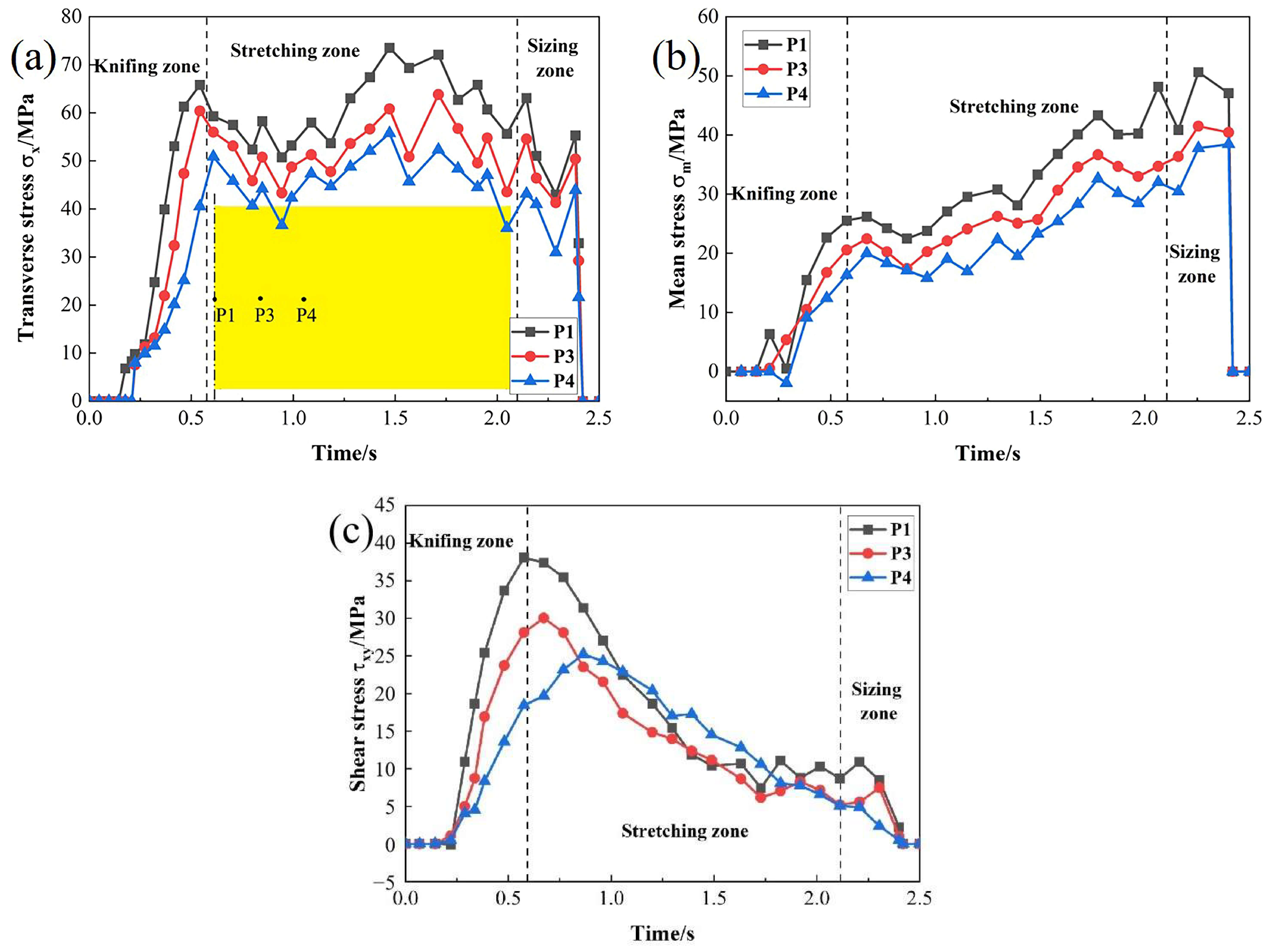
3.2. Analysis of Internal Stress of CWR Pieces

The central defects of CWR are closely related to the stress state in the workpiece. A group of typical working conditions (forming angle α = 15°, stretching angle β = 7.5°, area reduction ψ = 30%) is selected for point tracking processing to analyze the stress state inside the rolled piece.
Figure 4 shows the variation of stress in the three directions and mean stress of characteristic points on the axial symmetry plane. It can be seen from Figure 4a–c that in the whole CWR process, the central point P1 is subjected to tensile stress in both transverse and axial directions, while compressive stress in the radial direction. With the rolling progress, the tensile stress value always maintains a high level. The transverse stress, radial stress, and axial stress of P2 (near the surface) fluctuate within a certain range and are mainly compressive stress. Overall, the closer to the center, the greater the tensile stress and the smaller the compressive stress on the cross-section. It can be seen from Figure 4d that the mean stress of P1 is always positive and steadily increases during CWR, which is in a state of negative hydrostatic pressure. The mean stress of P2 fluctuates between positive and negative, which is in a state of positive hydrostatic pressure dominated by compressive stress. In addition, shear stress will be generated in the rolled piece during CWR, as shown in Figure 4e. The shear stress of P1 increases suddenly in the knifing zone and early stage of the stretching zone, mainly because the radial flow of the metal is blocked under the pressure of dies in this stage, the transverse flow of some metal causes the ellipticity of the cross-section, resulting in significant shear stress at the center. With the gradual roundness in the later stage, the shear stress gradually decreases and stabilizes at around 5 MPa. The shear stress of P2 fluctuates within a certain range.
In summary, the center on the cross-section of the rolled piece is subjected to tensile stress in two directions and compressive stress in one direction, making it more prone to defects. The position near the surface of the rolled piece is subjected to compressive stress in three directions, which can inhibit the generation of defects and promote microcrack welding. During the rolling process, the transverse tensile stress in the center of the rolled piece is the largest. Large transverse tensile stress can easily make the micro voids in the center expand into the macro voids, resulting in central defects. In addition, the mean stress in the center is always positive, which reduces the material plasticity and makes it easier to fracture. The shear stress of cross-section will cause shear deformation, which will cause lattice distortion of the metal at the center of the rolled piece, resulting in central defects.
Through the above analysis, it was found that the main factors affecting the central defects are transverse tensile stress, mean stress, and shear stress. The variation of three types of stress of characteristic points on the longitudinal section is shown in Figure 5. Although the transverse stress and mean stress at different axial positions of the rolled piece are tensile stress, the farther away from the center, the smaller the transverse stress and mean stress and the shorter the action time. In addition, the farther away from the center axially, the smaller the shear stress and there is a delay in reaching the peak stress. Therefore, on the longitudinal section of the rolled piece, the farther away from the center, the more difficult it is to produce defects.

3.3. Analysis of Evolution of Void Defects in the Center of CWR Piece

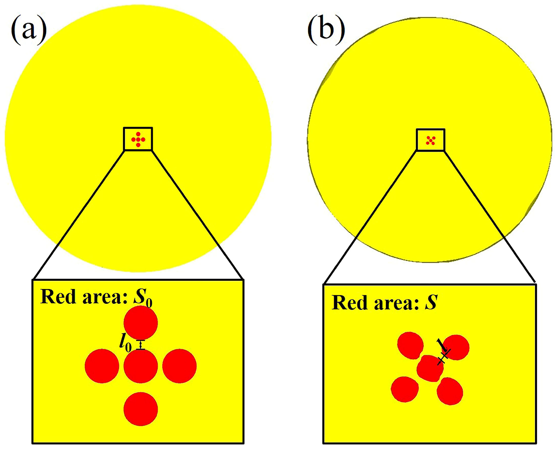
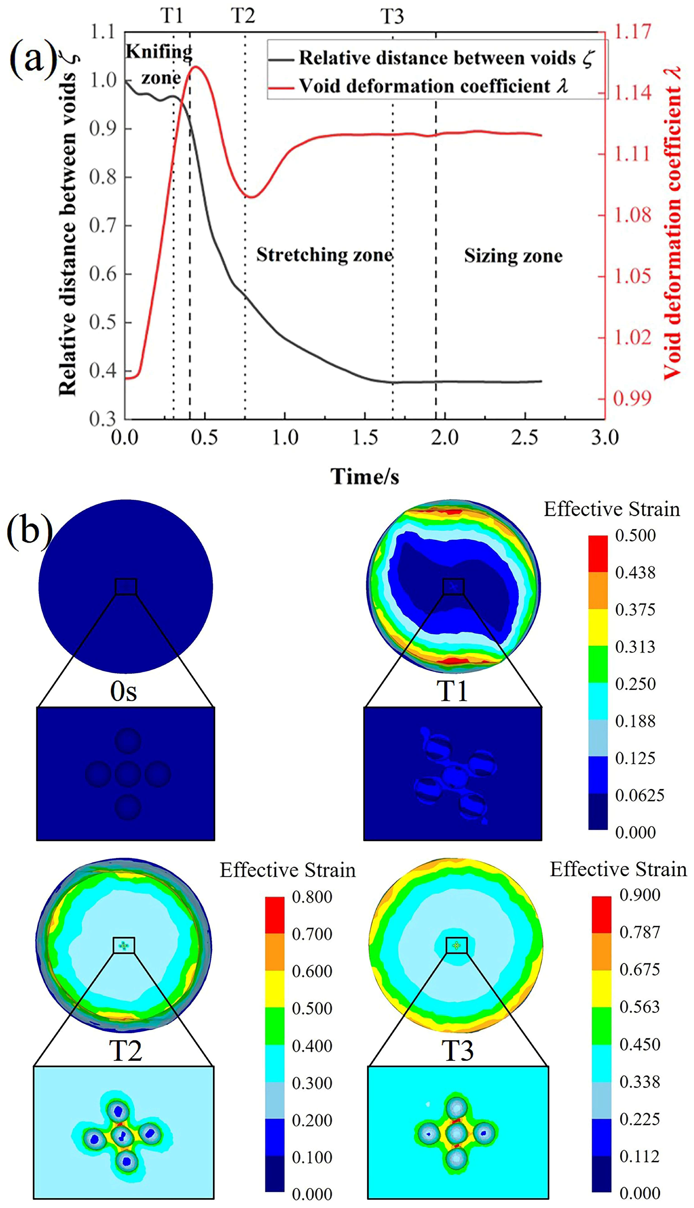
3.3.1. Void Deformation Behavior

Five voids with a diameter of 0.6 mm are preset in the center of the axial symmetry plane of the rolled piece for finite element simulation to study the deformation behavior of voids in the CWR piece. The distribution of voids is shown in Figure 6a. One of the voids is set in the center of the axial symmetry plane. The top and bottom voids are 0.75 mm away from the center, and the left and right voids are 0.65 mm away from the center.
During CWR, the cross-section area of the workpiece gradually decreases under the radial compression of the dies. Assuming uniform deformation of the workpiece, the voids will become uniformly smaller with the radial compression of the workpiece. When the area reduction of the rolled piece is ψ, the area of voids on the axial symmetry plane decreases to 1 − ψ of the original area. When the relative area of the voids is larger than 1 − ψ, it indicates that the voids have relative expansion during CWR. Conversely, the voids are relatively smaller. Therefore, the void deformation coefficient λ = S S 0 1 ψ is used to reflect the void deformation behavior, where S is the area of voids after CWR and S0 is the initial area of voids. When λ > 1, it indicates that the voids expand relative to the workpiece. When λ < 1, the voids are smaller relative to the workpiece.
Besides void volume changes, the distance between voids will also change obviously during CWR. The relative distance between voids ζ = l l 0 1 ψ is used to reflect the change in the distance between voids during CWR, where l is the distance between voids after deformation and l0 is the initial distance between voids. When ζ > 1, the distance between voids increases relative to the deformation of the workpiece, making it difficult to coalesce. When ζ < 1, the distance between voids decreases, making it easy for voids to coalesce.
By measuring the initial area of voids S0 and the initial distance between voids l0 before CWR (Figure 6a) and the area of voids S and the distance between voids l after CWR (Figure 6b), the void deformation coefficient λ and relative distance between voids ζ can be obtained through calculation.
The deformation behavior of micro void inside the workpiece during CWR is shown in Figure 7, where Figure 7a shows the variation of the void deformation coefficient λ and the relative distance between voids ζ and Figure 7b shows the morphology of the voids and the distribution of the effective strain at the specific time. In the knifing zone, the radial compression and axial flow of the metal do not match, some metal flows transversely, which causes the ellipticity of the cross-section. The center of the rolled piece is subjected to significant transverse tensile stress and shear stress, resulting in relative tensile deformation and shear deformation. Large effective strain is concentrated around voids, where the material deforms sharply, and the voids are stretched into ellipsoids, as shown in T1. The void deformation coefficient λ is up to 1.15, indicating that the relative expansion of voids is significant. There is a slight reduction in the distance between voids.
At the early stage of the stretching zone, the axial flow of the metal increases, the transverse flow is improved, and the transverse tensile stress and shear stress at the center decrease. The void deformation coefficient λ decreases but is still greater than 1, indicating that the expansion degree of the void decreases. The effective strain in the local deformation zone between voids is up to 0.78, and the deformation is severe, causing internal necking between voids. The distance between voids decreases significantly, the local deformation zone narrows, its bearing capacity decreases, and sharp corners appear on the voids, as shown in T2. The sharp corners are easy to crack, leading to void coalescence. In the later stage of the stretching zone because the deformation of the rolled piece with small area reduction is mainly concentrated on the surface, the axial flow of metal in the center is relatively difficult. Some metal remains in the rolled part of the rolled piece and is repeatedly kneaded by the top and bottom dies, resulting in significant tensile stress in the center of the rolled piece. The strain around voids is further increased, reaching a maximum of about 0.9. The void deformation coefficient λ increases, the expansion degree increases, and the distance between voids is further reduced, as shown in T3. At the sizing zone, the void deformation coefficient and the distance between voids gradually become stable.
There is always a large strain concentrated around micro voids in the center of the rolled piece, and the material around the voids deforms intensely during CWR. When the void deformation coefficient λ is greater than 1, the voids expand relative to the rolled piece, the distance between voids decreases, and internal necking occurs. The local deformation zone between voids narrows, the concentrated deformation is significant, and the bearing capacity of the material decreases, leading to void coalescence. Ultimately, it develops into significant micro damage or even macro damage, resulting in central defects of the rolled piece.

3.3.2. Influence of Process Parameters on Void Evolution
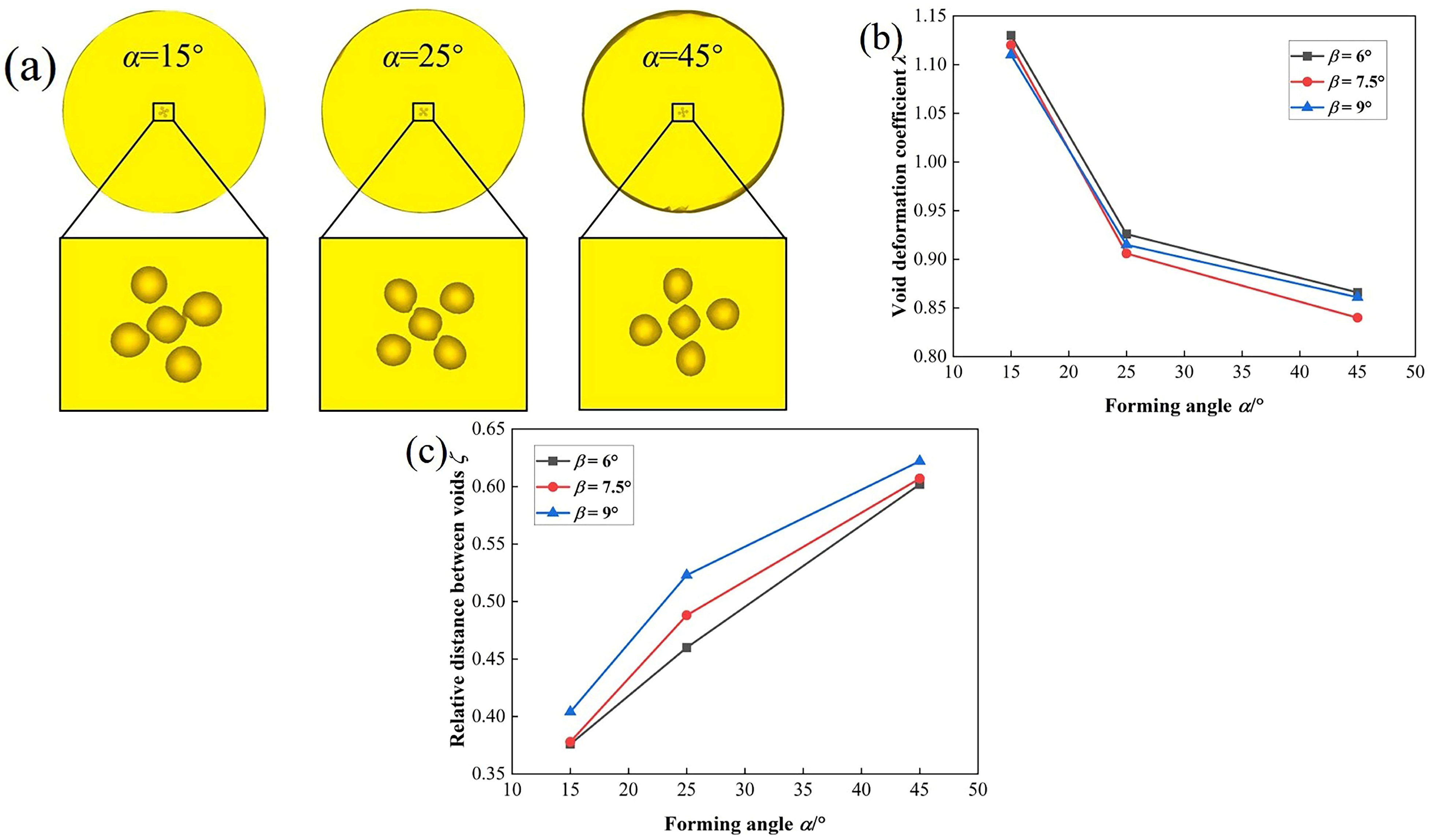
The forming angle and stretching angle are important process parameters of the CWR die. To study the influence of process parameters of CWR on void evolution, simulations of CWR of the rolled piece with voids under different process parameters are carried out. Process parameters are shown in Table 2.
(1)
Influence of forming angle on void evolution
Taking β = 7.5° as an example, the morphology of voids in the center of the rolled piece after CWR is shown in Figure 8a. The morphology of voids is similar under different forming angles, but the larger the forming angle, the smaller the volume of the voids, and the greater the distance between voids, making it difficult for void coalescence. When α = 15°, the distance between voids is very small, and even void coalescence occurs. The void deformation coefficient λ and relative distance between voids ζ under different forming angles are shown in Figure 8b–c. When the forming angle increases from 15° to 45°, the void deformation coefficient decreases, and the distance between voids increases, which indicates that the degree of expansion and coalescence of the void relative to the rolled piece gradually decreases. When α > 25°, the void deformation coefficient is less than 1, indicating that the void is smaller relative to the rolled piece. The distance between voids is also large, voids are not easy to coalesce, and the rolled piece is not prone to central defects. Thus, increasing the forming angle can reduce central defects and improve the quality of rolled pieces.
(2)
Influence of stretching angle on void evolution
Taking α = 25° as an example, the morphology of voids in the center of the rolled piece after CWR is shown in Figure 9a. Under different stretching angles, the morphology of voids and the distance between voids have little change, indicating that the stretching angle has little impact on void evolution. When the stretching angle increases from 6° to 9°, the variation of the void deformation coefficient λ and the distance between voids ζ is very small, as shown in Figure 9b,c, so the influence of the stretching angle on the void evolution is very small.

4. Scheme and Process Optimization for Avoiding Central Defects of CWR

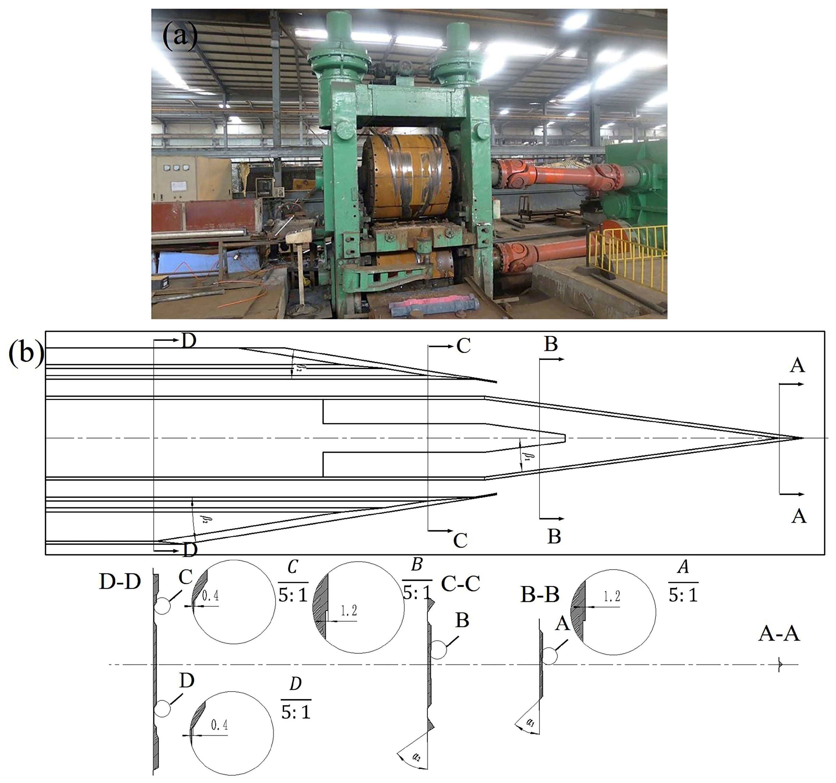
4.1. Process Scheme Design of the Detaching Die for Improving the Central Defects of CWR

It is found that the axial flow of metal is difficult in the rolled piece with small area reduction. Some metal accumulates in the rolled part of the rolled piece and is repeatedly kneaded by the dies, resulting in significant tensile stress in the center of the workpiece, which is easy to cause void expansion and coalescence. To solve this problem, the die can be stripped by reducing the height of the top surface of the die. The detaching depth of the die is 0.5 mm, as shown in Figure 10.
The central defects can be controlled by changing the process parameters of the die. According to the above conclusions, when α > 25°, the voids will shrink relative to the rolled part, and the distance between voids is large, making it difficult for void coalescence. To suppress the void expansion, the forming angle of the die is selected at 25°~45°.

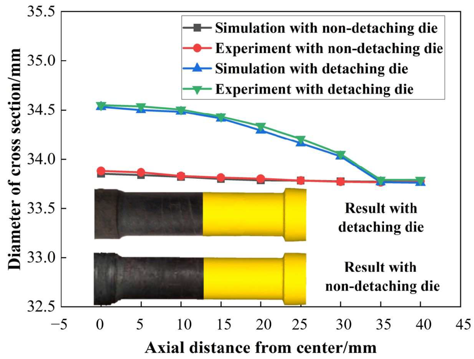
4.2. Analysis of CWR Process with After-Rolling Detaching Die

Taking the forming angle α = 35° and stretching angle β = 7.5° as an example, the finite element simulations are conducted on two working conditions of the detaching die and non-detaching die. The diameter changes of the axial symmetry plane of the rolled piece under two working conditions are shown in Figure 11. When the rolling time is less than 1.2 s, the detaching part of the die has not yet contacted with the workpiece. The change curves of the diameter under both working conditions basically coincide, and the shape changes of the workpieces are the same. When the rolling time is 1.2 s, the detaching part of the die begins to participate in rolling, some metal flows towards the detaching part, resulting in radial expansion in the axle section of the rolled piece corresponding to the detaching part of the die. Finally, the diameter of the axial symmetry plane of the rolled piece obtained by the detaching die is 34.65 mm, which is 0.82 mm larger than that obtained by the non-detaching die.
Diameters at different axial positions of CWR pieces under two working conditions are shown in Figure 12. The diameter of each axial position of the rolled piece obtained by the non-detaching die is similar, while the diameter of the rolled piece obtained by the detaching die shows obvious axial non-uniformity. The diameter of the rolled piece corresponding to the after-rolling detaching part of the die increases significantly, and the farther away from the axial symmetry plane, the smaller the diameter. Both experimental and simulation results indicate that compared to the condition with non-detaching die, the rolled piece formed by the detaching die will appear radial expansion in the detaching part. Spiral indentations will be formed on the surface of the rolled piece along the detaching line, resulting in a decrease in the accuracy of the surface.

4.3. Analysis of Stress and Strain of the CWR Piece Formed by the After-Rolling Detaching Die

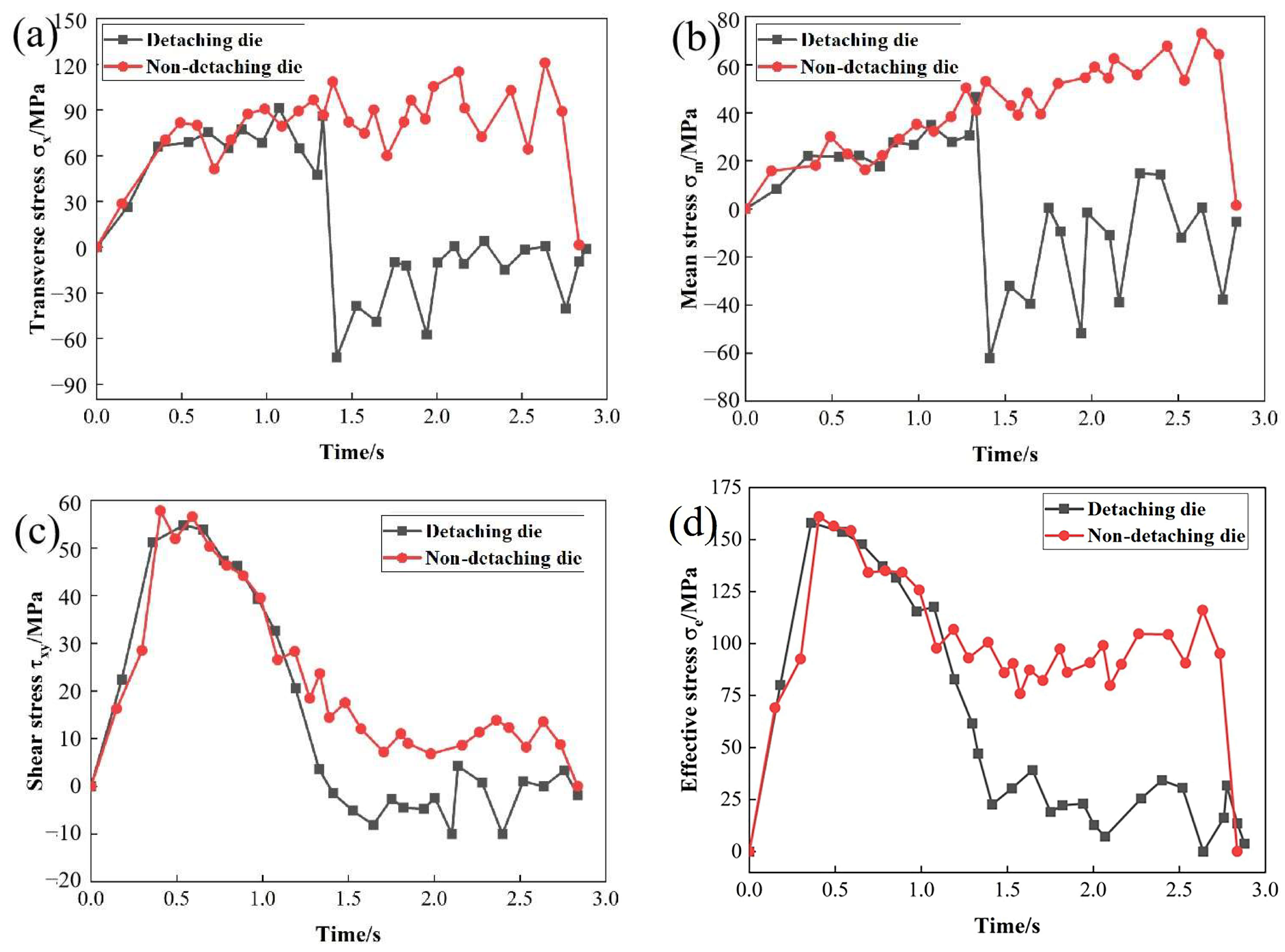
4.3.1. Analysis of Stress

Figure 13 shows the changes in transverse stress σx, mean stress σm, shear stress τxy, and effective stress σe at the center point of the rolled piece under the conditions of the after-rolling detaching die (condition 1) and non-detaching die (condition 2). When the rolling time is less than 1.2 s, because the detaching part of the die has not yet contacted with the workpiece, the level of various stress at the center point under the two working conditions is similar. After 1.2 s, the after-rolling detaching part of the die begins to participate in rolling, and the σx and σm at the center point suddenly and rapidly decrease, while those of condition 2 still maintain a high level, as shown in Figure 13a,b. According to Figure 13c,d, τxy and σe at the center point under condition 1 will decrease to varying degrees after 1.2 s.

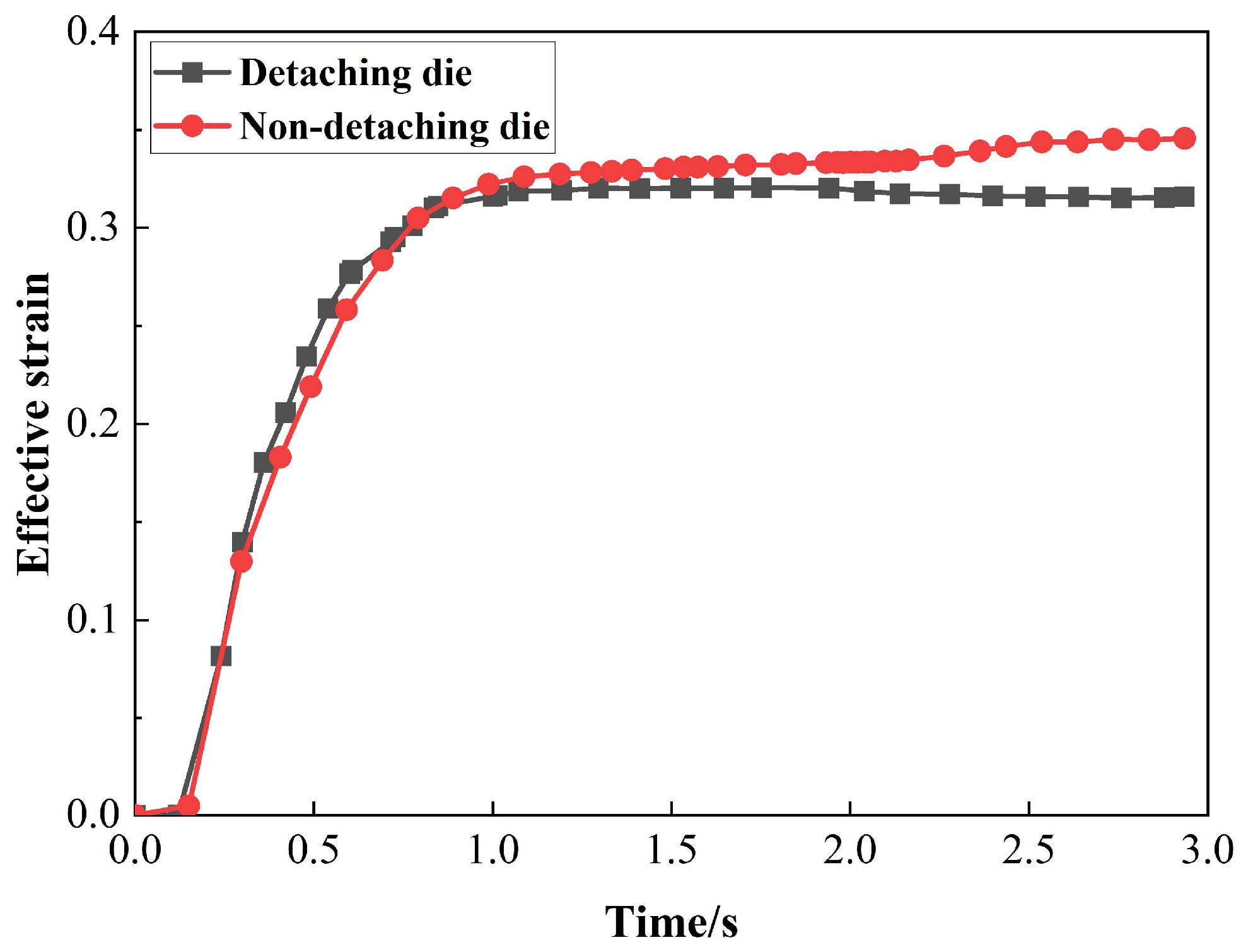
4.3.2. Analysis of Strain

According to Figure 14, at the beginning of CWR, the surface deformation of the rolled piece is very small and cannot diffuse to the center, so the effective strain at the center point is almost 0. With the increase in the wedging degree, the deformation spreads to the center, and the effective strain at the center point increases gradually. At 1.2 s, the detaching part begins to participate in rolling, and the effective strain at the center point is smaller than that under the condition of the non-detaching die. After the axial symmetry plane is formed, the effective strain at the center point remains basically unchanged when the die detaches. When the die is not detaching, the axial symmetry plane of the rolled piece is still slightly deformed due to the action of the top surface of the die wedge, so the effective strain at the center point continues to increase.
Therefore, the use of after-rolling detaching die can reduce the stress and strain at the center of the rolled piece, thereby suppressing the propagation of microcracks, improving the plasticity of the material, and improving the forming quality of the rolled piece.

4.4. Optimization of Process Parameters After-Rolling Detaching Die

The radial expansion occurs in the after-rolling detaching section of the rolled piece, and spiral indentations are formed on the surface of the rolled piece along the after-rolling detaching line, resulting in poor surface accuracy. It is necessary to determine appropriate process parameters to ensure that there is no trapped metal in the rolled part of the rolled piece to achieve accurate forming of the rolled piece. The contact area between the die and the workpiece is mainly composed of the sizing surface between the top of the die and the workpiece and the forming surface between the die inclined wedge and the workpiece, which affects the metal flow of the workpiece. The sizing surface provides the radial force, which facilitates the rounding of the formed area. The forming surface provides the radial and axial force. The axial force facilitates metal axial flow. Based on the analysis of the contact area between the die and the workpiece, the influence of process parameters on the spiral indentation of the workpiece surface under the condition of detaching die is studied and the range of process parameters is further reduced. Different process parameters are selected for finite element simulation and experiment of CWR with detaching die. The specific process parameters are shown in Table 3.

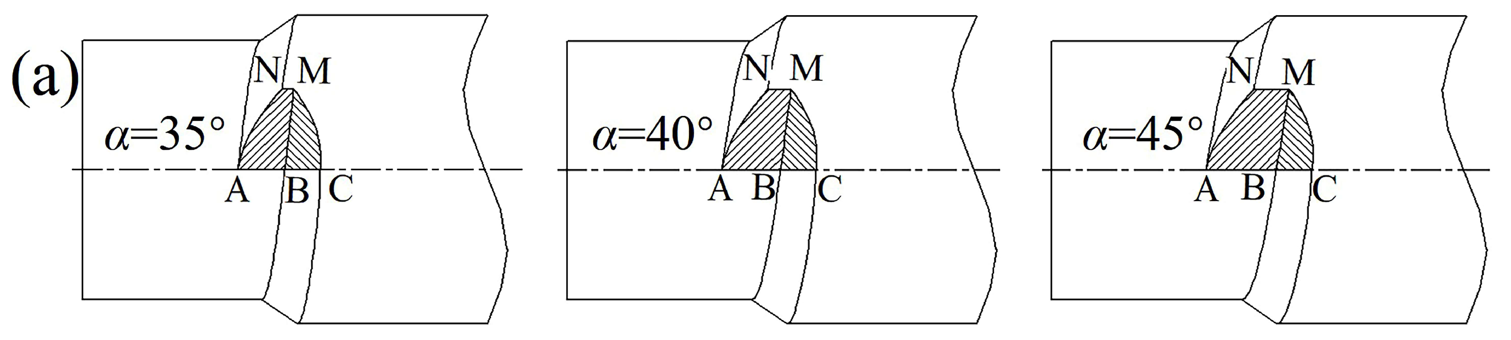
4.4.1. Influence of Forming Angle on the Formation of the Rolled Piece

Figure 15 shows the influence of forming angle on the forming quality of the rolled part. With the increase in the forming angle, the metal trapped in the after-rolling detaching part of the rolled piece is reduced, the spiral indentations become shallow (as shown in Figure 15a), the axial flow of the metal is improved, the axial distribution of the diameter is more uniform (as shown in Figure 15b), and the forming effect is better. When α = 45°, there is no trapped metal in the middle part of the rolled piece, and the diameter of the rolled piece in the after-rolling detaching part is similar to that in the non-detaching part.
Figure 16 shows the variation of the contact area between the main deformation section of the rolled piece and the die with the forming angle under the condition of after-rolling detaching die. As the forming angle increases, the radial projection area of the forming surface BCM decreases (as shown in Figure 16a), and the axial and radial projection area ratio increases (as shown in Figure 16b), which indicates that the axial force on the rolled piece increases relatively, which is conducive to achieving sufficient axial flow of the radial compressed metal. Therefore, the larger the forming angle, the better the axial flow of the metal, the less metal trapped in the after-rolling detaching part, and the radial expansion of the rolled piece is improved, which is beneficial for reducing the kneading of the metal by the die and improving the central quality of the rolled piece.

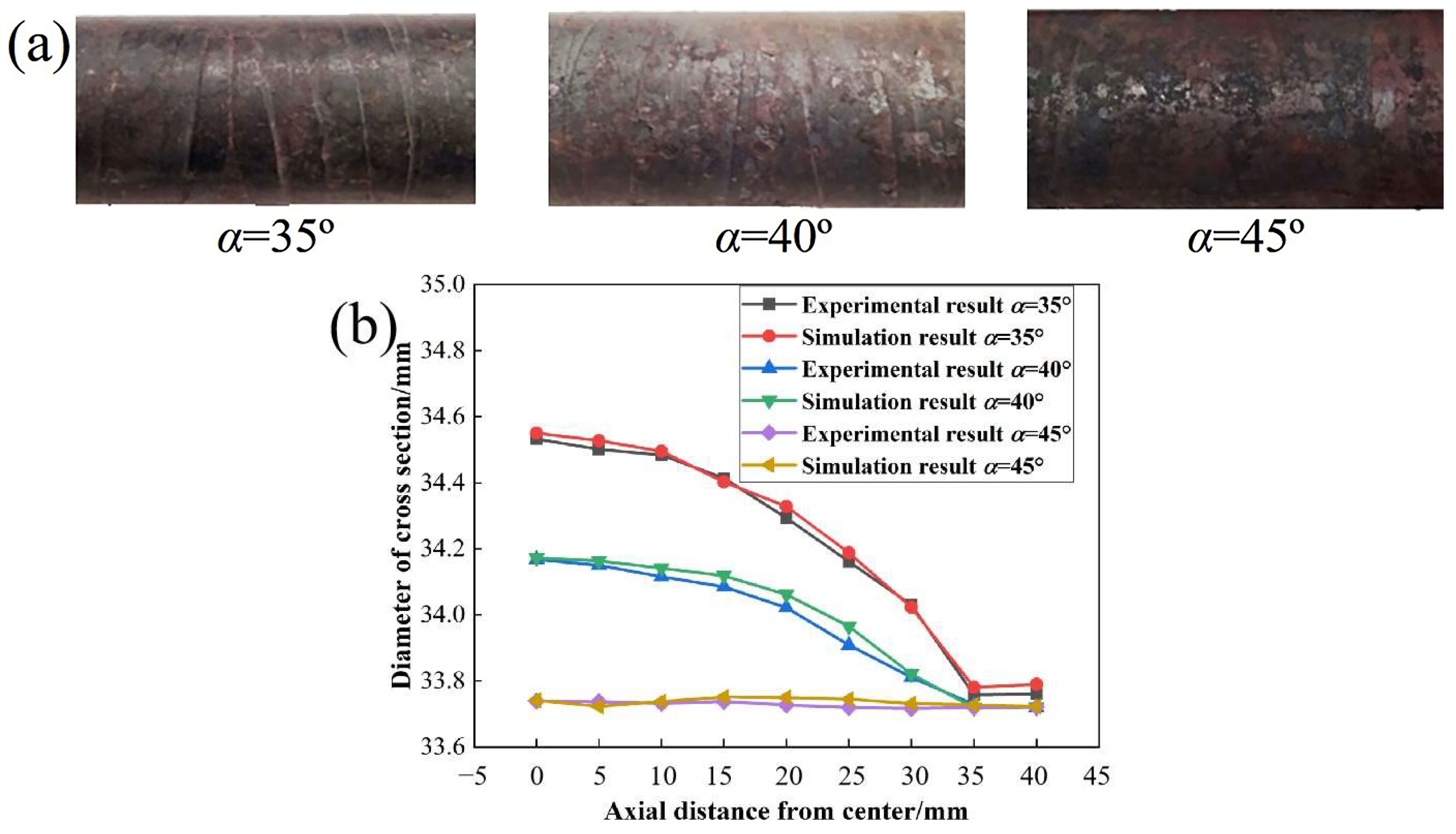
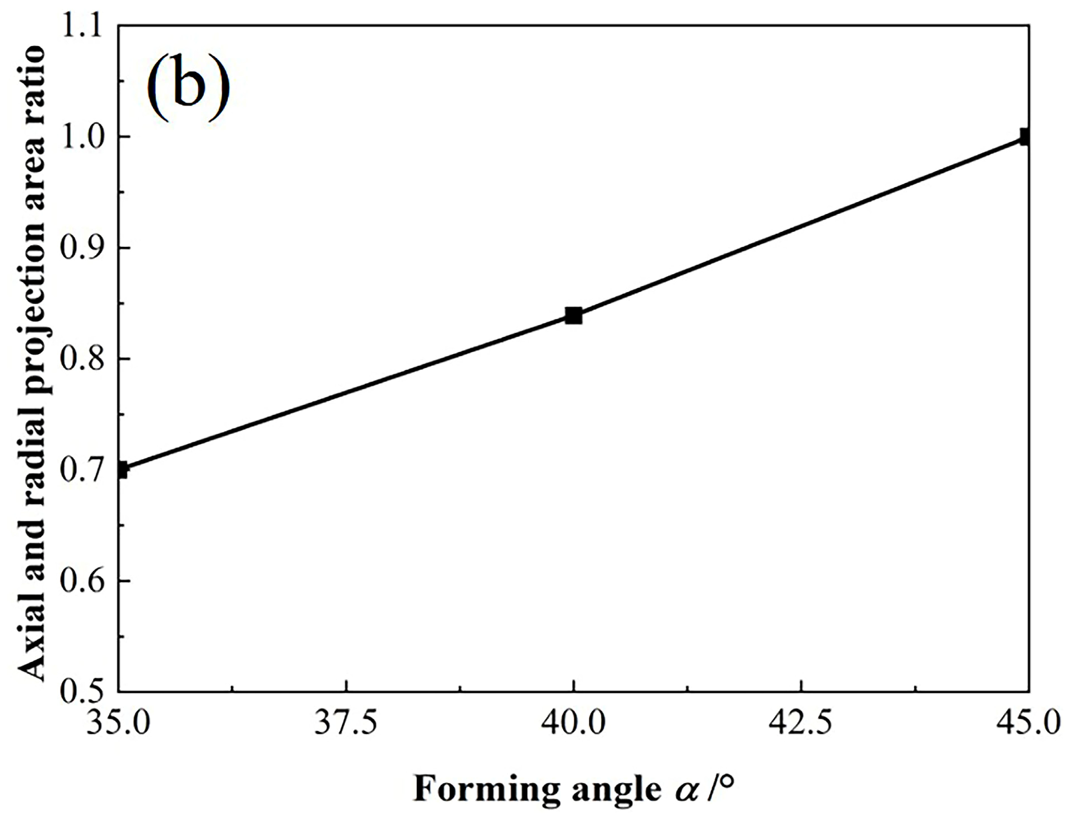
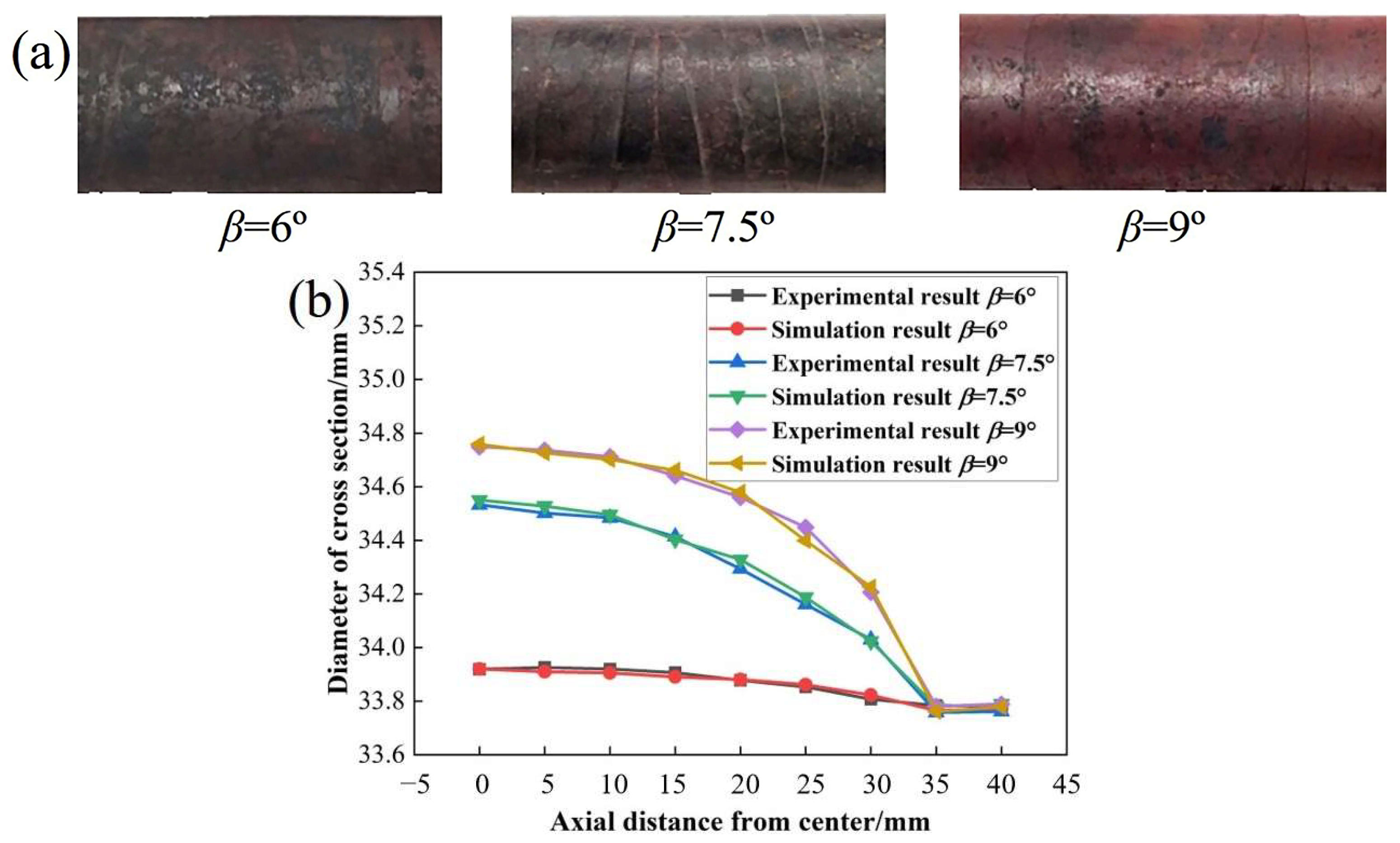
4.4.2. Influence of Stretching Angle on the Formation of the Rolled Piece

Figure 17 shows the influence of the stretching angle on the forming quality of the rolled piece. As the stretching angle increases, the metal trapped in the after-rolling detaching part of the rolled piece increases, the spiral indentations deepen, the axial flow of the metal is worse (as shown in Figure 17a), the axial distribution of the diameter is not uniform (as shown in Figure 17b) and the forming effect is worse. However, the length of the roller surface increases significantly when the stretching angle decreases.
When the forming angle and area reduction are constant, axial, and radial projection area ratio of the forming surface BCM is also constant, so the stretching angle mainly affects the area of the sizing surface ABMN. Figure 18 shows the variation of the contact surface shape and the radial projection of the sizing surface in the main deformation section with the stretching angle under the condition of after-rolling detaching die. As the stretching angle increases, the area of the sizing surface ABMN increases, and the metal flowing radially increases, which does not match the axial extension and makes it difficult for the metal to flow axially. Therefore, the larger the stretching angle, the worse the axial flow of the metal, the more metal is squeezed into the after-rolling detaching part, and the radial expansion of the rolled piece is more obvious. The metal is more susceptible to repeated kneading by the die, reducing the central quality.
Based on the above analysis, to obtain rolled pieces with good surface and central quality while minimizing the die diameter as much as possible, it is advisable to use the after-rolling detaching die with a forming angle of 45° and a stretching angle of 7.5° for CWR.

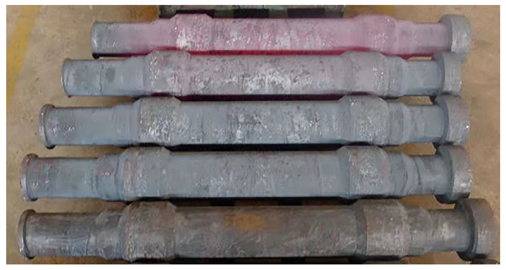
5. Experiment Validation

5.1. Experimental Arrangement

The forming experiment of railway vehicle axles is conducted on the H1400 CWR mill, as shown in Figure 19a. The die used in the experiment is shown in Figure 19b. The middle wedge is used to form the axle body with small area reduction, and the forming angle and stretching angle are α1 and β1, respectively. The wedges on both sides are used to form the axle neck of the railway vehicle axle, and the forming angle and stretching angle are α2 and β2, respectively. Due to the large experimental equipment and the complex operation of replacing the die, the optimal scheme of α1 = 45°, β1 = 7.5° is used in this experiment. The area reduction of the axle neck is about 50%, which belongs to the range of easy forming in the CWR process, so α2 = 35° and β2 = 9° are selected. The billet material is LZ50 axle steel. The specific experimental process is as follows: (1) According to the principle of constant volume, the volume of the billet is calculated according to the size of the target part and the size of the material head. In this experiment, the round billet with a diameter of 150 mm and a length of 715 mm was used, (2) before rolling, the billet is heated to 1100 °C and kept warm, (3) adjust the top and bottom dies and guide plates of the rolling mill to appropriate positions and adjust the parameters of the rolling mill. The heated billet is quickly transferred to the corresponding position of the mill to complete the rolling, (4) it is necessary to cool the rolled parts after CWR is completed. Because of the large size of the rolled parts, the air-cooling method is used.

5.2. Analysis of Experimental Results

Figure 20 shows some railway axles obtained by CWR experiment. After measurement, the diameter distribution of the rolled piece is uniform along the axial direction with little difference, and the radial size error is basically within 1 mm.
Samples are taken from each part of the axle body, wheel seat, and axle neck of the railway axle. A macrostructure test is conducted to inspect the central porosity of the railway axle of CWR. Table 4 and Table 5 show the macrostructure test results of conventional and deep etching, respectively. The results show that there are no visible defects such as shrinkage void, delamination, or cracks on the test sample. The general porosity and central porosity grades of conventional etching are both 0.5 and the general porosity and central porosity grades of deep etching are below 1.5. Therefore, all parts of the railway axle meet the technical requirements of the railway vehicle axle.
Radial and axial ultrasonic testing is conducted on the railway axle formed by CWR according to GB/T1618, and no defects are found.

6. Conclusions

The simulation and experiment are combined to study the mechanism and improvement method of central defects in CWR of railway vehicle axles. The stress variation in the CWR piece with a 30% area reduction is analyzed. At the same time, the evolution of the void defects in the center of the CWR piece is studied, and the process scheme to avoid the central defects of the rolled piece. The research results optimize the process parameters of CWR of railway vehicle axles, which is of great significance to improve the central defects of railway axles, improve the quality of CWR axles, ensure the safety of railway transportation, and guide the CWR forming process of railway axles. The CWR experiment of the railway vehicle axle is conducted, and the conclusions are as follows:
1. On the cross-section of the rolled piece, the center is subjected to tensile stress in transverse and axial directions and compressive stress in the radial direction, making it more prone to defects. On the longitudinal section of the rolled piece, the farther away from the center, the smaller the tensile stress the material is subjected to and the less likely it is to produce defects. Therefore, the center on the axial symmetry plane of the rolled piece is more prone to defects.
2. The main factors affecting the central defects of the CWR piece are transverse tensile stress, mean stress, and shear stress of cross-section. Large transverse tensile stress can easily cause micro voids in the center to expand into macro voids, resulting in central defects. The positive mean stress at the center of the rolled piece will reduce the plasticity of the material and make fracture prone. The shear stress of cross-section can cause shear deformation, which will cause lattice distortion of metal at the center of the rolled piece, resulting in central defects.
3. During CWR, there is a large strain concentration around the voids. When the void deformation coefficient is greater than 1, it indicates that the voids expand relative to the rolled piece, the distance between the voids decreases, the local deformation zone between the voids narrows, and more intense deformation is concentrated. The bearing capacity decreases, and internal necking occurs, leading to void coalescence. Ultimately, it develops into significant micro damage or even macro damage, resulting in central defects in the rolled piece.
4. As the forming angle increases, the void deformation coefficient decreases, and the distance between voids increases. That is, the degree of expansion and coalescence of voids relative to the rolled piece decreases. Therefore, increasing the forming angle can reduce central defects and improve the quality of the rolled piece. The influence of the stretching angle on the void deformation is very small.
5. The use of after-rolling detaching die can reduce the stress and strain levels at the center of the rolled part, thereby suppressing the propagation of micro cracks, improving the plasticity of the material, and improving the forming quality of the rolled part. During CWR with after-rolling detaching die if the axial flow of the metal is sufficient, the radial expansion in the axle section of the rolled piece corresponding to the after-rolling detaching part of the die will occur, resulting in an uneven axial distribution of the diameter of the rolled piece. As the forming angle increases and the stretching angle decreases, the axial flow of the metal is improved, the axial distribution of the diameter is more uniform, and the forming effect of the rolled piece is better.
6. To obtain rolled parts with good surface and central quality while minimizing the die diameter as much as possible, it is advisable to use the after-rolling detaching die with a forming angle of 45° and a stretching angle of 7.5° for rolling forming.
7. The experiment of CWR of railway vehicle axles is conducted. It is found that the general porosity and central porosity grades are below 1.5 through macrostructure test. There are no internal defects in the ultrasonic test. The railway vehicle axle formed by CWR meets the technical requirements of railway vehicle axles.

Author Contributions

Conceptualization, W.S., X.W. and C.Y.; data curation, W.S. and X.W.; funding acquisition, C.Y.; methodology, W.S., X.W. and C.Y.; resources, C.Y.; supervision, C.Y.; writing—original draft, W.S. and X.W.; writing—review and editing, W.S., X.W. and C.Y. All authors have read and agreed to the published version of the manuscript.

Funding

This work is supported by National Key R&D Program of China (Grant No. 2018YFB1307900), and Engineering Research Center of Part Near-Net-Shape Forming, Ministry of Education.

Data Availability Statement

The datasets and material generated and/or analyzed during the current study are available from the corresponding author on reasonable request.

Conflicts of Interest

The authors have no conflict of interest/competing interest to declare that are relevant to the content of this article.

References

  1. Shu, X.D.; Wei, X.H.; Li, C.M.; Hu, Z.H. The Influence Rules of Stress about Technical Parameters on Synchronous Rolling Railway Axis with Multi-Wedge Cross-Wedge Rolling. Appl. Mech. Mater. 2010, 1044, 1482–1488. [Google Scholar] [CrossRef]
  2. Gronostajski, Z.; Pater, Z.; Madej, L.; Gontarz, A.; Lisiecki, L.; Lukaszek-Solek, A.; Łuksza, J.; Mróz, S.; Muskalski, Z.; Muzykiewicz, W.; et al. Recent development trends in metal forming. Arch. Civ. Mech. Eng. 2019, 19, 898–941. [Google Scholar] [CrossRef]
  3. Li, C.M.; Shu, X.D.; Hu, Z.H. Feasibility study on multi-wedge cross wedge rolling of railway axles with finite element analysis. China Mech. Eng. 2006, 17, 2017–2019. [Google Scholar] [CrossRef]
  4. Jiang, Y.; Wang, B.Y.; Hu, Z.H.; Lin, J.G. Numerical simulation for thick-walled hollow axle during cross wedge rolling. Adv. Mater. Res. 2011, 1451, 270–273. [Google Scholar] [CrossRef]
  5. Huo, Y.M.; Bai, Q.; Wang, B.Y.; Lin, J.G.; Zhou, J. A new application of unified constitutive equations for cross wedge rolling of a high-speed railway axle steel. J. Mater. Process. Technol. 2015, 223, 274–283. [Google Scholar] [CrossRef]
  6. Huo, Y.M.; Lin, J.G.; Bai, Q.; Wang, B.Y.; Tang, X.F.; Ji, H.C. Prediction of microstructure and ductile damage of a high-speed railway axle steel during cross wedge rolling. J. Mater. Process. Technol. 2016, 239, 359–369. [Google Scholar] [CrossRef]
  7. Pater, Z.; Tomczak, J. A new cross wedge rolling process for producing rail axles. MATEC Web Conf. 2018, 190, 11006. [Google Scholar] [CrossRef] [Green Version]
  8. Pater, Z. Study of cross wedge rolling process of ba3002-type railway axle. Adv. Sci. Technol. Res. 2022, 16, 225–231. [Google Scholar] [CrossRef]
  9. Tomasz, B. Ductile fracture prediction in cross-wedge rolling of rail axles. Materials 2021, 14, 6638. [Google Scholar] [CrossRef]
  10. Jia, C.; Huo, Y.; He, T.; Hosseini SR, E.; Wu, W.; Huo, C.; Wang, B. Numerical prediction of ductile damage evolution of 40CrNiMo railway axle steel during hot cross wedge rolling. Mater. Today Commun. 2022, 33, 104942. [Google Scholar] [CrossRef]
  11. Xu, S.J.; Cui, L.Y.; Zhao, L.X.; Li, S.L.; Yang, C.P.; Xue, Z.F. Research on cross wedge rolling forming technology of railway axles. IOP Conf. Ser. Mater. Sci. Eng. 2022, 1270, 012015. [Google Scholar] [CrossRef]
  12. Gao, H.W.; Fan, Q.H.; Chu, Z.B. Simulation research on the forming process of large axles rolled by cross-wedge rolling. Trans. FAMENA 2022, 46, 63–80. [Google Scholar] [CrossRef]
  13. Huo, Y.; Huo, C.; Ren, X.; He, T.; Hosseini, S.R.E.; Wang, B.; Cui, Y.; Jia, C.; Liu, K.; Du, X. Numerical prediction of microstructure evolution of high-speed railway axle formed using hot cross wedge rolling. Mater. Today Commun. 2023, 35, 105985. [Google Scholar] [CrossRef]
  14. Dong, Y.; Tagavi, K.A.; Lovell, M.R.; Deng, Z. Analysis of stress in cross wedge rolling with application to failure. Int. J. Mech. Sci. 2000, 42, 1233–1253. [Google Scholar] [CrossRef]
  15. Li, Q.; Lovell, M.R.; Slaughter, W.; Tagavi, K. Investigation of the morphology of internal defects in cross wedge rolling. J. Mater. Process. Technol. 2002, 125–126, 248–257. [Google Scholar] [CrossRef]
  16. Li, Q.; Lovell, M.R. The establishment of a failure criterion in cross wedge rolling. Int. J. Adv. Manuf. Technol. 2004, 24, 180–189. [Google Scholar] [CrossRef]
  17. Pater, Z.; Bartnicki, J.; Samołyk, G. Numerical modelling of cross-wedge rolling process of ball pin. J. Mater. Process. Technol. 2005, 164–165, 1235–1240. [Google Scholar] [CrossRef]
  18. Wang, X.F.; Zhang, K.S.; Liu, J.P. Effect of stretching angle on internal defects in valve roughcasts produced by single cross wedge rolling. Chin. J. Eng. 2011, 33, 1538–1543. [Google Scholar] [CrossRef]
  19. Kache, H.; Stonis, M.; Behrens, B. Development of a warm cross wedge rolling process using FEA and downsized experimental trials. Prod. Eng. Res. Dev. 2012, 6, 339–348. [Google Scholar] [CrossRef]
  20. Zhou, J.; Xiao, C.; Yu, Y.Y.; Jia, Z. Influence of tool parameters on central deformation in two-wedge two-roll cross-wedge rolling. Adv. Mater. Res. 2012, 486, 478–483. [Google Scholar] [CrossRef]
  21. Wang, M.H.; Xiang, D.; Xiao, C.; Zhou, J. Influence of cooling condition of tools on central deformation of workpiece and tool wear in cross wedge rolling. Int. J. Adv. Manuf. Technol. 2012, 59, 473–482. [Google Scholar] [CrossRef]
  22. Huang, J.H.; Liu, J.P.; Wang, B.Y.; Hu, Z.H. Influence analysis of wedging tip fillet for forming in the process of cross wedge rolling 4cr9si2 valve. J. Mech. Eng. 2014, 50, 93–99. [Google Scholar] [CrossRef]
  23. Shu, X.D.; Liu, W.P.; Cheng, C.; Li, Z.; Peng, W.F.; Sun, B.S. Study on the regularity of the center quality of cross wedge rolling asymmetric shaft parts based on parity wedge. Appl. Mech. Mater. 2014, 488–489, 1125–1129. [Google Scholar] [CrossRef]
  24. Yang, C.P.; Dong, H.B.; Hu, Z.H. Micro-mechanism of central damage formation during cross wedge rolling. J. Mater. Process. Technol. 2017, 252, 322–332. [Google Scholar] [CrossRef]
  25. Zhou, X.; Shao, Z.; Pruncu, C.I.; Hua, L.; Balint, D.; Lin, J.; Jiang, J. A study on central crack formation in cross wedge rolling. J. Mater. Process. Technol. 2020, 279, 116549. [Google Scholar] [CrossRef]
  26. Zhou, X.Y.; Shao, Z.T.; Tian, F.M.; Hopper, C.; Jiang, J. Microstructural effects on central crack formation in hot cross-wedge-rolled high-strength steel parts. J. Mater. Sci. 2020, 55, 9608–9622. [Google Scholar] [CrossRef] [Green Version]
  27. Zhou, X.Y.; Shao, Z.T.; Zhang, C.; Sun, F.Z.; Zhou, W.B.; Hua, L.; Jiang, J.; Wang, L. The study of central cracking mechanism and criterion in cross wedge rolling. Int. J. Mach. Tools Manuf. 2020, 159, 103647. [Google Scholar] [CrossRef]
  28. Zhou, X.Y.; Sun, C.Y.; Wang, B.Y.; Jiang, J. Investigation and prediction of central cracking in cross wedge rolling. Int. J. Adv. Manuf. Technol. 2022, 123, 145–159. [Google Scholar] [CrossRef]
  29. Shi, M.J.; Cheng, M.; Zhang, S.H.; Tan, H.; Chen, M.; Petrenko, V.; Kozhevnikova, G.V. Central defects control of Ti-6Al-4V alloy with heavy section reduction during flat cross wedge rolling. IOP Conf. Ser. Mater. Sci. Eng. 2022, 1270, 012078. [Google Scholar] [CrossRef]
  30. Sun, W.H.; Zheng, Z.H.; Feng, P.N.; Yang, C.P. Effect of inclusions on fracture behavior of LZ50 railway axle steel during high-temperature tension. J. Mater. Eng. Perform. 2023, 32, 1–13. [Google Scholar] [CrossRef]
Figure 1. Sketch map of the railway axle.
Metals 13 01309 g001
Figure 2. Evolution of micro voids in the center of the 45 steel CWR piece: (ac) when the process parameters are inappropriate; (d) when the process parameters are good.
Metals 13 01309 g002
Figure 3. (a) Finite element model of CWR; (b) flattened diagram of the CWR tool.
Metals 13 01309 g003
Figure 4. Stress variation of characteristic points on the axial symmetry plane: (a) Transverse stress; (b) radial stress; (c) axial stress; (d) mean stress; (e) shear stress.
Metals 13 01309 g004
Figure 5. Stress variation of characteristic points on the longitudinal section: (a) Transverse stress; (b) mean stress; (c) shear stress.
Metals 13 01309 g005
Figure 6. Schematic diagram of void area and distance measurement: (a) Before CWR; (b) after CWR.
Metals 13 01309 g006
Figure 7. Void deformation behavior: (a) Variation of the void deformation coefficient λ and relative distance between voids ζ; (b) morphology of the voids and distribution of the effective strain at the specific time.
Metals 13 01309 g007
Figure 8. Influence of forming angle on void evolution: (a) Morphology of voids in the center of the rolled piece after CWR; (b) void deformation coefficient λ; (c) relative distance between voids ζ.
Metals 13 01309 g008
Figure 9. Influence of stretching angle on void evolution: (a) Morphology of voids in the center of the rolled piece after CWR; (b) void deformation coefficient λ; (c) relative distance between voids ζ.
Metals 13 01309 g009aMetals 13 01309 g009b
Figure 10. 2D and 3D drawings of the detaching die: (a) 2D drawing of the detaching die; (b) 3D drawing of the detaching die.
Metals 13 01309 g010
Figure 11. Diameter change in axial symmetry plane of the CWR piece.
Metals 13 01309 g011
Figure 12. Diameters at different axial positions of CWR pieces.
Metals 13 01309 g012
Figure 13. Stress at the center point under two working conditions: (a) Transverse stress σx; (b) mean stress σm; (c) shear stress τxy; (d) effective stress σe.
Metals 13 01309 g013
Figure 14. Effective strain at the center point under two working conditions.
Metals 13 01309 g014
Figure 15. Influence of forming angle on the formation of the rolled piece: (a) Partial view of rolled pieces; (b) axial distribution of the rolled piece diameter.
Metals 13 01309 g015
Figure 16. Variation of the contact area between the main deformation section of the rolled piece and the die: (a) Contact surface shape; (b) axial and radial projection area ratio of the forming surface.
Metals 13 01309 g016aMetals 13 01309 g016b
Figure 17. Influence of stretching angle on the formation of the rolled piece: (a) Partial view of rolled pieces; (b) axial distribution of the rolled piece diameter.
Metals 13 01309 g017
Figure 18. Variation of the contact area between the main deformation section of the rolled piece and the die: (a) Contact surface shape; (b) radial projection of the sizing surface.
Metals 13 01309 g018
Figure 19. (a) H1400 CWR mill; (b) die design drawing.
Metals 13 01309 g019
Figure 20. Some railway axles obtained by CWR experiment.
Metals 13 01309 g020
Table 1. FE simulation parameters of CWR.
FE Parameter (Unit)Value
Speed of roller (rpm)10
Initial temperature of workpiece (°C)1100
Initial temperature of tool (°C)20
Environment reference temperature (°C)20
Heat convection coefficient with air (N/s/mm/°C)0.02
Contact heat transfer coefficient (N/s/mm/°C)11
Emissivity0.8
Friction factor (workpiece and die)1
Friction factor (workpiece and guide plate)0.2
Table 2. FE simulation process parameters.
Case Numberα (°)β (°)ψ (%)
115630
27.5
39
4256
57.5
69
7456
87.5
99
Table 3. Simulation and experimental parameters.
Case Numberα (°)β (°)ψ (%)
1357.530
240
345
4356
59
67.5
Table 4. Macrostructure test results of conventional etching.
Sample PositionAxle BodyWheel SeatAxle Neck
MacrostructureMetals 13 01309 i001Metals 13 01309 i002Metals 13 01309 i003
General porosity0.50.50.5
Central porosity0.50.50.5
Table 5. Macrostructure test results of deep etching.
Sample PositionAxle BodyWheel SeatAxle Neck
MacrostructureMetals 13 01309 i004Metals 13 01309 i005Metals 13 01309 i006
General porosity1.01.01.5
Central porosity0.50.51.0
Disclaimer/Publisher’s Note: The statements, opinions and data contained in all publications are solely those of the individual author(s) and contributor(s) and not of MDPI and/or the editor(s). MDPI and/or the editor(s) disclaim responsibility for any injury to people or property resulting from any ideas, methods, instructions or products referred to in the content.

