Article

Design for the Vent Holes of Gas Turbine Flow Guide Disks Based on the Shape Optimization Method

1
AECC Hunan Aviation Powerplant Research Institute, Zhuzhou 412002, China
2
College of Energy and Power Engineering, Nanjing University of Aeronautics and Astronautics, Nanjing 210016, China
*
Authors to whom correspondence should be addressed.
Metals 2023, 13(7), 1151; https://doi.org/10.3390/met13071151
Submission received: 29 May 2023 / Revised: 19 June 2023 / Accepted: 19 June 2023 / Published: 21 June 2023

Abstract

:
Two shape optimization methods, based on non-parametric and geometric parameters, were developed to address stress concentrations in the vent holes of gas turbine flow guide disks. The design optimization focused on reducing the maximum equivalent stress at the hole edge in an aero-engine gas turbine flow guide disk. The effectiveness of both methods in achieving this objective was studied. The results indicated that the non-parametric-based optimization method reduced the maximum equivalent stress at the hole edge by 24.5% compared to the initial design, while the geometric parameter-based optimization method achieved a reduction of 20.2%. Both shape optimization methods proved effective in reducing stress concentrations and improving fatigue life. However, the non-parametric shape optimization method resulted in a better design for the vent holes based on the study’s findings.

1. Introduction

Aero-engine components feature a significant number of hole features that serve various purposes, including connection, weight reduction, air system functionality, and heat transfer. These holes play a crucial role in the overall performance and efficiency of the engine. However, it is essential to carefully consider the location and design of these holes to prevent the occurrence of severe stress concentrations at their edges. Stress concentrations can lead to structural fatigue and a reduction in a component’s overall lifespan [1,2,3,4], and the stress concentration problem has received great attention from aero-engine strength researchers [5,6]. Among the various components in an aero-engine, the gas turbine flow guide disk vent serves as a prime example, highlighting the challenges faced in the design of such component structures. The design of these structures is often constrained by the relative positions of the holes and the required cross-sectional areas. As a result, the design space for these components becomes limited, posing significant difficulties for engineers and designers.
To address these challenges and optimize the design of aero-engine components with hole features, researchers have undertaken extensive studies in the field of design optimization. These studies have aimed to enhance the performance and longevity of these components by reducing stress concentrations and improving fatigue life. Chen et al. [7,8] focused their research on a specific component—the high-pressure turbine disk-mounting side bolt hole. They approached the optimization problem by describing the hole boundary using a biaxially symmetric-shaped hole. By modeling and optimizing the geometric dimension parameters of this shaped hole, they successfully reduced the maximum equivalent stress value at the hole edge, thereby enhancing the component’s performance and fatigue life, and they also expanded the biaxial symmetry non-circular hole to the uniaxial symmetry non-circular hole and obtained different results. Sun et al. [9] pursued a different approach by conducting shape optimization based on the hyper elliptic equation and the sequential response surface method for the open hole characteristics of a rotary casing. Their research demonstrated that shape optimization techniques could effectively improve the dynamic characteristics of the structure, leading to further enhancements in performance and reliability. In another study, Yan et al. [10] employed a multi-island genetic algorithm and introduced a non-circular-shaped hole design to optimize the gas turbine flow guide disk vent hole. By combining this approach with finite element analysis sub-model technology, they successfully reduced the maximum equivalent stress value at the hole edge and improved the component’s fatigue life. In another article by Yan et al. [11], surrogate-based optimization with improved support vector regression was used for the non-circular vent hole on an aero-engine turbine disk. Hossein et al. [12,13,14] discussed the stress concentration factors (SFCs) in circular hollow-section X-connections retrofitted with a fiber-reinforced polymer under different load conditions, and the SCFs were greatly reduced. Zhu et al. [15] focused their efforts on optimizing the shape of a bolt hole in an engine sealing disk using multi-segment curves. The results of their research were impressive as they achieved a remarkable 32.8% reduction in the maximum equivalent stress at the hole edge compared to the original single round hole design. These optimization strategies have exhibited significant potential for enhancing a component’s performance and durability.
In the current research landscape, the optimization of aero-engine component designs with hole features has gained significant attention. Researchers worldwide are striving to improve the structural integrity and performance of these components through innovative approaches and advanced optimization techniques. One prominent area of research has focused on advanced optimization algorithms and methodologies. Genetic algorithms, particle swarm optimization, response surface methods, and surrogate modeling techniques are some of the widely employed optimization strategies [16,17,18,19,20,21]. These algorithms have aimed to explore the design space efficiently and identify optimal solutions that reduce stress concentrations and enhance fatigue life.
Researchers have primarily relied on traditional geometric parameter-based optimization methods and finite element analysis to enhance the design of aero-engine components featuring hole features. The studies mentioned above have demonstrated the effectiveness of various optimization techniques in reducing stress concentrations and improving the overall performance and fatigue life of these structures. However, certain limitations, such as vent area optimization, still require further exploration. By addressing these challenges, researchers can continue to advance the field and contribute to the development of more efficient and reliable aero-engine components. The current approach employed by researchers for optimizing the design of hole structural features involves using the traditional geometric parameter-based shape optimization method. This method relies heavily on the engineering design experience of researchers and utilizes specific geometric parameters such as elliptical, multi-circular arc, or shaped holes to define the design boundaries. The optimization outcomes are highly dependent on the selection of these design variables. However, an alternative approach known as non-parametric shape optimization offers a promising solution [22,23,24,25,26,27]. Unlike the traditional method, non-parametric shape optimization does not rely on geometric curves to describe the design boundaries. This method holds the potential to overcome the limitations of poor design optimization results caused by the lack of relevant structural design experience among designers. It also offers a theoretical avenue to enhance the design optimization process.
To explore the effectiveness of the non-parametric shape optimization method, this study focused on the design optimization of a gas turbine flow guide disk vent hole. By utilizing the non-parametric approach, we aimed to obtain optimal design solutions that could outperform those achieved through the traditional geometric parameter-based shape optimization method. Furthermore, a comparative study was conducted between these two methods, providing valuable insights and serving as a reference for future design optimization endeavors involving similar structural features. By adopting the non-parametric shape optimization method, researchers can aspire to enhance the efficiency and accuracy of design optimization for hole structural features, ultimately contributing to advancements in the field of engineering design and promoting innovative solutions for various applications.

2. Shape Optimization Method and Process

2.1. Geometric Parameter-Based Shape Optimization Method and Process

To ensure minimal and independent design variables, as well as facilitate ease of processing and manufacturing, researchers employing the geometrical parameters of the shape optimization method must carefully choose a suitable curve to construct the parametric model for the hole boundary. Common approaches for constructing the hole scheme include selecting straight lines, multi-segment arcs, and ellipses.
In this paper, we present the flowchart of the geometric parameter-based shape optimization method (illustrated in Figure 1). Initially, a CAD parametric model is established, where the geometric parameters are modified and linked to the CAD model. This model undergoes preprocessing through finite element software, and it is subsequently solved. The optimizer then verifies the constraints and determines if the optimization results are optimal. If the design fails to meet convergence criteria, the process returns to updating the design by modifying the CAD geometric parameter model, and the aforementioned steps are repeated. It is important to note that this optimization method requires re-meshing after each iteration, and the selection of design variables significantly impacts the resulting optimization outcomes.

2.2. Non-Parametric-Based Shape Optimization Method and Process

Non-parametric shape optimization is a method of optimizing designs that does not rely on specific geometric parameters to describe the shape. Instead, it offers flexibility by allowing the shape to be modified freely within the design space. This method is particularly useful in the finite element analysis (FEA) framework, where mesh deformation techniques can be employed to alter the mesh geometry.
In non-parametric shape optimization, the shape is typically represented using a set of control points or a mesh. The position of these control points or nodes can be adjusted to deform the shape. Mesh deformation techniques, such as the Free-Form Deformation (FFD) or Radial Basis Function (RBF) [28,29], can be utilized to smoothly modify the shape while maintaining mesh quality.
The optimization process involves defining an objective function that quantifies the desired performance of the design. This function can be based on various criteria, such as minimizing stress concentration, maximizing stiffness, or optimizing fluid flow characteristics. Additionally, constraints may be included to satisfy design requirements or limitations.
To optimize the shape, mathematical optimization algorithms, such as gradient-based or evolutionary algorithms, are employed. These algorithms iteratively adjust the positions of the control points or nodes to improve the objective function while satisfying the constraints. The optimization process continues until a satisfactory design solution is obtained [22].
Using the non-parametric shape optimization method, we can consider a hole-type structure as an example. In this approach, the coordinates of finite element nodes on the hole boundary are selected as design variables for optimization. During the optimization process, each node can be individually moved from its adjacent nodes. A schematic representation of coordinate movements for the design variable nodes is shown in Figure 2. Additionally, the nodes near the design variables can be adaptively moved, and to prevent jagged boundaries in the optimized structure, a mesh-smoothing algorithm is employed to ensure mesh quality.
In this study, we illustrated the non-parametric-based shape optimization process, as depicted in Figure 3. A finite element model of a vent hole was set up using the commercial FEA tool, ANSYS 19.2(ANSYS Inc., Pittsburgh, PA, USA). The non-parametric optimization process was performed by Tosca Structure 2020 (Dassault Systèmes, Vélizy-Villacoublay, France) and the process of minimization of the deviation from a reference stress value was based on the following hypothesis by Neuber: the optimum form of a component is achieved when the stresses running along the considered surface zone is fully constant (stress homogenization). Unlike conventional optimization iterations, our approach eliminated the need for modifying the CAD parametric model in each iteration. Instead, we directly adjusted the coordinates of the design variable nodes, thereby eliminating the time-consuming CAD parametric model modification, and then we repeated finite element pre-processing and the interpolation process for the temperature field.
Furthermore, after optimization by Tosca Structure’ shape optimization, we obtained the mesh nodes file of a vent hole, and then the coordinates of the finite element nodes were obtained by using the user-developing languages of the ANSYS 19.2, namely, the APDL scripts. Then, we reconstructed the vent hole boundary in CAD software by combining spline curves with the finite element nodes coordinates from the previous step. In this process, this integration formed the final outcome of our optimization methodology.

3. Vent Hole of a Gas Turbine Flow Guide Disk

3.1. Introduction of a Vent Hole

In this study, we focused on optimizing a gas turbine flow guide disk vent hole, which served as a representative example. Figure 4 illustrates the schematic diagram of a flow guide disk, wherein the vent holes play a crucial role in supplying cooling air to the turbine rotor. It is important to note that the location and configuration of these vent holes significantly impact the performance of the air system, as well as the fatigue life of the disk.
Considering that the positioning and size of the vent holes often result in considerable circumferential and radial stresses, the structural designer devised a solution to mitigate the stress concentration at the hole edges. As depicted in Figure 5, the designer initially employed a design approach featuring a straight line superimposed on multiple circular arcs for the hole, effectively reducing the stress concentration. By addressing these design considerations and optimizing the vent hole configuration, we aimed to enhance the overall performance and durability of the gas turbine system.

3.2. Strength Evaluation of the Initial Design

The material used for the flow guide disk was the FGH95 Ni-based superalloy, which is commonly used in aerospace and gas turbine applications, especially for aero engines in China. Some of the mechanical properties of the FGH95 superalloy are shown in Table 1.
The flow guide disk had N holes evenly distributed in the circumferential direction, and the structure and loads exhibited cyclic symmetry. To optimize the design process and save on computational time, the calculation model considered a 1/N cyclic symmetric section, which included a vent hole.
Since the vicinity of a hole was the focus of this study, in the finite element model, the mesh near the hole edge was refined based on a mesh sensitivity analysis, as shown in Figure 6. It was observed that the maximum equivalent stress near the hole edge converged when the mesh size was approximately 0.2 mm. Then, the local mesh size for strength evaluation around the hole edge was determined to be 0.2 mm, while a mesh size of 2 mm was used in the remaining regions to reduce the computational analysis time. The finite element analysis model consisted of a total of 182,490 elements, and 289,011 nodes, as depicted in Figure 7. In Figure 7, the x-axis represents the radial direction, the y-axis represents the circumferential direction, and the z-axis represents the axial direction.
The finite element model was subjected to centrifugal and temperature loads. The centrifugal loads were applied to the model in the form of a rotational speed of 20,868 r/min, while the temperature loads were applied to the nodes, and the temperature distribution was as shown in Figure 8. The axial and circumferential displacements of all the nodes on face A, as well as the axial displacements of all the nodes on face B, were constrained. Additionally, the cyclic symmetry constraint was applied to both the lower and upper boundaries.
Under the given load conditions, the linear elastic finite element simulation analysis was performed with a calculation time of approximately 5 min on an Intel Xeon E5-1620 V4 Core 32 G memory computing platform. The equivalent stress distribution of the flow guide disk was as shown in Figure 9. The maximum equivalent stress was 1513.3 MPa, and it was located at the R3 circular arc section of the hole edge, as shown in Figure 5. This indicated that the edge of the vent hole served as a weak point in the fatigue life of the flow guide disk, and the stress distributions along the upper and lower edges of the hole were closely symmetric with respect to the middle line of the enlarged position shown in Figure 9.
In order to facilitate the subsequent design optimization, the detailed stress distribution and composition of the hole’s front edge were extracted according to the normalized path of 0~0.5~1, as shown in Figure 9. Figure 10 illustrates the stress distribution along the vent hole edge of the initial design, encompassing both the equivalent stress and normal stress. An analysis of the figure revealed the following: the maximum circumferential stress (normal stress on the Y-axis) measured 1392 MPa, while the maximum radial stress (normal stress on the X-axis) amounted to 791 MPa. The circumferential stress distribution closely resembled the equivalent stress and surpassed the radial stress, implying that the circumferential stress served as the predominant stress component. Consequently, to mitigate the maximum stress value at the hole edge, the overall optimization approach proposed in this paper focused on reducing the curvature of the curve at the R3 edge of the hole and employing the “compress the upper and lower edge, stretch the left and right edge” strategy. This study incorporated methods based on geometric parameters and non-parametric techniques.

4. Design and Optimization

4.1. Geometric Parameter-Based Optimization

After conducting the aforementioned strength analysis, the vent hole scheme was redesigned in this study with the aim of reducing the stress value at the hole edge. As illustrated in Figure 11, the vent hole was modified to an elliptical shape based on our engineering experience, with the semi major axis denoted as ‘a’ and the semi minor axis denoted as ‘b’. The major axis of the ellipse defined the circumferential direction of the vent hole, while the minor axis determined the radial direction. Since the air system imposed restrictions on the vent hole cross-sectional area, the cross-sectional area of the vent hole remained constant at ‘S’. This modification addressed the stress-related concerns and ensured compliance with the vent hole cross-sectional area requirements.
In this study, the mathematical model for geometric parameter-based shape optimization can be represented by Equation (1), as follows:
min    σ e q v , max f i n d    a s . t .    S = S 0
In Equation (1), σ e q v , max is the maximum equivalent stress at the hole edge, a is the semi-major axis of the ellipse, and S represents the cross-sectional area of vent hole, which is equal to a specific value, denoted as ‘S0’, according to the requirements of the air system on the vent hole. In this case, S0 was equal to 84.198 mm2. The shape optimization method based on the geometric parameters necessitated adjustments to the relevant geometric model parameters, CAD model re-meshing, and interpolation of the temperature field during each iterative sub-step of the optimization process. Because the cross-sectional area remained basically unchanged, the variations in the vent hole had no significant impacts on the temperature field, and therefore, the temperature load of the finite element model remained unchanged during the optimization iterations. Given that the number of design variables was limited to only one, the NLPQL gradient algorithm [30] was employed in this study to expedite the optimization calculations. Figure 12 illustrates the comparison between the initial design scheme and the optimal design scheme achieved through geometric parameter-based optimization. Furthermore, Figure 13 depicts the distribution of the equivalent stress in the flow guide disk and the vent hole when employing the optimal design scheme based on the geometric parameters.
Table 2 presents a comparison of the optimization results between the initial design and the design achieved through geometric parameter-based optimization. The optimization results indicated that the semi-major axis (a) of the ellipse after optimization was 7.3 mm, corresponding to a semi-minor axis value of 3.67 mm. The area of the vent hole was 84.166 mm2, which was 0.04% smaller than the initial value of 84.198 mm2. This slight difference was acceptable within the engineering requirements for the design dimensions of the vent hole, which are typically specified to two decimal places, and it could be accommodated by the air system. The maximum equivalent stress at the hole edge in the optimal design based on the geometric parameters was 1207 MPa, reflecting a significant reduction of 20.2% compared to the initial design, which recorded a maximum equivalent stress of 1513 MPa. This improvement highlighted the effectiveness of the geometric parameter-based optimization approach in mitigating stress levels at the hole edge.

4.2. Non-Parametric-Based Optimization

For the non-parametric shape optimization of the vent hole, all nodes located along the hole’s edge were chosen as design variables. To ensure sufficient mesh quality for the finite element analysis, adaptive mesh technology was employed in Tosca Structure. This technique enables the cells surrounding a design’s variable nodes to move adaptively within a specified range, thereby maintaining a high-quality mesh around a vent hole. In this study, the optimization objective was to minimize the maximum equivalent stress at the vent hole’s edge in the flow guide disk. The specific mathematical model for this optimization process can be expressed by Equation (2), as follows:
min    σ e q v , max f i n d    N o d e i , x , y    ( i = 1 j ) s . t .    S = S 0
In Equation (2), σ e q v , max is the maximum equivalent stress at the hole edge, N o d e i , x , y is the location of node i of the hole edge, and S is the cross-sectional area of the vent hole, which is expected to be kept the same during the optimization iterations. To meet the air system’s restriction requirements for the vent hole’s cross-sectional area, the constraints were transformed to maintain the optimized structure volume equal to the initial design volume. Due to the manufacturability requirements of the vent hole, it needed to be aligned with the basic hole scheme in the axial direction. To meet the engineering manufacturing requirements, constraints were applied to the movement of these design variables. The nodes located at the same angular positions along the hole edges were selected as a group. Figure 14 illustrates the configuration of the four node groups (red nodes) established in this study, totaling 66 groups, ensuring the consistent direction and magnitude of movement for the nodes within the same groups. If this constraint was not imposed, the direction and magnitude of movement for each node within the same group would have been inconsistent, and the hole would not have been smooth along the axil direction. As a result, the optimization outcome could not have been manufactured.
The variations in the equivalent (von-Mises) stress during the iteration process is shown in Figure 15. We can see that after 46 iterations in Tosca Structure, the equivalent (von-Mises) stress of vent hole converged to 1130 MPa, and we successfully obtained the optimal results for the vent hole in the flow guide disk.
We generated an optimized 3D model by using a self-developed APDL script and spline curves. Figure 16 displays a comparison between the initial design scheme and the optimal design achieved through the non-parametric-based optimization approach. It was evident that the optimized scheme based on non-parametric optimization closely resembled the “ellipse-like” scheme derived from the geometric parameter-based optimization. Furthermore, Figure 17 presents the distribution of the equivalent stress in the flow guide disk and vent hole, highlighting the improvements achieved with the non-parametric-based optimal design.
Table 3 provides a comprehensive comparison of the optimization results between the initial design and the optimal design achieved through the non-parametric shape optimization approach. The maximum equivalent stress at the hole edge in the non-parameter-based optimal design was reduced by 24.5%, measuring 1142 MPa compared to the initial design’s stress of 1513 MPa. The non-parametric-based optimal design showcased the successful reduction in stress concentrations, resulting in a more uniform stress distribution throughout the vent hole. These improvements highlighted the effectiveness of the non-parametric approach in achieving stress reductions and enhancing the overall performance of the design. After optimization, the cross-sectional area of the vent hole was approximately 84.304 mm2, which was approximately 0.13% larger than its initial value of 84.198 mm2. This discrepancy was attributed to the error introduced by using spline curves to describe the optimized vent hole mesh boundary. However, this could be accepted by the air system requirements.

5. Discussions

Two optimization methods, namely, geometric parameter-based optimization and non-parametric optimization, were employed to optimize the vent hole in a gas turbine flow guide disk. 
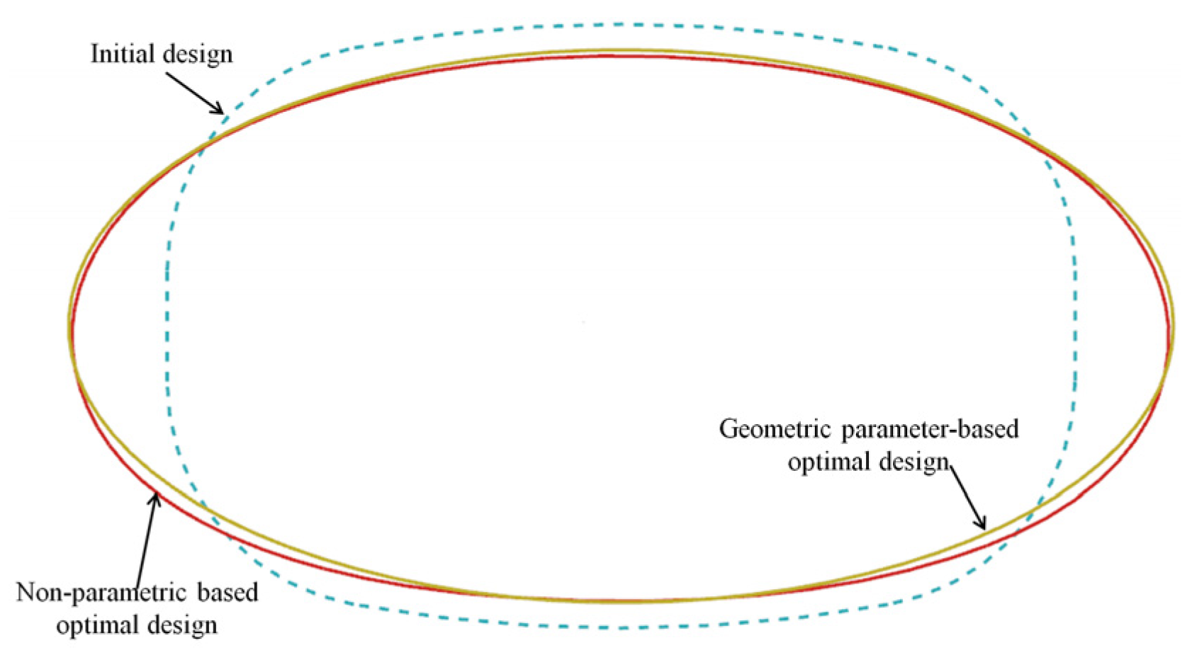
Figure 18 illustrates the design schemes of the initial design and the optimal designs obtained through the two different optimization methods. The results demonstrated significant changes in the optimal design schemes compared to the initial design. Notably, the optimal designs generated by both methods exhibited similarities, resembling elliptical shapes with slight variations in curvature at certain locations. This indicated that both optimization methods converged towards a similar optimal design solution, emphasizing the effectiveness of both approaches in achieving the desired design modifications.
Table 2 and Table 3 present the results obtained using the two different optimization methods utilized in this study. The following observations could be made:
(1) Both optimization methods resulted in an optimal vent hole design that exhibited a more uniform stress distribution compared to the initial design.
(2) Both optimal designs effectively reduced stress concentrations. The geometric parameter-based optimal design achieved a 20.2% reduction in the maximum equivalent stress, while the non-parametric-based optimal design achieved a greater reduction of 24.5% compared to the initial design. It was worth noting that the non-parametric-based shape optimization method proved to be more efficient in optimizing the maximum equivalent stress at the hole edge.
These findings demonstrated the effectiveness of both optimization methods in improving stress distribution and reducing stress concentration, with the non-parametric-based method showcasing a higher efficiency in stress optimization.
In order to gain a more detailed understanding of the differences between the two optimization methods, Figure 19 provides the equivalent stress distribution along the front edge of the vent hole for the initial design and the two optimal designs, and the following observations can be made:
(1) In comparison to the elliptical scheme, the non-parametric-based optimization resulted in a smaller curvature at the location where the maximum equivalent stress occurred. This led to a more uniform stress distribution and a lower maximum equivalent stress value.
(2) While the geometric parameter-based design achieved a 20.2% reduction in the maximum equivalent stress compared to the initial design, it is important to note that the establishment of the optimized hole shape boundary relied heavily on the engineering experience of the designer. Different designers may utilize different hole boundaries, which can result in varying design optimization outcomes.
These findings highlighted the advantages of the non-parametric-based optimization method as it provided greater flexibility in achieving an optimal stress reduction and uniform stress distribution while mitigating the dependence on individual designer experience.
Based on the fundamental knowledge of fatigue theory, it is known that reducing the maximum equivalent stress and enabling a more balanced stress distribution along the vent hole edge through optimization is beneficial for improving the fatigue life of a vent hole. A comparison of fatigue life of the vent holes before and after optimization is presented in Table 4, and it is based on our institute’s fatigue database for the FGH95 Ni-based superalloy. It can be observed that the geometric parameter-based optimal design resulted in an increase in fatigue life from 3701 cycles to 11,066 cycles, representing a 199% improvement, while the non-parametric-based optimal design yielded a fatigue life of 14,486 cycles, indicating a 291% improvement.

6. Conclusions

This study established design optimization models and processes for vent holes using geometric parameter-based and non-parameter-based designs. Two shape optimization methods have been presented, and the differences between the two optimal designs have been studied. The key conclusions from this study are as follows:
(1) The stress concentration in the vent hole was reduced and the stress distribution became more uniform after optimization compared to the initial design. This optimization method can be used as a reference for the design optimization of similar engineering structures.
(2) The geometric parameter-based optimal design achieved a 20.2% reduction in maximum equivalent stress compared to the initial design, while the non-parameter-based optimal design achieved a 24.5% reduction.
(3) The non-parametric-based shape optimization method demonstrated better optimization results and effectively avoided the poor design optimization results caused by the lack of relevant structural and strength design experience among designers.
(4) Through the application of the two optimization methods, the geometric parameter-based approach resulted in an improvement in the fatigue life of the vent hole from 3701 cycles to 11,066 cycles. Additionally, the non-parametric-based shape optimization yielded a fatigue life of 14,486 cycles.
In conclusion, this study has successfully established effective design optimization models and processes for vent holes and has provided valuable insights into the differences between geometric parameter-based and non-parameter-based optimization methods. These findings will be useful for future engineering designs.

Author Contributions

Conceptualization, C.W., Y.Z. and D.M.; methodology, C.W., Y.Z. and H.Z.; investigation, Y.Z. and Z.Q.; writing—original draft preparation, C.W., Y.Z., D.M. and Z.Q.; writing—review and editing, C.W., Y.Z., D.M., Z.Q. and H.Z.; supervision, C.W. and D.M.; project administration, D.M.; funding acquisition, D.M. All authors have read and agreed to the published version of the manuscript.

Funding

This research was funded by the Independent Innovation Special Project of AECC (grant number: ZZCX-2018-017).

Data Availability Statement

Not applicable.

Conflicts of Interest

The authors declare no conflict of interest.

References

  1. Lu, S.; Huang, Q. New method for damage tolerance analysis of turbine disk and its application. J. Aerosp. Power 2002, 17, 87–92. [Google Scholar]
  2. Li, W.; Dong, L.W.; Cai, X.H.; Zhao, F.X.; Liu, D. Structure analysis and life evaluation of the pin holes in a turbine disk of a type of aero-engine. J. Aerosp. Power 2009, 24, 1699–1706. [Google Scholar]
  3. Pedersen, N.L. Optimization of bolt thread stress concentrations. Arch. Appl. Mech. 2012, 83, 1–14. [Google Scholar] [CrossRef]
  4. Yang, J.; Li, C.B.; Xie, S.S. Multiaxial low cycle fatigue life prediction and test verification for turbine disk. J. Aerosp. Power 2011, 26, 2220–2226. [Google Scholar]
  5. Myneni, M.; Benjamin, C.C.; Rajagopal, K.R. Stress concentration factors around a circular hole in two fiber reinforced materials under large deformations. Mech. Mater. 2021, 163, 104089. [Google Scholar] [CrossRef]
  6. Zheng, C.; Zhang, G.; Mi, C. On the reduction of stress concentrations in thick-walled hollow spheres under an arbitrary uniform axial symmetric outer traction. Int. J. Press. Vessel. Pip. 2022, 194, 104545. [Google Scholar] [CrossRef]
  7. Chen, Q.; Guo, H.; Liu, X. Modeling and optimization of biaxially symmetric shaped hole structure of turbine disk. J. Aerodyn. 2013, 28, 1250–1256. [Google Scholar]
  8. Chen, Q.; Guo, H.; Zhang, C.; Liu, X. Structural optimization of uniaxial symmetry non-circular bolt clearance hole on turbine disk. Chin. J. Aeronaut. 2014, 27, 1142–1148. [Google Scholar] [CrossRef] [Green Version]
  9. Sun, S.P.; Hu, J.T.; Zhang, W.H. Optimization of slewing shell opening shape based on hyperelliptic equation and sequential response surface method. J. Aeronaut. 2015, 36, 3595–3607. [Google Scholar]
  10. Yan, C.; Zhu, J.; Shen, X.; Fan, J.; Jia, Z.; Chen, T. Structural design and optimization for vent holes of an industrial turbine sealing disk. Chin. J. Aeronaut. 2021, 34, 265–277. [Google Scholar] [CrossRef]
  11. Yan, C.; Yin, Z.; Shen, X.; Mi, D.; Guo, F.; Long, D. Surrogate-based optimization with improved support vector regression for non-circular vent hole on aero-engine turbine disk. Aerosp. Sci. Technol. 2020, 96, 105332. [Google Scholar] [CrossRef]
  12. Nassiraei, H.; Rezadoost, P. Stress concentration factors in tubular X-connections retrofitted with FPR under compressive load. Ocean. Eng. 2021, 229, 108562. [Google Scholar] [CrossRef]
  13. Nassiraei, H.; Rezadoost, P. SCFs in tubular X-connections retrofitted with FPR under in-plane bending load. Compos. Struct. 2021, 274, 114314. [Google Scholar] [CrossRef]
  14. Nassiraei, H.; Rezadoost, P. SCFs in tubular X-joints retrofitted with FPR under out-of-plane bending moment. Mar. Struct. 2021, 79, 103010. [Google Scholar] [CrossRef]
  15. Zhu, J.H.; Li, J.; Zhang, W.; Meng, L.; Wang, D. Application of modern shape optimization techniques in aero-engine component design. Aerosp. Manuf. Technol. 2012, 23/24, 30–35. [Google Scholar]
  16. Movahedi, S.; Taghizadieh, N. Efficiency improvement of radial basis function meshless method in conjunction with bayesian theorem for electrical tomography of heterogeneous concrete. Eng. Anal. Bound. Elem. 2021, 135, 382–393. [Google Scholar] [CrossRef]
  17. Luh, G.C.; Lin, C.Y. Optimal design of truss-structures using particle swarm optimization. Comput. Struct. 2011, 89, 2221–2232. [Google Scholar] [CrossRef]
  18. Cao, Z.; Lin, G.; Shi, Q.; Cao, Q. Optimization analysis of NURBS curved variable stiffness laminates with a hole. Mater. Today Commun. 2022, 31, 103364. [Google Scholar] [CrossRef]
  19. Gunasekaran, V.; Gulhane, S.; Gupta, S.; Pitchaimani, J.; Rajamohan, V.; Manickam, G. Structural–Acoustic Response Analysis of Variable Stiffness Laminates with Inherent Material Damping. Int. J. Struct. Stab. Dyn. 2022, 22, 2250127. [Google Scholar] [CrossRef]
  20. Joseph, G.J.; Mohan, G.; Harikrishna, V.; Sandra, M.V.; Sajith, A.S. Size Optimization of Truss Structures Using Real-Coded Genetic Algorithm with a Novel Constraint Handling Method. In Proceedings of the International Conference on Structural Engineering and Construction Management, Angamaly, India, 1–3 June 2022; Springer: Cham, Switzerland, 2022; Volume 284, pp. 915–923. [Google Scholar]
  21. Tian, D.; Shi, Z. MPSO: Modified particle swarm optimization and its applications. Swarm Evol. Comput. 2018, 41, 49–68. [Google Scholar] [CrossRef]
  22. Hahn, Y.; Cofer, J.I. Study of Parametric and Non-Parametric Optimization of a Rotor-Bearing System. In Turbo Expo: Power for Land, Sea, and Air; American Society of Mechanical Engineers: New York, NY, USA, 2014. [Google Scholar] [CrossRef]
  23. Chen, J.; Shapiro, V.; Suresh, K.; Tsukanov, I. Parametric and Topological Control in Shape Optimization. In Proceedings of the 32nd Design Automation Conference, Part A and B, Philadelphia, PA, USA, 10–13 September 2006; pp. 575–586. [Google Scholar]
  24. Shimoda, M.; Nagano, T.; Shi, J.-X. Non-parametric shape optimization method for robust design of solid, shell, and frame structures considering loading uncertainty. Struct. Multidiscip. Optim. 2019, 59, 1543–1565. [Google Scholar] [CrossRef]
  25. Shimoda, M.; Liu, Y.; Morimoto, T. Non-parametric free-form optimization method for frame structures. Struct. Multidiscip. Optim. 2014, 50, 129–146. [Google Scholar] [CrossRef]
  26. Liu, Y.; Shimoda, M. Non-parametric shape optimization method for natural vibration design of stiffened shells. Comput. Struct. 2015, 146, 20–31. [Google Scholar] [CrossRef]
  27. Lee, J.-R.; Harland, A.; Roberts, J. Non-Parametric Shape Optimization of a Football Boot Bottom Plate. Proceedings 2020, 49, 152. [Google Scholar]
  28. Xu, G.; Wang, G.-Z.; Chen, X.-D. Free-Form Deformation with Rational DMS-Spline Volumes. J. Comput. Sci. Technol. 2008, 23, 862–873. [Google Scholar] [CrossRef]
  29. Llorens, A.d.T.; Kiendl, J. An isogeometric finite element-boundary element approach for the vibration analysis of submerged thin-walled structures. Comput. Struct. 2021, 256, 106636. [Google Scholar]
  30. Zhang, Y.; Xie, J.L. Truss structural optimization based on NLPQL and MIGA. Appl. Mech. Mater. 2013, 365–366, 150–154. [Google Scholar] [CrossRef]
Figure 1. Flowchart of geometric parameter-based shape optimization.
Metals 13 01151 g001
Figure 2. Schematic of design node movement for a hole-type structure.
Metals 13 01151 g002
Figure 3. Flowchart of non-parametric-based shape optimization.
Metals 13 01151 g003
Figure 4. 
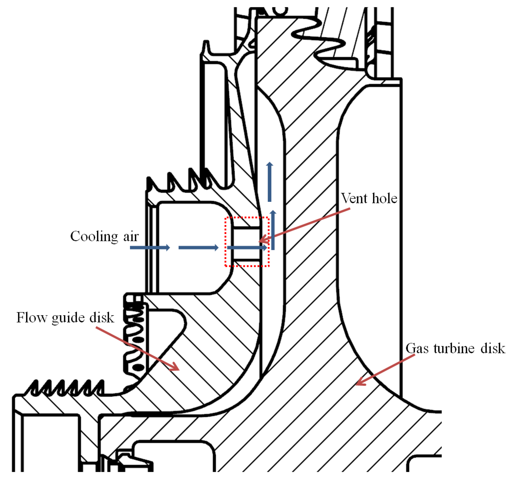
Schematic diagram of the gas turbine flow guide disk.
Metals 13 01151 g004
Figure 5. Schematic diagram of the vent hole (initial design).
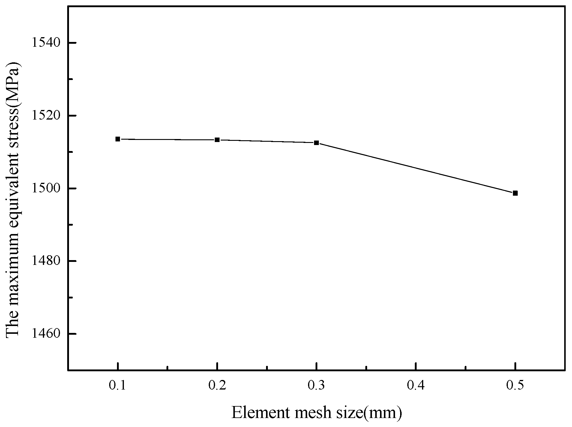
Metals 13 01151 g005
Figure 6. Mesh sensitivity analysis of the finite element model.
Metals 13 01151 g006
Figure 7. Finite element mesh of the gas turbine flow guide disk.
Metals 13 01151 g007
Figure 8. Temperature distribution of the gas turbine flow guide disk.
Metals 13 01151 g008
Figure 9. Equivalent stress distributions in the gas turbine flow guide disk’s initial design.
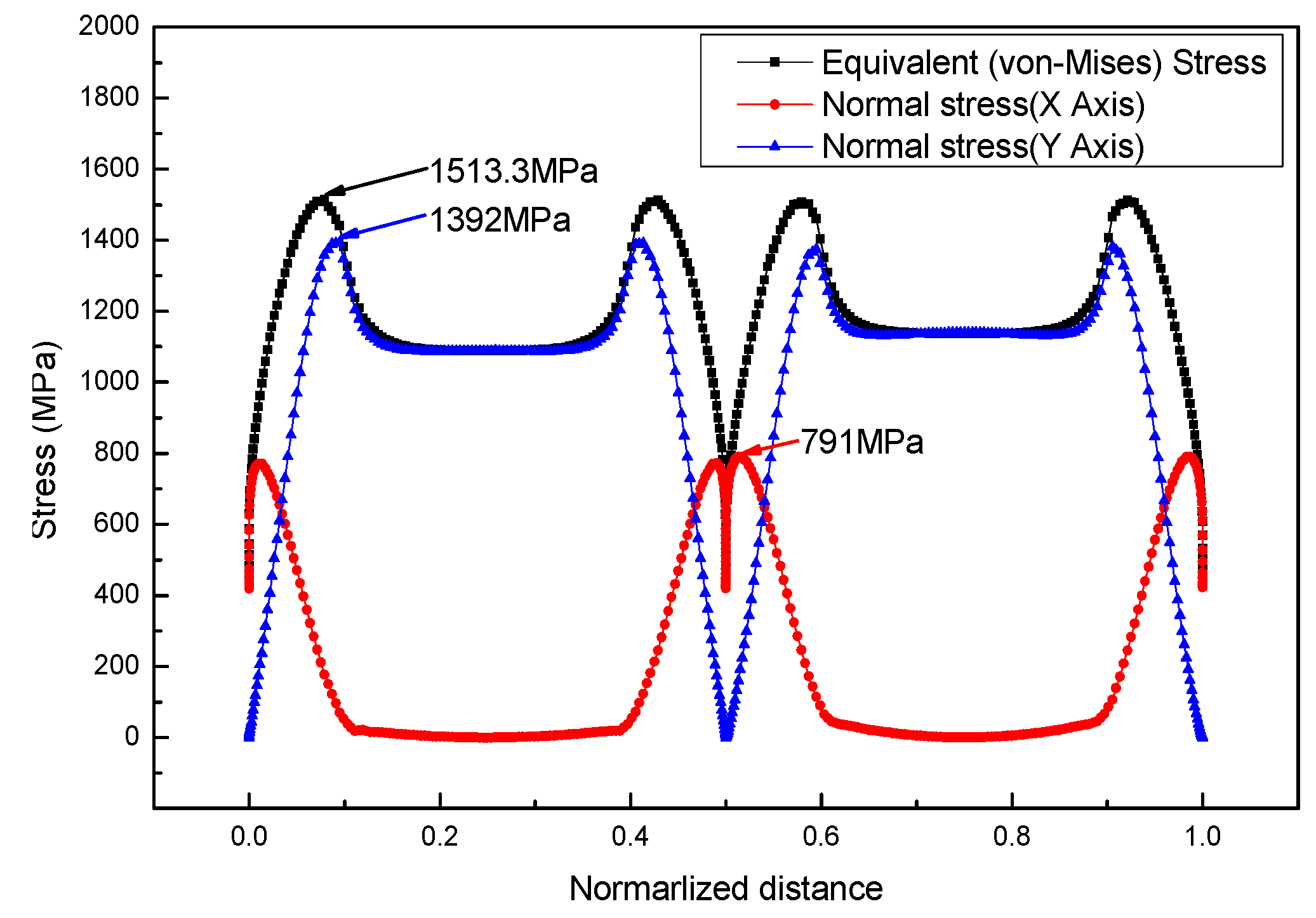
Metals 13 01151 g009
Figure 10. Stress distribution along the vent hole edge in the initial design.
Metals 13 01151 g010
Figure 11. Schematic diagram of the vent hole based on the geometric parameters for vent holes.
Metals 13 01151 g011
Figure 12. Comparison of the schemes between the initial design and the geometric parameter-based optimal design.
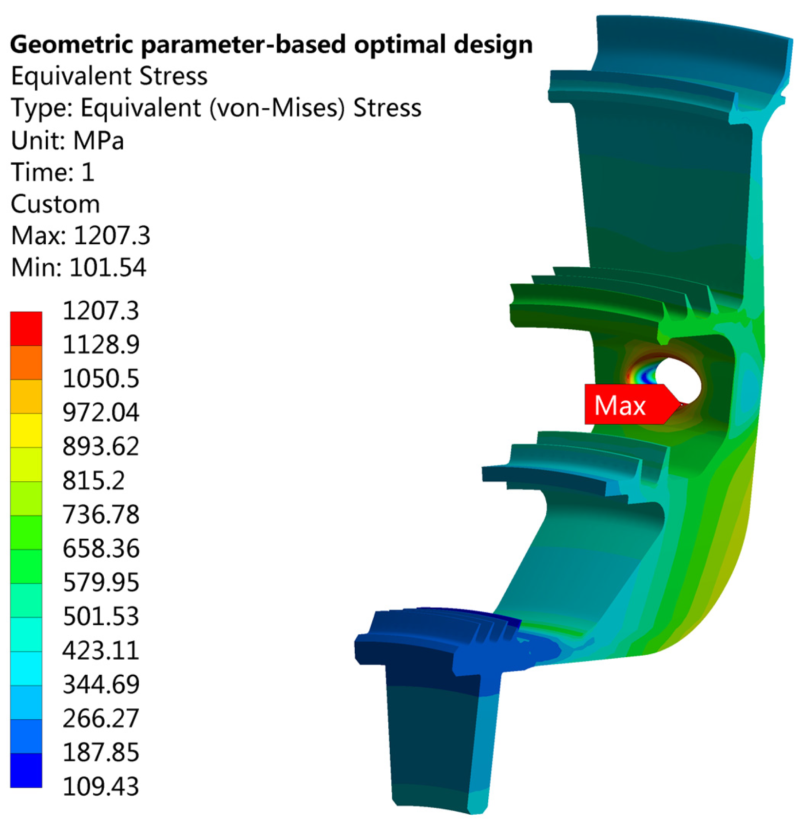
Metals 13 01151 g012
Figure 13. Equivalent stress distribution in the geometric parameter-based optimal design.
Metals 13 01151 g013
Figure 14. Equivalent stress distribution of the geometric parameter-based optimal design.
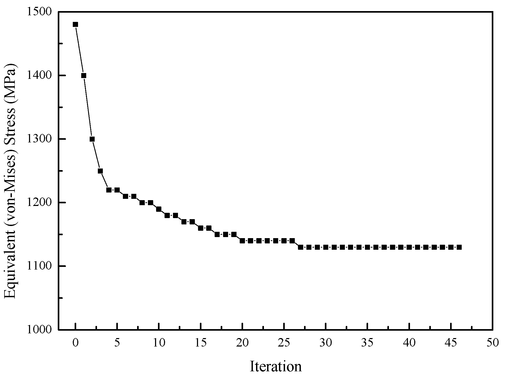
Metals 13 01151 g014
Figure 15. The variations in the equivalent (von-Mises) stress during the iterative process.
Metals 13 01151 g015
Figure 16. 
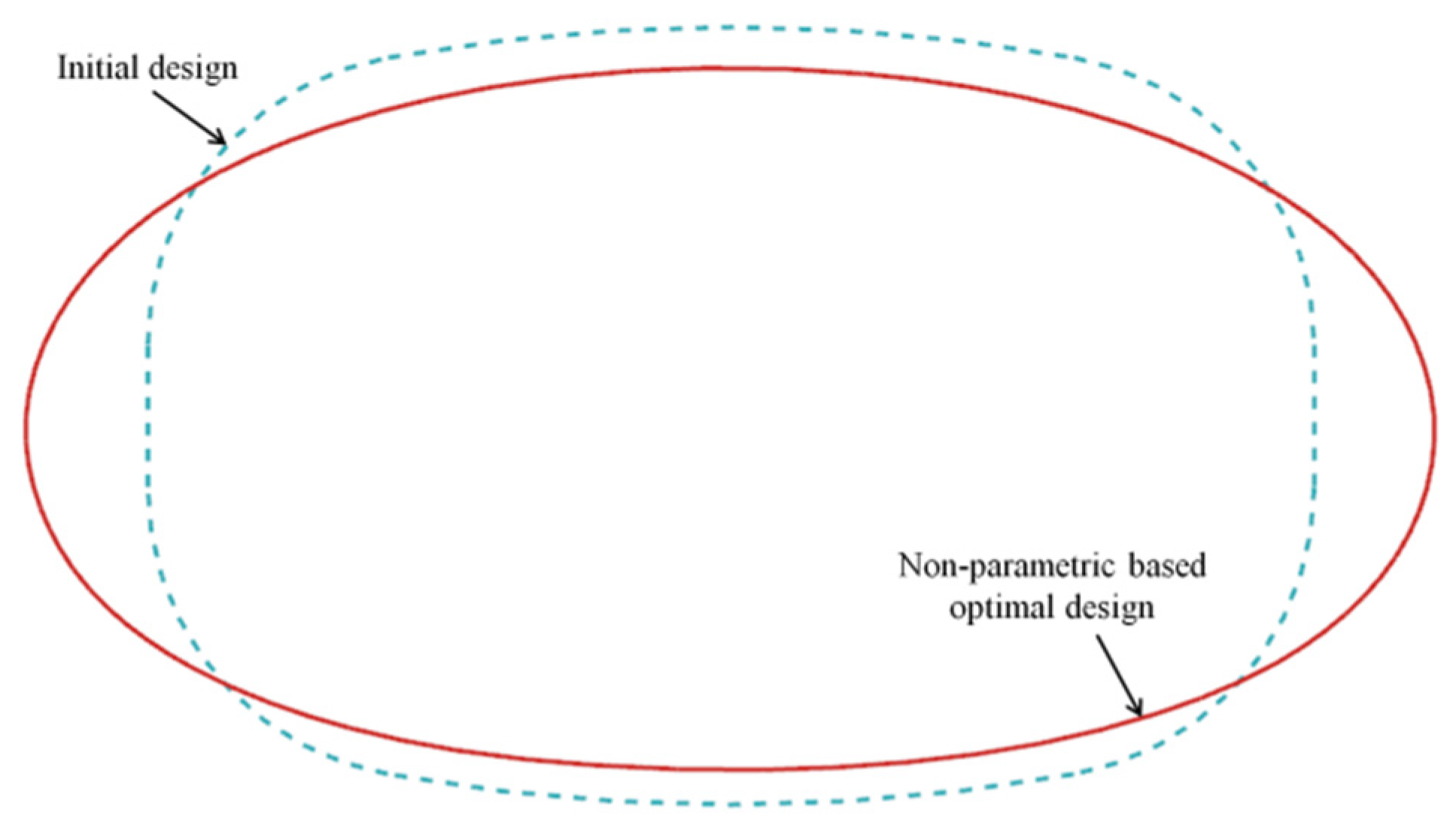
Comparison of the schemes between the initial design and the non-parametric-based optimal design.
Metals 13 01151 g016
Figure 17. Equivalent stress distribution of the non-parametric-based optimal design.
Metals 13 01151 g017
Figure 18. Comparison of the schemes between the initial design and two different optimization methods.
Metals 13 01151 g018
Figure 19. Comparison of the equivalent stress distribution along the vent hole edge between the different designs.
Metals 13 01151 g019
Table 1. Mechanical properties of FGH95.
Temperature (°C)Young’s Modulus
E (GPa)
Poisson’s Ratio
μ
Yield Strength
σ0.2 (MPa)
Ultimate Strength
σb (MPa)
Density
(kg/m3)
25214.40.305120016008270
500197.20.33711401520
Table 2. Comparison of the results between the initial design and the geometric parameter-based optimal design.
Parametersa/mmS/mm2 σ e q v , max / MPa
Initial design-84.1981513
Geometric parameter-based optimal design7.384.1661207
Difference (%)-−0.04%−20.2%
Table 3. Non-parametric shape optimization-based method before and after the optimization results.
ParametersS/mm2 σ e q v , max / MPa
Initial design84.1981513
Non-parametric-based optimal design84.3041142
Difference (%)+ 0.13%−24.5%
Table 4. Comparison of fatigue life between the different designs.
ParametersInitial DesignGeometric Parameter-Based Optimal DesignNon-Parametric-Based Optimal Design
Nf/cycles370111,06614,486
Disclaimer/Publisher’s Note: The statements, opinions and data contained in all publications are solely those of the individual author(s) and contributor(s) and not of MDPI and/or the editor(s). MDPI and/or the editor(s) disclaim responsibility for any injury to people or property resulting from any ideas, methods, instructions or products referred to in the content.

