
A Novel Electrode Front-End Face Design to Improve Geometric Accuracy in Electrical Discharge Machining Process

Abstract
:1. Introduction
2. Methodology
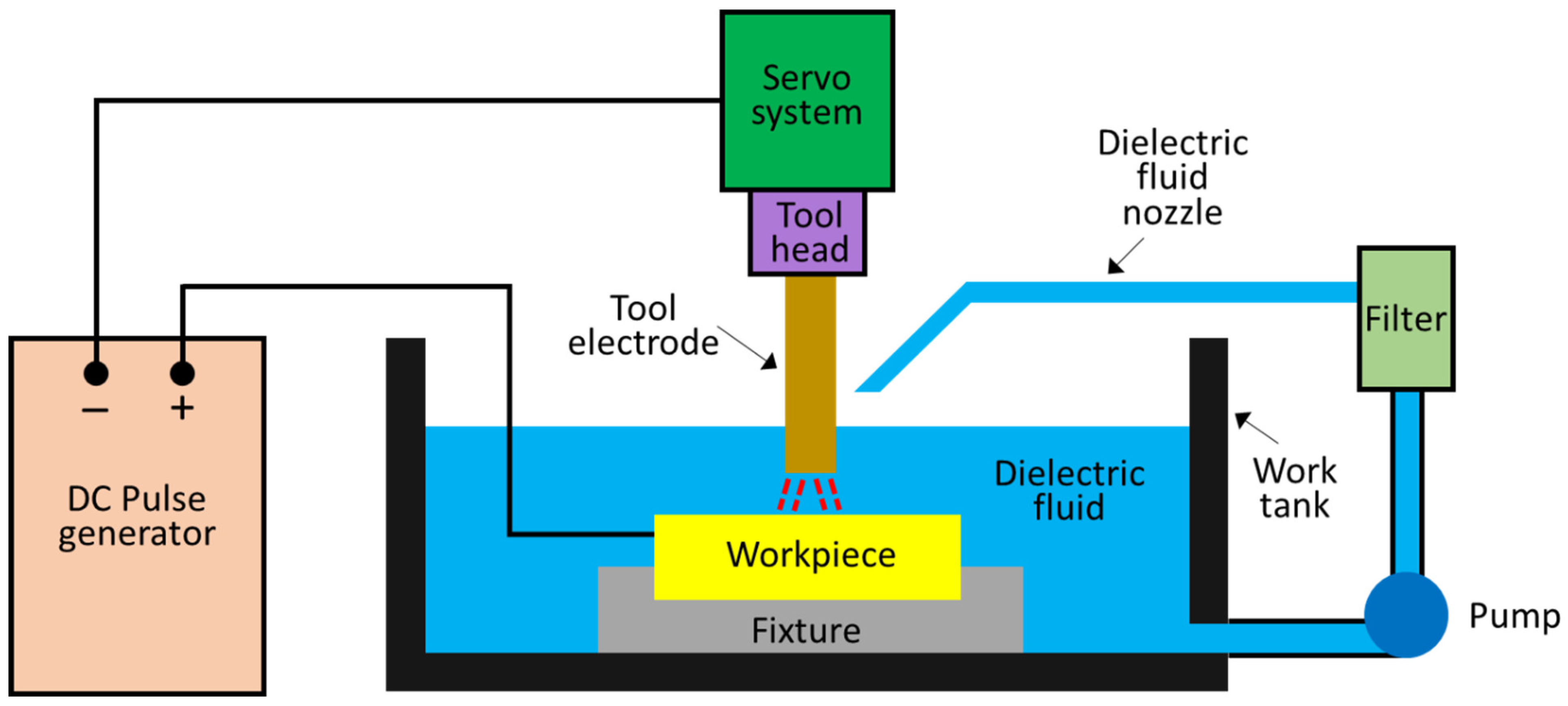
2.1. Experiment Condition and Equipment
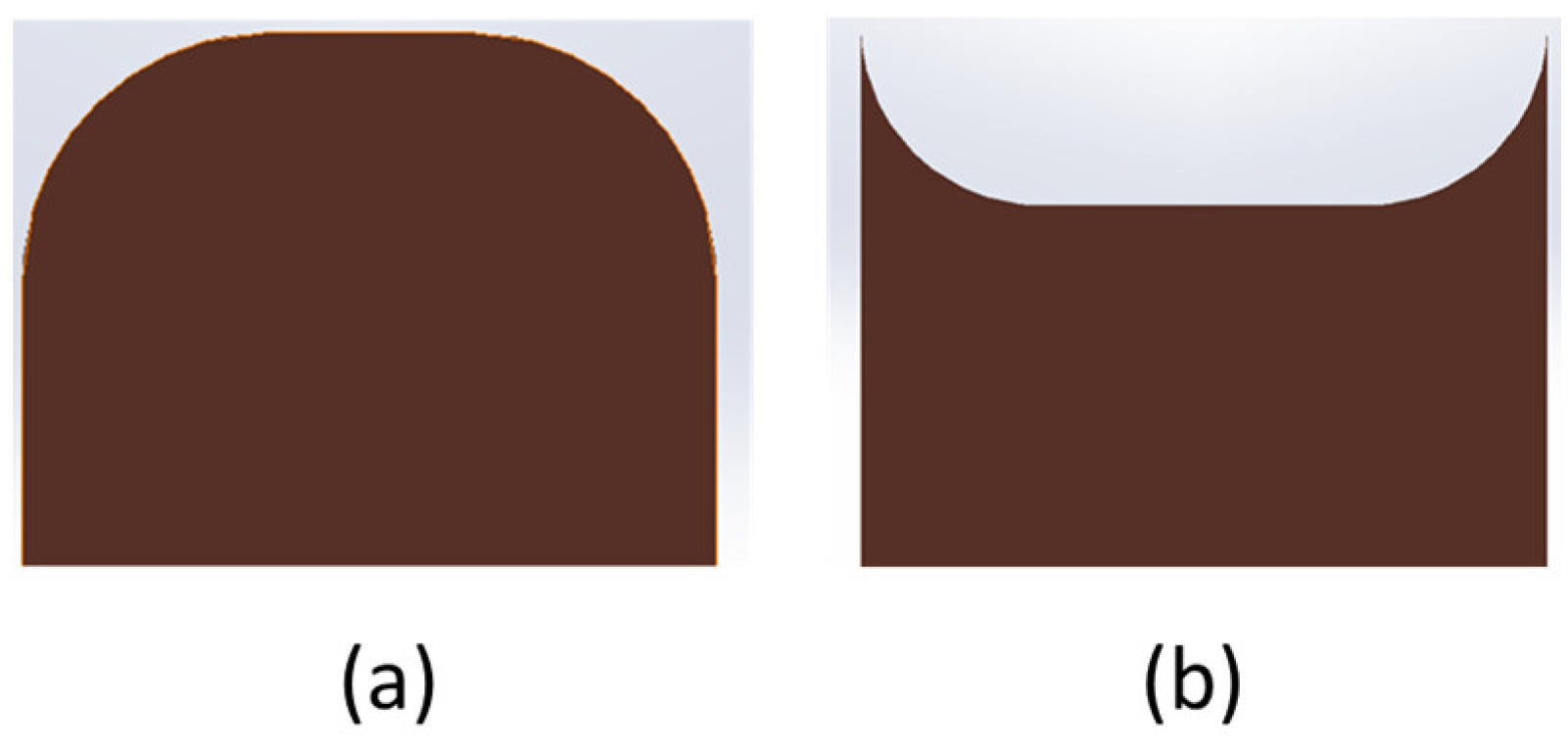
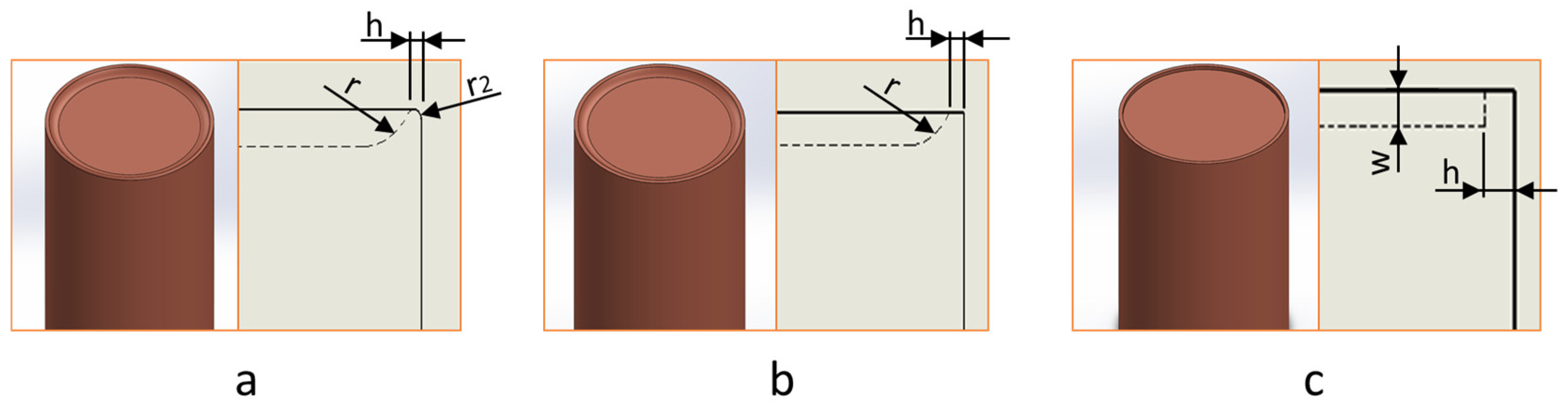
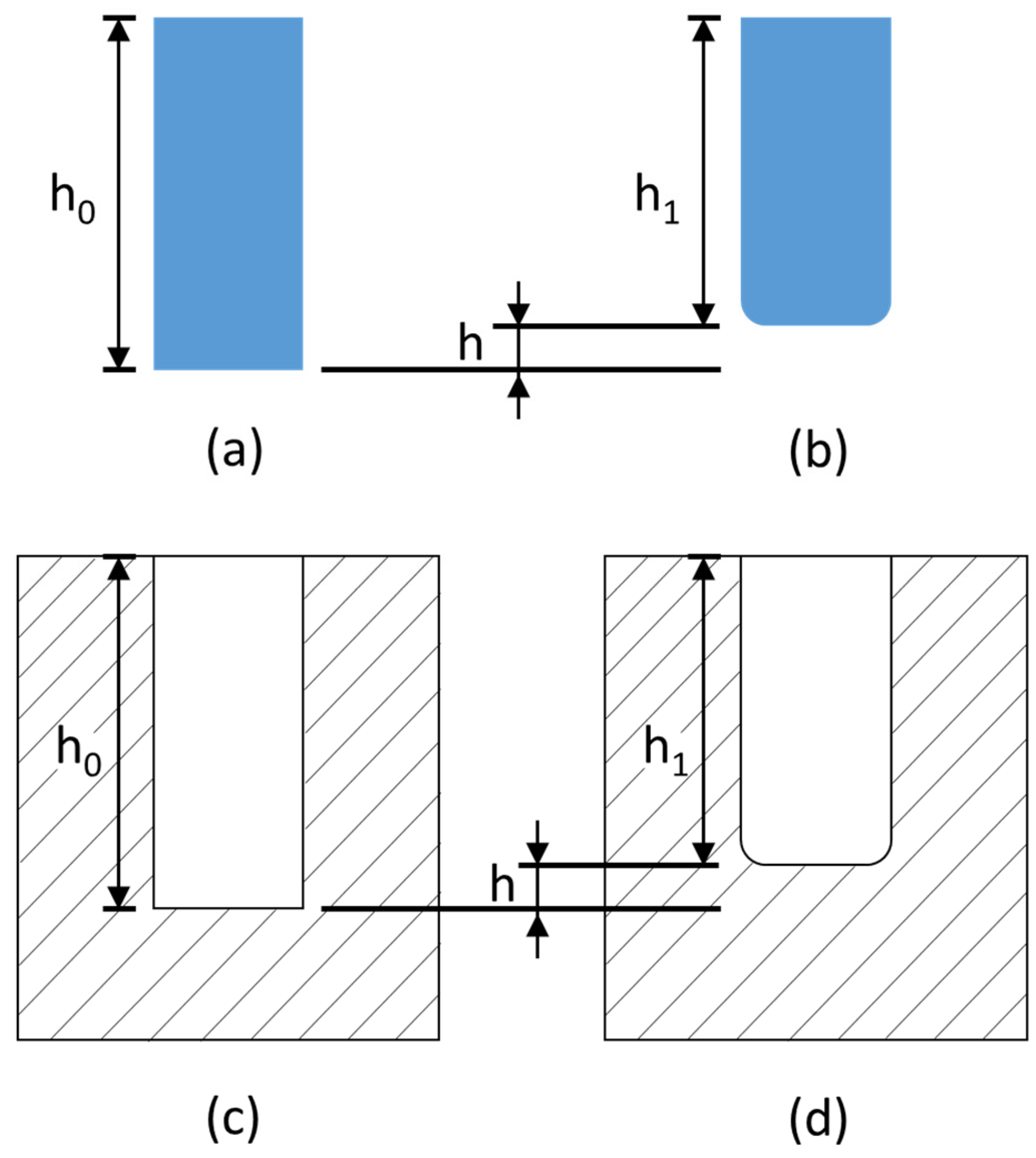
2.2. Electrode Front-End Face Design
3. Results and Discussion
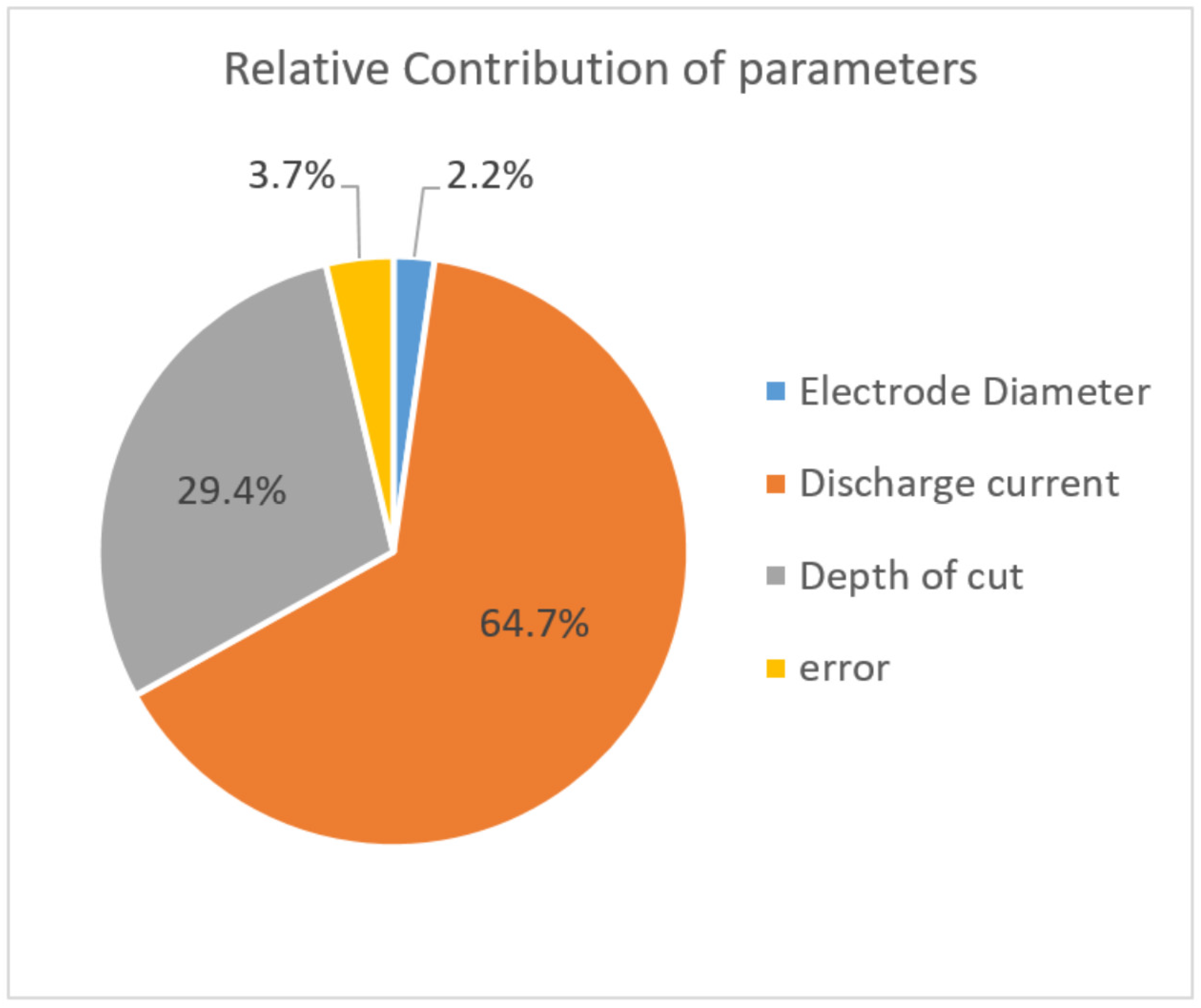
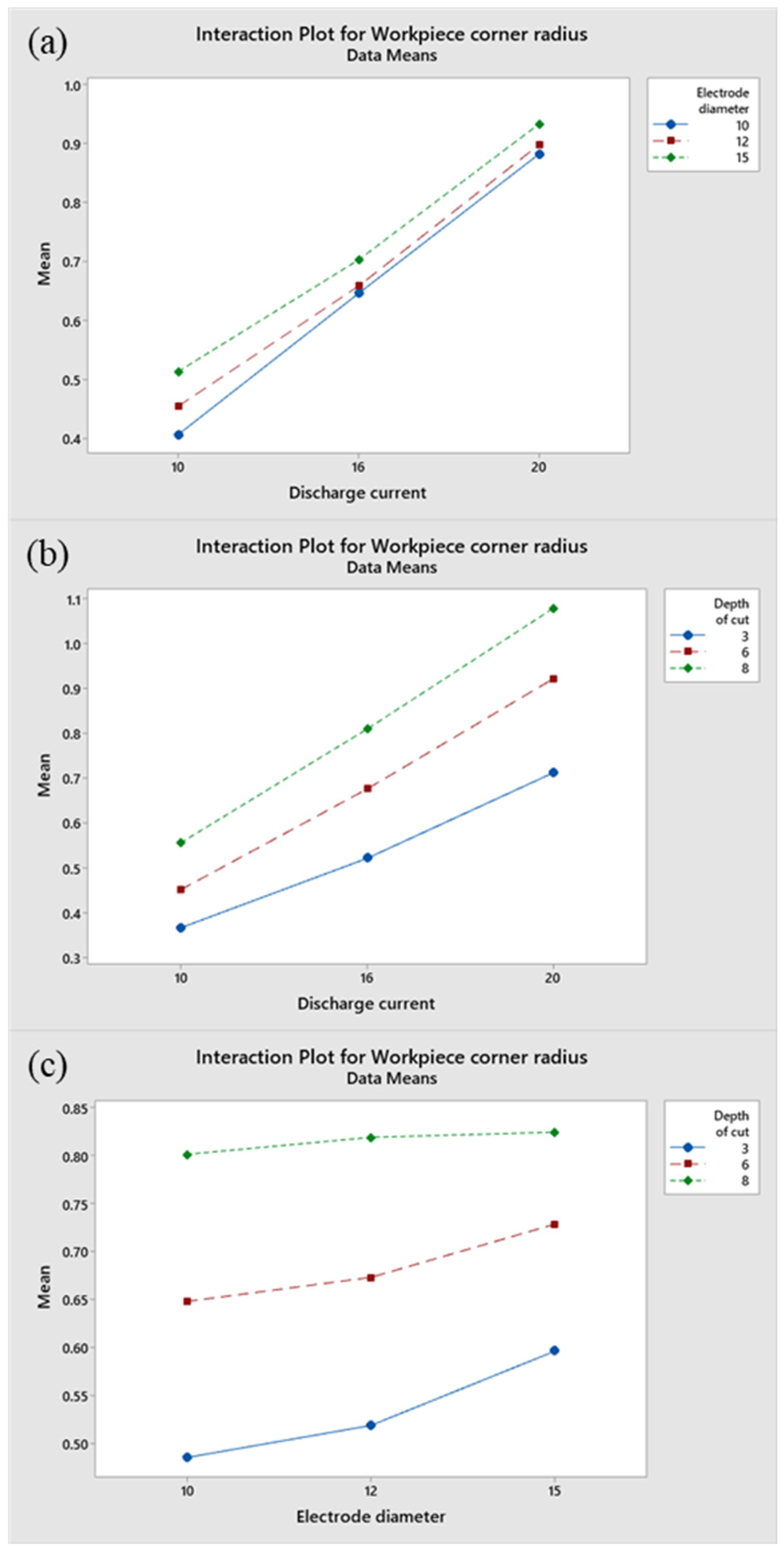
3.1. Mathematical Model Analysis
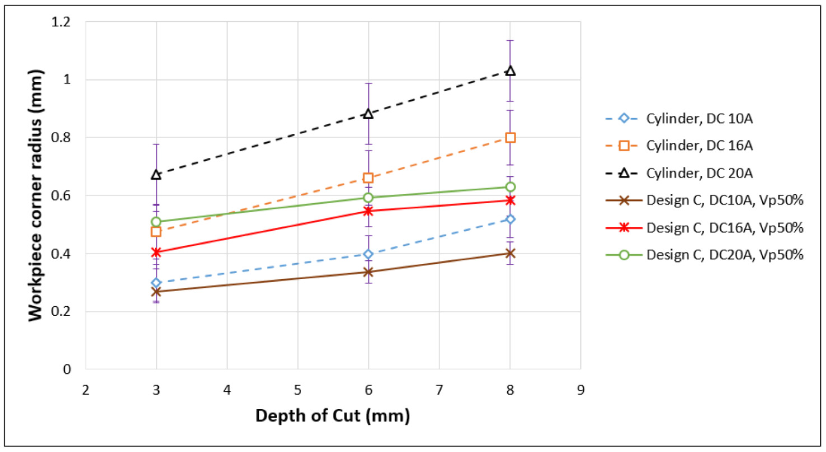
3.2. Analysis of Electrode Front-End Face Design
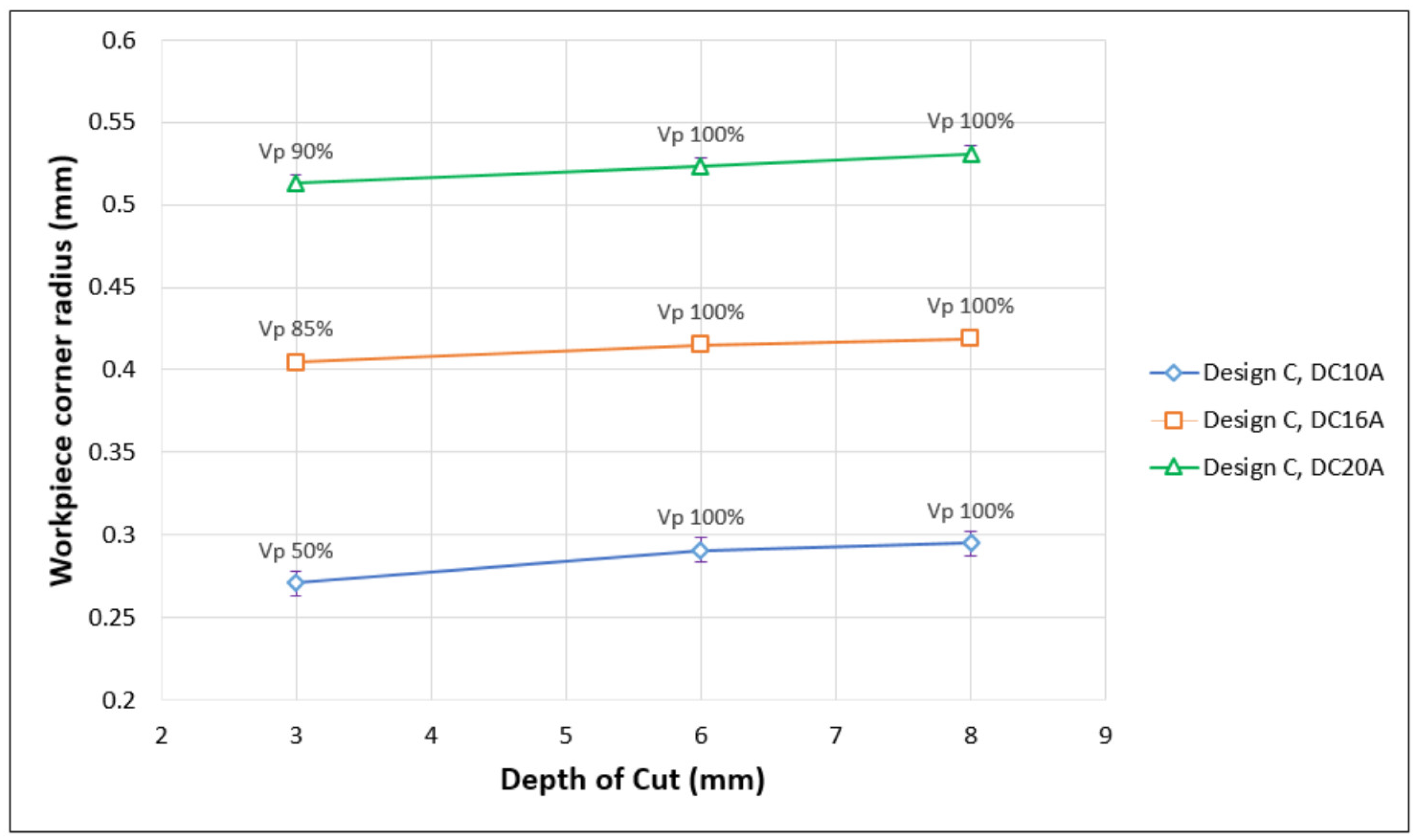
3.3. Analysis of Electrode Front-End Face Volume Design
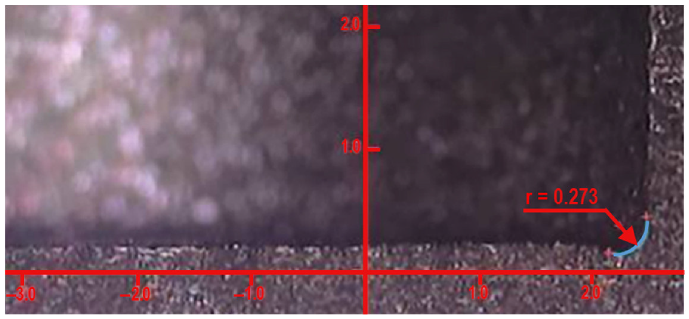
- Step 1: Choose the discharge current and electrode size, and input the machining depths of 6 and 8 mm into the regression model of workpiece corners for cylinder electrodes to obtain the workpiece corner radius;
- Step 2: Substitute the obtained workpiece corner radius value in step one into Equation (4) to calculate the cross-sectional area of A1 and A2;
- Step 3: Substitute the obtained cross-sectional areas into Equation (6) to calculate the slope . Then, substitute m into Equation (7) to calculate the coefficient ;
- Step 4: Substitute the obtained slope and coefficient from step 3 into Equation (8), and input the machining depth () to obtain the cross-sectional area of the electrode front-end face design for that machining depth:where is the electrode front-end cross-sectional area (mm2), is machining depth (mm);
- Step 5: Substitute the obtained cross-sectional area () into Equation (9) to design the width and height using w:h ratio 1:1:where is the width of the electrode protrusion, is the height of the electrode protrusion.
3.4. Analysis Correlation of Machining Parameters and Accuracy
4. Human–Machine Interface
- Input the parameters of electrode material, workpiece material, discharge current, electrode diameter, and machining depth, then choose the calculate button. The system will calculate the workpiece corner radius that will be produced with the cylinder electrode;
- Choose the compensate button. Then, the compensation page will appear, as shown in Figure 14;
- Choose the calculate button in the compensation page (Figure 14). The system will calculate the cross-sectional area of the electrode front-end face design, the size of the electrode front-end face design, the machining depth that the machine tool needs to be set, and the predicted workpiece corner radius according to the input parameters;
- Choose the save button to save all information of input parameters and compensation in CSV file format.
5. Verification Experiments
6. Conclusions
Author Contributions
Funding
Data Availability Statement
Conflicts of Interest
References
- Gnanavel, C.; Saravanan, R.; Chandrasekaran, M.; Pugazhenthi, R. Restructured review on electrical discharge machining—A state of the art. IOP Conf. Ser. Mater. Sci. Eng. 2017, 183, 012015. [Google Scholar] [CrossRef]
- Prakash, V.; Kumar, P.; Singh, P.; Hussain, M.; Das, A.K.; Chattopadhyaya, S. Micro-electrical discharge machining of difficult-to-machine materials: A review. Proc. Inst. Mech. Eng. Part B J. Eng. Manuf. 2019, 233, 339–370. [Google Scholar] [CrossRef]
- Papazoglou, E.L.; Karmiris-Obratanski, P.; Leszczynka-Madej, B.; Markopoulos, A.P. A study on electrical discharge machining of titanium grade2 with experimental and theoretical analysis. Sci. Rep. 2021, 11, 8971. [Google Scholar] [CrossRef] [PubMed]
- Ishfaq, K.; Asad, M.; Anwar, S.; Pruncu, C.I.; Saleh, M.; Ahmad, S. A comprehensive analysis of the effect of graphene-based dielectric for sustainable electric discharge machining of Ti-6Al-4V. Materials 2021, 14, 23. [Google Scholar] [CrossRef] [PubMed]
- Jain, S.; Parashar, V. Critical review on the impact of EDM process on biomedical materials. Mater. Manuf. Process. 2021, 36, 1701–1724. [Google Scholar] [CrossRef]
- Boothroyd, G.; Winston, A.K. Non-conventional machining processes. In Fundamentals of Machining and Machine Tools; Marcel Dekker, Inc.: New York, NY, USA, 1989; p. 491. [Google Scholar]
- Ho, K.H.; Newman, S.T. State of the Art Electrical Discharge Machining (EDM). Int. J. Mach. Tools Manuf. 2003, 43, 1287–1300. [Google Scholar] [CrossRef]
- Nahak, B.; Gupta, A. A review on optimization of machining performance and recent development in electro discharge machining. Manuf. Rev. 2019, 6, 2. [Google Scholar] [CrossRef]
- Das, S.; Paul, S.; Doloi, B. Assessment of the impact of bio-electrics on the textural features and recast-layer of EDM surfaces. Mater. Manuf. Process. 2020, 36, 245–255. [Google Scholar] [CrossRef]
- Walia, A.S.; Srivasta, V.; Verma, K. Modelling of surface roughness and change in out-of-roughness of tool during electrical discharge machining with cermet tool tip using machine learning. Processes 2022, 10, 252. [Google Scholar] [CrossRef]
- Beniak, J.; Krizan, P.; Soos, L.; Matus, M. Research on shape and dimensional accuracy of FDM produced parts. IOP Conf. Ser. Mater. Sci. Eng. 2019, 501, 012030. [Google Scholar] [CrossRef]
- Bhosle, R.B.; Sharma, S.B. Multi-performance optimization of micro-EDM drilling process of Inconel 600 alloy. Mater. Today Proc. 2017, 4, 1988–1997. [Google Scholar] [CrossRef]
- Cyril, J.; Paravasu, A.; Jerald, J.; Sumit, K.; Kanagaraj, G. Experimental investigation on performance of additive mixed dielectric during micro-electric discharge drilling on 316L stainless steel. Mater. Manuf. Process. 2017, 32, 638–644. [Google Scholar] [CrossRef]
- Batish, A.; Bhattacharya, A.; Kumar, N. Powder mixed dielectric: An approach for improved process performance in EDM. Part. Sci. Technol. 2015, 33, 150–158. [Google Scholar] [CrossRef]
- Zainal, N.; Zain, A.M.; Sharif, S.; Hamed, H.N.A. A study of dimensional accuracy on die sinking electrical discharge machining of Ti-6Al-4V. Indian J. Sci. Technol. 2017, 10, 1–6. [Google Scholar] [CrossRef]
- Anand, B.; Giri, A.; Mohanty, C.P.; Sharma, D. Tool wear and energy consumption optimization in EDM of Chromium tool steel. Mater. Today Proc. 2021, 43, 268–272. [Google Scholar] [CrossRef]
- Ahmed, N.; Anwar, S.; Ishfaq, K.; Rafaqat, M.; Saleh, M.; Ahmad, S. The potentiality of sinking EDM for micro-impressions on Ti-6AL-4V: Keeping the geometrical errors (axial and radial) and other machining measures (tool erosion and work roughness) at minimum. Sci. Rep. 2019, 9, 17218. [Google Scholar] [CrossRef] [Green Version]
- Mandal, D.; Pal, S.K.; Saha, P. Back propagation neural network based modeling of multi-responses of an electrical discharge machining process. Int. J. Knowl. Based Intell. Eng. Syst. 2007, 11, 381–390. [Google Scholar] [CrossRef]
- Muthuramalingam, T.; Mohan, B. Influence of tool electrode properties on machinability in spark erosion machining. Mater. Manuf. Process. 2013, 28, 939–943. [Google Scholar] [CrossRef]
- Muthuramalingam, T.; Mohan, B.; Jothilingam, A. Effect of tool electrode resolidification on surface hardness in electrical discharge machining. Mater. Manuf. Process. 2014, 29, 1374–1380. [Google Scholar] [CrossRef]
- Prasanna, J.; Rajamanickam, S. Investigation of die sinking electrical discharge machining of Ti-6Al-4V using copper and Al2O3-TiO2 coated copper electrode. Middle-East J. Sci. Res. 2016, 24, 33–37. [Google Scholar]
- Karmiris-Obratanski, P.; Zagorski, K.; Papazoglou, E.L.; Karkalos, N.E.; Markopoulos, A.P. On machining Ti6Al4V ELI with EDM by using copper and graphite electrodes: A comparison study. IOP Conf. Ser. Mater. Sci. Eng. 2021, 1037, 012003. [Google Scholar] [CrossRef]
- Ishfaq, K.; Farooq, M.U.; Pruncu, C.I. Reducing the geometrical machining errors incurred during die repair and maintenance through electric discharge machining (EDM). Int. J. Adv. Manuf. Technol. 2021, 117, 3153–3168. [Google Scholar] [CrossRef]
- Mufti, N.A.; Rafaqat, M.; Ahmed, N.; Saleem, M.Q.; Hussain, A.; Al-Ahamri, A.M. Improving the performance of EDM through relief-angled tool design. Appl. Sci. 2020, 10, 2432. [Google Scholar] [CrossRef] [Green Version]
- Liang, W.; Tong, H.; Li, Y.; Li, B. Tool electrode wear compensation in block divided EDM process for improving accuracy of diffuser shape film cooling holes. Int. J. Adv. Manuf. Technol. 2019, 103, 1759–1767. [Google Scholar] [CrossRef]
- Lo, J.S.; Jiang, C.T. Compensation method for profile deviations caused by the complex shape of electrodes in orbital electrical discharge machining. Int. J. Adv. Manuf. Technol. 2019, 103, 841–848. [Google Scholar] [CrossRef]
- Richard, J.; Giandomenico, N. Electrode profile prediction and wear compensation in EDM-milling and micro-EDM-milling. In Proceedings of the 19th CIRP Conference on Electro Physical and Chemical Machining, Bilbao, Spain, 23–27 April 2018. [Google Scholar]
- Pei, J.; Zhuang, X.; Zhang, L.; Zhu, Y.; Liu, Y. An improved fix-length compensation method for electrical discharge milling using turbular tool. Int. J. Mach. Tools Manuf. 2018, 124, 22–32. [Google Scholar] [CrossRef]
- Yu, H.L.; Luan, J.J.; Li, J.Z.; Zhang, Y.S.; Yu, Z.Y.; Guo, D.M. A new electrode wear compensation method for improving performance in 3D micro EDM milling. J. Micromech. Microeng. 2010, 20, 055011. [Google Scholar] [CrossRef] [Green Version]
- Pham, D.T.; Dimov, S.S.; Bigot, S.; Ivanov, A.; Popov, K. Micro EDM recent developments and research issues. J. Mater. Process. Technol. 2004, 149, 50–57. [Google Scholar] [CrossRef]
- Singh, H. Investigating the effect of copper chromium and aluminum electrodes on EN-31 die steel on dielectric discharge machine using positive polarity. In Proceedings of the World Congress on Engineering, London, UK, 4–6 July 2012. [Google Scholar]
- Wang, S.M.; Wu, J.X.; Gunawan, H.; Tu, R.Q. Optimization of machining parameters for corner accuracy improvement for WEDM processing. Appl. Sci. 2022, 12, 10324. [Google Scholar] [CrossRef]


| Level | Electrode Diameter (mm) | Discharge Current (A) | Depth of Cut (mm) |
|---|---|---|---|
| 1 | 10 | 10 | 3 |
| 2 | 12 | 16 | 6 |
| 3 | 15 | 20 | 8 |
| Electrode Diameter (mm) | Discharge Current (A) | Depth of Cut (mm) | Workpiece Corner Radius (mm) |
|---|---|---|---|
| 10 | 10 | 3 | 0.303 |
| 10 | 10 | 6 | 0.4 |
| 10 | 10 | 8 | 0.518 |
| 10 | 16 | 3 | 0.475 |
| 10 | 16 | 6 | 0.663 |
| 10 | 16 | 8 | 0.801 |
| 10 | 20 | 3 | 0.68 |
| 10 | 20 | 6 | 0.882 |
| 10 | 20 | 8 | 1.085 |
| 12 | 10 | 3 | 0.358 |
| 12 | 10 | 6 | 0.444 |
| 12 | 10 | 8 | 0.563 |
| 12 | 16 | 3 | 0.492 |
| 12 | 16 | 6 | 0.661 |
| 12 | 16 | 8 | 0.823 |
| 12 | 20 | 3 | 0.708 |
| 12 | 20 | 6 | 0.915 |
| 12 | 20 | 8 | 1.071 |
| 15 | 10 | 3 | 0.441 |
| 15 | 10 | 6 | 0.512 |
| 15 | 10 | 8 | 0.588 |
| 15 | 16 | 3 | 0.599 |
| 15 | 16 | 6 | 0.705 |
| 15 | 16 | 8 | 0.805 |
| 15 | 20 | 3 | 0.75 |
| 15 | 20 | 6 | 0.969 |
| 15 | 20 | 8 | 1.08 |
| Source | Sum of Square | DF | Mean Square | F Value | p Value |
|---|---|---|---|---|---|
| Model 1 | |||||
| Regression | 559,324.881 | 3 | 186,441.627 | 149.323 | 0.000 |
| Residual | 24,971.619 | 20 | 1248.581 | ||
| Total | 584,296.500 | 23 | |||
| Model 2 | |||||
| Regression | 774,040.695 | 3 | 258,013.565 | 352.784 | 0.000 |
| Residual | 14,627.263 | 20 | 731.363 | ||
| Total | 788,667.958 | 23 | |||
| Independent Variable | Unstandardized Coefficients | Standardized Coefficient | t | Sig | |
|---|---|---|---|---|---|
| B | Std. Error | Beta | |||
| (Constant) | −354.671 | 49.083 | - | −7.226 | 0.000 |
| Discharge current | 36.167 | 2.404 | 0.695 | 15.043 | 0.000 |
| Electrode diameter | 13.935 | 2.789 | 0.231 | 4.996 | 0.000 |
| Depth of cut | 49.234 | 3.510 | 0.648 | 14.026 | 0.000 |
| Independent Variable | Unstandardized Coefficients | Standardized Coefficient | t | Sig | |
|---|---|---|---|---|---|
| B | Std. Error | Beta | |||
| (Constant) | −756.444 | 57.509 | - | −13.153 | 0.000 |
| Discharge current | 57.229 | 2.760 | 0.631 | 20.734 | 0.000 |
| Electrode diameter | 11.338 | 2.135 | 5.311 | 5.311 | 0.000 |
| Depth of cut | 65.819 | 2.687 | 24.500 | 24.500 | 0.000 |
| Electrode Design | Workpiece Corner Radius (mm) | Electrode Machining Time (min) | ||||
|---|---|---|---|---|---|---|
| 10 A | 16 A | 20 A | 10 A | 16 A | 20 A | |
| Design a | 0.241 | 0.418 | 0.521 | 19.966 | 19.2 | 20.6 |
| Design b | 0.238 | 0.418 | 0.543 | 19.233 | 19.116 | 20.783 |
| Design c | 0.248 | 0.408 | 0.513 | 4.4 | 3.933 | 6.333 |
| Cylinder | 0.303 | 0.475 | 0.678 | - | - | - |
| Depth of Cut (mm) | w:h | Vp (%) | Workpiece Corner Radius (mm) | ||
|---|---|---|---|---|---|
| 10 A | 16 A | 20 A | |||
| 3 | 1:1 | 100 | 0.248 | 0.407 | 0.513 |
| 3 | 1:1 | 50 | 0.273 | 0.401 | 0.527 |
| 3 | 2:1 | 50 | 0.264 | 0.413 | 0.512 |
| 6 | 1:1 | 100 | 0.291 | 0.419 | 0.523 |
| 6 | 1:1 | 50 | 0.338 | 0.545 | 0.594 |
| 6 | 2:1 | 50 | 0.338 | 0.544 | 0.595 |
| 8 | 1:1 | 100 | 0.295 | 0.415 | 0.531 |
| 8 | 1:1 | 50 | 0.399 | 0.580 | 0.630 |
| 8 | 2:1 | 50 | 0.402 | 0.586 | 0.631 |
| Vp (%) | Workpiece Corner Radius (mm) | |||||
|---|---|---|---|---|---|---|
| Discharge Current 10 A | Circular Pit Defects | Discharge Current 16 A | Circular Pit Defects | Discharge Current 20 A | Circular Pit Defects | |
| Depth of cut = 3 mm | ||||||
| 50 | 0.273 | No | 0.401 | No | 0.527 | No |
| 60 | 0.257 | Yes | – | – | – | – |
| 80 | 0.249 | Yes | – | – | – | – |
| 85 | – | – | 0.410 | No | – | – |
| 90 | – | – | – | – | 0.511 | No |
| 100 | 0.248 | Yes | 0.407 | Yes | 0.513 | Yes |
| Depth of cut = 6 mm | ||||||
| 50 | 0.338 | No | 0.544 | No | 0.594 | No |
| 100 | 0.291 | No | 0.545 | No | 0.523 | No |
| Depth of cut = 8 mm | ||||||
| 50 | 0.399 | No | 0.580 | No | 0.630 | No |
| 100 | 0.295 | No | 0.415 | No | 0.531 | No |
| Pulse-On Time (µs) | Workpiece Corner Radius (mm) |
|---|---|
| 50 | 0.405 |
| 100 | 0.409 |
| 200 | 0.405 |
| Parameter | Value |
|---|---|
| Pulse-on time Ton (µs) | 50 |
| Pulse-off time Toff (µs) | 100 |
| Open-circuit voltage (V) | 240 |
| Open gap voltage (V) | 140 |
| Servo code | 706 |
| Work time | 0.4 |
| Electrode jump height (mm) | 1 |
| Electrode material | Cu |
| Workpiece material | SKD11 |
| Exp. Number | Electrode Diameter (mm) | Discharge Current (A) | Depth of Cut (mm) |
|---|---|---|---|
| #1 | 10 | 20 | 5 |
| #2 | 10 | 20 | 10 |
| #3 | 10 | 14 | 3 |
| #4 | 10 | 8 | 6 |
| #5 | 13 | 16 | 3 |
| #6 | 8 | 16 | 3 |
| Workpiece Corner Radius | Cylinder Electrode (mm) | Electrode Front-End Face Design (mm) | Accuracy Improvement (%) | |||||
|---|---|---|---|---|---|---|---|---|
| Exp. Number | Predicted by System | Actual Measurement | Errors (%) | Predicted by System | Actual Measurement | Errors (%) | ||
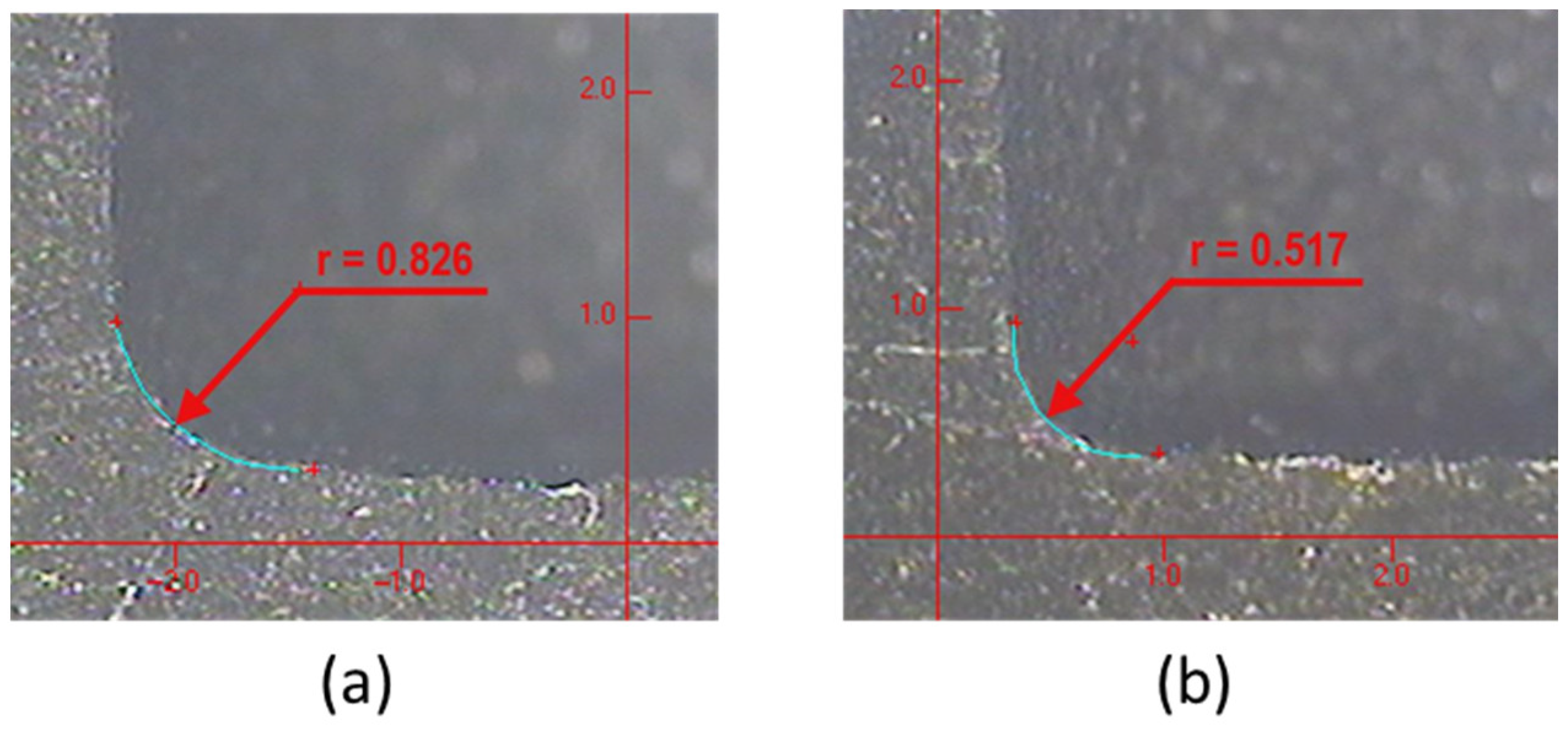
| #1 | 0.825 | 0.826 | 0.13 | 0.510 | 0.517 | 1.35 | 37.4 | |
| #2 | 1.190 | 1.184 | 0.51 | 0.525 | 0.520 | 0.96 | 56 | |
| #3 | 0.439 | 0.437 | 0.46 | 0.369 | 0.370 | 0.27 | 15.3 | |
| #4 | 0.370 | 0.371 | 0.27 | 0.272 | 0.275 | 1.09 | 25.8 | |
| #5 | 0.519 | 0.523 | 0.77 | 0.409 | 0.412 | 0.72 | 21.2 | |
| #6 | 0.468 | 0.467 | 0.22 | 0.417 | 0.420 | 0.71 | 10 | |
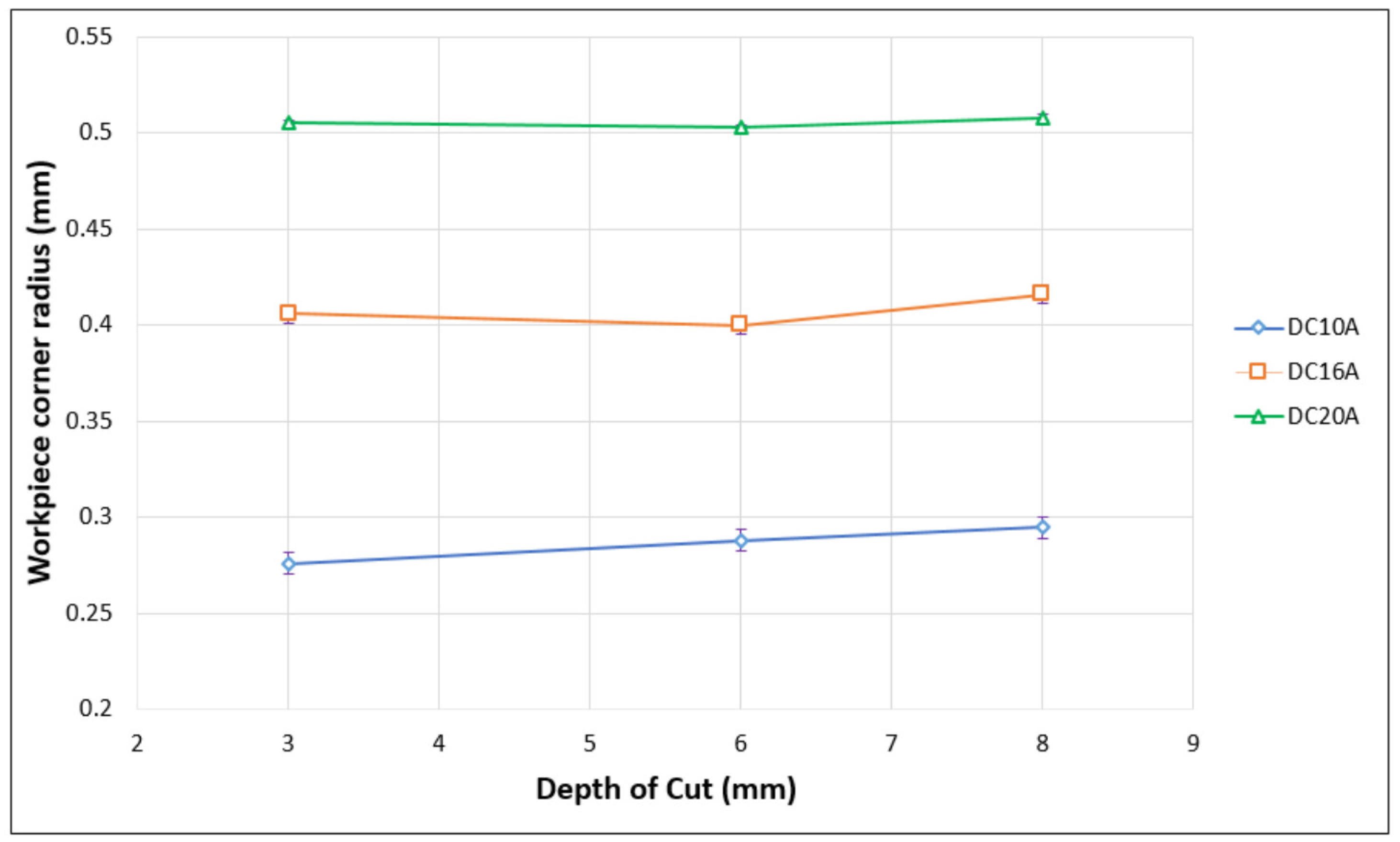
| Discharge Current (A) | Actual Measurement of Workpiece Corner Radius (mm) |
|---|---|
| 8 | 0.275 ± 0.02 |
| 10 | 0.291 ± 0.02 |
| 16 | 0.415 ± 0.02 |
| 20 | 0.523 ± 0.02 |
Disclaimer/Publisher’s Note: The statements, opinions and data contained in all publications are solely those of the individual author(s) and contributor(s) and not of MDPI and/or the editor(s). MDPI and/or the editor(s) disclaim responsibility for any injury to people or property resulting from any ideas, methods, instructions or products referred to in the content. |
© 2023 by the authors. Licensee MDPI, Basel, Switzerland. This article is an open access article distributed under the terms and conditions of the Creative Commons Attribution (CC BY) license (https://creativecommons.org/licenses/by/4.0/).
Share and Cite
Wang, S.-M.; Peng, J.-K.; Gunawan, H.; Tu, R.-Q.; Chiou, S.-J. A Novel Electrode Front-End Face Design to Improve Geometric Accuracy in Electrical Discharge Machining Process. Metals 2023, 13, 1122. https://doi.org/10.3390/met13061122
Wang S-M, Peng J-K, Gunawan H, Tu R-Q, Chiou S-J. A Novel Electrode Front-End Face Design to Improve Geometric Accuracy in Electrical Discharge Machining Process. Metals. 2023; 13(6):1122. https://doi.org/10.3390/met13061122
Chicago/Turabian StyleWang, Shih-Ming, Jin-Kai Peng, Hariyanto Gunawan, Ren-Qi Tu, and Shean-Juinn Chiou. 2023. "A Novel Electrode Front-End Face Design to Improve Geometric Accuracy in Electrical Discharge Machining Process" Metals 13, no. 6: 1122. https://doi.org/10.3390/met13061122