Review

Ultrasonic Assisted Machining Overview: Accessing Feasibility and Overcoming Challenges for Milling Applications

1
Department of Mechanical Engineering, University of Minho, Campus of Azurém, 4800-058 Guimarães, Portugal
2
CMEMS—UMinho, University of Minho, Campus of Azurém, 4800-058 Guimarães, Portugal
3
LABBELS—Associate Laboratory, 4800-058 Guimarães, Portugal
*
Author to whom correspondence should be addressed.
Metals 2023, 13(5), 908; https://doi.org/10.3390/met13050908
Submission received: 30 March 2023 / Revised: 4 May 2023 / Accepted: 5 May 2023 / Published: 7 May 2023
(This article belongs to the Special Issue Green Manufacturing for Metallic Materials)

Abstract

:
Machinability, along with its associated facets, is a critical parameter that ultimately determines the cost of machining. Its optimization, however, is inherently limited by the current technology. To surmount such limitations, novel alternative machining technologies, such as Ultrasonic Assisted Machining (UAM), have emerged. The present study introduces UAM, the technology’s underlying principles, and general considerations for vibration application (harmonic waves, eigenfrequencies, resonance). The influence of ultrasonic application on the key parameters of conventional machining processes is studied and relevant research data are presented to support UAM benefits. Following, a comprehensive kinematic examination of vibration application to the milling process is conducted, accounting for various possible vibration modes. A detailed analysis of the requisite system components and their technical specifications is presented, followed by identifying common issues within such systems. Solutions for the identified limitations are proposed, acting as design guidelines for future technological advancements. Finally, based on the conducted research, conclusions are drawn and future directions for UAM are suggested.

1. Introduction and General Considerations

The cost of machining a material is related to the machining parameters, tool cost, generated cutting forces, and the surface quality of the machined piece. Optimizing these factors can reduce the machining time by increasing the material’s overall machinability. This shifting will depend on straightforward aspects, such as the selected machining process, and characteristics such as needed tools, machining equipment, and specifications that will rely on the material’s mechanical properties [1,2].
There is a growing interest in the machining of complex materials due to their excellent physical and chemical properties [3], making them exceptional alternatives in several fields of modern society, such as aerospace [4,5,6,7], automotive [8,9,10,11], and medical industries [4,10]. The enhanced properties of these materials make them challenging to machine effectively. Thus, machinability plays a crucial role in their machining. However, a bottleneck where further enhancements are no longer possible is inevitable even if every aspect of a machining process is completely optimized, distinctive to the technique’s specific characteristics.
Furthermore, since economics is one of the most significant driving forces of constant technological evolution, with the machining industry primarily targeting cost reduction, alternative technologies arise that aim to transcend such limitations, as is the case with ultrasonic machining.
The milling process of metals is one of the most widely used conventional machining operations for obtaining complex geometries and dimensional characteristics. Implementing ultrasonic technology in this operation is specifically challenging, as there is a lack of theoretical research [7] on dynamics and cutting characteristics for both predictive theories and quantitative models that would allow machining processes to be optimized even further, specifically for complex materials [7,12,13,14].
Therefore, the focus of this paper is to clarify the underlying principles of the technology and to propose solutions for the main identified limitations in the application of ultrasonics to the conventional milling process.

1.1. Machinability and Project Optimization

Machinability denotes how easy it is to cut a material and constitutes the pivotal factor in machining efficiency. This property relies on the operation’s parameters and depends on the material’s mechanical and thermal properties [15].
The main machinability-affecting factors include the selected machining process, the utilized machining station and cutting tools, the employed cutting parameters, the material and shape of the workpiece and its fixation method, the used cutting fluid, and the process chain optimization [16,17,18,19].
Defining an adequate station for the selected machining process is a critical factor, as the operation type must be compatible with the desired cutting process. The selection of cutting tools should be based on the material and properties of the workpiece, and the cutting routine should include minimal tool changes since tool changes affect machining time. A reverse analysis can be performed in such a way that machinability directly influences tool life, surface quality, cutting forces, and the chip-forming process. Machining cost determines the machining efficiency, as project optimization is related to the economic facet of the manufacturing industry. Undeniably, the total production time will profoundly affect the machining cost.
Machining time benefits from increased cutting parameters. Consequently, the longer it takes to cut a material, the higher its machining cost is. However, carefully selecting the cutting parameters is critical, given that inadequate, exaggerated values may promote premature tool wear, surface imperfections on the workpiece, and higher required machining power. The increase in factors such as tool cost with increased cutting speeds becomes evident as materials with enhanced properties require more expensive tools (e.g., coated tools which increase cutting efficiency [20]). Moreover, tool replacements will be more frequent as the wear increases.
Considering these factors, the project optimization scope is fundamentally limited by its individual parameters, and a plateau is reached that can solely be surpassed with the development of new techniques for machining complex materials, in which the cutting efficiency would, conventionally, be reduced. It is at this point that alternative machining technologies come in.

1.2. Complex Materials and Alternative Machining Technologies

The development of alternative machining technologies aims to overcome inherent obstacles in conventional machining, as traditional machining techniques show a bottleneck in improving machining performance, as stated in the previous section.
Although several distinct methods have been developed over the years, they all share the same purpose: pushing the limits of optimal solutions.
Although alternative machining methods are not limited to complex materials, they are usually used to handle them. Some examples of these include titanium alloys, Inconel (nickel-based superalloys), composites, and ceramics [3,10,12,21,22].
Several application fields use these materials for their specific properties (e.g., excellent strength-to-weight ratio and improved heat resistance [8,23]), including the aerospace and aeronautic industries (Ti6Al4V in lightweight engine structures [4,5,8,10], Inconel in turbomachinery components [24], and CFRP in structural components [25,26]).
These materials can also be found in the automotive (e.g., ceramics in bearings, rotary parts, and brake pads) [8,9,10,11] and medical industries (e.g., ceramics for tooth implants) [4,10], as well as in the energy, electronics [9], and optical [5,8] fields, along with general usages in precision machining to produce microscale components [12].
Complex machining materials require specialized tools and techniques to machine effectively. Poor machinability, which leads to increased cutting forces and surface roughness, low machining accuracy, and rapid tool wear, makes these materials too demanding for conventional machining technologies, where the key requirement is productivity [4,27].
Overall, cost-effective machining technologies that improve the cutting efficiency of these materials are required for a profitable cutting process. In addition, the manufacturing of structural components continues to face challenges in finding effective additive manufacturing methods that can match the performance of classical subtractive alternatives. These techniques often exhibit low fatigue resistance, making them unsuitable for critical applications, such as in the aeronautical industry. Consequently, the subtractive manufacturing method remains the focal point of the machining industry for developing new technologies and optimizing existing ones.

2. Ultrasonic Assisted Machining Overview

The application of ultrasonic vibration in machining processes has been well-present for over 60 years [6,7,9,28,29]. Although the first patent was only awarded to L. Balamuth in 1945 [9], there are records of academic research on this matter dating as far back as 1927, with the submission of a paper by R. W. Wood and A. L. Loomis [7,9].
The ongoing development of the machining industry has facilitated the emergence of a wide range of ultrasonic systems, which are particularly effective machining techniques that produce minimal residual stress on the workpiece’s surface, consisting of a promising option for machining brittle materials [9]. Nonetheless, initial developments in ultrasonic machining were associated with low material removal rates, and mainly used as a finishing operation [12].
The machining evolution has ultimately resulted in various designations for the technology. Nevertheless, ultrasonic machining has become the most widely used variation since the 1950s [9]. The application of this technology to traditional machining processes escapes the rule. Thus, two groups are formed depending on the type of applied vibration: Conventional Ultrasonic Machining (USM), involving the practice of ultrasonic impacts on workpieces of brittle materials carried out by a medium of abrasive slurry, and Ultrasonic Assisted Machining (UAM), consisting in the application of ultrasonic vibrations to conventional machining processes.
Applying ultrasonic vibration to conventional machining processes started with turning operations and can be traced almost as far back as the first ultrasonic machining technologies. The consequent employment of other traditional machining techniques has increased with the exponential growth of the machining industry, paced by the evolution of ultrasonic transducers and horn structures. UAM systems are the evolution of conventional USM techniques [6,12,14,28], where high-frequency vibration is applied to one or more components of a machining operation instead of relying on an abrasive mixture for material removal. A traditional tool with cutting edges is used, while applied vibration causes discontinuity in the tool–workpiece interaction, increasing the efficiency of the process in question [7,11,27].
Vibration can be applied either to the cutting tool, namely, the Actuated Tool System (ATS), or to the workpiece, namely, the Actuated Work System (AWS), corresponding to one of the main system-defining characteristics [14,27,30]. Vibrating tool systems, the most common alternative, are often studied based on the motion of the cutting tooltip. The discontinuity between the two surfaces consists of four basic movements (Figure 1) repeating cyclically with the applied frequency: approach, contact, immersion, and back off.
The machining industry uses UAM mostly in turning and drilling processes, where better performance is consistently reached [13,31]. Nonetheless, comprehension of this technology is limited, especially for the milling process, where there is scarce investigation on the technique’s dynamics and cutting characteristics.
Several degrees of vibration—vibration modes—can be applied to a system, either to the tool or the workpiece. UAM systems are purposely divided according to the vibration mode. As previously outlined, three categories arise, including vibration in one, two, or three dimensions [12,14,32].
A historical perspective of the first developments in UAM for distinct vibration modes is provided in Figure 2.
Applying vibration in a single direction is a less challenging approach than designing a system comprising two or more vibration axes. Accordingly, 1D UAM systems have preceded 2D and 3D alternatives for an extended period. In 1D UAM systems, the tool can either vibrate in the cutting direction or any other direction perpendicular to it. For example, an axial vibrating tool will coincide with the feeding direction in the drilling process, while being perpendicular to the feeding motion in a milling operation. This superimposed movement will occur harmonically in a linear path [12].
Introducing a second vibration direction will generate an elliptical motion at the tooltip, while a third vibration axis will result in a spatial elliptic curve [22].
Multi-axial vibration systems have shown to further enhance the attained advantages of 1D systems, particularly regarding improvements in surface finish quality, cutting force reduction, and tool life extension [22,32]. However, current challenges for these system types include stabilizing control signals and improving transducer efficiency [32].

2.1. Influence on Key Machining Parameters

The interest in UAM derives from the distinct benefits this technology offers over diverse operating conditions, machining parameters, and tool and workpiece materials. The ultrasonic vibrations aid in breaking the workpiece material, creating a more favorable cutting environment by reducing the cutting resistance.
The intermittent contact promotes easier chip separation, breaking, and extraction from the cutting area, preventing the clustering of generated particles in tooling surfaces and reducing friction between the tool and the workpiece [4,28]. The heat generation decreases, reducing tool wear (leading to longer tool lives) and the workpiece surface roughness (leading to an improved surface finish). Other advantages include minimal burr formation and a higher critical value for the depth of cut in the ductile regime machining of brittle materials [6,7,11,12,14,22,32]. UAM enhances part selection flexibility and the quality of said parts, increasing dimensional accuracy and machining productivity [4].
The most relevant advantage of the process is reducing cutting forces, in some cases, by over 50% [13,36]. The intermittent contact between the tool and the material lowers the Tool–Workpiece Contact Ratio (TWCR), and the cyclic cutting interruption shortens the effective cutting time. In addition, this process eases the heat dissipation between cycles of interrupted cutting, preventing excessive heat accumulation, thermal burns, and physical/chemical property changes in the workpiece [5,12,27].
Lower cutting forces minimize the formation of thermal cracks and plastic deformation in the workpiece and improve surface integrity due to the arrangement of the component’s microstructure (lower residual stresses). Non-continuous chip formation and reduced subsurface cracks enhance the uniformity of the cut, resulting in a smoother machined surface with reduced roughness [5,12]. Reduced tool wear is associated with decreased adhesion of workpiece material to the cutting tool, meaning fewer particles remain to cause secondary damage to the machined surface [12].
The enhancements in machining complex materials are supported by experimental research regarding ultrasonic techniques, in which the increase in the values of employed parameters such as spindle speed and vibration amplitude tend to accentuate the attained benefits further [3,5,21,22,27,37,38].

2.2. Underlying Principles and General Considerations

The ultrasonic designation comes from the implied vibration frequency values in the audio frequency spectrum. An ultrasonic transducer converts the electrical energy into mechanical vibrations that are transmitted to the component. The vibration frequency belongs in the ultrasonic range, beyond the upper limit of human hearing, generally over 20 kHz [28,32]. The audio frequency spectrum is depicted in Figure 3, in which the ultrasonic domain can be observed next to the acoustic range.
The ultrasonic wave propagates through different mediums, provoking infinitesimal displacements of the molecules of the transposed medium and disturbing their equilibrium state. Intensity, determined by the ultrasonic frequency, and vibration amplitude, which sits in the micron range, describe the wave and quantify the power transmitted through a unit cross-section area [28]. Since vibration is transmitted to the tool or the workpiece, the applied frequency value generally coincides with one of its natural frequencies (or eigenfrequencies).
An eigenfrequency is a characteristic frequency in which a system naturally oscillates when disturbed from equilibrium without external force interference. Vibration amplitude is amplified if an applied external frequency coincides with one of the system’s eigenfrequencies. This phenomenon is called resonance, leading to more energy-efficient systems [14]. The increased efficiency is due to the system’s harmonic response to the applied sinusoidal load, as the damping ratio tends to zero. Theoretically, if damping was non-existent, amplitude at resonance would be infinite.
Non-resonant systems also operate in a continuous frequency range, though with values below the ultrasonic domain, with a working amplitude higher than the resonant type [14,32]. Besides being energetically more efficient, resonant systems operate far above specific natural frequencies that could cause uncontrolled resonance. The purpose of applying vibration is solely to enhance the cutting process.
System stability will fundamentally depend on parameter control. As frequency takes on immense values, amplitude belongs in the micron range, generally below 50 μm [10,27,39,40]. Regardless of resonance resulting in maximum displacement, vibration amplitude will ultimately be limited by the relationship between the excitation and mechanical response of the transducer, adding to the difficulty of controlling the tool trajectory due to phase lag [14]. Such limitations increase the importance of energy efficiency in resonant systems.
In ATS systems, the transducer generates mechanical vibrations and the sonotrode, also referred as booster or horn, transmits them to the tool. The latter vibrates according to the imposed direction(s). Consequently, while in ATS systems the optimization of the material removal rate is largely dependent on both the tool and the horn, directly impacting the vibration environment, AWS alternatives will rely on a much more challenging design, as the practicality of tuning the system specifications to the cutting tool is greatly superior when compared to actuating on the workpiece. AWS methods benefit from workpieces with thinner walls, given the nature of the acoustic transmission, making ATS setups more common, as they do not depend on workpiece configuration [7].

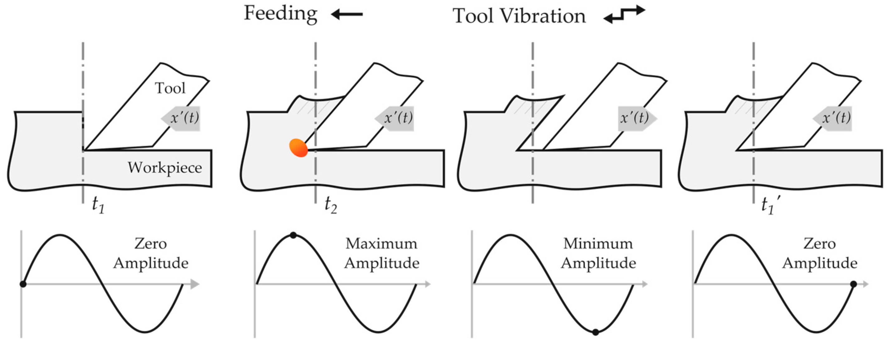
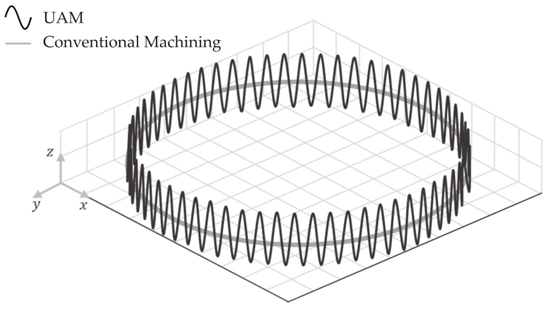
2.3. Milling Process Kinematic Analysis

Combining the applied harmonic load with the tool’s rotating motion during the cutting process results in a complex tooltip movement. For 1D UAM systems with axial tool vibration, in operations where the tool is rotated, torsional vibration is present at the bottom of the cutter, resulting from the conjunction of the imposed vibration and the rotation movement. Depending on the tool’s geometry, this can also reduce cutting forces [41].
A kinematic analysis of UAM milling allows for the comprehension of the tool’s movement. Nonetheless, torsional vibration is neglected in the present study due to its minimal influence. The kinematic study addresses a 1D ATS UAM system, being the most simple and usual application type of vibration to the milling operation.
Since vibration can be applied to three directions in a milling operation, Figure 4 includes a schematic representation of the three cases. These refer to vibration in the primary cutting (feed), crossfeed, and depth of cut directions, represented by the x, y, and z axes, respectively.
When vibration coincides with the feed direction, only the x axis is studied. Considering the four stages depicted in Figure 1, the tool’s position can be studied according to the vibration amplitude. Such a scenario is presented in Figure 5.
The motion equation of the system for the analyzed axis is shown in Equation (1), where  x  corresponds to the tool’s displacement,  A  to vibration amplitude,  f  to vibration frequency,  v f  to the feed rate, and  t  to time:
x t = A   s i n   2 π f t + v f t
Following, through differentiation, velocity can be defined by Equation (2) as:
v t = x t = 2 π f A   c o s   2 π f t + v f
Under these circumstances in which movement occurs in a single direction, there will be a critical value for the feed rate above which the tool will permanently contact the work surface, given by Equation (3):
v f   c r i t = 2 π f A
UAM advantages derive from the interrupted cutting motion, which will only manifest if the applied feed rate is below this critical value.
Alternatively, if  v f v f   c r i t , the cutting process becomes continuous, similar to that of conventional cutting. Nonetheless, the harmonic variation of the relative velocity between the tool and the workpiece will still occur [12].
The horizontal speed ratio, HSR, can be defined as the ratio between the feed rate  v f  and the critical feed rate, as shown in Equation (4) [12,14].
H S R = v f v f   c r i t
Continuous cutting will occur for HSR ≥ 1. Moreover, the distance travelled by the tool between two equivalent points in a successive vibration cycle, represented by  d P , can be defined by the ratio of the feed rate  v f  to the vibration frequency  f , as shown in Equation (5):
d P = v f f
The time variables that define the interrupted contact between the tool and the workpiece are instants  t 1 , when the tool contacts the surface of the uncut material, and  t 2 , when such contact is terminated. These can be observed in Figure 5.
The time frame between these instants is the portion of a single vibration cycle in which material removal happens, being designated as the duty cycle, represented by DC. When related to the harmonic period  T  or its reciprocal frequency, it can be defined by Equation (6):
D C = t 2 t 1 T = f t 2 t 1
If vibration is applied perpendicular to the feed direction, whether coinciding with crossfeed or with the direction of the depth of cut (axial tool direction), the analysis requires the division of the tool’s movement between the two corresponding coordinate axes. Movement in direction  x  is now only defined by the feed rate  v f , as shown in Equation (7):
x t = v f t
The harmonic movement of the tool will be defined either in direction y, for vibration in the crossfeed direction, or z, for vibration in the tool’s axial direction. For systems where vibration coincides with the crossfeed direction  y , the harmonic movement of the tool is defined by the expressions presented in the system of Equation (8):
x t = v f t y t = A   s i n   2 π f t
As for axial vibration, in the depth of cut direction  z , respective expressions are shown in the system of Equation (9):
x t = v f t z t = A   s i n   2 π f t
Velocity in these cases can also be defined by the differentiation of the above presented equations, in systems (8) and (9), for crossfeed and depth of cut directions, respectively.
Figure 6 shows the tooltip’s displacement for different 1D UAM systems vibrating in the three coordinate axes.
Considering the abovementioned analysis, Figure 7 depicts the critical case of an axial vibrating (z-direction) ATS milling system. A schematic representation of the system is given by adding a randomly selected point, P, within the tool’s cutting edge.
The spatial trajectory of the selected point within a single tool rotation with vibration should also be considered for comparison with an equivalent point without the applied harmonic wave. Figure 8 represents this scenario.
Even though the established system of Equation (9) depicts the feed rate and the harmonic wave movement, it is crucial to include spindle rotation in the analysis.
Considering  ω s  as the angular velocity of the spindle, hybrid movement is generated in the tooltip. This parameter is critical as no cutting action occurs if the tool does not rotate. Consequently, the tool’s motion can be defined by including this parameter in the previous analysis, as shown in the equations presented in the system of Equation (10) [10]:
x t = v f   t + R   s i n ω s t y t = R   c o s ω s t z t = A   s i n 2 π f t
Parameter  R  is the radius of the tool.
The definition of velocity over the three coordinate axes can be achieved by differentiating the above-presented expressions, as shown in the system of Equation (11), concluding the kinematic study.
x t = v f + R ω s   c o s ω s t y t = R ω s   s i n ω s t z t = 2 π f A   c o s 2 π f t

3. Comprehensive Analysis of Required Components

The following analysis focuses on a resonant 1D ATS UAM system for milling, in which the tool is driven harmonically in one dimension, coinciding with its axial direction.
The design of the system includes an ultrasonic generator, which generates high-frequency electrical energy, acting as a power supply, a transducer, a sonotrode, and a vibrating cutting tool.
The efficiency of the vibrating system depends on ensuring consistent contact among all components involved, reducing any potential electrical and mechanical losses [28]. The cutting tool must be perfectly aligned at the end of the sonotrode, which acts as the tool holder [12,32].
Figure 9 shows a general representation of the components of a 1D ATS UAM system.

3.1. Ultrasonic Generators

An ultrasonic generator is used to convert the standard power of the network (120–240 V, 50/60 Hz) into AC electric energy at the desired ultrasonic frequency, within its range of working operation. The ultrasonic generator operates in the discrete frequencies required by UAM systems, reaching values up to 40 kHz in the ultrasonic range, consisting of high Q resonant systems [12]. However, as the applied frequency depends on the design of the system, and given the risk of non-optimal working frequencies due to possible setup errors and tool wear, some resonance following generators have been able to automatically tune the output frequency to match the natural frequency of the assembly. These also minimize acoustic energy loss and heat generation, possibly including safety features [9].

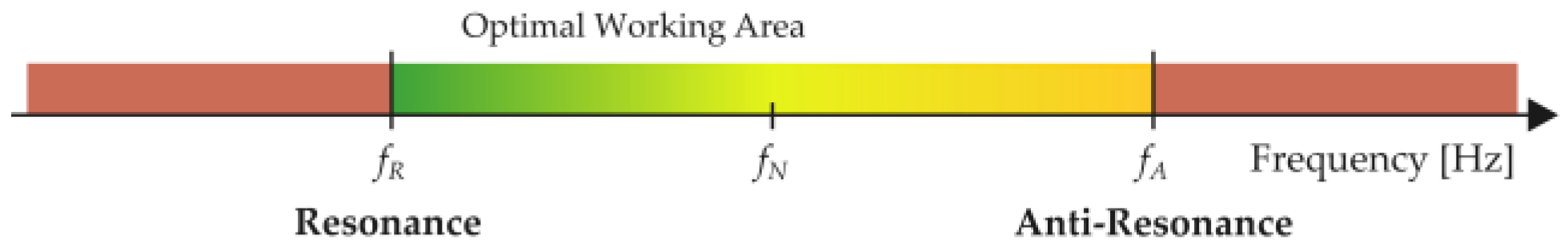
3.2. Piezoelectric Transducers

Once the frequency is converted to the system’s desired values, the transducer will begin to function. The electrical energy is transformed into a reciprocating harmonic high-frequency, low-amplitude mechanical motion. For ultrasonic industrial applications, transducers are generally piezoelectric or magnetostrictive. A disadvantage of the latter is their reduced working efficiency (under 55%), due to significant losses in the form of generated heat [9].
Piezoelectric (PZT) transducers are more popular in UAM systems. Besides having a higher working efficiency (over 90%), they achieve higher frequencies and present better temperature stability, smaller size, easier construction, and more extended durability [9].
The piezoelectric effect is the ability of materials to generate an electrical charge when mechanical stress is applied to them. Inversely, as PZT materials are smart materials, their shape will change as they expand or contract, depending on the polarity, generating mechanical energy. This is known as the converse piezoelectric effect and is the working principle of a PZT transducer [42,43].
Multiple PZT discs (or actuators) are stacked inside the transducer to achieve high working frequencies without the need for active cooling, recurring to a phased actuator activation sequence in which each disc works at a lower frequency than the higher output frequency value [12].
Every transducer is designed to function at a determined nominal working frequency, given by  f N . Nonetheless, this frequency value will come with a small tolerance.
The working interval in which the transducer’s frequency can vary is studied concerning its electrical impedance, being fundamentally limited by its resonant and anti-resonant working regimes. The resulting impedance-frequency function is the transducer’s impedance curve, represented by |Z|.
The peak minimum impedance point corresponds to the resonant regime, while the maximum peak impedance refers to the anti-resonant regime. Figure 10 shows a general representation of the curve.
An electromechanical analogy relating electrical current to force and voltage to velocity can be established. Given the nature of the corresponding circuit, it can be understood that the transducer can deliver maximum output force (or pressure) and relatively low velocity at resonance. This regime would be the theoretically most effective frequency at which the transducer could operate, resulting in maximum vibration amplitude. At the system’s anti-resonant regime, maximum output velocity and minimum output force will be delivered (minimum vibration amplitude) as the transducer’s mechanical and electrical components are not in phase.
Frequencies below the resonant frequency (given by  f R ) and above the anti-resonant frequency (given by  f A ) correspond to a purely capacitive behavior of the transducer, with current leading the voltage by a phase angle  ϕ . Between analyzed nodes, however, the transducer’s behavior is purely inductive, allowing all energy to be used for vibration generation.
The transducer is designed to work within the inductive interval, where its energy efficiency is maximum. Outside of this range, the temperature increases (reactive energy), leading to system failure, as current needs to flow for voltage to be established. The applied current intensity and voltage are regulated at the ultrasonic generator, and the input power controls the force that the transducer provides.
While in theory, a system would perform best at the analyzed resonant frequency, a small frequency deviation can cause the transducer to operate in its capacitive zone, leading to system failure. Hence, the optimal working frequency area for the transducer is shown in Figure 11, regarding a color-coded system, with red indicating the least favorable, and green indicating the most favorable scenarios.
To ensure the optimal performance, the system needs to be tuned so that its eigenfrequency coincides with the transducer’s inductive zone while approaching resonance for amplified vibration efficiency.

3.3. Sonotrode Considerations

There is a deviation in the UAM field regarding the designation of the vibration-amplifying components and consequent cutting tool assembly. Maximum vibration amplitude values vary harmonically depending on the direction in which the oscillation is applied, system geometry, and consequent energy absorption. The variation in 1D ATS type setups also occurs in the axial direction.
The resulting harmonic profile is determined by the location of the nodal points (nodes and antinodes), corresponding to minimum and maximum displacements, respectively. The nodal points quantify the energy the system absorbs or transfers to the tool. The transducer’s piezoelectric membranes coincide with the location of a node, so in theory, there is no displacement at this point under working conditions.
Amplitude values at the face of a transducer are insufficient to achieve reasonable cutting rates, stating the need for an amplifying component to be designed [9]. Depending on the required application, using a booster component may be unnecessary. Sometimes, the sonotrode is designed to comprise the booster’s effect.
While component length determines the amplitude variation profile frequency, the amplitude value change is determined by the variation of the specified component’s outer diameter D. Maximum amplitude increases with a reduction in diameter.
The design requirements result from the maximum desired vibration amplitude at the free end of the tool [9]. Thus, correct design and optimization of the sonotrode is a critical demand, considering both wavelength  λ  and outer diameter D.
Nonetheless, a thorough analysis should be conducted for each case to determine the most appropriate design. Moreover, material choice is also critical in sonotrode design, as good acoustic transmission properties and high fatigue resistance under working conditions are required.

4. Identified Issues

Not only the complexity of the technology makes the design of UAM systems a challenging task, but any project will also be fundamentally limited by the hardware structures and PZT materials’ capacity [32]. Moreover, excessive amplitude values will increase internal stresses in both the tool and sonotrode, reducing their service life if the fatigue strength is surpassed [27].
In addition, there are recognized concerns that persistently impede the optimal functionality of these systems, specifically:
  • Difficulty in transmitting energy from the static generator to the rotating system;
  • Variable nodal points and localized heating issues due to suboptimal tool fixation methods.

4.1. Energy Transfer Method

The issue of energy transfer is intricately linked with designing a compact ATS setup, as it demands a compact and functional system. The goal is to balance the practicality of the selected energy transfer mechanism and the desired stability of the system, which is essentially contingent on the number of employed components, their corresponding interconnections, and the overall system size.

4.2. Tool Fixation

A large number of system components leads to an increase in the number of connections between them and the number of contact points. Therefore, all fastening joints in the ultrasonic system must adhere to strict tolerances. Any deviation may result in localized heating when high-frequency values are achieved. Compromised system stability due to the large number of required components may also affect the overall system’s efficiency.
The tool fixation method is a critical factor in designing these systems. Collet chuck holders are unsuitable for UAM applications. The mechanical properties of the materials used in their construction are often incompatible with the working conditions, leading to local heating of the contact zone between the collet and the cutting tool. The affected surfaces gradually become more compliant and absorb more energy, reducing vibration frequency and damping the contact. Consequently, the resulting nodal points of the system vary, making it challenging to project a system with optimal resulting amplitude values at the free end of the tool. Thus, alternative tool fixation mechanisms must be explored.

4.3. Proposed Solutions

A potential solution for the energy transfer method could be the utilization of a slipring, which comprises an electromechanical element that converts the electrical power and signals from a stationary to a rotating component or system. The operational principle of this component stems from the two constituent parts, namely, the stator (exterior, stationary portion that links to the generator) and the rotor (interior, rotating portion that connects to the transducer). The electrical linkage between the two segments is established via a series of conductive rings. Therefore, a slipring would ease the transfer of the harmonic wave from the ultrasonic generator to the piezoelectric transducer without causing cable-related difficulties during spindle rotation.
Regarding tool fixation, one solution to the tool holder problem may be using a shrink-fit tool holder, recurring to the material’s thermal expansion for tool insertion. A holder of this kind would provide excellent clamping force and rigidity due to the tight fit between the holder and the tool shank, ensuring the efficient transmission of ultrasonic vibration to the cutting tool. The high accuracy and repeatability that characterize this element are essential in achieving consistent machining results. Additionally, being designed with the sonotrode as a single piece would reduce the number of components and minimize the number of joints and points of contact in the system. A single component for both applications would aid in system uniformity and stability, which is crucial for the precision and accuracy needs of the machining process.

4.4. Additional Considerations

The intensity of the tool–workpiece contact will be amplified with the system’s overall length, as torque τ is equal to the product between applied force to the tool flanks F and the lever’s arm length d, which in this context refers to the distance between the zone where vibration is generated and where the tool–workpiece contact occurs.
Greater distances lead to greater generated torque values. Longer overall system length and longer tool shanks can increase the likelihood of tool deflection beyond acceptable values, causing geometrical issues and potential accelerated tool wear.
In systems where the vibration and feeding directions coincide, employed vibration will further amplify deflection, influenced not only by the system’s length but also by the employed depth of cut (DOC). As for axial vibrating 1D ATS systems, greater DOC values will intensify tool wear by abrasion due to the combined effect of oscillatory movement and friction between tool and workpiece surfaces.
Accordingly, the tool’s length must be selected while considering the overall length of the system, which is intrinsically imposed by the number of involved components. The objective is to ensure that the tool is as short as possible while being long enough to be capable of performing the desired machining operation. Minimizing system deflection is crucial in achieving maximum system efficiency.

5. Conclusions

The significance of machining processes and their operations in the modern industry cannot be overstated, as these methods are fundamental to producing countless components for specific applications. Despite their importance, however, the constant technological evolution in diverse areas creates a bottleneck to applying these technologies, as emerging materials with superior mechanical properties pose significant challenges to conventional machining processes. Alternative machining technologies offer a viable solution to overcome these limitations.
UAM presents several advantages over traditional machining methods, including improved machining parameters, reduced cutting forces, longer tool lives, and improved surface finish. Its ability to facilitate chip breaking and reduce burr formation is useful in precision manufacturing applications, and its potential for machining difficult-to-machine materials makes it a promising alternative in machining technologies.
Specifically, UAM presents several benefits in machining difficult-to-cut materials, such as titanium alloys, Inconel, composites, and ceramics, consistently used in advanced fields such as the aeronautics and aerospace industries.
Despite the lack of research on the topic of UAM for milling applications, this presents an excellent opportunity to explore and advance this technology. The potential for improved machining efficiency by applying engineering concepts and developing viable technologies is interesting from an academic and engineering standpoint and fundamental for practical applications. However, a comprehensive understanding of the complex nature of vibration application is fundamental to any UAM system development.
The presented theoretical study proposed solutions to address the consistent issues encountered in UAM systems during milling operations. Utilizing a slipring for energy transfer presents practical and compact UAM system design opportunities. Furthermore, integrating a shrink-fit holder and sonotrode into a single piece can significantly improve system stability and efficiency while benefiting from the advantages of this tool fixation method. These proposed solutions can contribute to the advancement of UAM technology and its implementation in various industries.
The development of numerical models relative to the study of the influence of vibration applied to the characteristic tool movement of conventional cutting processes can yield valuable kinematic insights crucial for designing an efficient UAM system. Further studies on this matter must be conducted prior to system conceptualization.
Nevertheless, the advancement of ultrasonic technology in the machining field should involve the implementation of the presented guidelines for manufacturing and experimental testing of systems, providing significant data for further improvements.
Further optimization could also include designing frequency regulation systems to enable tuning and maintaining optimal resonant frequency values, thereby enhancing the machining advantages of the technology.
In general, it is anticipated that the current review will serve as a valuable resource in the process of selecting and fine-tuning ultrasonic milling parameters to enhance the quality of produced components.

Author Contributions

Conceptualization, H.M. and H.P.; Methodology, H.M., Validation, H.M. and H.P.; Formal Analysis, H.M. and H.P.; Investigation, H.M.; Resources, H.P.; Data Curation, H.M.; writing—original draft preparation, H.M.; writing—review and editing, H.M. and H.P.; Supervision, H.P.; Funding acquisition, H.P. All authors have read and agreed to the published version of the manuscript.

Funding

This work was supported by Portuguese FCT under the project UIDB/04436/2020.

Data Availability Statement

Not applicable.

Conflicts of Interest

The authors declare that there is no conflict of interest.

References

  1. Aamir, M.; Davis, A.; Keeble, W.; Koklu, U.; Giasin, K.; Vafadar, A.; Tolouei-Rad, M. The Effect of TiN-, TiCN-, TiAlN-, and TiSiN Coated Tools on the Surface Defects and Geometric Tolerances of Holes in Multi-Spindle Drilling of Al2024 Alloy. Metals 2021, 11, 1103. [Google Scholar] [CrossRef]
  2. Tolouei-Rad, M.; Aamir, M. Analysis of the Performance of Drilling Operations for Improving Productivity. In Drilling Technology; IntechOpen: London, UK, 2021. [Google Scholar] [CrossRef]
  3. Wang, J.; Shimada, K.; Mizutani, M.; Kuriyagawa, T. Effects of abrasive material and particle shape on machining performance in micro ultrasonic machining. Precis. Eng. 2018, 51, 373–387. [Google Scholar] [CrossRef]
  4. Feucht, F.; Ketelaer, J.; Wolff, A.; Mori, M.; Fujishima, M. Latest Machining Technologies of Hard-to-cut Materials by Ultrasonic Machine Tool. Procedia CIRP 2014, 14, 148–152. [Google Scholar] [CrossRef]
  5. Xiao, X.; Zheng, K.; Liao, W.; Meng, H. Study on cutting force model in ultrasonic vibration assisted side grinding of zirconia ceramics. Int. J. Mach. Tools Manuf. 2016, 104, 58–67. [Google Scholar] [CrossRef]
  6. Pujana, J.; Rivero, A.; Celaya, A.; de Lacalle, L.L. Analysis of ultrasonic-assisted drilling of Ti6Al4V. Int. J. Mach. Tools Manuf. 2009, 49, 500–508. [Google Scholar] [CrossRef]
  7. Ascroft, H.; Barnes, S.; Dahnel, A.N.; Farah, N.; Abd Halim, N.F.H.; Ray, D. Ultrasonic Assisted Machining. 2016. Available online: https://www.researchgate.net/publication/305687889 (accessed on 14 March 2023).
  8. Gong, H.; Fang, F.; Hu, X. Kinematic view of tool life in rotary ultrasonic side milling of hard and brittle materials. Int. J. Mach. Tools Manuf. 2010, 50, 303–307. [Google Scholar] [CrossRef]
  9. Thoe, T.; Aspinwall, D.; Wise, M. Review on ultrasonic machining. Int. J. Mach. Tools Manuf. 1998, 38, 239–255. [Google Scholar] [CrossRef]
  10. Liu, X.; Wang, W.; Jiang, R.; Xiong, Y.; Lin, K.; Li, J.; Shan, C. Analytical model of cutting force in axial ultrasonic vibration-assisted milling in-situ TiB2/7050Al PRMMCs. Chin. J. Aeronaut. 2020, 34, 160–173. [Google Scholar] [CrossRef]
  11. Kuşhan, M.C.; Orak, S.; Uzunonat, Y. Ultrasonic Assisted Machining Methods: A Review. Int. J. Adv. Eng. Res. Appl. IJA-ERA 2017. Available online: www.ijaera.org (accessed on 14 March 2023).
  12. Brehl, D.E.; Dow, T.A. Review of vibration-assisted machining. Precis. Eng. 2008, 32, 153–172. [Google Scholar] [CrossRef]
  13. Maurotto, A.; Wickramarachchi, C. Experimental investigations on effects of frequency in ultrasonically-assisted end-milling of AISI 316L: A feasibility study. Ultrasonics 2016, 65, 113–120. [Google Scholar] [CrossRef] [PubMed]
  14. Yang, Z.; Zhu, L.; Zhang, G.; Ni, C.; Lin, B. Review of ultrasonic vibration-assisted machining in advanced materials. Int. J. Mach. Tools Manuf. 2020, 156, 103594. [Google Scholar] [CrossRef]
  15. Grzesik, W. Advanced Machining Processes of Metallic Materials; Elsevier: Amsterdam, The Netherlands, 2017. [Google Scholar]
  16. Balaji, M.; Murthy, B.; Rao, N.M. Optimization of Cutting Parameters in Drilling of AISI 304 Stainless Steel Using Taguchi and ANOVA. Procedia Technol. 2016, 25, 1106–1113. [Google Scholar] [CrossRef]
  17. Aman, A.; Bhardwaj, R.; Gahlot, P.; Phanden, R.K. Selection of cutting tool for desired surface finish in milling Machine using Taguchi optimization methodology. Mater. Today Proc. 2023, 78, 444–448. [Google Scholar] [CrossRef]
  18. Rasagopal, P.; Senthilkumar, P.; Nallakumarasamy, G.; Magibalan, S. A study surface integrity of aluminum hybrid composites during milling operation. J. Mater. Res. Technol. 2020, 9, 4884–4893. [Google Scholar] [CrossRef]
  19. Airao, J.; Chaudhary, B.; Bajpai, V.; Khanna, N. An Experimental Study of Surface Roughness Variation in End Milling of Super Duplex 2507 Stainless Steel. 2018. Available online: www.sciencedirect.comwww.materialstoday.com/proceedings (accessed on 26 March 2023).
  20. Wang, H.; Yang, J.; Sun, F. Cutting performances of MCD, SMCD, NCD and MCD/NCD coated tools in high-speed milling of hot bending graphite molds. J. Mater. Process. Technol. 2020, 276, 116401. [Google Scholar] [CrossRef]
  21. Cong, W.; Pei, Z.; Sun, X.; Zhang, C. Rotary ultrasonic machining of CFRP: A mechanistic predictive model for cutting force. Ultrasonics 2013, 54, 663–675. [Google Scholar] [CrossRef]
  22. Zhao, B.; Li, P.; Zhao, C.; Wang, X. Fractal characterization of surface microtexture of Ti6Al4V subjected to ultrasonic vibration assisted milling. Ultrasonics 2020, 102, 106052. [Google Scholar] [CrossRef]
  23. Angelone, R.; Caggiano, A.; Nele, L.; Teti, R. Optimal cutting parameters and tool geometry in drilling of CFRP/CFRP stack laminates for aeronautical applications. In Procedia CIRP; Elsevier B.V: Amsterdam, The Netherlands, 2021; pp. 398–403. [Google Scholar] [CrossRef]
  24. Fernández, P.; Villarón, I.; Pereira, O.; Amigo, F.J.; Ukar, E.; De Lacalle, L.N.L. Design, manufacturing and validation of chip breakers in ceramic inserts for the machining of aeronautic nickel-based superalloys Inconel® 718. IOP Conf. Ser. Mater. Sci. Eng. 2021, 1193, 012008. [Google Scholar] [CrossRef]
  25. Negri, S.P.; Basile, V.; Valori, M.; Gambino, B.; Fassi, I.; Tosatti, L.M. A modular mobile robotic architecture for defects detection and repair in narrow tunnels of CFRP aeronautic components. Robot. Comput. Manuf. 2019, 55, 109–128. [Google Scholar] [CrossRef]
  26. Segreto, T.; Bottillo, A.; Caggiano, A.; Teti, R.; Ricci, F. Full-volume Ultrasonic Technique for 3D Thickness Reconstruction of CFRP Aeronautical Components. In Procedia CIRP; Elsevier B.V: Amsterdam, The Netherlands, 2018; pp. 434–439. [Google Scholar] [CrossRef]
  27. Ni, C.; Zhu, L.; Liu, C.; Yang, Z. Analytical modeling of tool-workpiece contact rate and experimental study in ultrasonic vibration-assisted milling of Ti–6Al–4V. Int. J. Mech. Sci. 2018, 142–143, 97–111. [Google Scholar] [CrossRef]
  28. Ning, F.; Cong, W. Ultrasonic vibration-assisted (UV-A) manufacturing processes: State of the art and future perspectives. J. Manuf. Process. 2020, 51, 174–190. [Google Scholar] [CrossRef]
  29. Nath, C.; Lim, G.; Zheng, H. Influence of the material removal mechanisms on hole integrity in ultrasonic machining of structural ceramics. Ultrasonics 2012, 52, 605–613. [Google Scholar] [CrossRef] [PubMed]
  30. Kadivar, M.; Akbari, J.; Yousefi, R.; Rahi, A.; Nick, M. Investigating the effects of vibration method on ultrasonic-assisted drilling of Al/SiCp metal matrix composites. Robot. Comput. Manuf. 2014, 30, 344–350. [Google Scholar] [CrossRef]
  31. Shen, X.-H.; Zhang, J.-H.; Li, H.; Wang, J.-J.; Wang, X.-C. Ultrasonic vibration-assisted milling of aluminum alloy. Int. J. Adv. Manuf. Technol. 2012, 63, 41–49. [Google Scholar] [CrossRef]
  32. Xu, W.; Zhang, L.-C. Ultrasonic vibration-assisted machining: Principle, design and application. Adv. Manuf. 2015, 3, 173–192. [Google Scholar] [CrossRef]
  33. Legge, P. Ultrasonic drilling of ceramics. Ultrasonics 1964, 2, V. [Google Scholar] [CrossRef]
  34. Shamoto, E.; Moriwaki, T. Study on Elliptical Vibration Cutting. CIRP Ann. 1994, 43, 35–38. [Google Scholar] [CrossRef]
  35. Shamoto, E.; Suzuki, N.; Hino, R.; Tsuchiya, E.; Hori, Y.; Inagaki, H.; Yoshino, K. A new method to machine sculptured surfaces by applying ultrasonic elliptical vibration cutting. In Proceedings of the 2005 International Symposium on Micro-NanoMechatronics and Human Science, Eighth Symposium on Micro- and Nano-Mechatronics for Information-Based Society-The 21st Century COE Progr, Nagoya, Japan, 7–9 November 2005; pp. 84–89. [Google Scholar] [CrossRef]
  36. Sharman, A.; Li, X.P.; Rahman, M.; Bowen, P.; Dewes, R.; Aspinwall, D. Ultrasonic assisted turning of gamma titanium aluminide. In Proceedings of the 13th International Symposium for Electromachining Isem XIII, Bilboa, Spain, 1 January 2001; pp. 939–951. [Google Scholar]
  37. Liu, Y.; Pan, Z.; Li, Q.; Qi, Z.; Chen, W. Experimental and scale-span numerical investigations in conventional and longitudinal torsional coupled rotary ultrasonic–assisted drilling of CFRPs. Int. J. Adv. Manuf. Technol. 2022, 119, 1707–1724. [Google Scholar] [CrossRef]
  38. Liu, Y.; Li, Q.; Qi, Z.; Chen, W. Defect suppression mechanism and experimental study on longitudinal torsional coupled rotary ultrasonic assisted drilling of CFRPs. J. Manuf. Process. 2021, 70, 177–192. [Google Scholar] [CrossRef]
  39. Komaraiah, M.; Reddy, P.N. Rotary ultrasonic machining—A new cutting process and its performance. Int. J. Prod. Res. 1991, 29, 2177–2187. [Google Scholar] [CrossRef]
  40. Zarchi, M.M.A.; Razfar, M.R.; Abdullah, A. Influence of ultrasonic vibrations on side milling of AISI 420 stainless steel. Int. J. Adv. Manuf. Technol. 2013, 66, 83–89. [Google Scholar] [CrossRef]
  41. Wang, Y.; Gong, H.; Fang, F.Z.; Ni, H. Kinematic view of the cutting mechanism of rotary ultrasonic machining by using spiral cutting tools. Int. J. Adv. Manuf. Technol. 2016, 83, 461–474. [Google Scholar] [CrossRef]
  42. Vives, A.A. (Ed.) Piezoelectric Transducers and Applications; Springer: Berlin/Heidelberg, Germany, 2008. [Google Scholar] [CrossRef]
  43. Damjanovic, D. Ferroelectric, dielectric and piezoelectric properties of ferroelectric thin films and ceramics. Rep. Prog. Phys. 1998, 61, 1267–1324. [Google Scholar] [CrossRef]
Figure 1. Fundamental stages of the tool’s movement in a vibration cycle.
Metals 13 00908 g001
Figure 2. Historical timeline of the initial developments in distinct UAM vibration types, P. Legge (1964) [33], E. Shamoto (1994) [34], and E. Shamoto (2005) [35].
Metals 13 00908 g002
Figure 3. Audio frequency spectrum.
Metals 13 00908 g003
Figure 4. Vibration application to the three coordinate axes in a milling operation.
Metals 13 00908 g004
Figure 5. Phases of a vibration cycle in 1D UAM.
Metals 13 00908 g005
Figure 6. Tooltip displacement for 1D UAM milling systems.
Metals 13 00908 g006
Figure 7. Inclusion of a randomly selected point on the cutting edge of the tool.
Metals 13 00908 g007
Figure 8. Trajectory of point P in a single tool rotation.
Metals 13 00908 g008
Figure 9. General 1D ATS UAM system.
Metals 13 00908 g009
Figure 10. General impedance curve of a piezoelectric transducer.
Metals 13 00908 g010
Figure 11. Color scale of a PZT transducer’s optimal working area.
Metals 13 00908 g011
Disclaimer/Publisher’s Note: The statements, opinions and data contained in all publications are solely those of the individual author(s) and contributor(s) and not of MDPI and/or the editor(s). MDPI and/or the editor(s) disclaim responsibility for any injury to people or property resulting from any ideas, methods, instructions or products referred to in the content.

