Article

Microstructure, Mechanical Properties, and Thermal Stability of Al-Al2O3 Nanocomposites Consolidated by ECAP or SPS from Milled Powders

1
Laboratoire de Mécanique des Solides, CNRS UMR 7649, Ecole Polytechnique, Institut Polytechnique de Paris, 91128 Palaiseau, France
2
LEM3 Laboratoire d’Etude des Microstructures et de Mécanique des Matériaux, Université de Lorraine, CNRS UMR 7239, Arts et Métiers ParisTech, 7 Rue Félix Savart, 57070 Metz, France
3
Laboratory of Excellence on Design of Alloy Metals for Low-Mass Structures, ‘DAMAS’, Université de Lorraine, 7 Rue Félix Savart, 57070 Metz, France
4
Institut de Chimie et des Matériaux Paris-Est, Université Paris Est Creteil, CNRS UMR 7182, 2 Rue Henri Dunant, 94320 Thiais, France
*
Author to whom correspondence should be addressed.
Metals 2023, 13(5), 825; https://doi.org/10.3390/met13050825
Submission received: 21 March 2023 / Revised: 10 April 2023 / Accepted: 14 April 2023 / Published: 23 April 2023
(This article belongs to the Special Issue Metal-Ceramic Composites Fabricated by Powder Metallurgy Method)

Abstract

:
Ultrafine-grained Al matrix nanocomposites, reinforced with Al2O3 nanoparticles, were produced from milled powders, either by equal channel angular pressing (ECAP), at room or high temperature, with or without back pressure, or by spark plasma sintering (SPS). Their microstructures, mechanical properties (compression, hardness, and sliding wear), and thermal stabilities (thermally induced softening and cracking) were compared, and the advantages and limitations of each process discussed on a scientific but also practical point of view. For the most successful set of process parameters, the yield stress in compression reached 380 MPa, the hardness, HV = 139, remained stable up to 500 °C, and the resistance to sliding wear was comparable to that of Al 5083, and better than that of Al 7075-T6. While the samples consolidated at high temperatures (by ECAP or SPS) showed a good thermal stability, those consolidated by ECAP at room temperature were prone to thermally induced softening and cracking, which was related to trapped and pressurized gases.

1. Introduction

The widely used precipitation-hardened aluminum alloys exhibit a high hardness and yield stress (approximately HV = 137 and σ0.2 = 320 MPa for Al 2024-T4, HV = 175 and σ0.2 = 500 MPa for Al 7075-T6) at room temperature, but these parameters start to drop sharply as the temperature exceeds 200 °C, mainly because of an evolution of the precipitates. On the other hand, ultrafine-grained (UFG) aluminum and many UFG Al alloys also exhibit high strength and hardness at room temperature, but due to grain growth, these properties also decline above 200 °C [1,2]. Alloying of ultrafine-grained aluminum or Al-Mg alloys with scandium was shown to improve their thermal stability by precipitation of Al3Sc nanoparticles that pin the grain boundaries [3,4], but this is an expensive strategy.
Aluminum matrix nanocomposites, reinforced by various ceramic nanoparticles (Al2O3, SiO2, SiC, TiO2, Al4C3 and others) distributed both inside ultrafine grains, where they hinder dislocation glide, and along the grain boundaries (GBs), where they may induce Zener pinning [5], preventing GBs migration and sliding, have the potential to provide a high and stable hardness up to 400 °C, or even 500 °C [6,7].
Various techniques were proposed to obtain such materials from milled powders [8,9,10,11], each one with its own advantages and limitations, but with a common characteristic: the resulting microstructures and mechanical properties, as well as their thermal stability, are quite dependent on the process parameters. The present study focusses mostly on one of these techniques: severe plastic deformation of milled and encapsulated powder mixtures by powder-in-tube equal channel angular pressing (PIT-ECAP), which was successfully used by several teams to consolidate aluminum-based powder mixtures [12,13,14,15,16,17,18,19,20,21,22]. A few results on the same powders, consolidated by spark plasma sintering (SPS) as previously performed by several authors [23,24,25,26,27,28,29,30], will also be presented for comparison.
While the thermal stability of various ultrafine-grained Al alloys issued from ECAPed billets was substantially documented [2,31,32,33,34], very few studies considered the thermal stability of Al matrix nanocomposites issued from powders consolidated by ECAP [6,8], SPS [30], or direct extrusion [8]. An important difference between ultrafine-grained materials obtained from bulk metals or from powders, is that the former can only exhibit thermally induced recrystallization, grain growth, and a subsequent drop of hardness, while the latter can, in addition, exhibit thermally induced cracking, due to trapped gases, as observed and analyzed in this work. Paradoxically enough, apart the papers of Balog et al. [8], the literature about PIT-ECAP consolidation of Al-based powders does not evoke the problem of trapped gases, maybe because, as mentioned above, the thermal stability or mechanical behavior at a high temperature of so-consolidated materials has hardly been explored. Only when the powder was pre-sintered or pre-consolidated by hot isostatic pressing before ECAP (which no more corresponds to PIT-ECAP) was a degassing treatment applied (see for example [14]).
In the present work, Al-Al2O3 nanocomposites were mostly synthetized by ECAP, performed either at room temperature, with back pressure (ECAP-BP-RT), or at high temperature, without back pressure (ECAP-HT), but a few samples were also consolidated by SPS. The initial condition of as-consolidated materials (microstructure, residual porosity, presence of cracks) and initial microhardness, as well as their thermal stability, were compared and discussed, not only in terms of grain growth and resulting drop of hardness, but also in terms of thermally induced blister-type cracking, with an original observation of crack bridging by aluminum nano-filaments stretched into the superplastic domain. The presence of trapped gases, and their initial degree of compression, depending on the process parameters, are shown to be critical for the thermal stability or the nanocomposites.

2. Materials and Methods

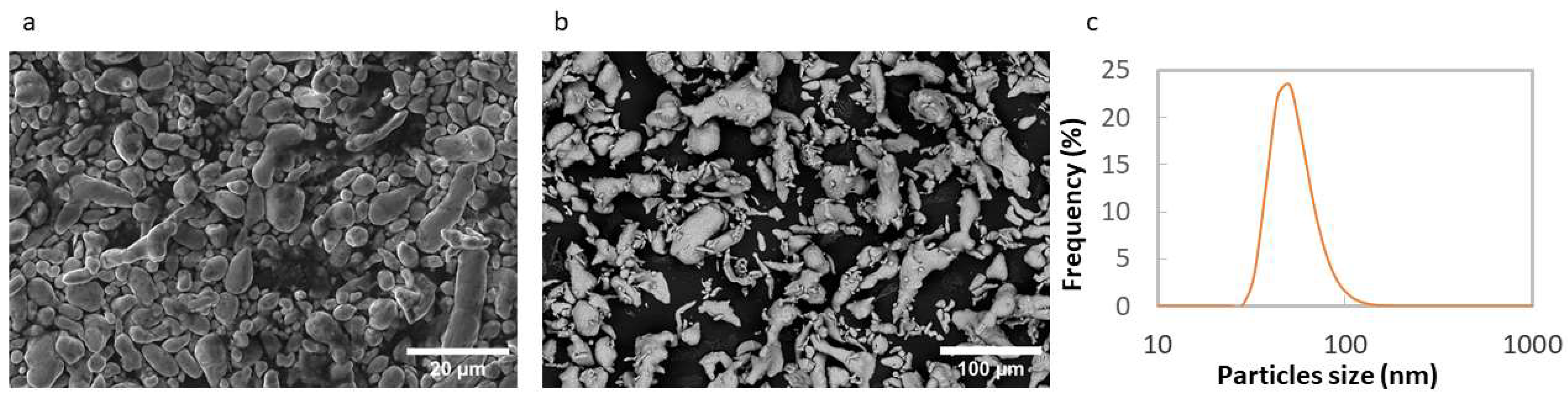
2.1. The Al Powders and Alumina Nanoparticles

Two batches of aluminum powder were used, for a reason explained further on. The first one (denoted by Al-99.5) produced by gas atomization had a purity of 99.5%. The specifications provided by Thermo Fischer Scientific indicate maximum Si and iron contents of 2500 ppm and 3500 ppm, respectively. The particle size measured by analysis of SEM images ranged from 2 to 81 µm, with an average value of 8 µm. The more or less ellipsoidal-shaped powder particles (see Figure 1a) were constituted with approximately 500 nm-large Al grains, according to X-ray diffraction measurements (using procedures detailed below).
The second batch (denoted by Al-99.9), provided by GoodFellow (Goodfellow Cambridge Ltd., Huntingdon, UK), had a nominal purity of 99.9%. The specifications indicate maximum Si and iron contents of 400 ppm and 300 ppm, respectively. The particle size ranged from 4 to 101 µm, with an average value of 17 µm. This powder, produced by air atomization, exhibited more heterogeneity in the shape of its particles (see Figure 1b), made of 2.5 to 5 µm-large Al grains, according to SEM observations of powder grains cross sections (obtained by embedding the powder in resin and polishing it), on which the grain boundaries, decorated by iron-rich intermetallic particles, were readily visible. A colloidal suspension of γ-Al2O3 nanoparticles in isopropanol from Sigma-Aldrich (Sigma-Aldrich, St. Louis, MO, USA) provided the reinforcement, with a weight fraction between 2 and 6%. The effective diameter of the particles measured by dynamic light scattering using a Zetasizer nano-ZS Zen 3600 from Malvern (Malvern Panalytical, Malvern, UK) at 25 °C with a scattering angle of 173° ranging from 30 to 120 nm, with an average of 50 nm, as shown in Figure 1c. The suspension was sonicated during 1 h before use, hoping to reduce particle clustering.
The synthesis of Al—Al2O3 nanocomposites included two or three steps, depending on the consolidation process, namely: (1) powder mixing and ball milling (common to both processes), (2) powder encapsulation (for ECAP only), and (3) consolidation by ECAP or SPS.
All powder manipulations were performed in a glovebox, under a controlled argon atmosphere (H2O and O2 levels below 0.5 ppm). However, according to the literature [35], due to previous handling and storage by the providers, the presence of a few nanometer-thick amorphous and partially hydrated oxide layers on the Al powder particles cannot be avoided.

2.2. Powder Mixing and Ball-Milling

Ball-milling serves several purposes: (1) to fracture and disperse the native oxide on the powder particles, promoting direct metal-on-metal contact and bonding during ECAP or SPS, (2) to obtain a uniform dispersion of the added γ-Al2O3 nanoparticles, both inside the grains and along the GBs, and (3) to reduce the Al grain size in order to obtain harder nanocomposites, and efficient Zener pinning of the GBs by nanoparticles of radius r, and volume fraction fv, which requires that the grain size (assuming an equiaxed shape) is less than [5]:
d m a x = 4 r 3 f v ,
Considering the mean initial radius of the present nanoparticles, r = 25 nm, and the volume fractions corresponding to weight fractions of 2%, 4%, 5% or 6%, Equation (1) yields dmax = 1.24 µm, 0.62 µm, 0.495 µm, and 0.415 µm, respectively. However, these values constitute overestimates, since, as shown below, milling tends to significantly reduce the size of the nanoparticles.
The mixed Al powder and Al2O3 suspension were first heated at 50 °C for 1 h inside the glovebox in order to evaporate the isopropanol. The blend was then poured into a hard steel grinding jar with 10 mm hard steel balls with a ball-to-powder ratio of 10:1. A small amount (2.5 wt.%) of ethanol was added as process-control agent. After sealing the jar in the dry argon atmosphere of the glovebox, milling was performed in a Retsch PM100 planetary ball mill (Retsch GmbH, Haan, Germany), by sequences of 30 min interrupted by 10 min pauses to limit the temperature rise. The total milling time, excluding the duration of the pauses, varied between 4 h and 16 h and the rotation speed between 100 and 400 rpm. The rotation direction was inverted after each pause. After milling, the blended powders (back in the glovebox) were heated again at 50 °C for 1 h to evaporate any residual ethanol. Vickers hardness measurements were made on the milled powders under a load of 10 g, maintained during 12 s (and averaged over 10 measurements) after embedding the powder in resin and lightly polishing the surface.

2.3. Powder Encapsulation for ECAP

Two types of blind tubes were used to encapsulate the powders. Externally square-shaped copper tubes, 19.8 mm × 19.8 mm × 95 mm, with a Φ16 mm cylindrical blind hole, were used for ECAP-BP-RT. Copper was chosen because of its adequate strength and ductility at room temperature, but brass was preferred for ECAP-HT (around 385 °C, as explained below) because it exhibits a much higher strength than copper at 350–400 °C, while showing a sufficient ductility to avoid failure during ECAP. For ECAP-HT, 115 mm long cylindrical brass tubes, with 19.9 mm and 15.9 mm external/ internal diameters, were thus used. The tubes were filled with milled powder blends inside the glove box, with repeated manual tapings in order to increase the relative density of the powders (typically in the range of 45–55%). The tubes were then sealed with a 5 mm long copper or brass plug, which was press-fitted with a manual press. The slight argon overpressure induced inside the tube by the press-fitting of the plug was hoped to hinder the entrance of moisture and oxygen.

2.4. Consolidation by ECAP

ECAP was realized either at RT (at LEM3, Metz) or at a temperature around 385 °C (at LMS, Palaiseau). In the first case, the ECAP channel had a 20 mm × 20 mm square section, a channel intersection angle of 90°, and an inner radius of 2 mm. A back pressure ranging from 88 to 311 MPa was applied, depending on the sample, by the plunger of a hydraulic actuator within the die exit channel. The tubes were greased with Mo2S, and extruded at a speed of 0.3 mm/s. At HT, the ECAP channel had a 20 mm cylindrical section, and inner and outer angles of 90°. Heating was performed by three 1500 W resistance heaters fixed on three external surfaces of the die. In order to induce some back pressure and make the sample re-introduction easier, the exit channel had a slightly reduced diameter (19.5 mm). The tubes were lubricated by a mineral oil suitable for high temperatures and were also extruded at speed of 0.3 mm/s. The Bc route was followed when more than one pass was done, on both types of ECAP processes. After ECAP, the copper or brass envelopes were removed by machining. Cylindrical samples of nanocomposites, approximately ϕ = 15 mm in diameter and 60 mm in length, were obtained after ECAP-HT, while the parallelepipedal samples issued from ECAP-BP-RT were approximately 55 mm × 12 mm × 12 mm. Longitudinal sections (cut in the XY plane of the last ECAP pass, where X and Y denote the exit and entrance directions, respectively) were prepared, for observations and micro-hardness measurements.

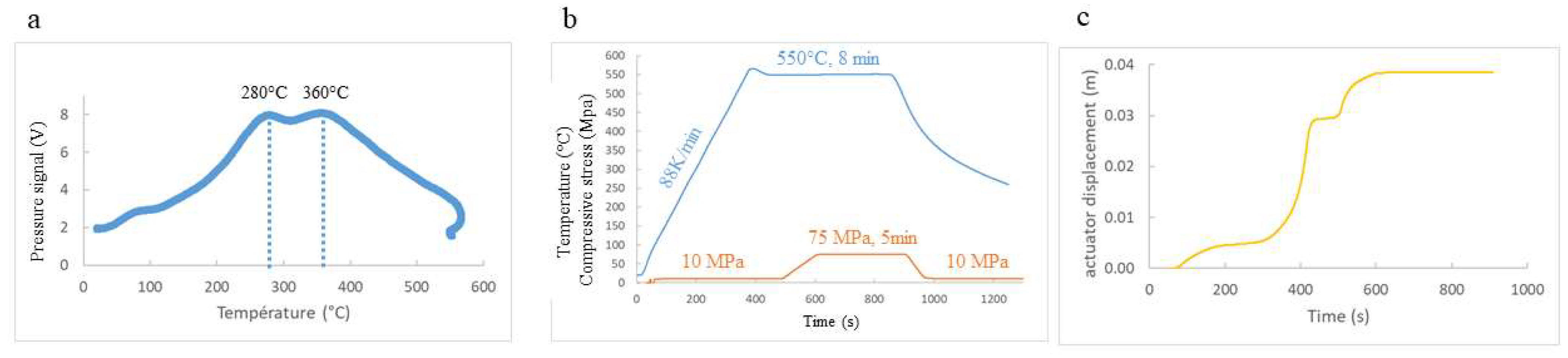
2.5. Consolidation by SPS (at ICMPE, in Thiais)

The milled powder mixtures were poured into a graphite mold, 15 or 20 mm in diameter and lined with grease proof graphite paper. A DR. Sinter Lab 515S SPS machine (Fuji Electronic Industrial, Saitama, Japan) was used, with 12 current pulses followed by two 3.3 ms long off times. The SPS chamber was first evacuated, then flushed with argon, and then evacuated again down to a residual pressure around 6 Pa. Then, a pulsed electric current, flowing through the graphite mold and the powder, allowed heating at a rate between 88 and 104 K/min, under a low axial compression (10–15 MPa), in order not to hinder powder degassing. Although the vacuum pump tends to moderate the transient pressure build-up inside the chamber due to the gas released by the powder, it does not completely prevent it, and the monitoring of the pressure evolution during the heating ramp (Figure 2a) provides useful qualitative indications on the progression of degassing. In this example, the pressure starts to rise as soon as the temperature increases, exhibiting two peaks at 280 and 360 °C, and then drops to recover its initial value near 550 °C. Powder degassing for these composition and milling conditions was thus assumed to be finished at this temperature, which was then held constant for 2 to 8 min (Figure 2), while the axial stress was ramped within one or two minutes to 75, 100, or 125 MPa, and held constant during the remaining duration of the temperature plateau. The power was then ramped down within 10 s to 1 min, under an axial compression progressively reduced to 10–15 MPa. Cylindrical samples of nanocomposites, ϕ = 15 mm or ϕ = 20 mm in diameter and 12 to 13 mm in height, were obtained after SPS consolidation. Longitudinal sections (r-Z plane, where r and Z denote the radial and axial directions, respectively) were prepared from the consolidated cylinders, for observations and micro-hardness measurements.

2.6. Microstructural Characterization Techniques

The densities of the consolidated samples were measured by Archimedes’ method at 20 °C in distilled water, and will be provided in percentage of the full density, estimated from those of Al and Al2O3, using a rule of mixtures. The density measurements were made on the entire consolidated specimens (for ECAPed samples, after removal of the copper or brass tube) before machining various samples for microstructural observations, annealing tests, compressive tests, or sliding wear tests. The measured values thus represent an average. Tomographic observations would be necessary for a full 3D characterization of potential density gradients in the samples.
After mechanical and electrolytic or ionic polishing, the longitudinal sections were observed with a Keyence digital optical microscope (Keyence, Osaka, Japan) and/or a ThermoFischer Scientific Quanta 650 FEG environmental scanning electron microscope (ThermoFischer, Waltham, MA, USA). Statistical data on the size of the iron-rich intermetallic particles, looking white on the SEM images captured from the back-scattered electron signal, was obtained by image analysis techniques. Electron back-scattered diffraction (EBSD) mappings of grains orientations were obtained using the AZtecHKL software from Oxford Instruments (Abingdon, UK) with a step size of 50 nm. A misorientation of more than 10° was used to detect the grain boundaries, and grains with an internal average misorientation smaller than 2° were considered as recrystallized. In a few samples, texture analysis was performed by X-ray diffraction (XRD), on a Bruker D5000 apparatus, using a Cobalt Kα source (λ = 1.793 Angstrom) at 40 kV and 30 mA, for a diffraction angle, 2θ, ranging from 0 to 75°, with a step size of 2.5° and an azimuthal step of 5°. The pole’s figures were plotted using the ATEX software [36] based on the (111), (200), (220), and (311) planes’ diffraction peaks. X-ray diffraction profiles were also obtained in order to determine crystallite size. Diffraction patterns were acquired with an angle, 2θ, ranging from 30 to 85°, with a step size of 0.03°, and 1 s data collection per step, using a Bruker Discover D8 apparatus equipped with a LynxEye XE-T linear detector (LynxEye AB, Stockholm, Sweden), a Soller split opening of 2.5°, a fixed slot opening of 0.5°, and an open receiving slot of 9 mm. Data post-treatment was performed using the Rietveld analysis program Maud (version 3.0, Luca Lutterotti, University of Trento, Italy, https://software.pan-data.eu/software/76/maud, accessed on 1 December 2021) [37]. The Delft model [38,39], which considers spherical grains, was used to analyze the line broadening, taking the instrumental broadening into account, and to deduce the mean grain size, which was feasible only up to 295 nm. The collected data were used to detemine the mean grain size (from EBSD when it was above 0.3 µm, from X-ray diffraction, below). For the finest microstructures, thin foils were machined, using a focused ion beam (FIB), and TEM observations were made at ICMPE on a Tecnai F20 apparatus along with EDS local chemical analyses (EDAX system, with a SDD Octane Optima 60 detector and the TEAM software), as well as crystal orientation and crystalline phase mappings using the PACOM technique [40].

2.7. Mechanical Characterization Techniques

Ten Vickers microhardness measurements were performed on each specimen (under 2N applied during 12 s) and averaged.
Cylindrical specimens, 4 mm in diameter, and 7 to 8 mm in height, were extracted from the macroscopically sound nanocomposite samples, for compression tests, normal to the die exit channel for those issued from ECAP-BP-RT, and parallel to the compression-axis for those issued from SPS. For comparison, additional compression samples were cut parallel to the axis of the square-shaped Al 1050 bar, whose microstructure is shown on Figure 1. The two ends of the samples were lubricated, and an alignment ball joint was used. The displacement rate in compression was chosen to yield an approximate strain rate of 2.10−3s−1. The axial strain was measured continuously by optical tracking of two black paint dots on a white background approximately 6 mm apart.
Pin-on-disc sliding wear tests were run, using cylindrical nanocomposite specimens 4 mm in diameter and 7 mm in height pressed against a rotating 40 CMD8 steel disc (HV > 340), with a normal pressure of 0.8 MPa applied by a 10 N hanged mass. The sliding rate was 0.5 m/s and the sliding radius 40 mm. The friction coefficient was deduced from the measured torque. The tests were stopped after 1000, 2000, and 3000 m cumulated sliding distances, and after accurate measurements of their mass, the samples were mounted again, with the wear tracks in the same position as during the previous run. The wear rate was obtained as the slope of the cumulated mass loss versus cumulated sliding distance curve.

2.8. Characterization of the Thermal Stability

A 1 h, annealing at 400 °C under an argon flux was applied to a few specimens with a heating rate of 6.3 °C/min. It was followed by natural cooling in the furnace. Finally, optical or SEM observations as well as Vickers hardness measurements were performed again, in order to assess the effects of the thermal treatment on the microstructure, cracking, and hardness.
A heating stage mounted in the Quanta 650 Environmental Scanning Electron Microscope was also used to perform in situ annealing on small cylinders (3–4 mm in diameter and 3 to 5 mm in height), cut from the hardest ECAPed samples, to monitor the appearance of cracks on the polished surface, corresponding to a longitudinal section.

2.9. Comparison with Bulk Al 1050 Alloy

Bulk Al 1050, which has nearly the same impurity content as the Al powders, was used for comparisons. The mean grain size was 20.4 µm and the hardness HV = 25, in the as-received 20 mm × 20 mm square-shaped bar, delivered in a strain-hardened, «H12», condition.

3. Results and Discussion

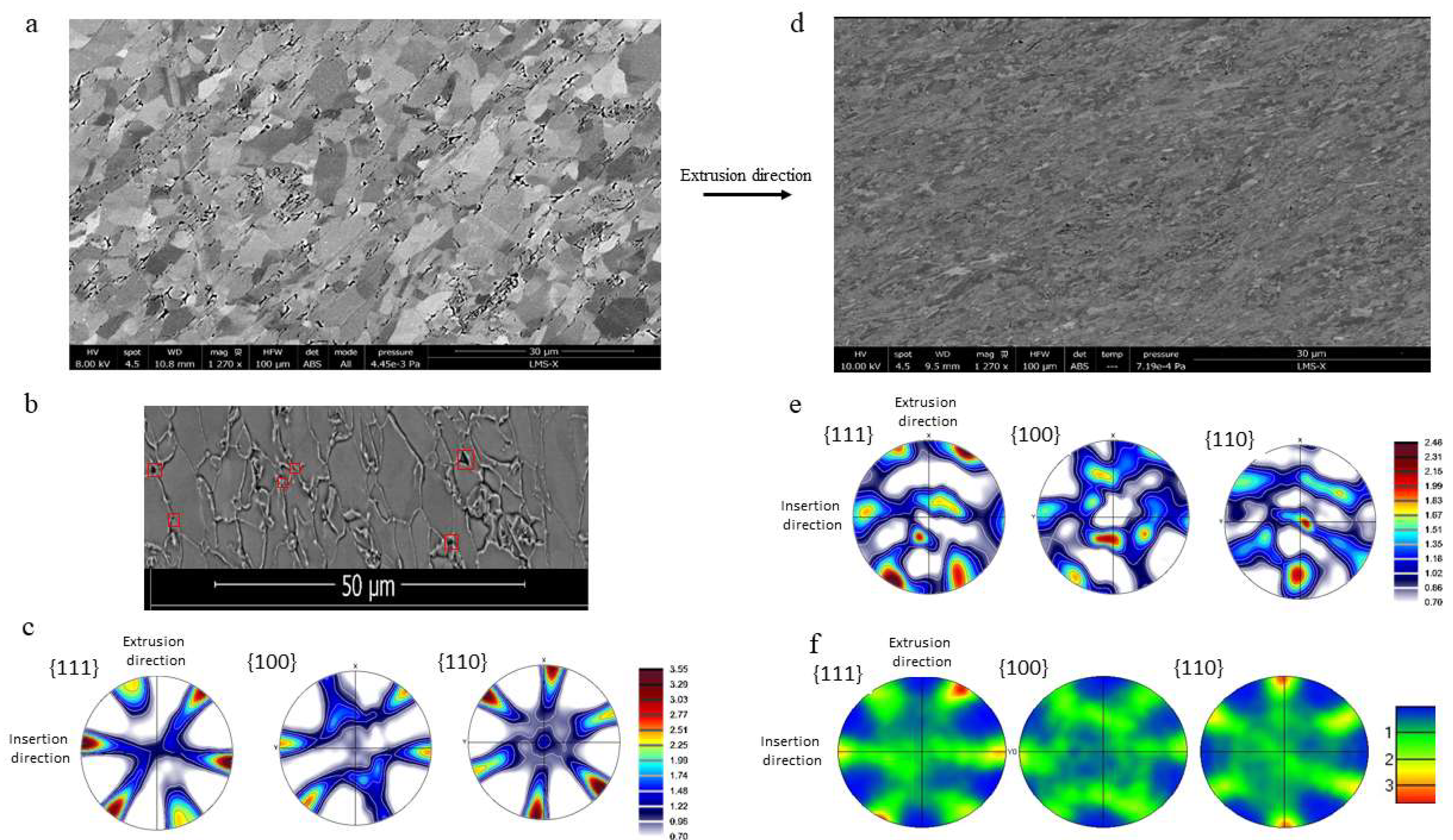
3.1. Compared Microstructures of the Nanocomposites, Depending on Their Consolidation Process

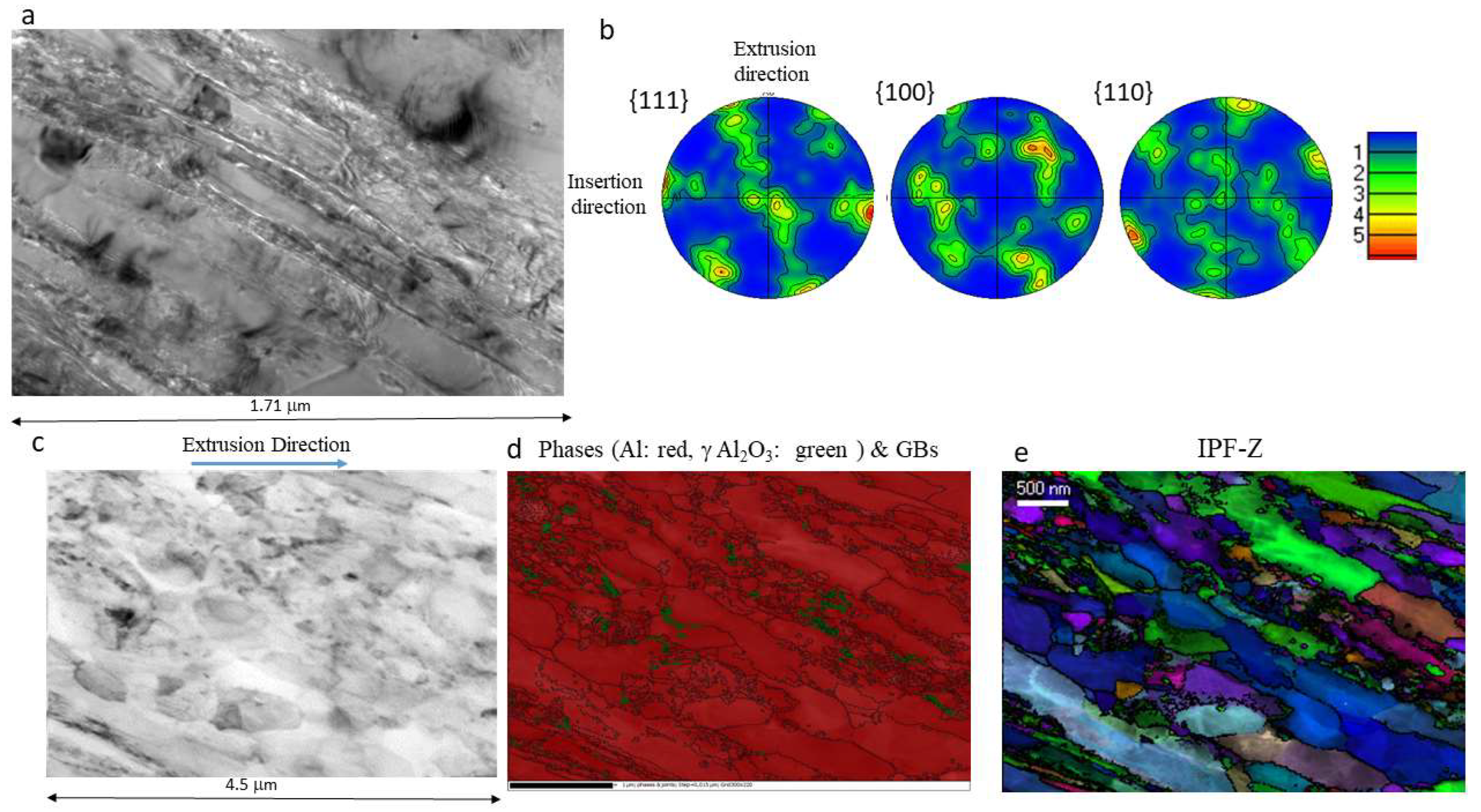
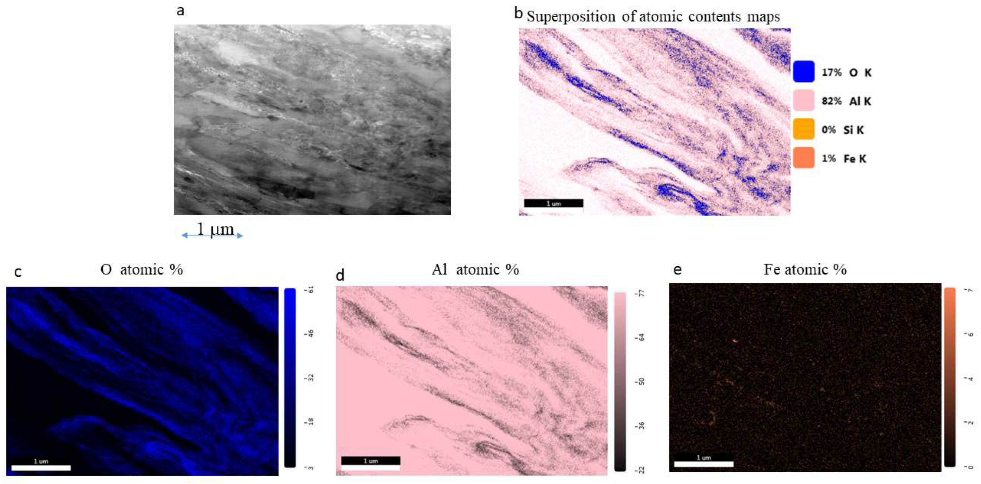
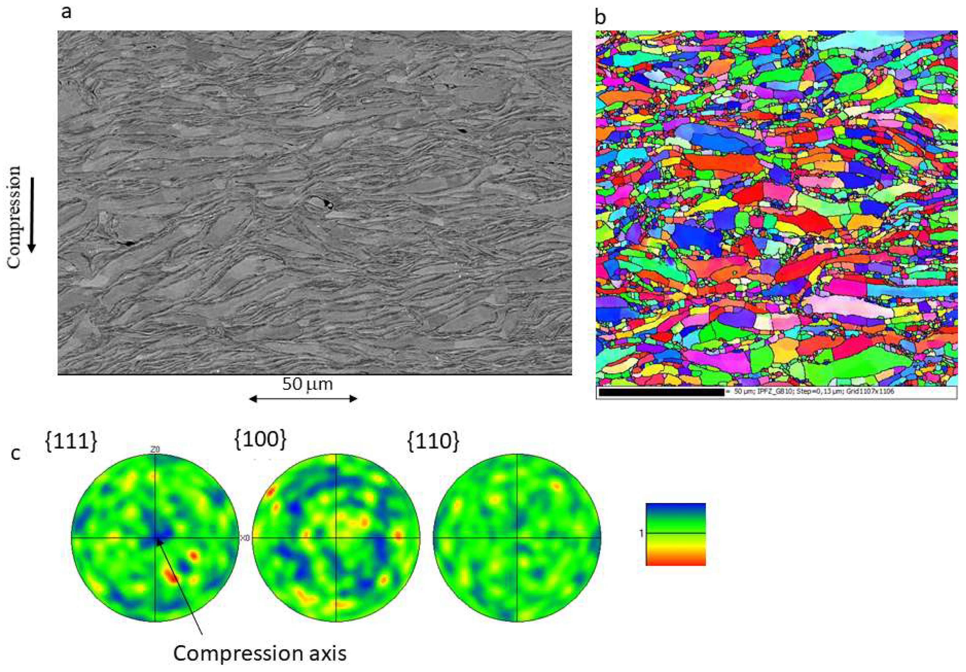
3.1.1. Specimens Consolidated by ECAP

About 20 samples were synthetized by ECAP-HT, and 15 by ECAP-BP-RT, with various nanoparticles contents (0 to 6 weight%), milling times (from 4 to 16 h), rotation speeds (from 160 to 225 rpm), and number of ECAP passes (1 to 6) so as to find an optimal combination of parameters in terms of mechanical properties. Rather than presenting results for 35 specimens, some examples and comparisons, chosen for the useful conclusions that they allow to draw, are highlighted below. Table 1 compares the process parameters and basic results for two pairs of specimens, with similar powder composition and milling conditions, produced with the same number of passes, either by ECAP-BP-RT or ECAP-HT.
At 385 °C, in one pass without back pressure, unmilled 99.5% pure aluminum powder was densified to 98.5% of its full density, with a peak pressing load around 50 kN. No damage was visible at the macroscale, but a lot of micropores, elongated in the shearing direction (Figure 3a), mostly located along the grain boundaries (GBs), sometimes forming intergranular microcracks by their coalescence, were observed with the SEM on a longitudinal section. Triangular-shaped cavities, typical of grain-boundary sliding, were observed at triple junctions (red squares on Figure 3b). The mean grain size and shape factor were 2.5 µm and 2, respectively. 38% of these grains were recrystallized. X-ray diffraction measurements (Figure 3c) revealed a mild texture (maximum texture index around 3.5), typical of aluminum simply sheared by ECAP [41].
The same unalloyed and unmilled Al-99.5% powder was consolidated to 98.5% also, in one pass by ECAP-BP-RT, with BP = 88 MPa, but this required a seven times higher peak-pressing load (350 kN). Again, no damage was observed at the macroscale, but SEM observations of a longitudinal section (Figure 3d) revealed microcavities. The latter were however much smaller than in the previous sample, although still located along GBs, and at their triple junctions. Although still visible, these signs of GB sliding were much less profuse. The hardness of the extruded sample was substantially higher than after ECAP-HT (HV = 64.6 ± 1.1, instead of 41.7 ± 0.6), in accordance with a smaller mean grain size (1.16 µm). The mean grain aspect ratio (2.0) was not different from that of the previous sample. Only 18% of these grains were recrystallized (as compared to 38% in the previous sample). The texture measured by XRD (Figure 3e) was less characteristic of shear deformation than in previous specimen, which was unexpected, considering the less profuse signs of GB sliding during ECAP-BP-RT. Furthermore, Arzaghi et al. [41] have shown that the ECAP-induced texture of aluminum is not different, with or without the activation of non-octaedral slip systems, which occurs at high temperature. Therefore, the difference observed here was attributed to some heterogeneity of plastic flow between the front, mid-length, and back areas of the sample, suggested by gradients in the grain elongation directions, which was around 45° only in the central part. The pole figures, obtained by EBSD (Figure 3f) in this area (where the grain size, elongation and recrystallization data mentioned above were collected) are actually typical of shear deformation [41]. No such heterogeneity was observed in samples subsequently extruded with a higher back pressure (180 to 310 MPa, instead of 88 MPa here).
The smaller grain size and recrystallized fraction after ECAP-BP-RT, and the more discrete signs of GB sliding and migration than after ECAP-HT, are consistent with less active dynamic recovery, grain growth, diffusion-assisted phenomena, and lower GB mobility at lower ECAP temperature. However, it must be kept in mind that, in spite of the denomination «ECAP-BP-RT», severe plastic deformation naturally induces thermal dissipation, and thus a non-negligible temperature rise. Based on numerical simulations of ECAP consolidation of precompacted 2124 Al alloy powder at room temperature, Elkhodary et al. [22] estimated that even at a moderate pressing rate, the temperature can rise locally up to 216 °C. Since the load (and thus the stresses) are nearly ten times higher during ECAP-BP-RT than during ECAP-HT, while the shear strains, controlled by the die geometry, are similar, the plastic deformation energy (partly dissipated as heat_ is thus much higher in the first case. The temperature differential between ECAP-BP-RT and ECAP-HT is thus probably less than the 360 °C nominal temperature difference.
A second comparison can be made for Al-99.5% powder blended with 2 wt.% alumina nanoparticles milled during 4 h at 225 rpm. After two passes of ECAP-HT at 385 °C, with a peak pressing load around 60 kN, a hardness of 92 ± 3.7 was obtained, but the sample exhibited so many cracks along the ECAP shearing planes (Figure 4a) that its density (which would have been meaningless) was not measured. Note the significant opening of these cracks, which would not be observed after purely shear-driven fracture, and whose origin will be discussed later. Such macroscale multiple cracking along the ECAP shearing planes, with a significant opening of the cracks, occurred systematically when the nanocomposite hardness was above 55. Hardnesses as high as 153 were obtained by ECAP-HT of the most severely milled powders, but at the expense of the sample integrity. The higher the hardness, the higher the density and length of the cracks. Such a problem, previously reported in the literature, was attributed to shear strain localization [17], a lack of ductility of hard, nanocrystalline, or severely milled powder [42], the inability of hard powder particles to increase their mutual contact surface by shear flow, and their tendency to roll on each other [18]. An additional explanation will be suggested further on.
By contrast, for the same powder mixture (Al-99.5% with 2 wt.% alumina) and milling conditions (4 h at 225 rpm), a macroscopically damage-free sample (Figure 4b) was obtained after two passes of ECAP-BP-RT with BP = 250 MPa (100 kN), but this required a nearly ten-times higher pressing load (562 KN). The hardness was not higher (HV = 91 ± 3.2) than for ECAP-HT, and the density was only 94.2% of the ideal value. The chip-like shape of milled powder particles, more or less folded and entangled, was still visible on the SEM images, where sub-micron intermetallic particles can also be seen. Long, but hardly open microcracks were present along their interfaces, often aligned in the shearing directions. The mean grain size (measured by X ray diffraction_ was 218 nm. While for the first pair of specimens issued from unmilled powder, the mean grain size increased and the hardness decreased significantly with the ECAP temperature, for this second pair issued from milled powder, the hardness and grain size were hardly affected by the ECAP temperature and were controlled by the milling conditions.
Figure 5 shows TEM observations of the latter sample, as well as crystalline phases and crystal orientation mappings, obtained with a step size of 15 nm, and the corresponding pole figures. It reveals that the Al grains are elongated along the ECAP shearing direction, and that their surface-weighted mean size (defined as the diameter of a circle of same area) is 175 nm, in reasonable agreement with the much more global value obtained from X ray diffraction peaks width. 46.5% of these grains are recrystallized. The pole figures reveal a significant simple shear local texture (maximum texture index around 6). The γ alumina nanoparticles that appear in green on Figure 5d have a mean size of 25 nm, twice smaller that their initial mean size before milling. They are mostly distributed along grain boundaries, where they align or form small clusters rather than inside grains. For a more objective assessment of the degree of spatial uniformity of their dispersion, the simplest quadrat-based method [43] was used. The TEM phase mapping image was subdivided in q quadrats, 5 × 5 pixels large, and the numbers xi of γ alumina nanoparticles falling in the ith quadrat were determined. Denoting by x ¯ the mean value of the distribution of xi and by s its standard deviation, a dispersion index was defined as:
D I = ( q 1 ) s 2 x ¯ ,
The higher this index, the more heterogeneous is the dispersion. The results for this sample will be reported below and compared to those of other samples, issued from 16 h-milled powder and consolidated by ECAP or SPS.
Some interfaces seem to exhibit nanocavities aligned along the ECAP shearing direction.
Mappings of Al, O, and Fe atomic contents (Figure 6) reveal oxygen segregations along some interfaces, which probably correspond to remnants of the native amorphous oxide layer initially present on the powder particles that would not have been entirely fragmented and dispersed during the 4 h long milling.
Even with BP = 250 MPa, ECAP-BP-RT failed to produce macroscopically crack-free specimens when powder milling was too severe, leading to a nanocomposite hardness above 92. This is illustrated on Figure 7a for a sample issued from Al-99.5% + 2% Al2O3 powder, milled 16 h at 225 rpm (which yields equiaxed powder particles rather than chips) consolidated in one pass of ECAP-BP-RT (HV = 149 ± 3.7, density 95.5%). It was nonetheless interesting to characterize its microstructure. On the SEM images (Figure 7b,c), the interfaces between the former powder particles are much less visible than in the previous sample, but a few microcracks along the ECAP shearing plane as well as micropores often located at triple points between former powder particles can be observed. Such damage is often associated with local recrystallization and grain growth. Intermetallic particles can hardly be observed on the SEM images. The crystalline phases (Figure 7e) and crystal orientation maps (Figure 7f) were obtained in the TEM with a step size of 8 nm. In this sample, the Al grains, elongated along the ECAP shearing direction, have a mean size of 66.7 nm, in very good agreement with the value of 65.2 nm obtained by X ray diffraction. A total of 46% of these grains are recrystallized. The intensity of the shear-type local texture (maximum index around 5.3, Figure 7g) is not very different from that of the previous sample. By contrast, the mean size of the alumina nanoparticles is only 13.7 nm, which is twice as small than in the previous sample, and nearly four times smaller than their initial size, before milling.
For the previous sample (issued from 4 h milled powder and ECAPed twice) the nanoparticles dispersion index (Equation (2)) was 7655; it was 6149 (i.e., 20% smaller) here, in spite of a single ECAP pass. There is a clear tendency of the nanoparticles to cluster and align along the ECAP shearing direction, but a longer milling time (16 h instead of 4) tends to reduce it.
Mappings of Al, O, and Fe atomic contents (Figure 8) suggest that oxygen segregations along the former powder particles (or, in other words, remnants of unbroken native oxide) are substantially reduced after 16 h milling, compared to only 4 h.
Overall, while in the conditions described above and using Al-99.5%, ECAP-HT could not produce macroscopically sound specimens with a hardness above 55, ECAP-BP-RT with BP = 250 to 315 MPa shifted this limit up to a hardness around 92, allowing the mechanical characterization presented below. However, some pores and microcracks were still present at the microscale, the hardening potential of powder milling (approximately up to 150) was not fully exploited, and TEM observations showed that native oxide fragmentation and nanoparticles dispersion (which require more severe milling) were not fully achieved.
An attempt to overcome these difficulties was made by using the second batch of Al powder (softer than the first batch due to its larger crystallite size, and expected to be more ductile thanks to its reduced impurity content) and a smaller amount of native oxide (assuming a similar oxide thickness on larger powder particles). This attempt was unsuccessful, since very little difference between ECAPed samples issued from Al-99.5 and Al-99.9 was observed, for the same nanoparticles content and milling conditions. For example, for 2% Al2O3, 16 h milling at 225 rpm, and 1 ECAP-BP-RT pass, the mean grain size and hardness were 65 nm and HV = 149 ± 3.7 for a nanocomposite issued from Al-99.5%, and was 62 nm and HV = 153 ± 1.9 for that issued from Al-99.9%. In other words, severe milling erases the initial differences between these powders, so that it is not unreasonable to compare the properties of nanocomposites issued from batch 1 and batch 2 Al powders, as long as their nanoparticles contents and milling conditions are similar. Even though the density achieved in the second sample was slightly improved (96.6% instead of 95.5%), both samples showed macrocracks. That is why SPS consolidation was investigated. In this part of the study, only the second powder batch was used.

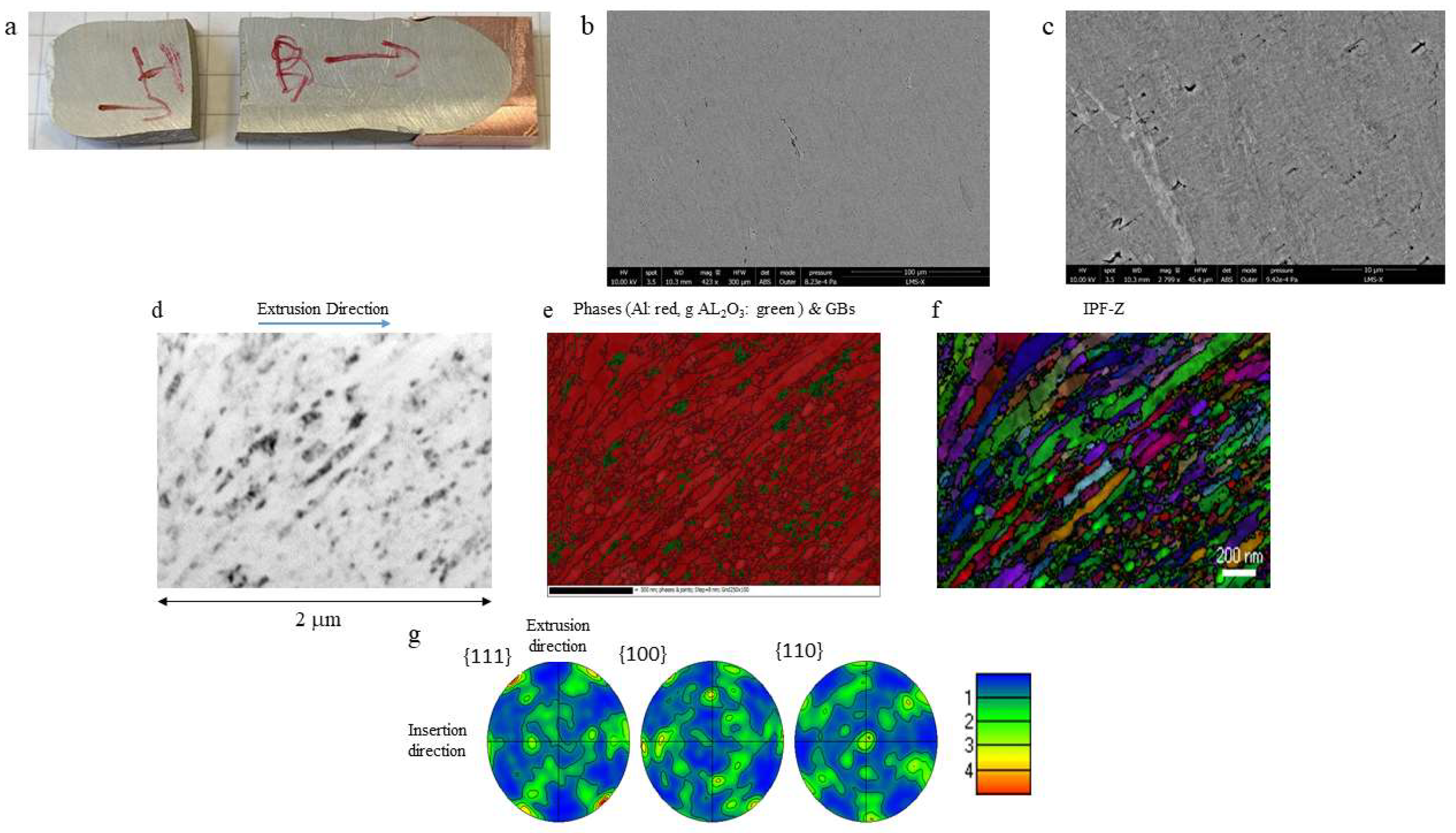
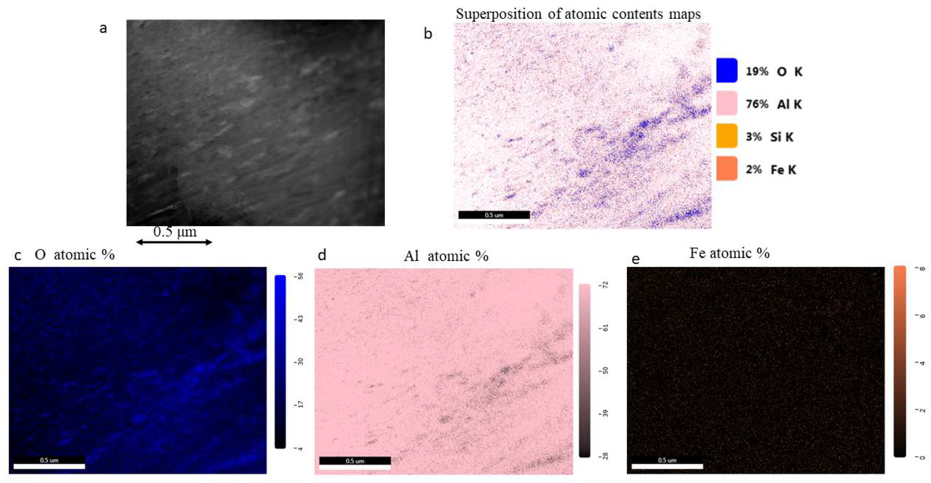
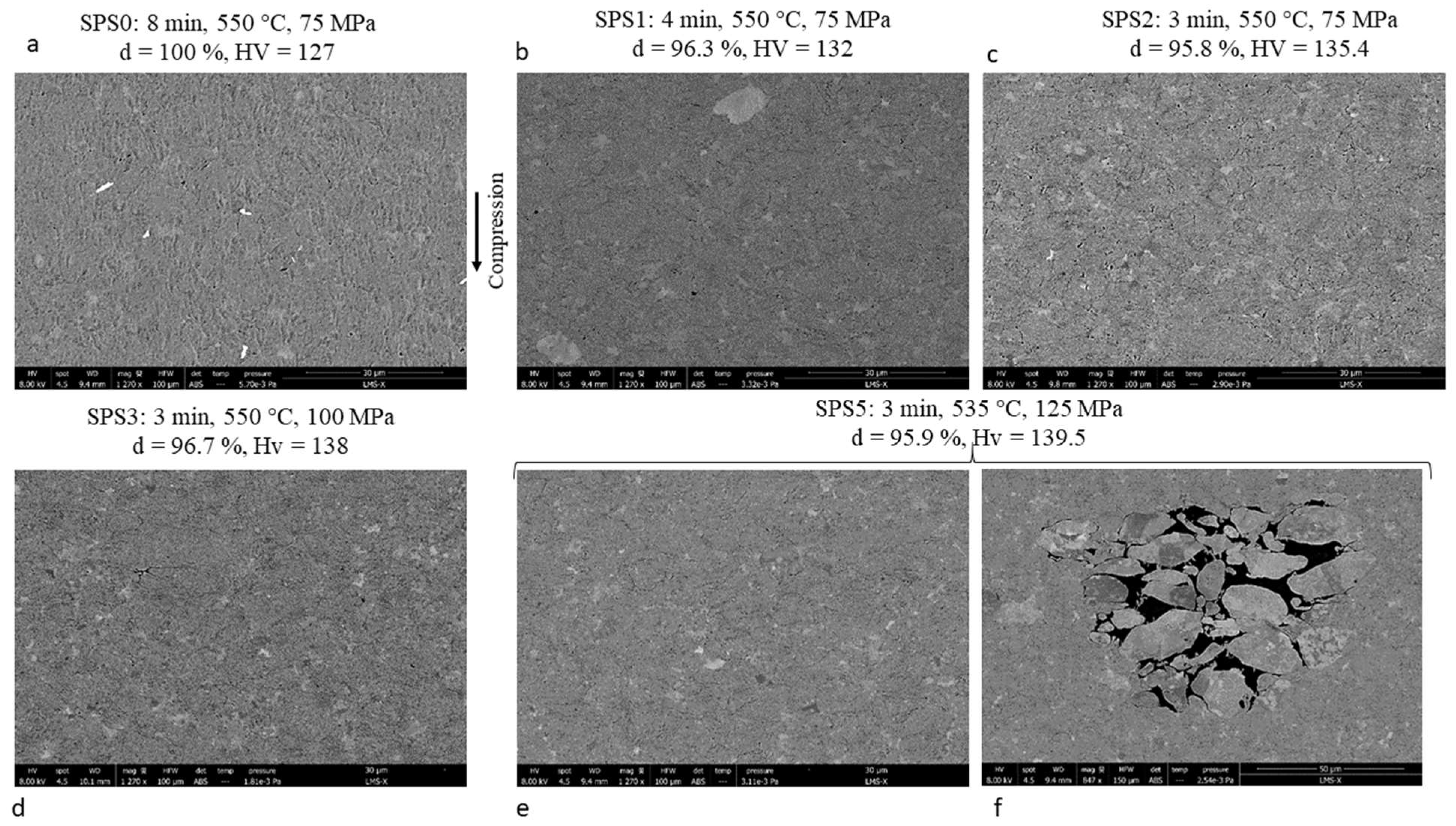
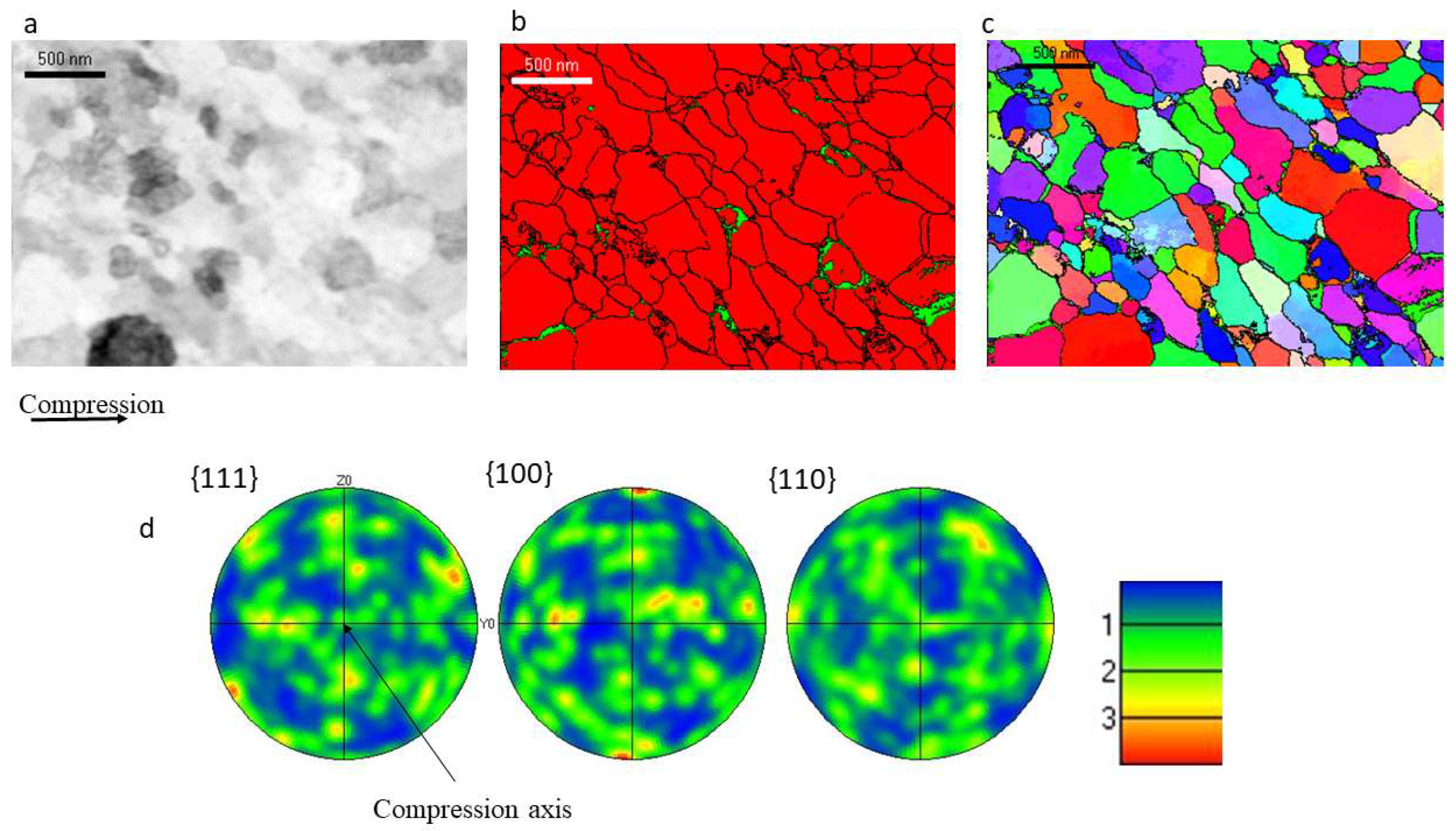
3.1.2. Specimens Consolidated by SPS

Six samples with the same composition -Al-99.9% + 2% Al2O3- were consolidated by SPS, according to the conditions reported in Table 2. While a simple temperature ramp of 6 min, up to the targeted value Tdwell = 550 °C (≈88 K/min), led to a transient over-heating up to 566 °C for the first two samples, splitting into a 5 min ramp to (Tdwell—10 °C), followed by a 1 min ramp to Tdwell, reduced the overheating to at most 4 °C. The radial and axial microhardness profiles measured on longitudinal sections after consolidation did not reveal any significant gradient in the specimens.
The disappointing hardness of the first sample, issued from Al-99.9% + 2% Al2O3 milled for 4 h at 225 rpm, HV = 54 ± 1.4, as compared to that obtained by two passes of ECAP-BP-RT or ECAP-HT on Al-99.5% + 2% Al2O3 milled in the same conditions (HV = 91 ± 3.2 and 92 ± 3.7, respectively) was due to substantial grain growth during SPS, as illustrated by the SEM observations and EBSD mappings on a longitudinal section (Figure 9).
The chip-like former powder particles are more or less aligned, normal to the compression axis, and a few defects (non-bonded powder particles) are visible here and there, in accordance with the imperfect density (96.5%). The mean grain size is 1.7 µm, as compared to 218 nm (7.8 times larger) for ECAPed samples (see Figure 5). Taking into account the milling-induced reduction in the mean nanoparticles size to 25 nm) as deduced from TEM observations on an ECAPed sample issued from the same powder, Figure 5) 2% such particles, according to Equation (1), should prevent grain growth beyond dmax = 1.23 µm provided that (1) they are uniformly distributed and (2) the grains are spherical. The fact that neither of these conditions is met after 4 h milling at 225 rpm (see Figure 5 and the dispersion index) probably explains the more substantial grain growth in this specimen during SPS. A total of 44% of these grains are recrystallized. The pole figures reveal the quasi absence of texture (max index 2.1).
The hardness of the five samples consolidated by SPS under various conditions, from powder milled 16 h at 225 rpm (Figure 10), ranged from 85% to 93.6% of that obtained after one pass of ECAP-BP-RT (HV = 149 ± 3.7) on the same powder. Some grain growth-induced softening (although less pronounced than on the same powder milled only for 4 h) thus also occurred, to various extents, during SPS. The shorter the dwell time at 550 °C (and the lower the overheating), the higher the hardness, but at the expense of the density, which decreased from 100%, for 8 min dwell-time, to 95.8%, for 2 min. The small cavities decorating the former powder particles seemed less numerous and smaller for longer dwell periods and higher compressive stresses. As expected, a reduction of the peak temperature to 535 °C also reduced grain growth-induced softening, yielding the highest hardness (HV = 139.5 ± 2.6); but again, in spite of an increase of the compressive stress to 125 MPa, this was at the expense of the sample integrity, as illustrated by the large cluster of non-bonded powder particles shown on Figure 10f. In the other samples, a few similar defects (although substantially smaller) were also observed. Contrary to the SPSed sample issued from powder milled only for 4 h, whose softer chip-like powder particles aligned more or less normally to the SPS compression axis, in the specimens shown on Figure 10, the 16 h milling time has produced hard and spheroidal powder particles, and the 75 to 125 MPa compression applied during SPS was not sufficient to induce a morphological anisotropy.
Figure 11 shows TEM observations of sample SPS0, crystal orientations, and phase mappings obtained with a step size of 8 nm, as well as pole figures. The grains are more equiaxed than in the ECAped sample issued from the same powder milled in the same conditions (Figure 7), and their mean size is larger (159 nm, instead of 66.7 nm, 2.4 times larger). A total of 72% of these grains are recrystallized (versus only 46% after ECAP-BP-RT), and little texture appears at this local scale (max index: 4). The spatial distribution of alumina nanoparticles is more heterogeneous than in the ECAped sample issued from the same powder milled in the same conditions (dispersion index 10239, as compared to 6149), probably because they were not redistributed by severe shear plastic flow, and thus remained clustered along grain boundaries without preferential orientation. However, the longer milling time at 225 rpm compared to the sample SPS4h (16h instead of 4 h) certainly improved the dispersion of the added nanoparticles in the powder, as well as the fragmentation of the native oxide layer (as deduced from TEM observations on Figure 6 and Figure 8), and led to more equiaxed grains, so that the Zener pinning of the grain boundaries was probably more efficient, and SPS-induced grain growth less pronounced (by a factor of 2.4, instead of 7.8) in spite of a longer dwell time at 550 °C (8 min instead of 5 min). The final mean grain size (159 nm) is indeed compatible with the maximum grain size predicted by Equation (1) (dmax = 679 nm), taking into account the reduced size of the nanoparticles (13.7 nm) after such milling.

3.1.3. Intermetallic Particles

Table 3 reports the mean and maximum size of the iron-rich intermetallic particles. In the as-received Al 1050 bar, a lot of heterogeneously distributed iron-rich intermetallic particles were observed, with mean and maximum sizes of 1.18 µm and 7.08 µm, respectively. According to Hannard et al. [44] “micron-sized iron-rich intermetallic particles constitute the main source of damage in aluminum alloys”. They constitute cavity nucleation sites, in ductile fracture [44], but also crack initiation sites, in fatigue [45]. Their fragmentation and more homogeneous dispersion is thus quite desirable.
By contrast, the mean and maximum sizes of the iron-rich intermetallic particles were only 0.25 µm and about 1 µm in the nanocomposites produced by ECAP from milled powder, which is an asset for the resistance to fatigue as well as for ductility. The same orders of magnitude were obtained in the nanocomposites produced by SPS, but only when overheating was avoided, and the dwell time at the peak temperature reduced to 4 min or less. When these conditions were not met, intermetallic particles as large as 2.05 µm (5 min dwell time at 550 °C + overheating) and 7.71 µm (8 min dwell time at 550 °C + overheating) were formed. On the other hand, shorter dwell periods decreased the density of these nanocomposites, due to remaining clusters of unbonded powder particles. A compromise between two opposite requirements has thus to be found.

3.2. Compared Mechanical Properties of the Materials, Depending on Their Consolidation Process

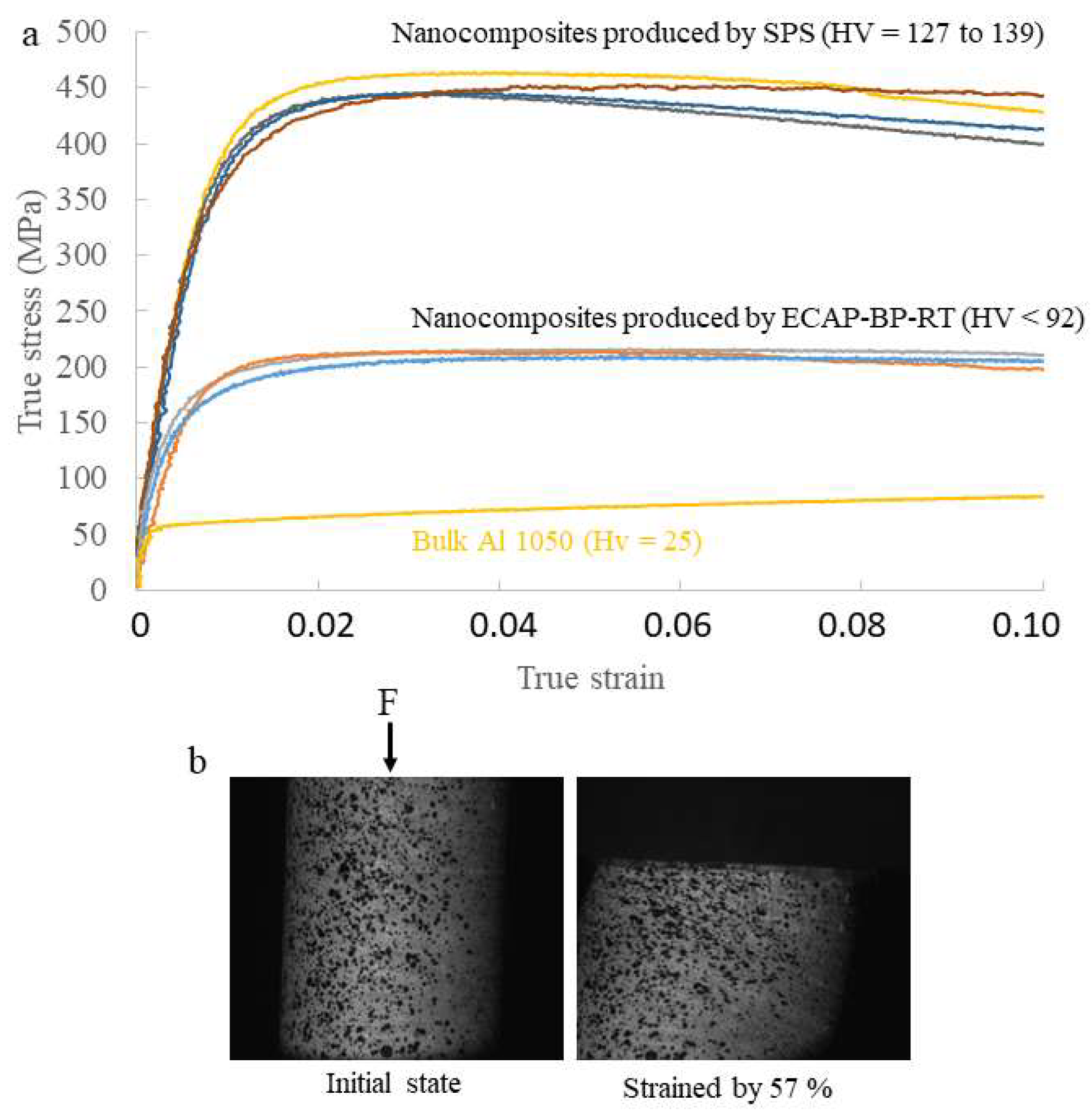
3.2.1. Compression Behavior

Figure 12a compares the true stress–true strain compression curves of various nanocomposites issued from ECAP-BP-RT (those with a sufficient integrity, and thus with HV < 92) or from SPS (HV = 126.5 to 139.5 with that of bulk Al 1050 in the as-received (grain size of 20.4 µm). The curves have been truncated at 10% strain, but most samples can sustain a much higher compressive strain, as illustrated on Figure 12b, for Al-99.9% + 4% Al2O3, milled 4 h at 160 rpm, 4 ECAP-BP-RT passes, strained by 57%, without fracture or strain localization. However, the main purpose of these compressive tests was not the determination of ductility (for which tensile tests will be performed at a later stage of the study) but just a characterization of plastic flow.
The flow stress of the nanocomposites issued from ECAP was approximately four times higher than that of bulk Al 1050 in the as-received condition. Even though the hardening stage is relatively short in these nanocomposites (ending after 2 to 4% strain), it is significant (their flow stress increases by up to 46% from their yield stress).
The flow stress of the nanocomposites issued from SPS is much higher: approximately nine times that of as-received bulk Al 1050, and comparable to that of Al 2024-T6. They also exhibit significant strain hardening (their flow stress increases by 17% to 44% above their yield stress).

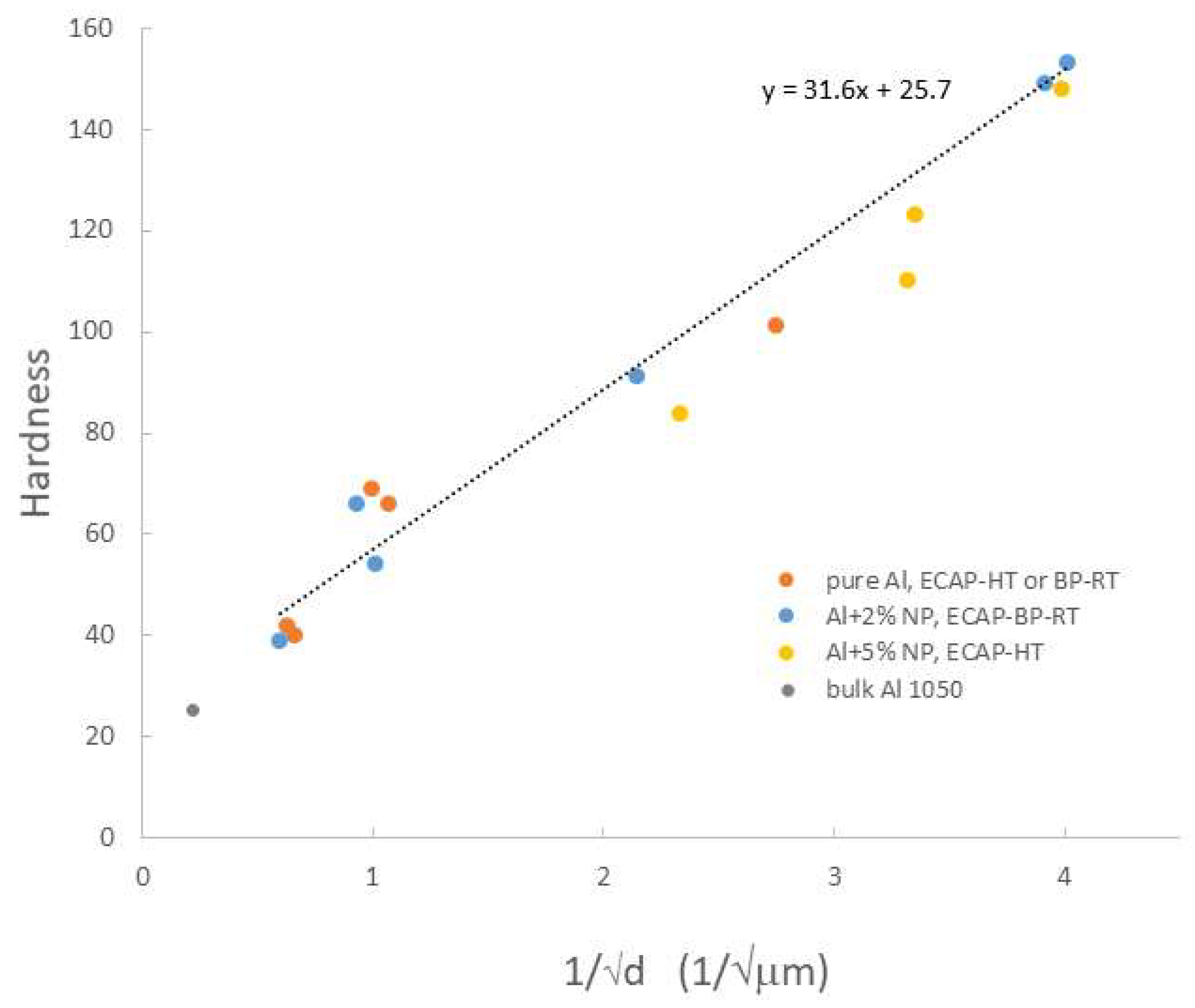
3.2.2. Microhardness

The microhardnesses of all specimens, including bulk Al1050, exhibit a Hall–Petch-like affine correlation with the inverse square root of the mean grain size (Figure 13) over wide hardness and grain size ranges (HV= 25 to 153, and 20.4 µm to 65 nm, respectively).
No direct correlation of the hardness with the nanoparticles content emerges. In fact, for a direct hardening effect, the added nanoparticles would have to get inside the grains, and hinder dislocations glide, while the TEM observations reported on Figure 5, Figure 7, and Figure 11 show that it tends to remain along the GBs even after severe milling.
However, as shown by Table 4, their presence clearly contributes to Al grain refinement, and thus indirectly to an increase in hardness when ECAP is performed at a high temperature. For an intermediate milling condition (4 h at 225 rpm), the mean grain size is divided by five by the addition of 2% nanoparticles to Al-99.5% powder. The effect is less pronounced (although still significant) for severe milling (16 h at 225 rpm): the mean grain size is twice smaller when 5% nanoparticles are added, and similar to that measured by XRD on the milled powder mixture. This implies the absence of grain growth at 380 °C within approximately 40 min under severe plastic deformation.
By contrast, for ECAP performed at room temperature (Table 5) after a mild milling (4 h at 160 rpm), the Al mean grain size does not change significantly when the weight fraction of nanoparticles is tripled.
Beyond the prevention of grain growth during ECAP-HT or SPS, the alumina nanoparticles, when properly dispersed, play an important role for the thermal stability of all ultrafine-grained nanocomposites, as shown below.

3.2.3. Sliding Wear

The results of the pin-on-disc sliding wear tests are summarized in Table 6.
Significant differences in friction coefficient were observed between the materials, and even between the nanocomposites, without any correlation with their hardness. Bulk Al 5083 (HV= 92 ± 1.2) was the most resistant to sliding wear, but two of the relatively soft nanocomposites issued from ECAP-BP-RT (HV = 64.9 and 63.8) had quasi-similar performances, nearly twice better than those of bulk Al 7075-T6. The hardest nanocomposite (HV = 126.5) issued from SPS did not perform better than the softest ones. Indeed, the resistance to sliding wear does not depend only on the hardness, but also on the ductility or toughness of sheared asperities, as shown by Brach and Molinari [46].

3.3. Compared Conditions and Hardness of the Materials, after Static Annealing, Depending on the Milling and Consolidation Process

Table 7 summarizes the outcome of static annealing tests at 400 °C, in terms of thermally induced softening (discussed in part C.3.a) and thermally induced damage (part C.3.b).

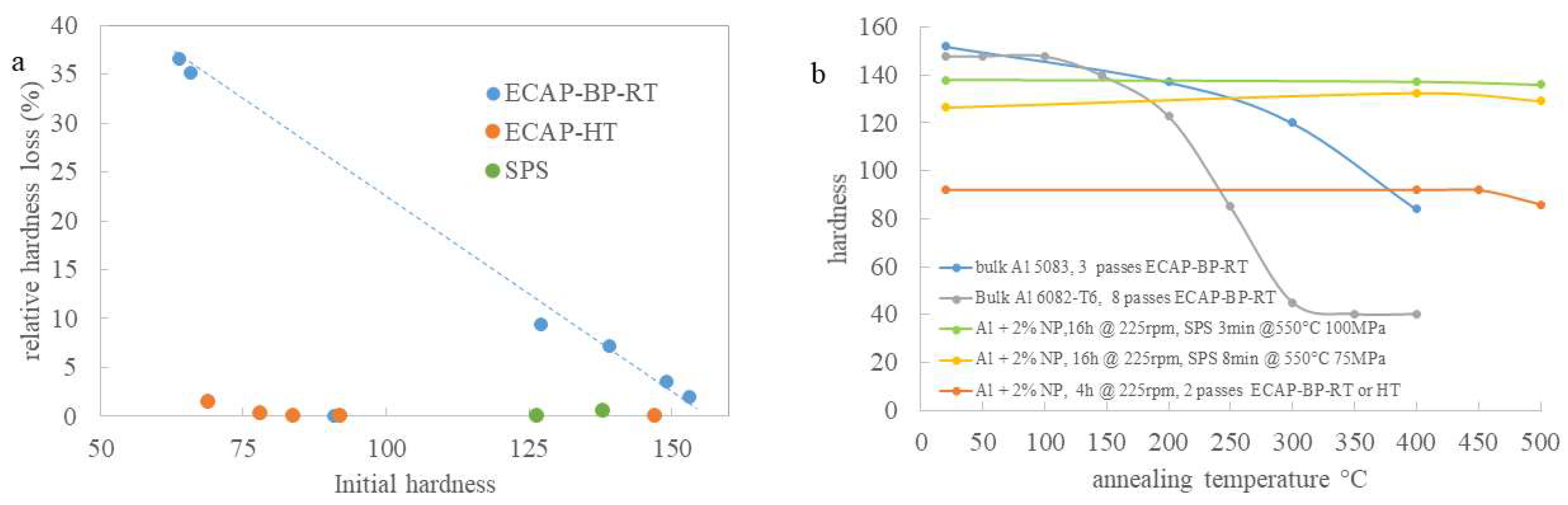
3.3.1. Thermally Induced Softening

The percentage drop in hardness due to 1 h annealing at 400 °C is plotted versus the initial hardness of the nanocomposites over the whole range of consolidated samples hardnesses (HV = 63.9 to 153) in Figure 14a.
A striking difference appears between the nanocomposites consolidated either by ECAP-HT or SPS, whose hardness was not affected by 1 h exposure at 400 °C, and those consolidated by ECAP-BP-RT. For the latter, the percentage drop in hardness reached 36.6% for the softest specimen (HV = 63.9 ± 2.2), but decreased nearly to zero as the hardness rose up to 153. The better stability at 400 °C of the nanocomposites consolidated by ECAP-HT or SPS, as compared to those consolidated by ECAP at room temperature, is probably due to their prior exposure to high temperatures during their consolidation: ≈30 min at 380 °C, for 2 of ECAP-HT passes, and 8 to 12 min between 400 and 550 °C, for SPS.
Sample #6, ECAPed at 385 °C (HV = 92 ± 3.7) did not even soften when the annealing temperature was raised to 450 °C, and at 500 °C, its hardness drop was modest (HV = 86 ± 3.3). This was even more so for sample #10 (HV = 126.5 ± 2.2) and #12 (137.9 ± 2.5) obtained by SPS at 550 °C whose hardness after annealing at 500 °C (129.2 and 135.9, respectively) was not significantly altered. Figure 14b compares the annealing-induced evolutions of the hardness for ultrafine grained (UFG) 5083 and 6082 alloys (from billets ECAPed at room temperature [1,2]) and for samples #6, #11, and #12. Although the two UFG alloys are harder at room temperature, Al 6082 quickly softens above 150 °C, and Al 5083, more gradually, above 200 °C; the hardness of the nanocomposites consolidated by ECAP-HT or SPS remains stable up to much higher temperatures.
Regarding the samples issued from ECAP-BP-RT, a more and more efficient Zener pinning due to the size reduction of the nanoparticles, the improvement of their dispersion, and that of the fragments of the native oxide layer with the severity of ball milling might explain that their drop in hardness decreases as their hardness rises.

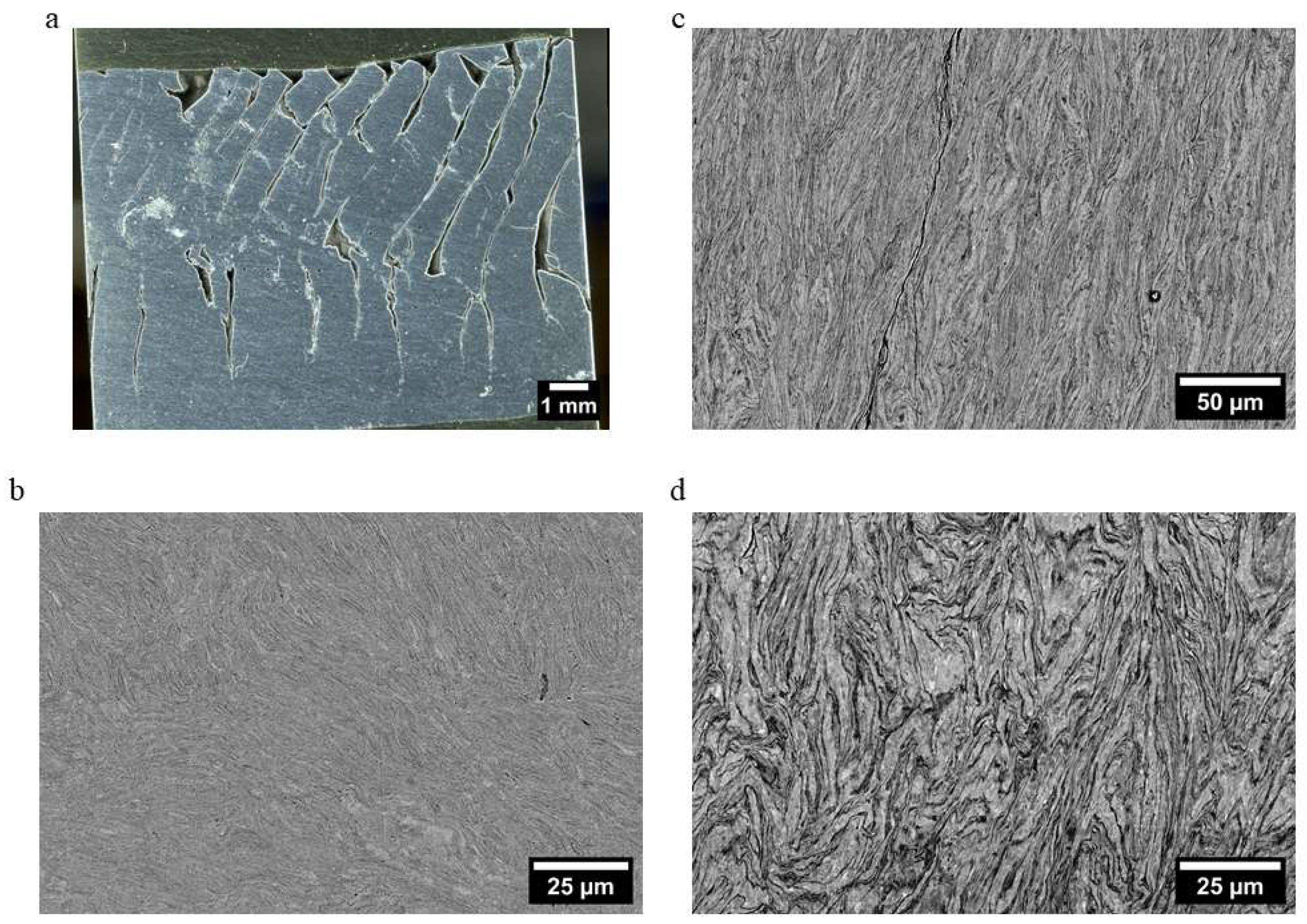
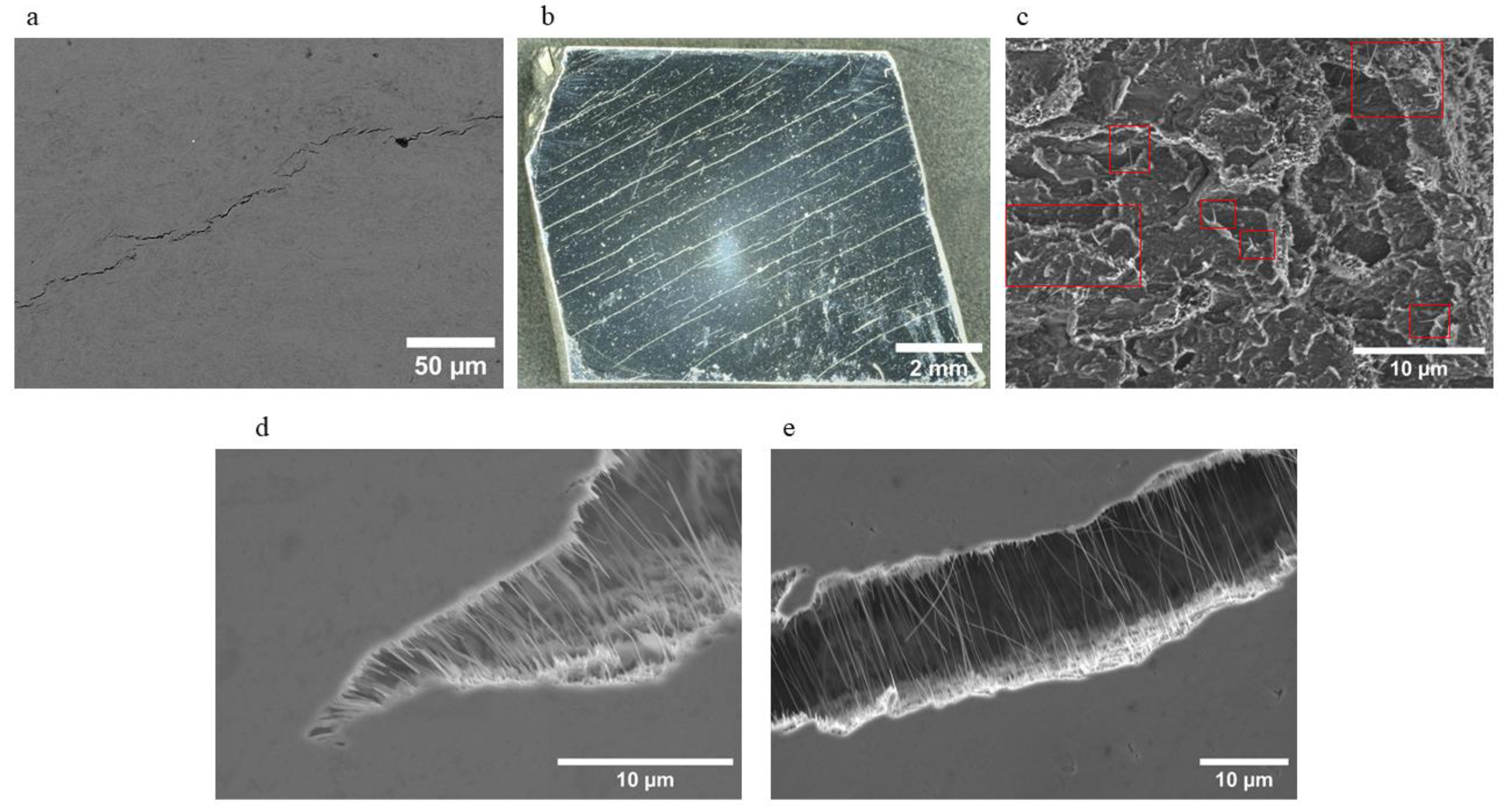
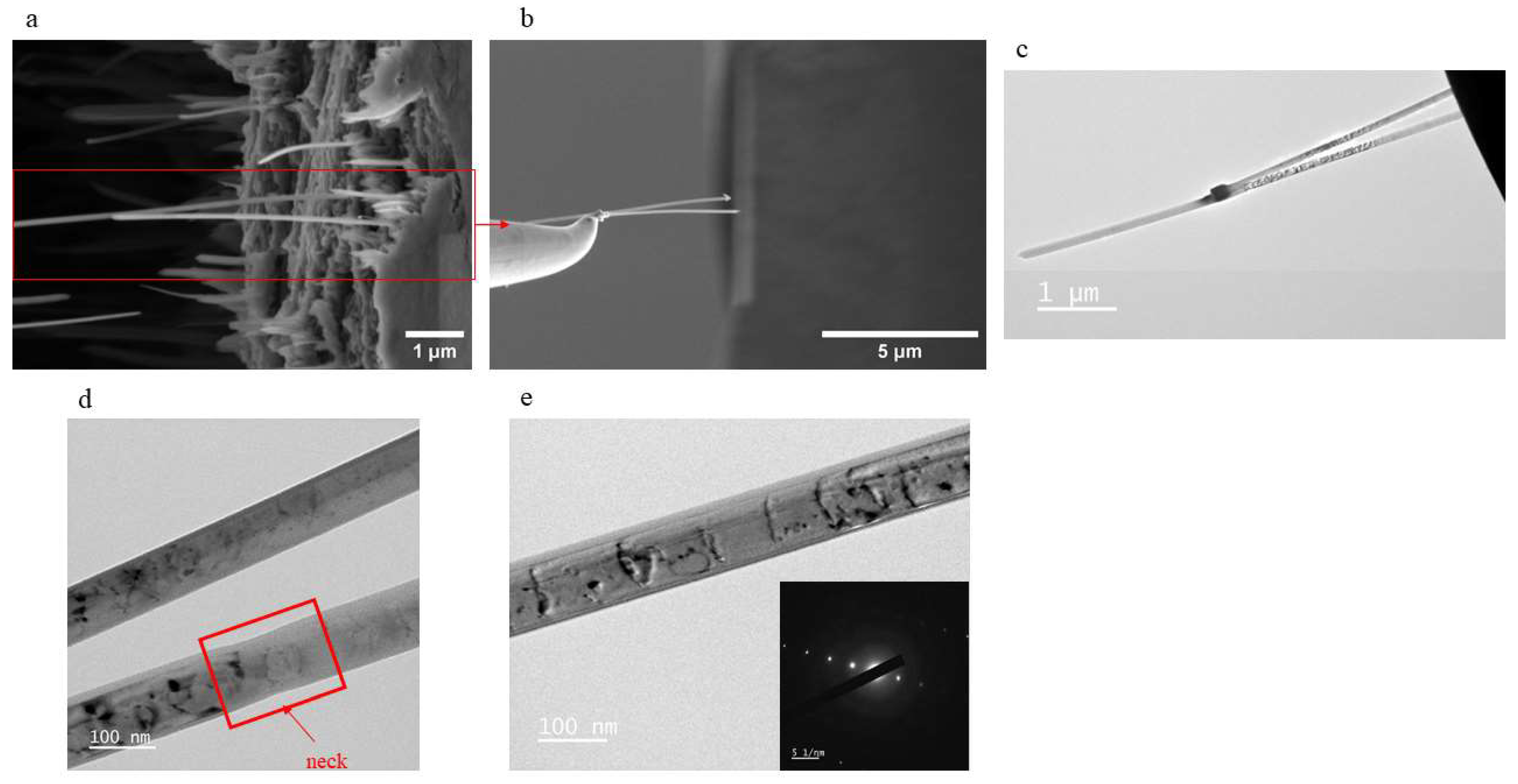
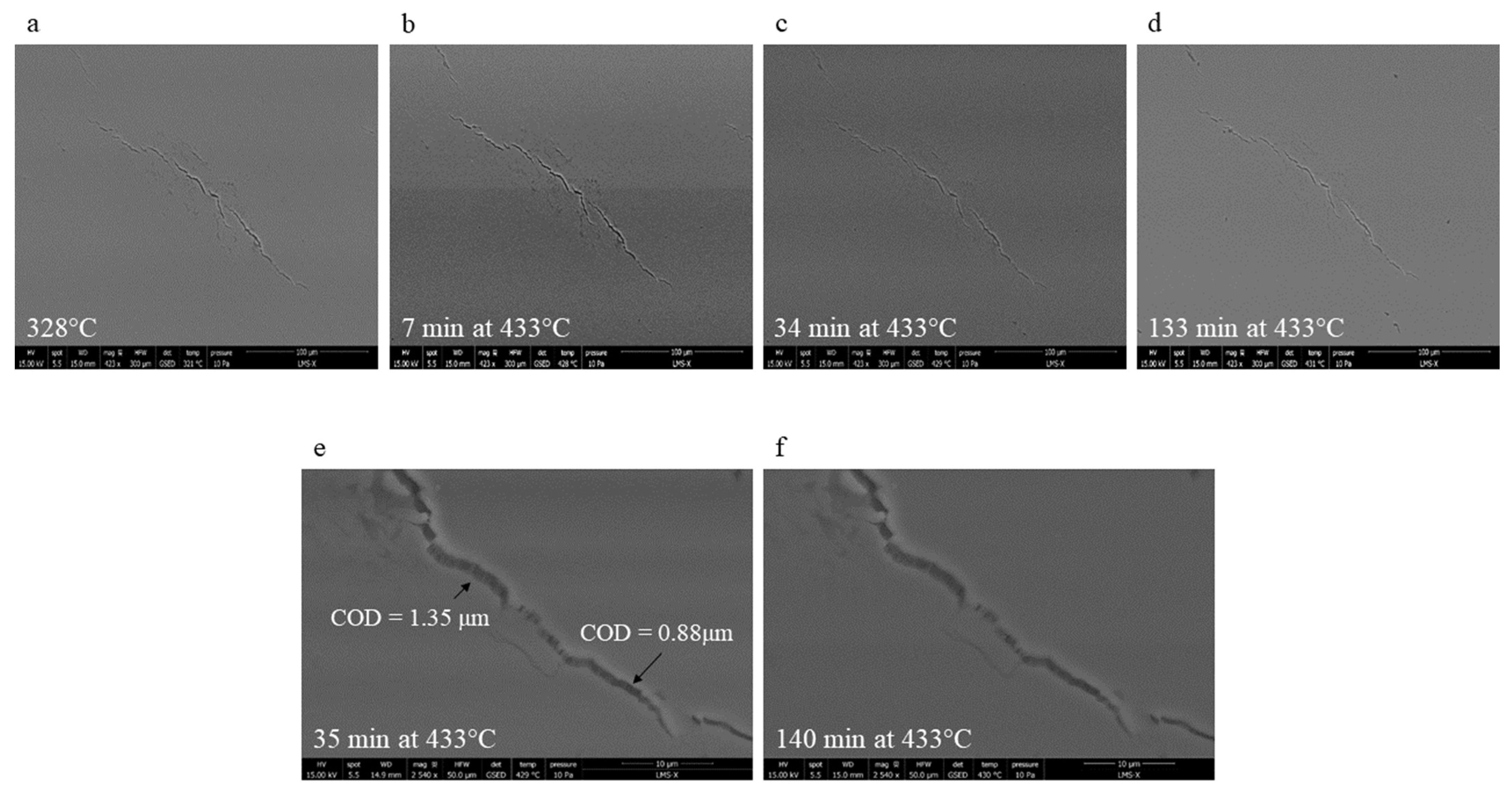
3.3.2. Thermally Induced Damage

The samples issued from ECAP-HT or SPS did not show any thermally induced damage after 1 h annealing at 400 °C, and neither did those issued from ECAP-BP-RT with an initial hardness lower than 91. By contrast, those with a higher hardness formed coalescing microcracks (HV = 127 ± 3.3, Figure 15a), or even regularly spaced macrocracks (HV = 149 ± 3.7, Figure 15b–e) along the ECAP shear plane. In spite of this orientation, these cracks do not exhibit any residual sliding displacements, but rather a crack-opening displacement, COD© which increases with the distance r to the crack tip, generally blunted (Figure 15d).
The presence of closely spaced nano-filaments, 70 to 200 nm in diameter, and up to 7 µm long, bridging the cracks, or detached from one crack face (Figure 15f,g), evoke crazing in cracked polymers. The further away from the crack tip, the longer the bridging filaments. Considering a final filament length, Lf = 7 µm, when it was broken or detached from one crack face, and assuming an initial length L0, of the same order of magnitude as the Al mean grain size, about 70 nm, their ductility at 400 °C is thus as high as 990%, which corresponds to a superplastic regime. Most filaments look straight, but some broken filaments are bent, maybe due to self-weight-induced creep, and some, still adherent to both crack faces, seem to have buckled, maybe due to a decrease in crack opening upon cooling. EDS chemical analysis showed that these filaments are indeed constituted of aluminum. Several such nano-filaments were extracted using a focused ion beam and were observed by TEM (Figure 16). Diffraction analysis showed that even though some curvature of the filaments slightly modifies the diffraction patterns captured at different places along their length, the differences are small enough to conclude that each filament corresponds to an Al single crystal containing dislocations. One of the filaments exhibits a local reduction of its diameter, evocative of a necking zone (Figure 16d).
After machining of the sample back side, in order to reduce its thickness, and thus increase the chance to obtain a through-thickness crack, one of the thermally induced cracks was forced open, allowing SEM observations of a crack face (Figure 15c). The borders of 10–20 µm-wide shallow cavities are decorated (see the red boxes on Figure 15c) by rows of more or less stretched aluminum nano-filaments, sometimes several microns long, and isolated, but most often shorter and not yet separated from the filament bundle delimiting the cavity. This suggests that the Al single crystals nano-filaments are formed by detachment along their grain boundaries from a highly stretched polycrystalline ligament separating neighboring cavities.
The direct observation of thermally induced cracks emerging at the surface of a hard sample issued from ECAP-BP-RT during in situ annealing in a SEM (Figure 17) provided an important element about the cracking mechanism. Some cracks started to emerge at the observed surface at temperatures as low as 328 °C. A careful monitoring of these cracks during the whole temperature ramp up to 400 °C, and the subsequent dwell period failed to reveal any significant increase in their opening. This, as well as the global «mode I-like» aspect of the fracture surface, is consistent with trapped gas pressure as the driving force for their growth: as soon as any point of the front of an internally initiated crack reaches the free surface, the gas escapes, the pressure drops, and the crack cannot develop anymore.
A scenario for the thermally induced cracking of the nanocomposites issued from ECAP-BP-RT, schematically illustrated in Figure 18, is now proposed.
After milling, the relative density of the powder encapsulated in tubes inside the glove box is no more than about 55%. Argon is thus present at the interfaces between loose powder particles. At that stage, the gas-filled «pores» do not have any specific shape or preferential orientation. When the powder is in the entrance channel of the die, the applied compression flattens the cavities. A part of the gas might then exit the powder and flow along the inner surface of the tube, but a part probably remains trapped inside the flattened cavities. The huge shear plastic deformation induced by ECAP transforms the cavities into penny-shaped cracks oriented along the highly sheared plane. Thanks to the overall compressive stress state, enhanced by the back pressure, these cracks are barely open. The nanocavities observed by TEM along some interfaces between former powder particles (Figure 5) might correspond to such «cracks». The pressure that the metal undergoes during ECAP is in equilibrium with that imposed to the trapped gas. If ECAP is performed at room temperature, the trapped gas pressure, P0, can reach 248 MPa, according to numerical simulations of Al powder consolidation by ECAP (in a die with the same geometry as the one used here) made by Hagighi et al. [21].
These simulations took into account some back pressure induced by a copper-made front stopper, but the corresponding value of the BP was not specified, and was probably smaller than in the present study where it reached 313 MPa. The trapped pressure after ECAP-BP-RT is thus likely to be here even higher than 248 MPa (2.48 bars). For ECAP-HT, the peak pressing load is 7 to 10 times smaller than at 20 °C (see Table 1), P0 should thus be 7 to 10 times lower than after ECAP-BP-RT. However, crack opening is less constrained, due to the absence of back pressure.
During annealing, the gas pressure P(T) is temperature-dependent. For a perfect gas, when the temperature rises:
P ( T ) V ( T ) = n R T ,
where V(T) stands for the temperature-dependent volume of a cavity, and n stands for the number of Argon moles inside. If the diffusivity of the gas in aluminum is neglected, n remains constant, so that the gas pressure is expected to rise with the temperature, according to:
P T = P 0   T V 0 T 0 V ( T ) ,
where the subscript 0 denotes the initial state, after ECAP. The increase in the volume of the cavity, due merely to thermal expansion of the matrix during annealing can be estimated as:
V ( T ) = V 0 ( 1 + α A l ( T   -   T 0 ) ) 3 ,
where α A l   = 23.10−6K−1 is the thermal expansion coefficient of aluminum. Inserting T0 = 393 K, and T= 673 K into Equation (3) for annealing at 400 °C yields less than 3% variation in volume, which is negligible. By contrast, due to the rising nominal gas pressure, the crack opens, which substantially increases its volume, and thus, reduces the actual gas pressure. For an elastic matrix, with a temperature-dependent Young’s modulus, E(T), the crack-opening displacement (COD) profile along the face of a penny-shape crack of radius a, is known at any distance r from the crack axis [47]:
C O D ( r , T ) = 8 · P ( T ) · ( 1 υ 2 ) π · E ( T ) a 2 r 2 ,
The maximum opening displacement, at the center of the crack (r = 0), is thus:
C O D m a x ( T ) = 8 · P ( T ) · ( 1 υ 2 ) · a π · E ( T ) ,
The volume inside the open crack can be deduced by integrating COD(r) over r between 0 and a, and over the angular position along the circular crack front, thus yielding:
V ( T ) = 0 2 π 0 a C O D ( r ) · r · d r d θ   =   16 P ( 1 υ 2 ) a 3 3 E ( T ) ,
Inserting V(T) and V0 = V(293) into Equation (2) yields:
P = P 0 E ( T ) T E ( 293 ) T 0 ,
Equation (9) shows that the gas pressure reached upon annealing is proportional to P0. Since P0 was 7 to 10 times smaller after ECAP-HT, the risk of pressure-induced cracking upon annealing was much lower than after ECAP-BP-RT, in accordance with the conclusions of Balog et al. [8] that ECAP should preferentially be performed at high temperature to avoid thermally induced cracking likely to occur only above this processing temperature (since P has to rise above P0 to drive the microcracks further than during ECAP-HT).
After ECAP-BP-RT, according to Equation (9), in an elastic matrix with E(673) ≈ 0.93E(293) [48], the gas pressure inside the crack would reach 1.46 P0 =362 MPa (3.62 bars) at 400 °C, more than enough to propagate cracks, especially considering their multiplicity and interactions. According to Equation (7), C O D m a x would exceed 1 µm for a crack radius of 75 µm, and 5 µm for a radius of 375 µm. These elastic estimates are in the same order of magnitude as the measured lengths of the Al nano-filaments that bridge the cracks. In reality, the viscoplastic flow of aluminum during annealing at 400 °C, evidenced by the blunted crack tips, increases the COD above these values, slightly reducing the trapped gas pressure. A more accurate viscoplastic numerical analysis, which would require (1) a preliminary identification of constitutive equations and (2) taking into account the interactions between multiple cracks, is beyond the scope of this study.
Argon is probably not the only gas participating in thermally induced damage. Balog et al. [8] observed thermally induced cracking of aluminum produced from powder by cold isostatic pressing followed by direct extrusion or by ECAP at various temperatures and back pressures. They used dilatometry to highlight the presence of expanding gases trapped in micropores. According to Nylund and Olefjord [35], these gases would be released by the decomposition of the hydroxide layer present at the surface of Al powder, that is: mostly H2O between 100 and 310 °C, then H2 formed by the reaction between water vapor and aluminum above 310 °C. Note that water vapor and hydrogen release and pressurization (H2 cannot diffuse into the metal unless it dissociates) probably occur during ECAP-HT performed at 380 °C, which can make this process dangerous, in case the front or back plug of the tube is expelled by internal pressure, potentially leading to ignition (as this occurred once during this study). The release of these gases might also partly explain the cracking issues encountered during ECAP-HT. Several examples of «hydrogen blisters» (that is: near-surface cracks due to trapped hydrogen) in conventional Al alloys formed during casting or heat treatments [49,50,51] can be found in the literature.

3.4. Comparison of the Consolidation Processes on Practical Aspects

After the point-by-point comparison of the three consolidation processes in terms of microstructure, mechanical properties and thermal stability of the produced nanocomposites, a more practical comparison, in the perspective of their potential industrialization is now proposed.
ECAP-BP-RT is much more demanding in terms of necessary loads than ECAP-HT or SPS, and it requires a more complex device, with two actuators. This can hinder the scaling up of this technique. ECAP-BP consolidation at high temperature, as practiced by several teams [6,19,20,52], can however reduce the required loads, although with additional costs and a more complex device.
As concerns the volume of material obtained after consolidation, an extensive literature review shows that most laboratory-scale ECAP dies have channels at most 20 mm in diameter, or 20 mm × 20 mm large, and accept less than 110 mm-long specimens. The volume of uniformly consolidated powder after the removal of the tube, including its front and back plugs, is thus insufficient for many industrial applications. A few up-scaled ECAP dies able to produce billets up to 100 mm × 100 mm × 300 mm exist [53], but it is not clear whether these facilities include a second actuator for back pressure. On the other hand, a few industrial SPS facilities currently allow specimens up to 350 mm in diameter and more than 250 mm in height to be obtained, provided that thermal gradients in the sample are minimized, which is not so easy to achieve [54].
For the PIT-ECAP process, powder encapsulation in non-reusable tubes adds significant time (for machining the tubes before and after ECAP) as well as costs (for metal purchase and machining) while SPS does not require it. Gas pressure build up inside a closed tube during ECAP-HT also induces potential hazard, especially if the amount of powder is larger than in laboratory experiments, because part of this gas is hydrogen. A solution might be to just wrap the powder in an Al foil and insert it directly into the ECAP die, as a few teams do [6,19,51]. This might allow trapped gases to escape more easily than in a closed tube, but also increase the oxidation and hydration of the powder, in contact with moist air, especially during ECAP-HT.
Due to the number of passes necessary to achieve a good densification, ECAP consolidation requires more time and labor than SPS, which has the additional merit to include the powder degassing step, necessary for a good thermal stability of the material.
While SPS consolidation does not induce a significant texture, ECAP consolidation produces textured materials, whose properties will thus be anisotropic. This should complicate the mechanical design and forming of pieces from ECAPed billets.
Overall, on a practical point of view, the SPS consolidation of Al matrix nanocomposites seems more efficient and likely to develop at an industrial scale than ECAP consolidation.

4. Conclusions

Ultrafine-grained Al matrix nanocomposites reinforced with Al2O3 nanoparticles were produced from milled powders, either by ECAP at 20 °C with 88 to 315 MPa back pressure (ECAP-BP-RT) or at 380 °C without any back pressure (ECAP-HT), or by spark plasma sintering (SPS). Their microstructures, mechanical properties (compression, hardness and sliding wear), and thermal stabilities (thermally induced softening and cracking) were compared. The following conclusions were reached.
  • ECAP-HT without any back pressure could not yield macro-crack-free samples from hard powders (composite hardness higher than 55).
  • The application of a back pressure allowed harder powders to be consolidated without macroscale damage. However, ECAP-induced cracking was still observed for composites with a hardness above 91 (Al mean grain size below 218 nm).
  • Macrocrack-free samples with a hardness as high as 139 were obtained by SPS (Al mean grain size slightly above 65 nm).
  • The samples hardnesses correlate very well with their mean Al grain size without a clear and direct impact of the nanoparticles weight fraction. However, due to Zener pinning, these particles, if properly dispersed, prevent grain growth during ECAP-HT, SPS, or static annealing, allowing the hardness to remain stable up to 500 °C.
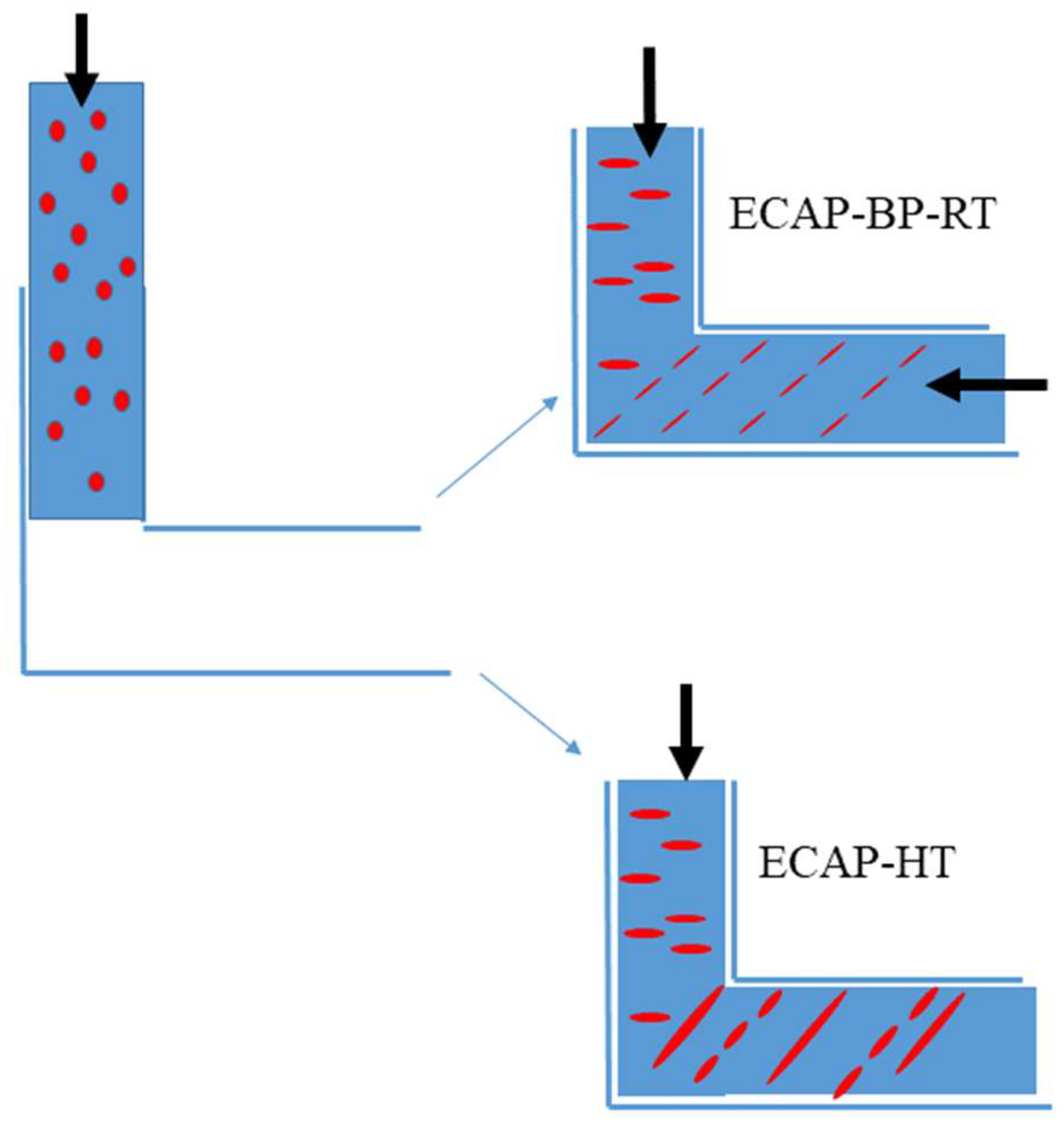
  • The flow stress in compression of the best nanocomposites issued from ECAP-BP-RT (Al-99.5%, 2% Al2O3 milled 4 h at 225 rpm, 2 ECAP passes) was approximately four times higher than that of bulk Al 1050, while that of those issued from SPS (Al-99.9%, 2% Al2O3 milled 16 h at 225 rpm, SPS at 535 °C, under 125 MPa) was nine times higher than that of Al 1050, and comparable to that of Al 2024-T6.
  • Some of the nanocomposites issued from ECAP-BP-RT were nearly as resistant to sliding wear as Al 5083 and more resistant than Al 7075-T6.
  • While the samples consolidated at high temperatures (by ECAP-HT or SPS) showed a good stability during 1 h static annealing at 400 °C, those consolidated by ECAP at room temperature were prone to thermally induced softening and cracking, which was clearly related to trapped and pressurized gases.
  • Even though in the literature about the synthesis of Al matrix nanocomposites by ECAP from powder mixtures, preliminary degassing and vacuum encapsulation of the powder are not considered as necessary, the present study suggests that it is indeed preferable in order to avoid thermally induced cracking upon subsequent high temperature exposure, and also to make ECAP-HT more successful. Powder consolidation should preferentially be performed at high temperature, to avoid thermally induced cracking, likely to occur only above this processing temperature.
  • The fact that the SPS process starts with the hot vacuum degassing of the powder is clearly an advantage for the thermal stability of the consolidated materials. This powder consolidation process is also much more time- and cost-efficient than ECAP, and more promising for industrial implementation. Nonetheless, it requires a careful optimization of its parameters, in order to avoid the presence of non-bonded powder grain clusters while minimizing the growth of the Al grains, as well as that of the iron-rich intermetallic particles, detrimental to ductility and fatigue resistance of Al alloys.

Author Contributions

Conceptualization, V.D., A.L.-G.-G., M.N. and R.M., data curation, V.D. and A.L.-G.-G., formal analysis, A.L.-G.-G. and V.D., funding acquisition, V.D., investigation, A.L.-G.-G., V.D., A.T., S.H., M.N., J.B. and B.V., methodology, V.D. and A.L.-G.-G., project administration, V.D., resources, R.M., J.B. and B.V., supervision, V.D., validation, V.D. and A.L.-G.-G., visualization, V.D. and A.L.-G.-G., writing—original draft, V.D., writing—review and editing, all authors. All authors have read and agreed to the published version of the manuscript.

Funding

The financial support for the NanoCal project was provided in the framework of agreement N° 2020 65 0055 between the Ministry of Defence, Agence de l’innovation de Défense (AID), and Ecole Polytechnique.

Data Availability Statement

The data presented in this study are available upon reasonable request from the corresponding author.

Acknowledgments

Sandrine Tusseau-Nenez, from the Diffrax Platform at Ecole Polytechnique, is gratefully acknowledged for the X-ray diffraction measurements of the mean grain sizes. Eva Heripre and Maxime Vallet from Equipex Matmeca at Ecole Centrale, University Paris-Saclay are gratefully acknowledged for the FIB extraction and TEM observations of Al nano-filaments bridging thermally induced cracks.

Conflicts of Interest

The authors declare no conflict of interest.

References

  1. Goyal, A. Comportement Mécanique d’un Alliage d’aluminium à Grains Ultrafins. Analyse et Modélisation du Rôle Exacerbé des Joints de Grains. Ph.D. Thesis, École Polytechnique, Palaiseau, France, 29 November 2018. [Google Scholar]
  2. Illgen, C.; Bohne, B.; Wagner, M.F.X.; Frint, P. Thermal stability of SPD-processed aluminum alloys—Internal friction as an indication for recovery, recrystallization and abnormal grain growth. J. Mater. Res. Technol. 2022, 17, 1752–1759. [Google Scholar] [CrossRef]
  3. Hamilton, N.E.; Ferry, M. Grain growth in a nanocrystalline Al-Sc alloy. Mater. Trans. 2004, 45, 2264–2271. [Google Scholar] [CrossRef]
  4. Chuvil’deev, V.N.; Shadrina, I.S.; Nokhrin, A.V.; Kopylov, V.I.; Bobrov, A.A.; Yu Gryaznov, M.; Shotin, S.V.; Yu Tabachkova, N.; Chegurov, M.K.; Melekhin, N.V. An investigation of thermal stability of structure and mechanical properties of Al-0.5MgeSc ultrafine-grained aluminum alloys. J. Alloys Compd. 2020, 831, 154805. [Google Scholar] [CrossRef]
  5. Bate, P. The effect of deformation on grain growth in Zener pinner systems. Acta Mater. 2001, 49, 1453–1461. [Google Scholar] [CrossRef]
  6. Kubota, M.; Wu, X.; Xu, W.; Xia, K. Mechanical properties of bulk aluminum consolidated from mechanically milled particles by back pressure equal channel angular pressing. Mater. Sci. Eng. A 2010, 527, 6533–6536. [Google Scholar] [CrossRef]
  7. Paryar, A.; Toth, L.; Kailas, S.V.; Peltier, L. Imparting high-temperature grain stability to an Al-Mg alloy. Scr. Mater. 2021, 190, 141–146. [Google Scholar] [CrossRef]
  8. Balog, M.; Frantisek, S.; Otto, B.; Requena, G. ECAP versus direct extrusion -Techniques for consolidation of ultra-fine Al particles. Mater. Sci. Eng. A 2009, 504, 1–7. [Google Scholar] [CrossRef]
  9. Haghighi, R.D.; Jenabali Jahromi, S.A.; Moresedgh, A.; Khorshid, M.T. A Comparison Between ECAP and Conventional Extrusion for Consolidation of Aluminum Metal Matrix Composite. J. Mater. Eng. Perform. 2012, 21, 1885–1892. [Google Scholar] [CrossRef]
  10. Casati, R.; Vedani, M. Metal Matrix Composites Reinforced by Nano-Particles—A review. Metals 2014, 4, 65–83. [Google Scholar] [CrossRef]
  11. Chak, V.; Chattopadhyay, H.; Dora, T.L. A review on fabrication methods, reinforcements and mechanical properties of aluminum matrix composites. J. Manuf. Proc. 2020, 56, 1059–1074. [Google Scholar] [CrossRef]
  12. Casati, R.; Fabrizi, A.; Timelli, G.; Tuissi, A.; Vedani, M. Microstructural and Mechanical Properties of Al-Based Composites Reinforced with In-Situ and Ex-Situ Al2O3 Nanoparticles. Adv. Eng. Mater. 2016, 18, 550–558. [Google Scholar] [CrossRef]
  13. Bera, S.G.; Chowdhury, S.G.; Estrin, Y.; Manna, I. Mechanical properties of Al7075 alloy with nano-ceramic oxide dispersion synthesized by mechanical milling and consolidated by equal channel angular pressing. J. Alloys Compd. 2013, 548, 257–265. [Google Scholar] [CrossRef]
  14. Musa, M.Š.; Schauperl, Z. ECAP—New consolidation method for production of aluminum matrix composites with ceramic reinforcement. Process. Appl. Ceram. 2013, 7, 63–68. [Google Scholar] [CrossRef]
  15. Zare, H.; Jahedi, M.; Reza Toroghinejad, M.; Meratian, M.; Knezevic, M. Microstructure an dmechanical properties of carbon nanotubes reinforced aluminum matrix composites synthesized via equal-channel angular pressing. Mater. Sci. Eng. A 2016, 670, 205–216. [Google Scholar] [CrossRef]
  16. Bongale, A.M.; Kumar, S. Equal channel angular pressing of powder processed Al6061/SiC nano metal matrix composites and study of its wear properties. Mater. Res. Express 2018, 5, 035002. [Google Scholar] [CrossRef]
  17. Nagasekhar, A.V.; Tick-Hon, Y.; Ramakanth, K.S. Mechanics of single pass equal channel angular extrusion of powder in tubes. Appl. Phys. A 2006, 85, 185–194. [Google Scholar] [CrossRef]
  18. Xia, K. Consolidation of Particles by Severe Plastic Deformation: Mechanism and Applications in Processing Bulk Ultrafine and Nanostructured Alloys and Composites. Adv. Eng. Mater 2010, 8, 724–729. [Google Scholar] [CrossRef]
  19. Goussous, S.; Xu, W.; Wu, X.; Xia, K. Al–C nanocomposites consolidated by back pressure equal channel angular pressing. Compos. Sci. Technol. 2009, 69, 1997–2001. [Google Scholar] [CrossRef]
  20. Hanna, J.A.; Baker, I. Effects of confining pressure on flaw formation during the consolidation of ductile powders by angular extrusion. Mater. Sci. Eng. A 2012, 536, 24–32. [Google Scholar] [CrossRef]
  21. Hagighi, R.D.; Jarohmi, A.J.; Jarohmi, B.E. Simulation of powder in tube compaction using equal channel angular extrusion. J. Mater. Eng. Perform. 2012, 21, 143–152. [Google Scholar] [CrossRef]
  22. Elkhodary, K.I.; Salem, H.G.; Zikry, M.A. Equal Channel Angular Pressing of Canned 2124-Al Compacts: Processing, Experiments, and Modeling. Met. Mater. Trans. A 2008, 39, 2184–2192. [Google Scholar] [CrossRef]
  23. Tuncay, M.; Nguyen, L.; Hendrickx, P.; Brochu, M. Evaluation of the particle bonding for Aluminum sample produced by spark plasma sintering. J. Mater. Eng. Perform. 2016, 25, 4529. [Google Scholar] [CrossRef]
  24. Le, G.M.; Godfrey, A.; Hansen, N. Structure and strength of aluminum with sub-micrometer /micrometer grain size prepared by spark plasma sintering. Mater. Design 2013, 49, 360–367. [Google Scholar] [CrossRef]
  25. Kushwaha, A.K.; Maccione, R.; John, M.; Lanka, S.; Misra, M.; Menezes, P.L. Influence of Cryomilling on Crystallite Size of Aluminum Powder and Spark Plasma Sintered Component. Nanomaterials 2022, 12, 551. [Google Scholar] [CrossRef]
  26. Kushwaha, A.K.; Misra, M.; Menezes, P.L. Manufacturing Bulk Nanocrystalline Al-3Mg Components Using Cryomilling and Spark Plasma Sintering. Nanomaterials 2022, 12, 3618. [Google Scholar] [CrossRef]
  27. Soares, E.; Bouchonneau, N.; Alves, E.; Alves, K.; Araújo Filho, O.; Mesguich, D.; Chevallier, G.; Laurent, C.; Estournès, C. Microstructure and Mechanical Properties of AA7075 Aluminum Alloy Fabricated by Spark Plasma Sintering (SPS). Materials 2021, 14, 430. [Google Scholar] [CrossRef]
  28. Kwon, H.; Park, D.H.; Park, Y.; Silvain, J.F.; Kawasaki, A.; Park, Y. Spark Plasma Sintering Behavior of Pure Aluminum Depending on Various Sintering Temperatures. Met. Mater. Int. 2010, 16, 71–75. [Google Scholar] [CrossRef]
  29. Sweet, G.A.; Brochu, M.; HexemerJr, R.L.; Donaldson, I.W.; Bishop, D.P. Microstructure and mechanical properties of air atomized aluminum powder consolidated via spark plasma sintering. Mater. Sci. Eng. A 2014, 608, 273–282. [Google Scholar] [CrossRef]
  30. Kubota, M. Properties of nano-structured pure Al produced by mechanical grinding and spark plasma sintering. J. Alloys Compd. 2007, 434–435, 294–297. [Google Scholar] [CrossRef]
  31. Molodova, X.; Gottstein, G.; Hellmig, R.J. On the Thermal Stability of ECAP Deformed FCC Metals. Mater. Sci. Forum 2008, 584–586, 259–264. [Google Scholar]
  32. Molodova, X.; Gottstein, G. Annealing Behavior of ECAP deformed Aluminum Alloy 3103. Mater. Sci. Forum 2008, 584–586, 944–949. [Google Scholar] [CrossRef]
  33. Bommareddya, A.; Quadira, M.Z.; Ferry, M. Time and temperature regime of continuous grain coarsening in an ECAP-processed Al(0.1 wt.% Sc) alloy. J. Alloys Compd. 2012, 527, 145–151. [Google Scholar] [CrossRef]
  34. Cabibbo, M.; Evangelista, E.; Latini, V. Thermal stability study on two aluminum alloys processed with equal channel angular pressing. J. Mater. Sci. 2004, 39, 5659–5667. [Google Scholar] [CrossRef]
  35. Nylund, A.; Olefjord, I. Degassing of USGA-atomized Al5Mn6Cr powder after exposure to a humid atmosphere. Mater. Sci. Eng. A 1991, 134, 1225–1228. [Google Scholar] [CrossRef]
  36. Beausir, B.; Fundenberger, J.J. Analysis Tools for Electron and X-ray Diffraction, ATEX-Software, Université de Lorraine-Metz. 2017. Available online: www.atex-software.eu (accessed on 4 January 2023).
  37. Lutterotti, L. Maud: A Rietveld Analysis Program Designed for the Internet and Experiment Integration. Acta Crystallogr. A 2020, 56, s54. [Google Scholar] [CrossRef]
  38. De Keijser, T.H.; Langford, J.I.; Mittemeijer, E.J.; Vogels, A.B.P. Use of the Voigt function in a single-line method for the analysis of X-ray diffraction line broadening. J. Appl. Crystallogr. 1982, 15, 308–314. [Google Scholar] [CrossRef]
  39. Delhez, R.; De Keijser, T.H.; Langford, J.I.; Louër, D.; Mittemeijer, E.J.; Sonneveld, E.J. Crystal imperfection broadening and peak shape in the Rietveld method. In The Rietveld Method; Young, R.A., Ed.; Oxford University Press: Oxford, UK, 1993; pp. 132–166. [Google Scholar]
  40. Rauch, E.F.; Véron, M. Automated Crystal Orientation and Phase Mapping in TEM. Mater. Charact. 2014, 98, 1–9. [Google Scholar] [CrossRef]
  41. Arzaghi, M.; Beausir, B.; Toth, L. Contribution of non-octahedral slip to texture evolution of fcc polycrystals in simple shear. Acta Mater. 2009, 57, 2440–2453. [Google Scholar] [CrossRef]
  42. Casati, R. Aluminum Matrix Composites Reinforced with Alumina Nanoparticles. In Springer Briefs in Applied Sciences and Technology; Springer: Berlin/Heidelberg, Germany, 2016; ISSN 2191-530X. [Google Scholar]
  43. Kam, K.M.; Zeng, L.; Zhou, Q.; Tran, R.; Yang, J. On assessing spatial uniformity of particle distributions in quality control of manufacturing processes. J. Manuf. Syst. 2012, 32, 154–166. [Google Scholar] [CrossRef]
  44. Hannard, F.; Castin, S.; Maire, E.; Mokso, R.; Pardoen, T.; Simar, A. Ductilization of aluminum alloy 6056 by friction stir processing. Acta Mater. 2017, 130, 121–136. [Google Scholar] [CrossRef]
  45. Li, M.; Goyal, A.; Doquet, V.; Couzinié, J.P. Ultrafine versus coarse grained Al 5083 alloys: From low-cycle to very-high-cycle fatigue. Int. J. Fatigue 2019, 121, 84–97. [Google Scholar]
  46. Brach, S.; Collet, S. Criterion for critical junctions in elastic-plastic adhesive wear. Phys. Rev. Lett. 2021, 127, 185501. [Google Scholar] [CrossRef]
  47. Sneddon, I.N. The distribution of stress in the neighborhood of a crack in an elastic solid. Proc. R. Soc. A 1946, 187, 229–260. [Google Scholar]
  48. Gerlich, D.; Fisher, E.S. The high temperature elastic moduli of aluminum. J. Phys. Chem. Solids 1969, 30, 1197–1205. [Google Scholar] [CrossRef]
  49. Hu, X.G.; Zhu, Q.; Midson, S.P.; Atkinson, H.V.; Dong, H.B.; Zhang, F.; Kang, Y.L. Blistering in semi-solid die casting of aluminum alloys and its avoidance. Acta Mater. 2017, 124, 446–455. [Google Scholar] [CrossRef]
  50. Diehl, D.; Schneider, E.L.; Rosauro Clarke, T.G. Formation of hydrogen blisters during the solution treatment for aluminum alloys. Tecnol. Metal. Mater. Min. 2021, 18, e2374. [Google Scholar] [CrossRef]
  51. Toda, H.; Hidakaa, T.; Kobayashi, M.; Uesugi, K.; Takeuchi, A.; Horikawa, K. Growth behavior of hydrogen micropores in aluminum alloys during high-temperature exposure. Acta Mater. 2009, 57, 2277–2290. [Google Scholar] [CrossRef]
  52. Wu, X.; Xu, W.; Xia, K. Pure aluminum with different grain size distributions by consolidation of particles using equal-channel angular pressing with back pressure. Mater. Sci. Eng. A 2008, 493, 241–245. [Google Scholar] [CrossRef]
  53. Srinivasan, R.; Cherukuri, B.; Chaudhury, P. Scaling up of Equal Channel Angular Pressing (ECAP) for the Production of Forging Stock. Mater. Sci. Forum 2006, 503, 371–378. [Google Scholar] [CrossRef]
  54. Monchoux, J.P.; Couret, A.; Durand, L.; Voisin, T.; Trzaska, Z.; Thomas, M. Elaboration of Metallic Materials by SPS: Processing, Microstructures, Properties, and Shaping. Metals 2021, 11, 322. [Google Scholar] [CrossRef]
Figure 1. Initial morphologies of (a) the Al-99.9 powder, (b) the Al-99.9 powder, and (c) distribution of the effective diameter of the alumina nanoparticles measured by DLS.
Metals 13 00825 g001
Figure 2. Evolution of (a) the chamber pressure, (b) the temperature and compressive stress, and (c) the actuator displacement during SPS consolidation of Al + 2% Al2O3 nanoparticles powder, milled for 16 h at 225 rpm.
Metals 13 00825 g002
Figure 3. Microstructures and pole figures of the first pair of samples mentioned in Table 1 (un-milled Al-99.5%): (ac) after 1 pass of ECAP-HT (HV = 41.7), (df) after 1 pass of ECAP-BP-RT (HV = 64.6). The red squares on (b) show triangular cavities at triple points, typical of grain boundary sliding.
Metals 13 00825 g003
Figure 4. Microstructure and macro or microscale damage in the second pair of samples mentioned in Table 1 (Al + 2% Al2O3 nanoparticles, milled 4 h at 225 rpm): (a,b) after 2 passes of ECAP-HT (HV = 92), and (c,d) after 2 passes of ECAP-BP-RT (HV = 91).
Metals 13 00825 g004
Figure 5. TEM observations of an Al-99.5%+ 2% Al2O3 nanocomposite, milled 4 h at 225 rpm, after yeo passes of ECAP-BP-RT (HV = 91). (a) TEM image (c) TEM image and corresponding: (b) pole figures, (d) phase mapping, and (e) inverse pole figure, IPF-Z.
Metals 13 00825 g005
Figure 6. TEM-EDS chemical analyses of a Al-99.5% + 2% Al2O3 nanocomposite, milled 4 h at 225 rpm after 2 passes of ECAP-BP-RT (HV = 91). (a) TEM images and corresponding mappings of (c) oxygen atomic%, (d) aluminum atomic%, (e) iron atomic%, and (b) superimposed maps.
Metals 13 00825 g006
Figure 7. (a) Macroscale aspect, (b,c) SEM, (d) TEM observations, (e) phase mapping, (f) local inverse pole figure IPF-Z, and (g) local pole figures of an Al-99.5% + 2% Al2O3 nanocomposite, milled 16 h at 225 rpm, after 1 pass of ECAP-BP-RT (HV = 149).
Metals 13 00825 g007
Figure 8. TEM-EDS chemical analyses of an Al-99.5% + 2% Al2O3 nanocomposite, milled 16 h at 225 rpm after 1 pass of ECAP-BP-RT (HV = 149). (a) TEM image and corresponding maps of (c) oxygen atomic%, (d) aluminum atomic%, (e) iron atomic%, and (b) superimposed maps.
Metals 13 00825 g008
Figure 9. (a) SEM observation, (b) EBSD mappings, and (c) pole figures of an Al-99.9% + 2% Al2O3 nanocomposite, milled 4 h at 225 rpm, consolidated by SPS at 550 °C during 5 min, under 75 MPa (HV = 54).
Metals 13 00825 g009
Figure 10. SEM observations of nanocomposites consolidated by SPS from Al-99.9% + 2% Al2O3 milled 16 h at 225 rpm. (a) sample SPS16h-0; (b) sample SPS16h-1; (c) sample SPS16h-2; (d)sample SPS16h-3; (e,f) sample SPS16h-5.
Metals 13 00825 g010
Figure 11. TEM observations, phases map, and pole figures on sample SPS0 consolidated by SPS from Al-99.9% + 2% Al2O3 milled 16 h at 225 rpm. (a) TEM image and corresponding (b) phase map, (c) inverse pole figure, and (d) local pole figure.
Metals 13 00825 g011
Figure 12. Compared behavior of nanocomposites produced by SPS or ECAP-BP-RT and of bulk Al 1050 in compression. (a) True stress–true strain curves, (b) initial and final aspect of a sample.
Metals 13 00825 g012
Figure 13. Correlation between the microhardness and mean grain size of the nanocomposites and bulk Al 1050.
Metals 13 00825 g013
Figure 14. (a) Percentage drop in hardness after 1 h at 400 °C versus the initial hardness and (b) compared temperature evolutions of the hardness of ultrafine grained 5083 and 6082 alloys from billets ECAPed at room temperature, and those of nanocomposites from the present study.
Metals 13 00825 g014
Figure 15. Thermally induced cracking along the ECAP shear plane in (a) Al+ 2% NP milled 8 h at 225 rpm, 4 passes ECAP-BP-RT (HV = 127 ± 3.3), and (be) Al-99.5% + 2% NP milled 16 h at 225 rpm, 1 passe ECAP-BP-RT (HV = 149 ± 3.7). Pictures (d,e) show a blunted crack tip and bridging nanofilaments, picture (c) shows one face of such a thermally induced crack after opening. Nano-filaments are visible in the red boxes.
Metals 13 00825 g015
Figure 16. (a) Selection of a pair of Al nano-filaments bridging a thermally induced crack (same specimen as in Figure 7) (b) FIB extraction, and (ce) TEM observations.
Metals 13 00825 g016
Figure 17. Surface monitoring of thermally induced cracks during in situ annealing in the SEM (ad) 4 snapshots of the same area at different stages. (e,f) two snapshots of a different area at different stages.
Metals 13 00825 g017
Figure 18. Scenario for thermally induced cracking.
Metals 13 00825 g018
Table 1. Example of process parameters and outcome of extrusions, for two pairs of specimens with similar composition and milling conditions, produced either by ECAP-BP-RT, or ECAP-HT.
PowderMillingECAP T °CPressing Load (kN)Back Pressure (MPa)Number of PassesHVDensity (%)Mean Grains Size (µm)
Al-99.5%No37550≈0141.7 ± 0.698.5 ± 0.52.5
203508864.6 ± 1.198.5 ± 0.51.16
Al-99.5% + 2%NP4 h38560≈0292 ± 3.7 0.220
225 rpm2056225091 ± 3.294.2 ± 0.50.218
Table 2. Parameters of the SPS consolidation of Al-99.9% + 2% NP and results.
Sample Ref & MillingTemperature EvolutionCompressive Stress EvolutionDensityHardness
SPS4hRamp to 550 °C in 6 min10 MPa until 550 °C96.5%54.1 ± 1.4
4 h, 225 rpm5 min dwell periodThen 75 MPa within 2 min
Φ = 20 mm1 min power ramp down3 min dwell at 75 MPa
SPS16h-0Ramp to 550 °C in 6 min10 MPa until 550 °C100%126.5 ± 2.2
16 h, 225 rpm8 min dwell periodThen 75 MPa within 2 min
Φ = 20 mm1 min power ramp down6 min dwell at 75 MPa
SPS16h-1Ramp to 540 °C in 5 min,15 MPa until 540 °C,96.3%132.2 ± 2.3
16 h, 225 rpmThen to 550 °C in 1 minThen 75 MPa within 2 min
Φ = 15 mm3 min dwell at 550 °C3 min dwell at 75 MPa
<10 s power ramp down
SPS16h-2Ramp to 540 °C in 5 min,15 MPa until 540 °C,95.8%135.4 ± 2.5
16 h, 225 rpmThen to 550 °C in 1 minThen 75 MPa within 1 min
Φ = 15 mm2 min dwell at 550 °C2 min dwell at 75 MPa
<10 s power ramp down
SPS16h-3Ramp to 540 °C in 5 min,15 MPa until 540 °C,96.7%137.9 ± 2.5
16 h, 225 rpmThen to 550 °C in 1 minThen 100 MPa within 1 min
Φ = 15 mm2 min dwell at 550 °C2 min dwell at 100 MPa
<10 s power ramp down
SPS16h-5Ramp to 525 °C in 5 min,15 MPa until 535 °C,95.9%139.5 ± 2.6
16 h, 225 rpmThen to 535 °C in 1 minThen 125 MPa within 1 min
Φ = 15 mm2 min dwell at 535 °C2 min dwell at 125 MPa
<10 s power ramp down
Table 3. Size of the iron-rich intermetallic particles.
SampleMean Size (µm)Max Size (µm)
Bulk Al 10501.187.08
Al 99.5%, unmilled
1 pass ECAP-BP-RT
--
Al-99.5% + 2% NP, milled 16 h @ 225 rpm0.251.08
2 passes ECAP-HT
Al-99.9% + 2% NP, milled 16 h @ 225 rpm0.352.05
SPS4h, 5 min @550 °C + overheating
Al-99.9% + 2% NP, milled 4 h @ 225 rpm1.605.71
SPS16h-0, 8 min @550 °C + overheating
Al-99.9% + 2% NP, milled 16 h @ 225 rpm
SPS16h-1, 4 min @550 °C
0.321.15
Table 4. Influence of the nanoparticles on Al grains refinement for ECAP-HT.
Al-99.5%Al-99.5% + 2% Al2O3
4 h milling, 225 rpm
2 ECAP passes at 380 °C
1 µm218 nm
HV = 69 ± 1.4HV = 92 ± 3.7
Al-99.5%Al-99.5% + 5% Al2O3
16 h milling, 225 rpm
2 ECAP passes at 380 °C
132 nm63 nm
HV = 101 ± 3.5HV = 148 ± 3.3
Table 5. Influence of the nanoparticles on Al grains refinement for ECAP-BP-RT.
Al-99.9% + 2% Al2O3Al-99.9% + 4% Al2O3Al-99.9% + 6% Al2O3
4 h milling, 160 rpm
4 ECAP passes at 20 °C
1.16 µm1.16 µm1.08 µm
HV = 63.9 ± 2.2HV = 66 ± 2.6HV = 65 ± 2.4
Table 6. Results of the sliding wear tests.
SamplesHardnessFriction CoefficientWear Rate (g/m)
Bulk Al 5083, strain hardened92 ± 1.20.490.8 × 10−3
Bulk Al 7075-T6141 ± 1.50.431.7 × 10−3
Al-99.9% + 4% NP, milled 4 h @195 rpm
4 passes ECAP-BP-RT
64 ± 2.10.441.2 × 10−3
Al-99.9% + 2% NP, milled 4 h @160 rpm
4 passes ECAP-BP-RT
63.9 ± 2.20.804.8 × 10−3
Al-99.9% + 4% NP, milled 4 h @ 160 rpm
4 passes ECAP-BP-RT
66 ± 2.60.782.0 × 10−3
Al-99.9% + 6% NP, milled 4 h @ 160 rpm
4 passes ECAP-BP-RT
65 ± 2.40.461.0 × 10−3
Al-99.9% + 2% NP, milled 16 h @ 225 rpm
SPS 550 °C, 8 min, 75 MPa
126.5 ± 2.20.461.8 × 10−3
Table 7. Outcome of 1 h static annealing at 400 °C in terms of hardness drop, and thermally induced damage.
Samples Number
Composition
Milling Conditions
ECAP Process
Initial
Hardness
Post Annealing
Hardness
% Drop in
Hardness
Annealing-Induced Damage
1: Al-99.5%,
no milling
2 passes, BP-RT
66 ± 1.147 ± 1.128.7None
2: Al-99.9% + 2% NP
4 h @ 160 rpm
4 passes, BP-RT
63.9 ± 2.241 ± 2.036.6None
3: Al-99.9% + 4% NP
4 h @ 160 rpm
4 passes, BP-RT
66 ± 2.643 ± 2.235.2None
4: Al-99.5%,
4 h @ 225 rpm
2 passes, 386 °C
69 ± 2.568 ± 2.40.01None
5: Al-99.5% + 2% NP
4 h @ 225 rpm
2 passes, BP-RT
91 ± 3.292 ± 3.10None
6: Al-99.5% + 2% NP
4 h @ 225 rpm
2 passes, 386 °C
92 ± 3.792 ± 3.40None
7: Al-99.9% + 2% NP
8 h @ 225 rpm
4 passes, BP-RT
127 ± 3.3115 ± 3.49.4Microcracks
8: Al-99.9% + 2% NP
8 h @ 225 rpm
2 passes, BP-RT
139 ± 3.6129 ± 3.37.2Microcraks
9: Al-99.5% + 2% NP
16 h @ 225 rpm
1 pass, BP-RT
149 ± 3.7144 ± 3.43.6Severe craking
10: Al-99.9% + 2% NP
16 h @ 225 rpm
1 pass, BP-RT
153 ± 1.9150 ± 2.02Severe cracking
11: Al-99.9% + 2% NP
16 h @ 225 rpm
SPS 550 °C, 8 min, 75 MPa
126.5 ± 2.2133 ± 2.70None
12: Al-99.9% + 2% NP
16 h @ 225 rpm
SPS 550 °C, 3 min, 100 MPa
137.9 ± 2.5137 ± 2.30None
Disclaimer/Publisher’s Note: The statements, opinions and data contained in all publications are solely those of the individual author(s) and contributor(s) and not of MDPI and/or the editor(s). MDPI and/or the editor(s) disclaim responsibility for any injury to people or property resulting from any ideas, methods, instructions or products referred to in the content.

