Article

Buckling Analysis of Conical Shell Openings with Reinforced Perimeter Walls under Uniform External Pressure

School of Mechanical Engineering, Jiangsu University of Science and Technology, Zhenjiang 212003, China
*
Author to whom correspondence should be addressed.
Metals 2023, 13(5), 824; https://doi.org/10.3390/met13050824
Submission received: 2 March 2023 / Revised: 17 April 2023 / Accepted: 18 April 2023 / Published: 23 April 2023

Abstract

:
In this paper, the effects of opening parameters and reinforcing wall parameters on the bearing capacity of conical shells with an opening were investigated. Under the condition that the conical shells with an opening were all reinforced with walls, the opening position and the inclination angle of the reinforced wall were selected as variables to be used in the numerical analysis and hydrostatic pressure test. The nonlinear numerical buckling load and the test results were compared. The difference was within 17.8%, which verified the rationality of the finite element model. The final buckling mode obtained by numerical calculation of the measured data was in good agreement with the real collapse mode obtained by hydraulic testing of the actual model. Then the influence of the opening position and inclination angle of the reinforcing wall on the buckling load of the conical shell under different opening rates was analyzed in detail.

1. Introduction

As a common pressure vessel, the pressure cabin is the core structural component to ensure the safety of internal equipment. The design and manufacture of the pressure shell structure are very important. Its strength and stability are the issues that need to be focused on [1]. A rotary shell structure with high load-bearing efficiency has the advantage of good streamline. It is widely used in aviation, marine, and other engineering fields [2]. The conical pressure shell, as one of the typical reverting pressure shells, is widely used in the tail section of marine submersibles and submarines, the main part of deep-sea workstations, aerospace return capsules, pressure vessels, and other structures [3,4,5,6].
Many parameters affect the buckling performance of conical shells. B.S. Golzan et al. [7] studied the nonlinear response of truncated conical shells; shallow conical caps subjected to external uniform pressure are discussed when discharging liquids or wind loads. It is concluded that the buckling ability of shells depends on two main geometric ratios: the length-radius ratio (L/R) and the thickness-radius ratio (t/R). Sang-Rai Cho et al. [8] studied experimental and numerical investigations on the ultimate strength of steel-welded, ring-stiffened conical shells under external hydrostatic pressure. By varying the basic geometry, such as the conical angle and stiffener size and spacing, the numerical results were in good agreement with the experimental results. In the actual situation, due to the needs of the engineering structure, it is necessary to design the opening structure on the pressure shell, such as the entrance door, the safety door, the observation window, and so on. Openings will lead to reduced strength, stability, and stress concentration. Therefore, it is inevitable to select the opening parameters of the pressure shell with openings and evaluate the strength. Wu et al. [9] studied the interaction of opening diameter, reinforcing rib size, and the number of ribs on a conical shell under the opening. That is, when the radius of the opening increased, the closer the opening edge was to the rib, the more obvious the reinforcing effect of the rib on the opening was. M. Kathiresan [10] experimentally and numerically studied the effects of different shapes, sizes, and numbers of lateral cutouts at various locations on the load-bearing capacity, buckling behavior, and energy absorption characteristics of aluminum cones under a quasi-static axial load. The results showed that, regardless of the shape, size, and number of notches, changing the notch’s position from the middle height to three-quarters of the bottom resulted in a reduction in bearing capacity. The energy absorption characteristics of a conical truncated cone with a circular incision are better than those of a conical truncated cone with square or trapezoidal incisions at the same position. Hubert Debski [11] et al. studied the impact of eccentric loads on the buckling characteristics of composite materials, causing structural load-bearing capacity loss, and investigated the effects of laminated and cross-sectional shapes on the buckling load, post-buckling equilibrium path, and failure load of compressed structures. Research has shown that composite structures can operate in a post-buckling state, and the eccentric compression load parallel to the test profile has a negative impact on their stability and load-bearing capacity. The increase in buckling load will reduce the compression of the profile web. P. Rozylo [12] analyzed the failure phenomenon of axially compressed thin-walled composite structures with channel shapes and analyzed the failure phenomenon of axially compressed thin-walled composite structures with channel shapes. At present, the research on the complete conical shell shows that the buckling performance of the cone shell mainly depends on factors such as the length-diameter ratio, diameter-thickness ratio, and cone angle. Regarding the conical shell of the open hole, there is a study of the shape of the open hole, and there is a study of rib strengthening for the open hole conical shell. All of them are relatively innovative research ideas that provide certain reference opinions for other articles.
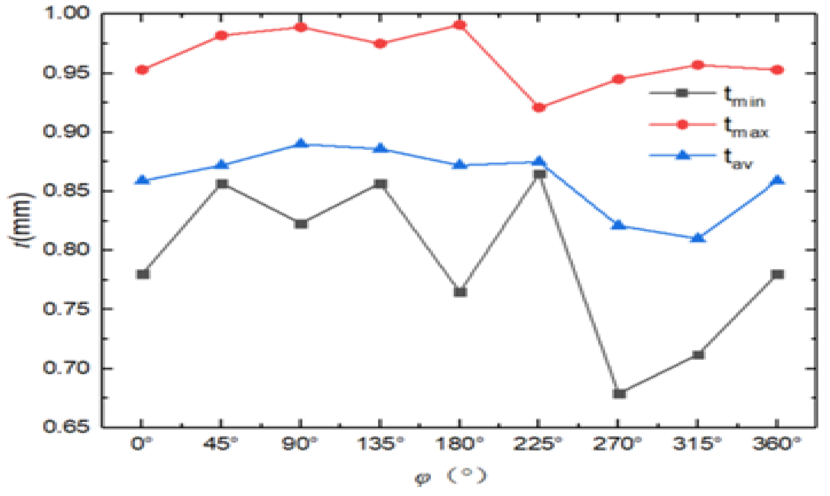
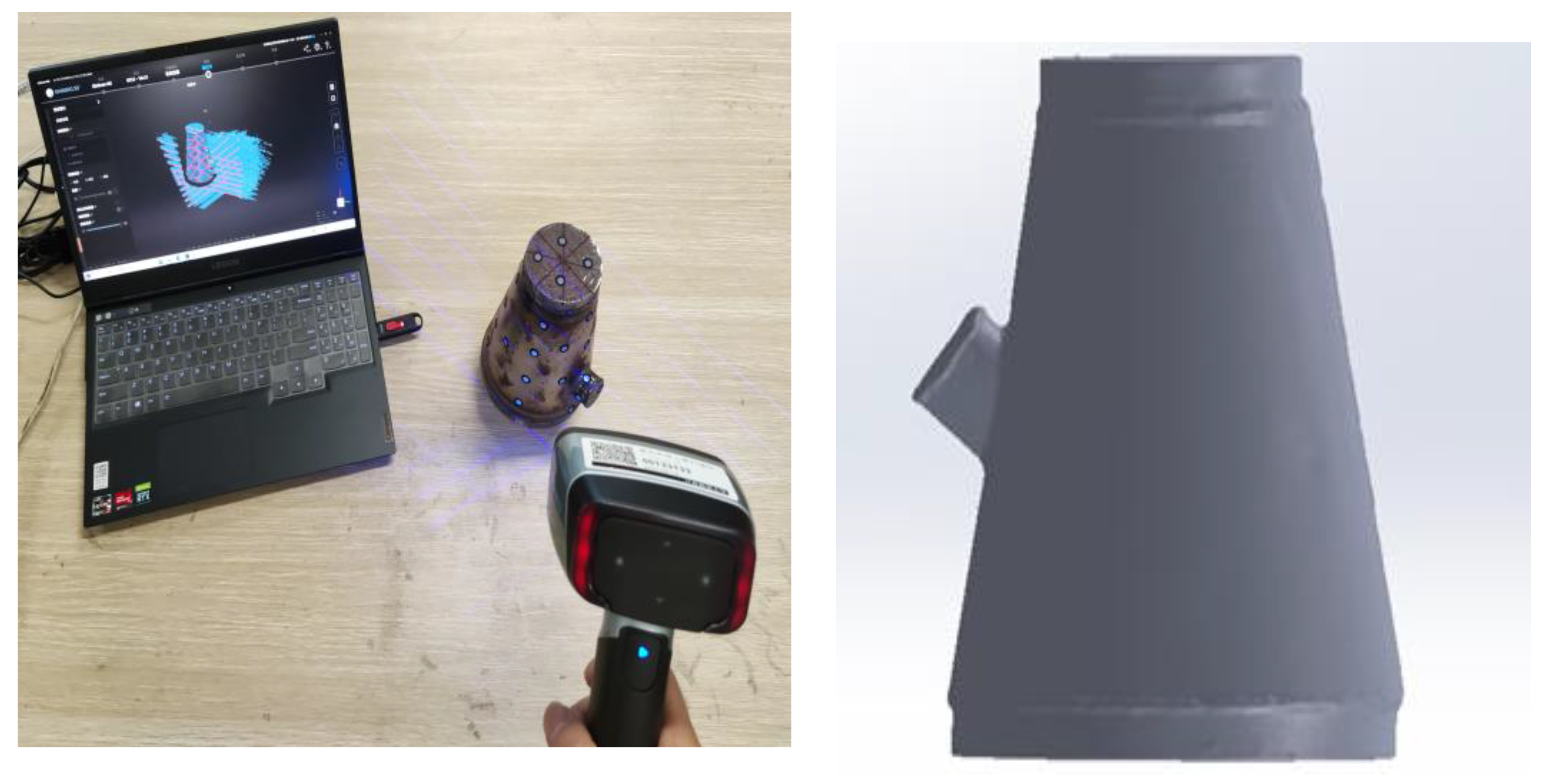
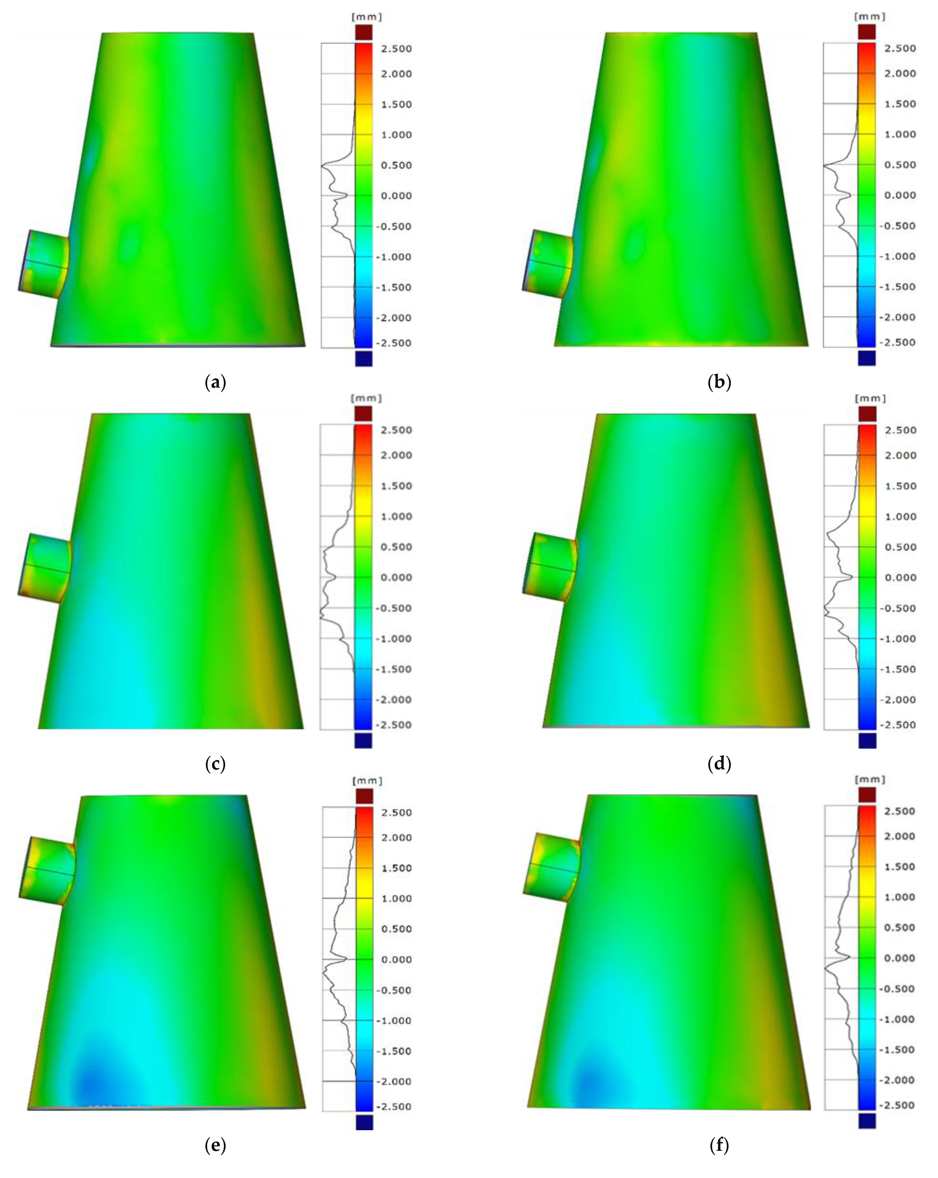
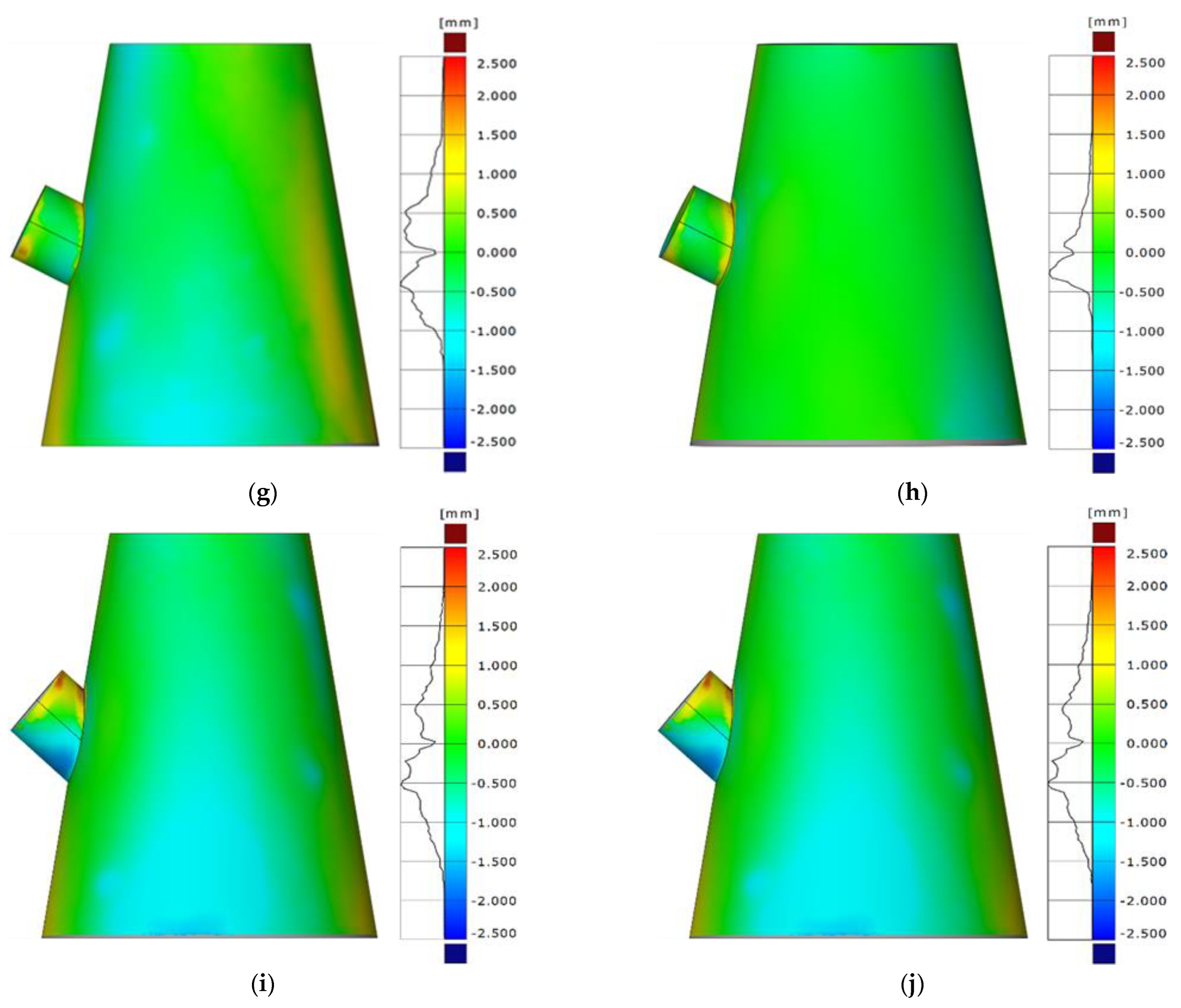
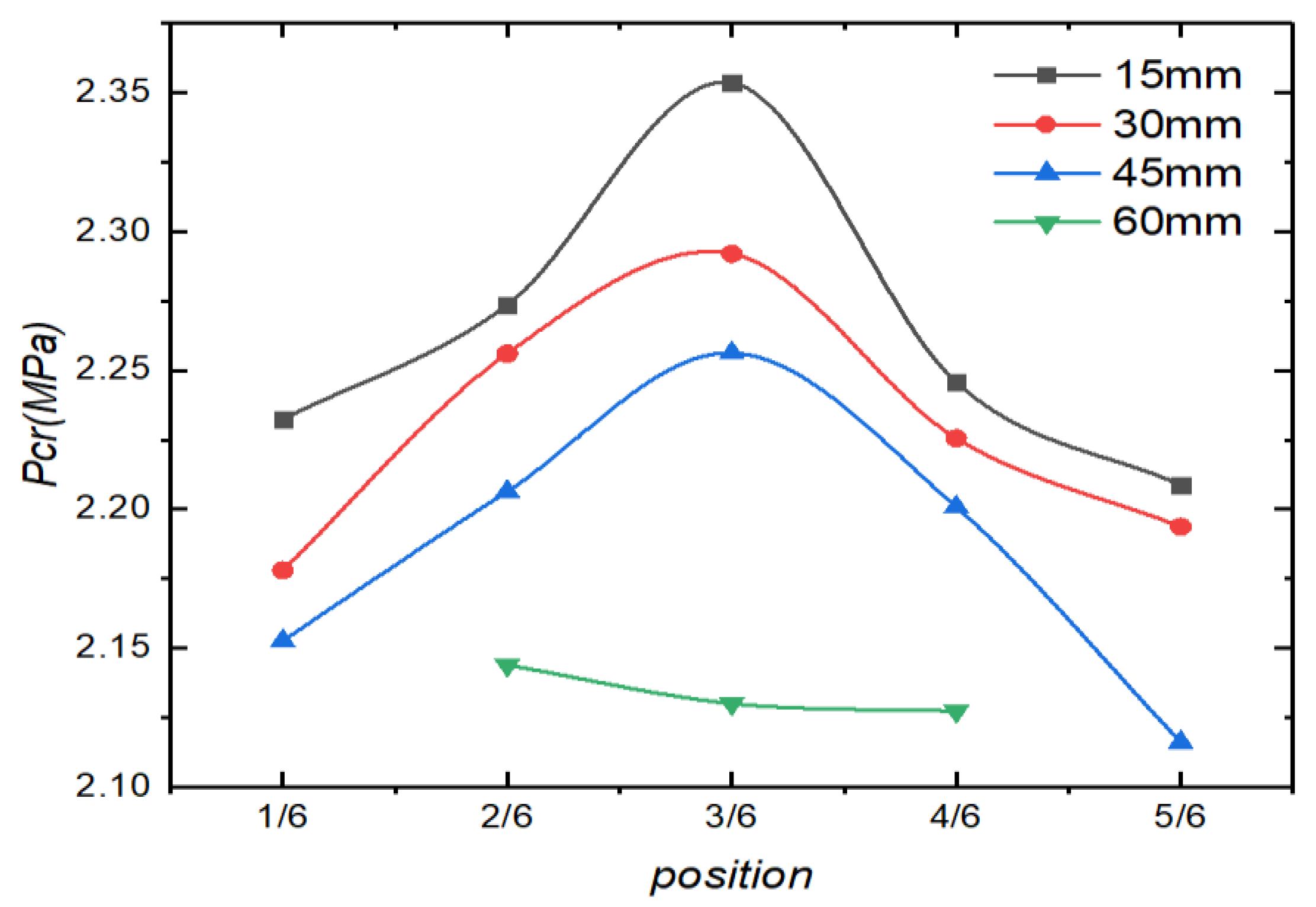
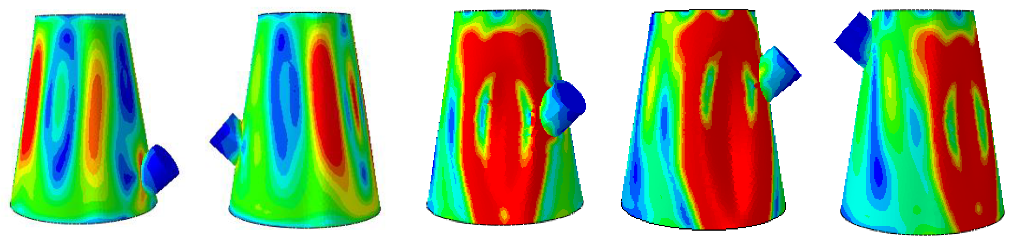
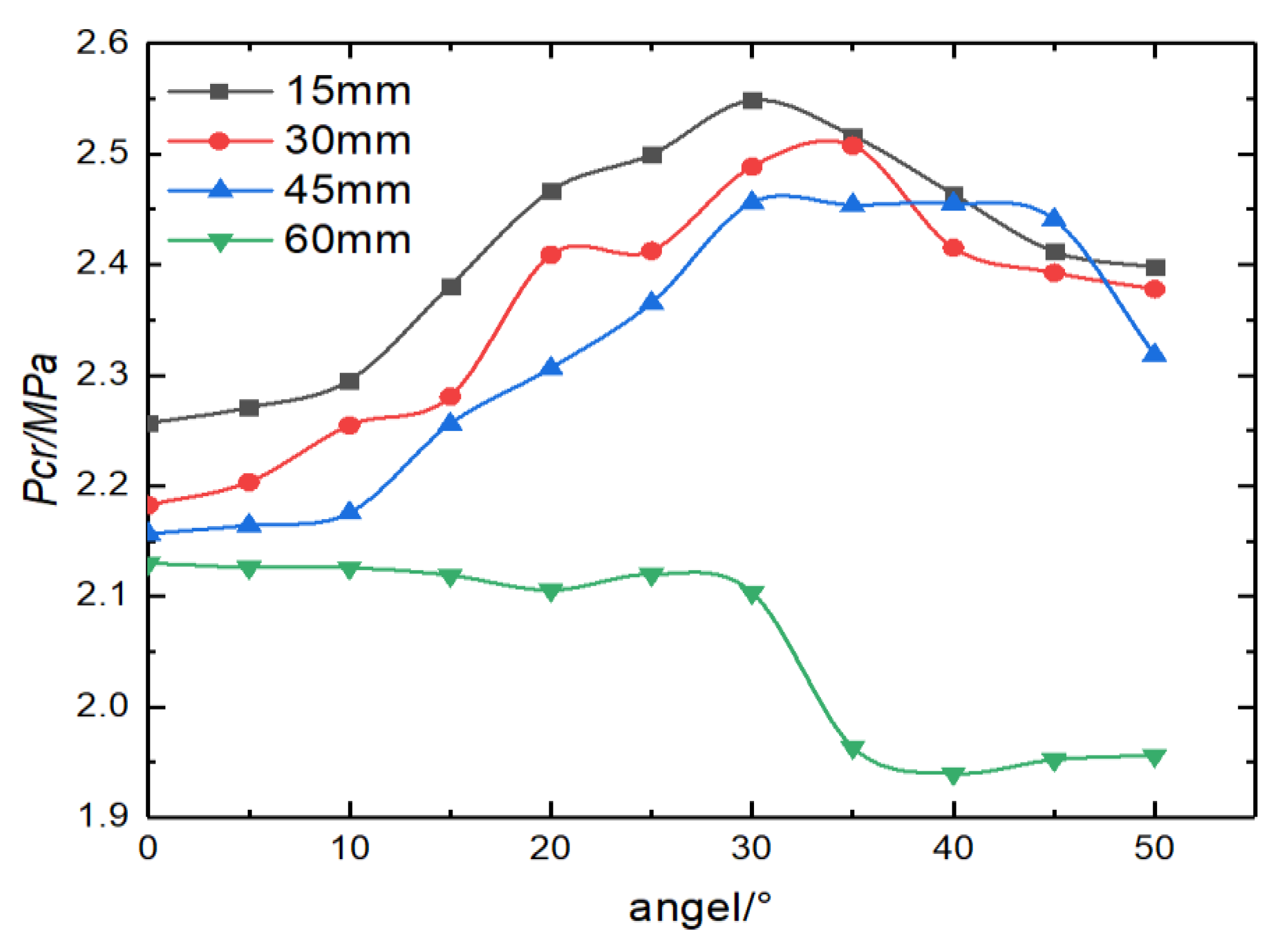
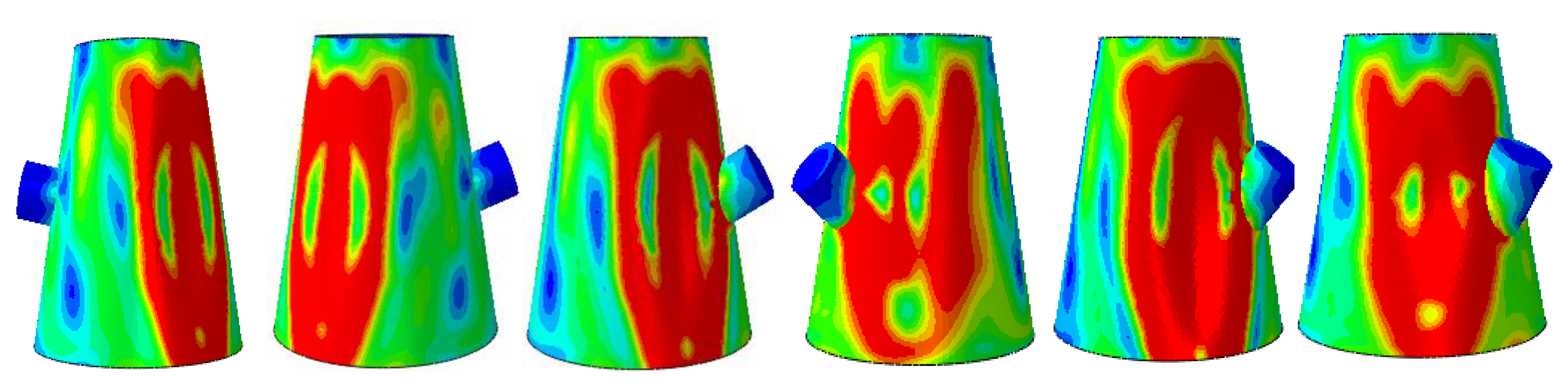
At present, most of the studies focus on small openings and strengthening the wall orthogonal to the openings, and the main research object is the buckling characteristics analysis of complete conical shells and ribbed conical shells, ignoring the influence of the inclined wall on the bearing capacity of the conical shell. At the same time, the influence of large openings and opening positions is also rare. The main focus of this article is on the analysis of the mechanical characteristics of reinforced conical shells with openings, and the impact of the angle of inclination of the reinforced wall on the nonlinear buckling of conical shells is mainly analyzed, which is the main novelty in relation to the current works in the literature on the subject. In this paper, ten stainless steel open-reinforcement conical shells with different opening positions and inclined angles of the wall were fabricated. The thickness test and three-dimensional scanning of the geometric shape were carried out. The buckling performance analysis was carried out using finite element numerical analysis and a hydrostatic pressure experiment. Then, the finite element calculation was carried out in detail based on different inclined angles and opening positions of the reinforcing wall, and its influence on the mechanical properties of the conical shell was analyzed.

2. Materials and Methods

2.1. Conical Shell Opening Reinforcement

In this paper, there are a total of ten stainless steel wall reinforcement conical shells with an opening for the experimental study. The inclination angles of the reinforced wall were selected as 0°, 15° and 30°, and the opening positions are 1/4, 2/4, and 3/4 of the conical shell generatrix, respectively. Each group has two sample models. The basic dimensions of the conical shell are: the diameters of the small end and the large end of the conical shell is   D 1 = 76 mm, D 2 = 128 mm, the wall thickness of the conical shell is t = 1 mm, the length of the conical shell is L = 150 mm, and the opening diameter of the conical shell is d 0 = 30 mm. The reinforced enclosure in this paper is a cylindrical shell enclosure; the thickness of the enclosure is different from the thickness of the conical shell; the whole is cylindrical, penetrated by the opening, and divided into two parts: inner and outer. The parameters of the reinforced wall of the conical shell are the wall thickness   t 0 = 1.2 mm, and the wall height H = 40 mm, respectively. H 1   is the height inside the enclosure; H 2   is the height outside the enclosure; H 1 = H 2   = 20 mm. Table 1 shows the geometric parameters of conical shells with an opening, and Figure 1 shows the schematic diagram of the two conical shells, where α   is the angle between the center line of the reinforced wall and the normal line of the conical shell.

2.2. Geometry and Manufacturing Process

The test models were fabricated according to the above dimensions. Firstly, the 304 stainless steel plate with a nominal thickness of 1 mm was cut and rolled. The two ends of the rolled sample were welded by tungsten inert gas butt welding, and then the hole was opened at the set position. Then, use a 304 stainless steel plate with a nominal thickness of 1.2 mm to roll the welded cylinder as a reinforcing wall. Finally, the large and small ends of the conical shell model and one end of the cylindrical wall were welded to seal. The thickness of the head ( t 1 = 15 mm) was set to 15 times the thickness of the conical shell. The conical shell models were polished after welding. Ten test models are shown in Figure 2.

3. Prediction and Test Data

3.1. Measurement and Geometric Analysis

Firstly, the geometric measurement of the conical shell was carried out, and the measured thickness data provided the parameters for the subsequent finite element simulation. Each conical shell with an opening had 80 measuring points. Eight points were distributed 45° apart along the circumference, and ten points were distributed uniformly along the axis, totaling 80 measurement points, as shown in Figure 3. As shown in Figure 4, the equipment used was an ultrasonic thickness gauge. The working principle was to use the pulse reflection of an ultrasonic wave in the medium to test the thickness of the object, and the measurement accuracy was ±0.001 mm. The thickness gauge probe was coated with an ultrasonic coupling agent before measurement. When the thickness gauge signal reaches full scale or only one full-scale difference, the reading and recording are performed. The measurement results are shown in Table 2, where t 0 was the nominal wall thickness, t m a x was the maximum wall thickness, t m i n   was the minimum wall thickness, t a v e   was the average wall thickness, and t s t d   was the thickness standard deviation. Figure 5 shows the measurement thickness diagram of CS-/2-0-1.
The minimum, maximum, average, and standard deviation data of the wall thickness of the ten conical shell samples are listed in Table 2. The errors of the minimum thickness and the maximum thickness of the ten conical shell models are in the range of 0.148 to 0.340 mm. The average thickness varies in the range from 0.690 to 0.920 mm, and the thickness standard deviation varies in the range from 0.029 to 0.052 mm. These errors may have been caused by the model during the production process. These errors do not affect the rationality of the analysis results, and the analysis results still have reference values.
After measuring the thickness, because there may be pits caused by damage or collision during the processing, these may affect the results of subsequent tests, so it is necessary to perform three-dimensional scanning on the processed conical shell model before the hydraulic test. Before scanning, the model was simply cleaned, and the scanning mark points were attached to the model. The equipment used in this three-dimensional scanning was the handheld three-dimensional scanner of Shining 3D Pro 3D Company, and the scanning accuracy was 0.02 mm. After scanning the model, the redundantly scanned unwanted areas were removed through the splicing of marker points, feature splicing, mixed splicing, and cutting, and finally, the required point cloud data of the entire model surface was obtained. Then, the real geometric contour of the actual model was obtained by the reverse engineering modeling software Geomagic Studio. The scanned model was seamed, the redundant discrete points were removed, and the local coordinate system was attributed to the normal position. Finally, a complete three-dimensional point cloud model was obtained. The scanning process was shown in Figure 6.
After scanning, the head used for sealing does not participate in the actual finite element simulation calculation. Therefore, it is necessary to cut the head with Geomagic Studio software. After cutting the head, it is imported into Gom Inspect for contour surface deviation analysis with the ideal model, and the comparative analysis results are shown in Figure 7. Figure 7 is the contour contrast error cloud diagram of the model. The legend in the figure represents the shape error and error frequency of the real and ideal cylindrical shell models.
From Figure 7, it can be seen that the deviation between the 10 test models and the theoretical model is small in general. The main errors in the ten test models are in the opening reinforcement and the conical shell bus weld, and the remaining surfaces are in good agreement with the theoretical model. Due to the limitations of processing conditions and uncontrollable factors, there is little difference between the experimental model and the theoretical model, but it can still provide a reference for the stability test of conical shell opening reinforcement.

3.2. Experiment

After the measurement and scanning, the hydraulic test was carried out on each specimen. After the test, the water pressure curve of each model was obtained. Considering the buckling load obtained by simulation is small, a pressure chamber with a range of 8 MPa was selected. The preparation steps and procedures for the hydrostatic test were described in detail in previous reports [13,14,15]. The damaged conical shell was shown in Figure 8, in which the CS-3/4-0-2 model fails to leak water and the other models are normal without leakage. Table 3 was the hydrostatic test data table for ten conical shells, and the recorded pressure curve was shown in Figure 9.
From Figure 8, it can be seen that the test models of 10 conical shells all show the failure form of local depression, and the failure positions are similar, being basically distributed near the equator and mostly on the opposite side of the reinforced wall of the conical shell, that is, near the weld (red solid line). It is consistent with the failure mode of a conical shell and a cylindrical shell under external pressure [16,17].
It can be seen from Table 3 that when the reinforced wall is perpendicular to the generatrix (α = 0°), the bearing capacity of the opening position at the 2/4 position is between 10.6% and 21.5% higher than that of the opening position at the 1/4 position and 3/4 position. The bearing capacity of the opening position at 1/4 of the generatrix (near the small end) is 9.9% higher than that of the opening position at 3/4 of the generatrix (near the large end). When the opening position is 2/4 and α = 30°, the ultimate load of the conical shell is the largest, which is 12.1% and 27.1% higher than that of α = 15° and α = 0°.
Figure 9 records the changing trend of the pressure curve of the conical shell during the test under hydrostatic pressure. It can be seen from the curve that the pressurization time is basically within 30 s and that the pressurization trend is slowly rising first and then rapidly increasing until the maximum critical buckling load.

4. Results and Discussion

4.1. Comparison of Experimental and Numerical Analysis

The conical shell model was first built on ABAQUS. The point cloud model scanned in Section 3.1 is imported into ABAQUS to be uniformly thickened. The thickness is the average thickness of the actual measurement of each model. Each model has the same material properties: Young’s modulus E = 200 GPa, Poisson’s ratio μ = 0.291, yield strength σ y = 628 MPa, mass density ρ = 7930 kg / m 3 . Then the model is divided into grids, which are all composed of S4 and S3 grid types. The grid size is determined by the grid density convergence analysis method, and the mesh length cannot exceed 0.5 R t [18]. The same boundary condition setting and loading method are used for each conical shell structure model [19]. One end of the conical shell is fully constrained, and the other end retains axial movement. The outer surface is subjected to P 0 = 1 MPa uniform external pressure load. The boundary conditions and loading are shown in Figure 10.
The nonlinear finite element analysis of the conical shell model is carried out. The risk analysis method is used here. The Riks method is mainly used to solve the material and geometric nonlinear buckling, and the critical buckling load of the conical shell is determined by the LPF curve. In this nonlinear calculation, the real scanning model is used to carry out the finite element method of calculation on the actual model with real defects. In this experiment, the initial arc length is 0.1 mm, the minimum arc length is 0.00001 mm, the maximum arc length is 0.5 mm, and the total arc length iteration step is 100 steps. Figure 11 shows the equilibrium path, critical buckling mode, and post-buckling mode for CS-2/4-30-1. Table 4 shows the numerical results and test results of 10 test models.
It can be seen from Figure 11 that as the deflection increases, the applied pressure increases monotonically at first, but after reaching its peak, the pressure decreases greatly. The failure mode of the opening reinforced conical shell is local depression, which is basically consistent with the collapse mode of the corresponding test model, indicating that the hydrostatic test results are in good agreement with the numerical analysis results.
According to Table 4, it can be seen that among the 10 conical shells, except that the failed CS-0-3/4-2 is not included, the maximum difference between the numerical results and the test results is 17.8%, and the minimum difference is 1.80%. This difference may be attributed to the 304 stainless steel material’s properties of having small differences. The results show that the nonlinear critical buckling load of the conical shell with an opening can be obtained based on the actual geometric shape, the average thickness, and material properties.

4.2. The Effect of Opening Position on Critical Buckling Load under Different Apertures

This section mainly discusses the effect of opening position and opening size on the stability of conical shells. The reinforced wall is set perpendicular to the generatrix of the conical shell, the opening position is selected from 1/6 to 5/6, each at a 1/6 interval, and the opening sizes are 15, 30, 45, and 60 mm, respectively. A total of 20 models were established. According to the finite element analysis method described in Section 4.1, the characteristic defect of the first-order mode is introduced into the nonlinear buckling analysis in this section as the initial geometric defect of the conical shell. The geometric defect factor is 10~60% of the shell thickness, and 20% of the shell thickness is selected in this paper. The analysis results are shown in Table 5. At 1/6 and 5/6, the opening with a diameter of 60 mm exceeds the conical shell, so this situation does not participate in the data analysis and discussion.   ρ is the ratio of the aperture d 0 to the diameter of the cone where the hole center is located. The critical buckling loads of four apertures at different opening positions. The critical buckling load curves of the four apertures at different opening positions are shown in Figure 12.
Figure 12 shows that when the opening position is the same, the bearing capacity of the conical shell decreases with the increase in the opening diameter. When the opening rate is less than 0.540, the closer the opening position is to the middle, the greater the critical buckling load is, and the load is the largest when the opening is in the middle position. When the opening ratio reaches 0.540, the opening position has little effect on the bearing capacity of a conical shell.
Taking the aperture of 30 mm as an example, the following is a set of buckling mode diagrams of reinforced conical shells with openings at positions 1/6, 2/6, 3/6, 4/6, and 5/6, respectively, when the aperture is 30 mm. As shown in Figure 13.
From Figure 13, it can be seen that the larger stress areas of the five modes are distributed in a block shape. When the opening positions are 3/6 or 4/6, the collapse area mainly surrounds the area near the reinforced enclosure wall. When the opening positions are 1/6, 2/6, and 5/6, the collapse area is all near the opposite side of the reinforced enclosure wall. The position of the opening has a certain impact on the buckling mechanical characteristics of the conical shell strengthened by the opening.

4.3. The Effect of Inclination Angle on Critical Buckling Load under Different Apertures

This section mainly discusses the effect of the inclination angle and opening size on the stability of a conical shell. The opening position is set at 1/2 of the generatrix of the conical shell, the inclination angle of the reinforced wall is selected in the range from 0 to 50°, with an interval of 5°, and the opening sizes are 15, 30, 45, and 60 mm, respectively. A total of 44 models are established to discuss the effect of the inclination angle of the wall and the opening size on the critical load of the conical shell. The analysis results are shown in Table 6. The curves of the critical buckling load values of the four apertures at different wall inclination angles are shown in Figure 14.
As can be seen from Table 5 and Figure 14, when the inclined angle of the wall is invariant, the critical load of the conical shell decreases with the increase in the opening diameter. When the opening ratio is less than 0.441, the load of the conical shell increases with the increase in the inclination angle of the wall. When the inclination angle increases to about 30°, the load reaches its maximum value, then gradually decreases and stops at about 45°. However, when the opening ratio reaches 0.588, the critical buckling load of the conical shell reaches its maximum when the inclination angle of the wall is 0°, then it basically shows a straight line, decreases linearly at about 30°, and then tends to be gentle. This finding indicates that small openings, such as some installation equipment or pipelines, can be selected when the wall inclination angle is about 30°. This is basically consistent with the influence of the inclination angle of the wall on the ultimate load of the pipeline in Reference [20]. When opening large holes such as manholes or observation windows, it is more inclined to open vertically.
Taking the aperture of 30 mm as an example, the following is a set of buckling mode diagrams of reinforced conical shells with holes around the angle of the reinforced wall. They are 0°, 10°, 20°, 30°, 40°, and 50° from left to right, as shown in the following Figure 15.
From Figure 15, it can be seen that the larger stress areas of the six modes are all distributed in a sheet-like manner. When the inclination angle of the reinforcement wall with holes is between 0° and 10°, the collapse area mainly surrounds the sheet-like area opposite the reinforcement wall. When the inclination angle of the reinforcement wall with holes is 20°, 30°, 40°, or 50°, the collapse area mainly surrounds the sheet-like area opposite the reinforcement wall, indicating that as the inclination angle of the wall increases, the stress around the wall is also more pronounced.

5. Conclusions

In this paper, the effects of opening parameters and reinforcing wall parameters on the bearing capacity of a conical shell are studied. The numerical results and the test results of the actual model are compared. The conclusions are as follows:
(1) The difference between the numerical results and the experimental results of 10 conical shells with an opening is within 17.8%. Based on the real geometry, average thickness, and material properties, the nonlinear critical load of the conical shell with an opening can be obtained. The final failure mode obtained by the numerical analysis is consistent with the collapse mode obtained by the hydraulic test of the actual model. The collapsed position of the hydraulic test is the opposite of the opening reinforcement position, indicating the effectiveness of the wall reinforcement on the bearing capacity of the conical shell.
(2) With the increase in opening diameter, the bearing capacity of conical shells shows a decreasing trend. When the opening reinforcement wall is perpendicular to the generatrix of the conical shell and the opening ratio is less than 0.540, the critical buckling load is maximum when the opening is in the middle position. When the opening ratio reaches 0.540, the opening position has little effect on the bearing capacity of a conical shell.
(3) When the opening ratio is less than 0.441, the inclination angle of the wall is about 30°, and the critical buckling load reaches its maximum. Therefore, when some small openings are needed, such as for installation equipment or pipelines, an inclination angle of the wall of around 30° can be selected. When the opening rate reaches 0.588, it shows that the critical buckling load of the conical shell with an opening reaches its maximum when the inclination angle of the wall is 0°. Therefore, when large openings such as manholes or observation windows are opened, they are more inclined to open vertically.

Author Contributions

Conceptualization, methodology and funding acquisition, Y.Z.; Software, validation, formal analysis, writing—original draft preparation, writing—review and editing, L.Y.; Ivestigation and resources, H.P.; Visualization and project administration, T.S.; Supervision and project administration, J.Z. All authors have read and agreed to the published version of the manuscript.

Funding

This work was supported by the National Natural Science Foundation of China [grant numbers: 52271277], the Natural Science Foundation of Jiangsu Province [grant no. BK20211343], and the State Key Laboratory of Ocean Engineering at Shanghai Jiao Tong University [grant no. GKZD010081].

Informed Consent Statement

Informed consent was obtained from all subjects involved in the study.

Data Availability Statement

In this section, please provide details regarding where data supporting reported results can be found, including links to publicly archived datasets analyzed or generated during the study.

Conflicts of Interest

The authors declare no conflict of interest.

References

  1. Shan, L.; Weibo, W. Research status and prospect of pressure hull structure of submersible. Ship Sci. Technol. 2019, 41, 7–16. [Google Scholar]
  2. Shiping, S.; Jiantang, H.; Weihong, Z. Optimization of opening shape of revolution shell based on hyperelliptic equation and sequential response surface method. Acta Aeronaut. Sin. 2015, 36, 3595–3607. [Google Scholar]
  3. Teng, J.G.; Zhao, Y.; Lam, L. Techniques for buckling experiments on steel silo transition junction. Thin Walled Struct. 2015, 39, 685–707. [Google Scholar] [CrossRef]
  4. Ross, C.T.F.; Little, A.P.F.; Adeniyi, K.A. Plastic buckling of ring-stiffened conical shells under external hydrostatic pressure. Ocean Eng. 2005, 32, 21–36. [Google Scholar] [CrossRef]
  5. Wintersetter, T.A.; Schmit, H. Stability of circular cylindrical steel shells under combined loading. Thin Walled Struct. 2001, 40, 893–909. [Google Scholar] [CrossRef]
  6. Popov, A.A. Parametric resonance in cylindrical shells: A case study in nonlinear vibration of structural shell. Eng. Struct. 2003, 25, 789–799. [Google Scholar] [CrossRef]
  7. Golzan, B.S.; Showkati, H. Buckling of thin-walled conical shells under uniform external pressure. Thin Walled Struct. 2008, 46, 516–529. [Google Scholar] [CrossRef]
  8. Cho, S.-R.; Muttaqie, T.; Do, Q.T.; Park, S.H.; Kim, S.M.; So, H.Y.; Sohn, J.M. Experimental study on ultimate strength of steel-welded ring-stiffened conical shell under external hydrostatic pressure. Mar. Struct. 2019, 67, 102634. [Google Scholar] [CrossRef]
  9. Chunfang, W. Analysis of stress characteristics of openings in ring-stiffened conical shells. Electromech. Inf. 2011, 12, 203–204. [Google Scholar]
  10. Kathiresan, M. Influence of shape, size and location of cutouts on crashworthiness performance of aluminum conical frusta under quasi-static axial compression. Thin Walled Struct. 2020, 154, 106793. [Google Scholar] [CrossRef]
  11. Debski, H.; Rozylo, P. Experimental study on the effect of eccentric compressive load on the stability and load-carrying capacity of thin-walled composite profiles. Compos. Part B 2021, 226, 109346. [Google Scholar] [CrossRef]
  12. Rozylo, P.; Wysmulski, P. Failure analysis of thin-walled composite profiles subjected to axial compression using progressive failure analysis (PFA) and cohesive zone model (CZM). Compos. Struct. 2021, 262, 113597. [Google Scholar] [CrossRef]
  13. Ma, Q. Opening Reinforcement Design and Experimental Investigation of Spherical Shell for Deep-Sea Submersible; Jiangsu University of Science and Technology: Zhenjiang, China, 2018. [Google Scholar]
  14. Zhu, Y.; Chen, B.; Zhao, B.; Zhao, X.; Tang, W.; Wang, X. Buckling characteristics of externally pressurised toroidal shell. Ships Offshore Struct. 2020, 15, 804–814. [Google Scholar] [CrossRef]
  15. Zhu, Y.M.; Zhang, Y.W.; Zhao, X.L.; Zhang, J.; Xu, X. Elastic-plastic buckling of externally pressurized hemispherical heads. Ships Offshore Struct. 2019, 14, 829–838. [Google Scholar] [CrossRef]
  16. Jasion, P.; Magnucki, K. Elastic buckling of clothoidal-spherical shells under external pressure—Theoretical study. Thin Walled Struct. 2015, 86, 18–23. [Google Scholar] [CrossRef]
  17. Zhang, J.; Wang, M.L.; Wang, W.B.; Tang, W.; Zhu, Y. Investigation on egg-shaped pressure shells. Mar. Struct. 2017, 52, 50–66. [Google Scholar] [CrossRef]
  18. Ifayefunmi, O.; Błachut, J. The effect of shape, boundary and thickness imperfections on plastic buckling of cones. In Proceedings of the International Conference on Ocean, Offshore and Arctic Engineering, Rotterdam, the Netherlands, 19–24 June 2011; Volume 2, pp. 23–33. [Google Scholar]
  19. Zhu, Y.; Yu, J. Effects of the geometrical shapes on buckling of conical shells under external pressure. Int. J. Press. Vessel. Pip. 2022, 196, 104624. [Google Scholar] [CrossRef]
  20. Li, N. Study on plastic limit load of internal pressure inclined nozzle structure. Mech. Strength 2007, 29, 970–974. [Google Scholar]
Figure 1. The structure of the conical shell with an opening: (a) the conical shell with 1/4 position and an angle of 0°; (b) the conical shell with 2/4 position and an angle of 30°.
Metals 13 00824 g001
Figure 2. The test models. (a) CS-1/4-0-1, (b) CS-1/4-0-2, (c) CS-2/4-0-1, (d) CS-2/4-0-2, (e) CS-3/4-0-1, (f) CS-3/4-0-2, (g) CS-2/4-15-1, (h) CS-2/4-15-2, (i) CS-2/4-30-1, (j) CS-2/4-30-2.
Metals 13 00824 g002
Figure 3. Distribution of the wall thickness measurement points of the test.
Metals 13 00824 g003
Figure 4. Sample model actual thickness measurement.
Metals 13 00824 g004
Figure 5. Thickness distribution diagram of CS-/2-0-1.
Metals 13 00824 g005
Figure 6. Three-dimensional scanning.
Metals 13 00824 g006
Figure 7. Fabrication deviations of the test models from perfect geometries. (a) CS-1/4-0-1, (b) CS-1/4-0-2, (c) CS-2/4-0-1, (d) CS-2/4-0-2, (e) CS-3/4-0-1, (f) CS-3/4-0-2, (g) CS-2/4-15-1, (h) CS-2/4-15-2, (i) CS-2/4-30-1, (j) CS-2/4-30-2.
Metals 13 00824 g007aMetals 13 00824 g007b
Figure 8. Conical shells with an opening after failure. (a) CS-1/4-0-1, (b) CS-1/4-0-2, (c) CS-2/4-0-1, (d) CS-2/4-0-2, (e) CS-3/4-0-1, (f) CS-3/4-0-2, (g) CS-2/4-15-1, (h) CS-2/4-15-2, (i) CS-2/4-30-1, (j) CS-2/4-30-2.
Metals 13 00824 g008
Figure 9. Hydrostatic pressure curves for the shell samples.
Metals 13 00824 g009
Figure 10. Mesh and boundary constraint modes of the numerical model: (a) the conical shell with 1/4 position and an angle of 0°; and (b) the conical shell with 2/4 position and an angle of 30°.
Metals 13 00824 g010
Figure 11. Equilibrium path, critical buckling mode, and post-buckling mode for CS-2/4-30-1: Pcr/P0 is the ratio of the applied external load to the initial load (P0 = 1 MPa), and Umax/t is the ratio of the maximum deformation Umax to the nominal shell thickness t.
Metals 13 00824 g011
Figure 12. Opening position-critical buckling load curve.
Metals 13 00824 g012
Figure 13. Nonlinear buckling mode of position-critical buckling load.
Metals 13 00824 g013
Figure 14. Wall inclination angle-critical buckling load curve.
Metals 13 00824 g014
Figure 15. Nonlinear buckling mode of angle-critical buckling load.
Metals 13 00824 g015
Table 1. The geometric parameters of conical shells with an opening.
Sample d 0   H 1 H 2 α Opening Position
(mm)(mm)(mm)(mm)
CS-1/4-030202001/4
CS-2/4-030202002/4
CS-3/4-030202003/4
CS-2/4-15302020152/4
CS-2/4-30302020302/4
Table 2. Measurement results of the ten test models.
Sample t m i n t a v t m a x t s t d
(mm)
CS-1/4-0-10.6840.8040.9240.052
CS-1/4-0-20.6970.8250.9520.046
CS-2/4-0-10.6570.7790.9010.032
CS-2/4-0-20.7820.8530.9230.029
CS-3/4-0-10.6200.6900.7600.038
CS-3/4-0-20.6470.7290.8100.035
CS-2/4-15-10.6350.9200.7790.040
CS-2/4-15-20.6840.7630.8410.047
CS-2/4-30-10.6970.7450.7930.041
CS-2/4-30-20.6120.6980.7830.037
Table 3. Test results of ten conical shells.
Sample P 1 t e s t   ( MPa ) P 2 t e s t   ( MPa ) P t e s t a v e   ( MPa )
CS-1/4-01.6241.7641.694
CS-2/4-01.7921.9531.873
CS-3/4-01.542-1.542
CS-2/4-152.0342.2132.124
CS-2/4-302.3262.4352.381
Table 4. Numerical analysis results.
Name P A B A Q U S   ( MPa ) P t e s t   ( MPa ) P A B A Q U S / P t e s t
CS-2/4-0-11.8451.7021.084
CS-2/4-0-21.8571.9530.951
CS-1/4-0-11.7151.6241.056
CS-1/4-0-21.7321.7640.982
CS-3/4-0-11.7801.5421.154
CS-2/4-15-12.3962.0341.178
CS-2/4-15-22.4132.2131.090
CS-2/4-30-12.4122.3261.037
CS-2/4-30-22.3842.4350.979
Table 5. The critical buckling load of a conical shell with an opening under different opening positions.
Open PositionModel d 0   ( mm ) ρ P c r   ( MPa )
1/61150.1772.232
2300.3542.178
3450.5312.153
4600.708-
2/65150.1602.274
6300.3202.256
7450.4812.206
8600.6412.144
3/69150.1472.354
10300.2942.292
11450.4412.2564
12600.5882.130
4/613150.1352.246
14300.2702.225
15450.4052.201
16600.5402.127
5/617150.1252.209
18300.2502.194
19450.3752.116
20600.500-
Table 6. Critical loads of conical shells with an opening at different inclination angles and opening sizes.
α (°) Model d 0   ( mm ) ρ P c r   ( MPa ) α (°) Model d 0   ( mm ) ρ P c r   ( MPa )
01150.1472.2573025150.1472.548
2300.2942.18226300.2942.488
3450.4412.15627450.4412.456
4600.5882.13028600.5882.103
55150.1472.2713529150.1472.516
6300.2942.20330300.2942.508
7450.4412.16431450.4412.454
8600.5882.12632600.5881.964
109150.1472.2954033150.1472.464
10300.2942.25534300.2942.415
11450.4412.17535450.4412.455
12600.5882.12636600.5881.940
1513150.1472.3814537150.1472.412
14300.2942.28138300.2942.393
15450.4412.25639450.4412.441
16600.5882.11940600.5881.952
2017150.1472.4675041150.1472.397
18300.2942.40942300.2942.378
19450.4412.30643450.4412.318
20600.5882.10544600.5881.956
2521150.1472.499
22300.2942.412
23450.4412.365
24600.5882.120
Disclaimer/Publisher’s Note: The statements, opinions and data contained in all publications are solely those of the individual author(s) and contributor(s) and not of MDPI and/or the editor(s). MDPI and/or the editor(s) disclaim responsibility for any injury to people or property resulting from any ideas, methods, instructions or products referred to in the content.

