1. Introduction
Cu has been widely used in the fields of electronics, functional materials, automobiles and machinery manufacturing because of its highly electrical nature, excellent conductivity, thermal conductivity and low cost (compared with Ag and Au) [
1,
2]. Recently, with the development of technology, the related industries have put forward higher requirements for the performance of copper. However, due to its poor strength, low hardness and wear resistance, the application of Cu in the industrial field is limited [
3,
4,
5,
6]. Developing novel Cu composites simultaneously characterized by excellent mechanical, tribological and corrosion properties has been the relevant challenge in materials science. In order to solve this problem, the main methods generally include macro- and micro-doping of alloys and the formation of special types of the structure (duplex, ultrafine, nanocrystalline, etc.), of which the reinforcement of Cu alloys by hard phases is widely used [
7,
8,
9].
Table 1 shows the mechanical properties of Cu based composites with different reinforcements. It has been found that ceramic particles with excellent mechanical properties are usually introduced into the copper matrix as reinforcement phases, and copper can give full play to excellent comprehensive properties by regulating the type, content and distribution of the reinforcement phases [
10,
11,
12]. However, due to poor wettability, it is generally difficult for ceramic particles to be effectively introduced into Cu melt [
13,
14,
15]. For the time being, many methods have been developed for preparing the composite materials, and as a commonly used method, the reinforcement of composite materials can be in situ synthesized in copper melt by the melt reaction method so as to realize the effective combination of the reinforcement and matrix interface and improve the properties of composite materials [
16,
17,
18,
19].
In Cu alloys, a large number of transition metal silicides tend to grow into rods with a certain aspect ratio, and the transition metal carbides are mostly granular. When both are used as reinforcers in the Cu matrix, they will work well together [
19,
20]. In our previous studies, it was found that Ti
5Si
3 will assist the introduction of TiC into Cu melts and promote its dispersion so that the TiC–Ti
5Si
3-reinforced Cu matrix composites have better distribution and organization than single TiC-reinforced composites [
21,
22,
23]. It can be deduced that, compared to the composites reinforced by either TiC or Ti
5Si
3, the formation of a TiC–Ti
5Si
3 hybrid system is more helpful for improving the properties of the composites due to the different reinforcement morphologies of TiC and Ti
5Si
3.
At present, for the preparation of the TiC–Ti
5Si
3-reinforced Cu matrix composites, compared to the easy formation of Ti
5Si
3 by introducing Si and Ti elements into Cu melts, it is very difficult to add or synthesize TiC because of the poor wettability between the Cu melts and both TiC and other carbon-containing sources, such as graphite, which can react with Ti to form the TiC. As a consequence, the key aspect for preparing the TiC–Ti
5Si
3 hybrid-reinforced Cu matrix composites is how to introduce or synthesize TiC in the Cu matrix effectively. According to our previous works [
21], it is also discovered that the reactive wetting based on the Ti–C reaction is a very effective way to prepare TiC-reinforced Cu matrix composites. Interestingly, when the carbon source is SiC in the Ti–C reaction system, besides the synthesis of TiC, Ti
5Si
3 can also be simultaneously formed. As a result, TiC–Ti
5Si
3 hybrid-reinforced Cu matrix composites can be prepared based on this.
It has been reported in our previous works [
23,
24] that the possible Ti–SiC reaction should be the following reaction (1). However, according to the formation of graphite derived from SiC during the reaction between Ti and SiC with a larger size, it has been suggested that there are two stages for the reaction (1): the first stage is forming Ti
5Si
3 and C; (2) the second stage is forming TiC. The reaction processes are expressed by reactions (2) and (3). According to the results, the simultaneous synthesis of TiC and Ti
5Si
3 by the addition of the Ti–SiC mixture into Cu melts is chosen as the method for preparing the TiC–Ti
5Si
3 hybrid-reinforced Cu matrix composites in this work.
The Gibbs free energies for the above three reactions at 1273 K were calculated, which were about −909 kJ/mol, −400 kJ/mol and −170 kJ/mol, respectively. The calculated results prove that the reactions are thermally favorable.
Therefore, in this paper, in order to further investigate TiC–Ti5Si3-reinforced Cu matrix composites, based on the melt reaction method combined with the traditional casting process, Cu matrix composites with different contents of TiC–Ti5Si3 hybrid-reinforced phases were prepared, the microstructures of the prepared composites were analyzed and the hardness of the composites was also tested.
3. Results and Discussion
In this study, three kinds of prepared composites, with compositions of Cu-4.86Ti-1Si-0.43C, Cu-6.8Ti-1.4Si-0.6C and Cu-9.72Ti-2Si-0.86C, were prepared, which correspond to Cu-4.86Ti-1.43SiC, Cu-6.8Ti-2SiC and Cu-9.72Ti-2.86SiC, respectively, before the Ti–SiC reaction. In theory, when SiC absolutely reacts with Ti to form TiC and Ti
5Si
3, the mass ratio of SiC and Ti should be 3.2:1. Because the wettability between the TiC and Cu melts was very poor, a little more Ti has an advantage in the formation and dispersion of TiC. Therefore, the more accurate composition of the composites after the reaction of Ti–SiC to form TiC and Ti
5Si
3 would be Cu—3.7 vol.%, TiC—7.5 vol.%, Ti
5Si
3 and Cu—5.1 vol.%, TiC—10.3 vol.%, Ti
5Si
3 and Cu—7 vol.%, TiC—14.2 vol.% and Ti
5Si
3, respectively. According to our previous research [
23], the Ti–SiC mixture will be immediately reacted after the addition into Cu melts, and the reaction products will be rapidly dispersed in the melts. The microstructures of the obtained as-cast composites are shown in
Figure 1.
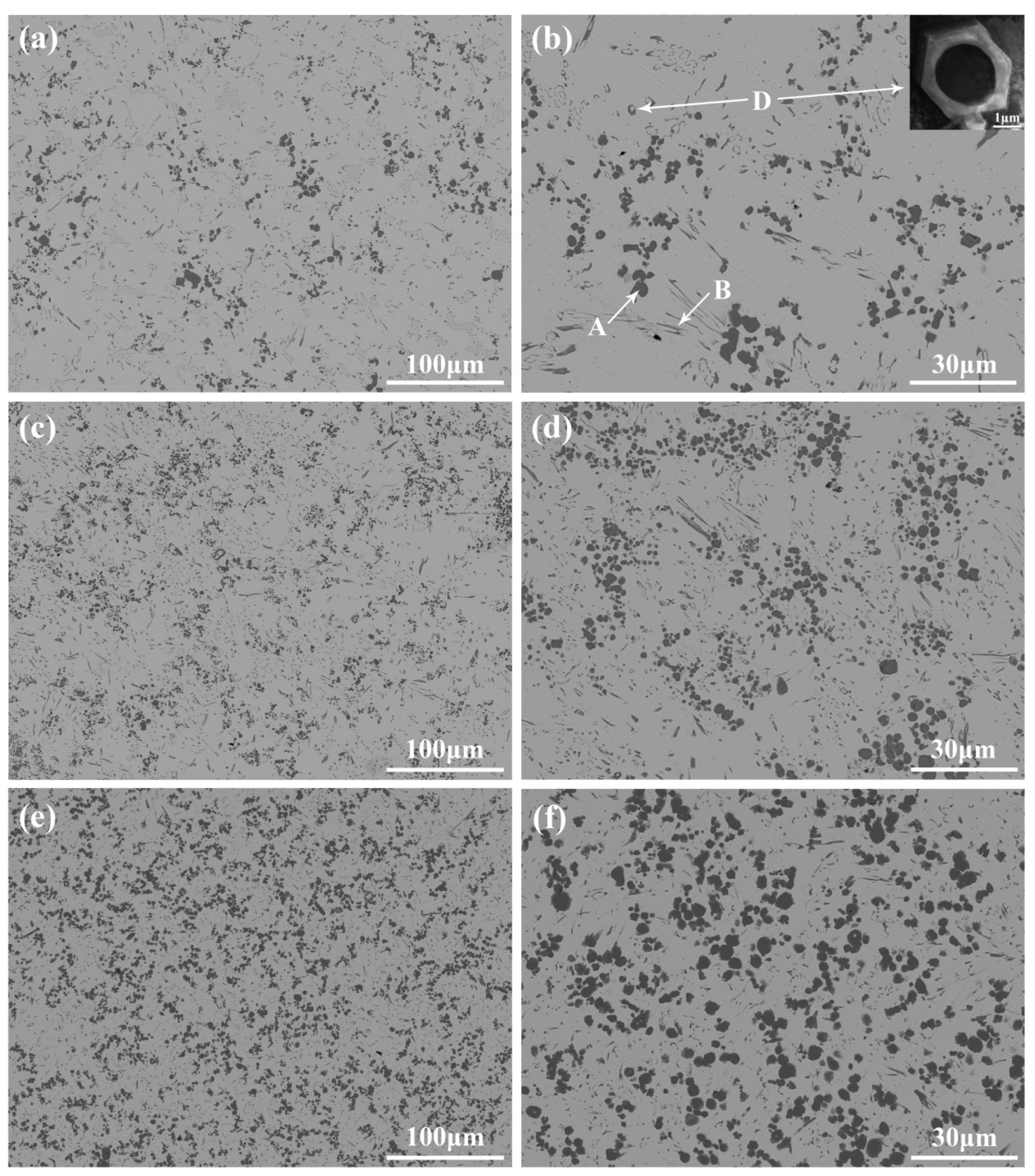
The microstructures of the TiC–Ti
5Si
3-reinforced Cu composites prepared by the melt reaction method combined with the traditional casting process are shown in
Figure 1. It can be seen in
Figure 1a,b that there seem to be three phases with different morphologies in the Cu matrix in the prepared Cu-4.86Ti-1Si-0.43C composite. The first one, which is marked as A in
Figure 1b, is granular, with a size ranging from 1 μm to 6 μm, and the average mean is about 2 μm.
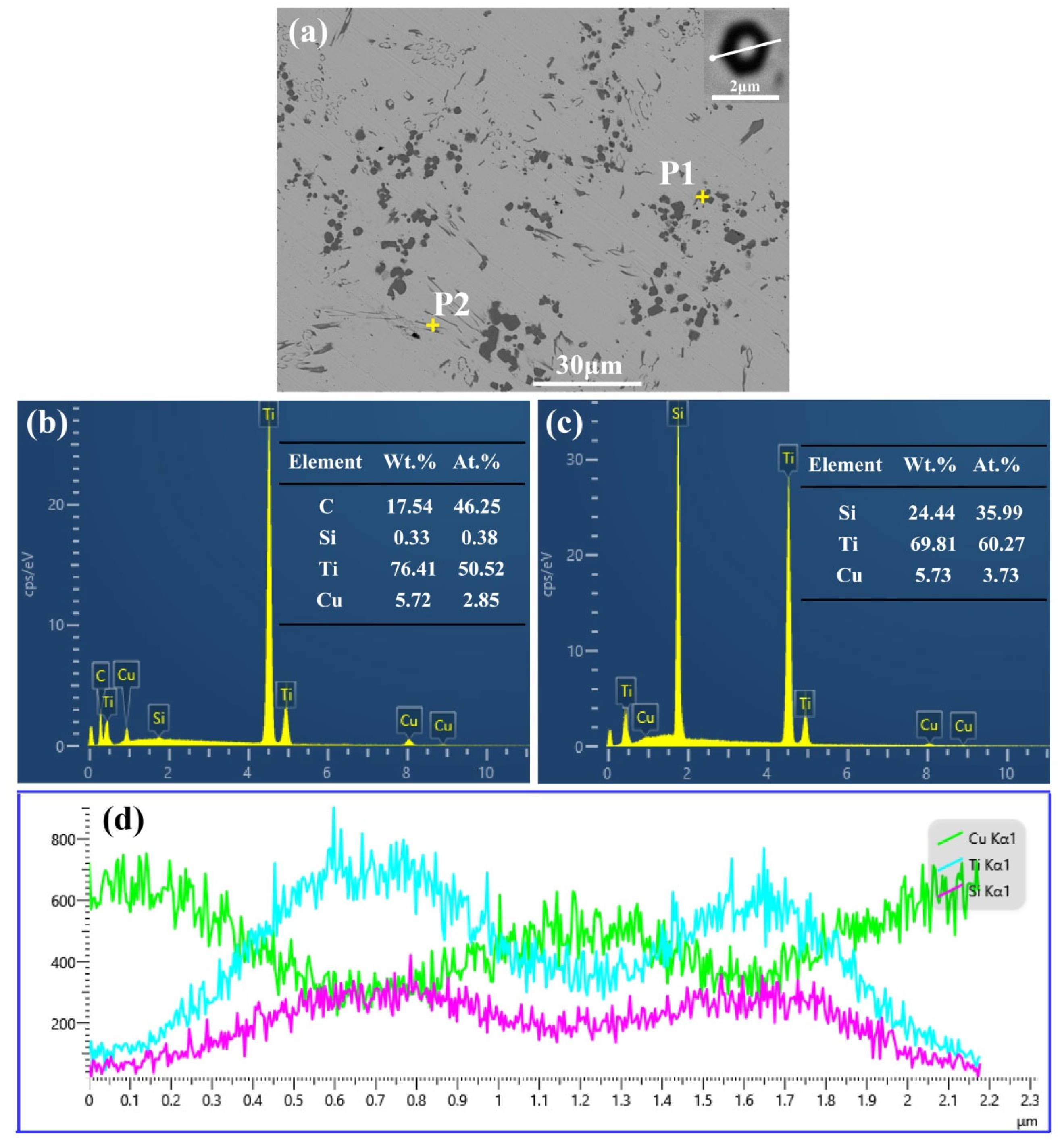
Figure 2 shows the EDS analysis of the synthesized TiC and Ti
5Si
3 in the Cu-4.86Ti-1Si-0.43C sample. It can be seen in
Figure 2b that the particles primarily include C and Ti elements, and the Ti/C atomic ratio is near 1:1. This result indicates that these particles are synthesized TiC particles. The second phase, marked as B in
Figure 1b, which is acicular or claviform, mainly contains Ti and Si elements, as shown in
Figure 2c. The atomic ratio of Ti and Si is about 1.67, demonstrating that it is the Ti
5Si
3 phase. The third phase, marked as D in
Figure 1b, also seems to be granular, with an approximate size of 1~2 μm. However, it is noticed that, unlike the TiC particles, most of the D phase is not single-phase but consists of two phases. The magnified microstructure inserted in
Figure 1b further confirmed that the D is a kind of the core–shell phase, with a thickness of the core ranging from about 100 nm to 500 nm. It is also found that the shell of the D phase is hexagonal, while the core is circular.
Figure 2d shows the EDS line analysis results, which further prove that the shell of the D phase primarily includes Si and Ti, and the core is primarily Cu. Thus, it can be further proved that the D phase is the Cu@TixSiy phase, which has a core–shell structure.
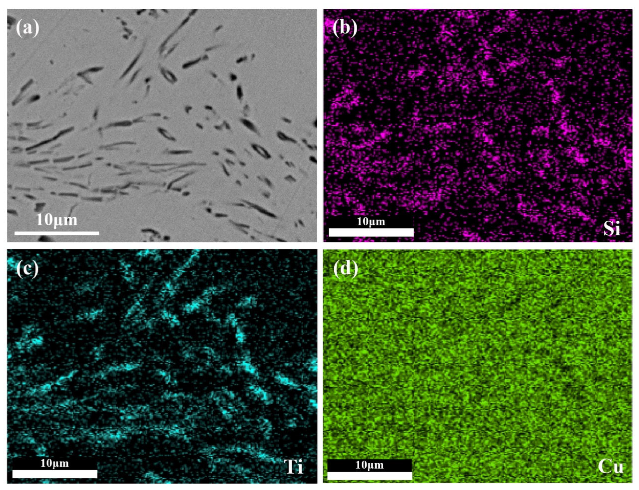
Figure 3 displays the EDS mapping analysis results of the Ti
5Si
3 in prepared as-cast composites. The result of EDS mapping analysis further confirmed the above conclusion. It can be more clearly seen that the rod-like B phase and the shell of the D phase mainly consist of Ti and Si, while the core of the D phase is composed of the Cu element. The phase compositions of the prepared Cu-6.8Ti-1.4Si-0.6C and Cu-9.72Ti-2Si-0.86C composites are very similar to those of the Cu-4.86Ti-1Si-0.43C, as shown in
Figure 1c–f. There are also three different morphology phases which are particle-like TiC, rod-like Ti
5Si
3 and the other particle-like phase with a core–shell structure. The differences are that, besides the formation of more TiC particles and Ti–Si compounds, the size of the more rod-like Ti
5Si
3 and TiC is also larger with the increase in Ti, Si and C contents. However, the increasing trend of size is not completely positively correlated with the content of Ti, Si and C. The mean size of TiC in Cu-6.8Ti-1.4Si-0.6C is about 1.6 μm, while it is about 2.58 μm in Cu-9.72Ti-2Si-0.86C.
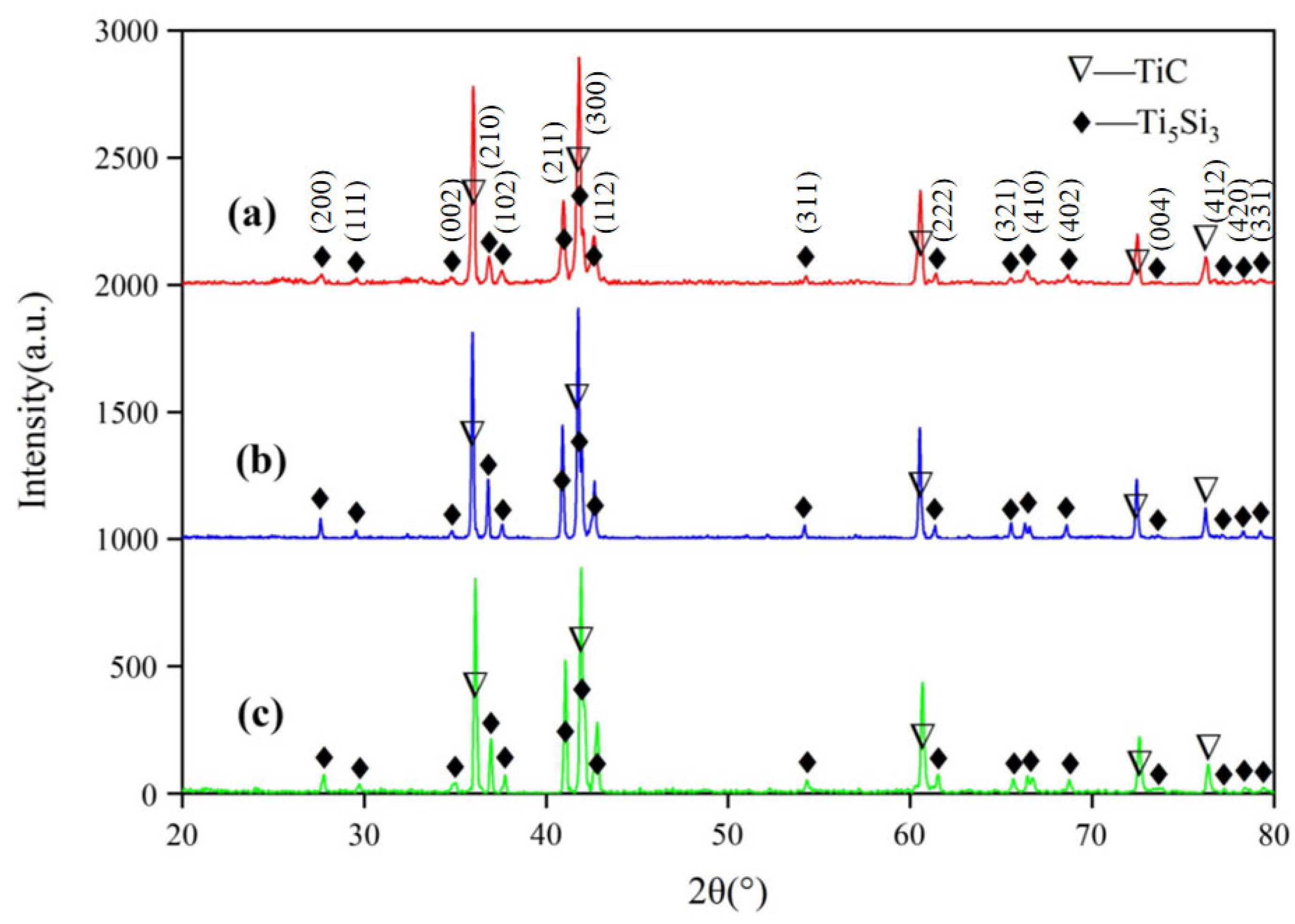
Figure 4 shows the XRD analysis results of the formed phases extracted from the as-cast composites. It is found that Ti and SiC were effectively introduced to promote the formation of TiC and Ti
5Si
3 in all the samples. In addition, there is no other kind of Ti–Si compound synthesized. These results demonstrate that the Ti–SiC mixtures have been completely reacted after adding them into the Cu melts. They also proved that the particle-like phase with a core–shell structure should be Cu@Ti
5Si
3.
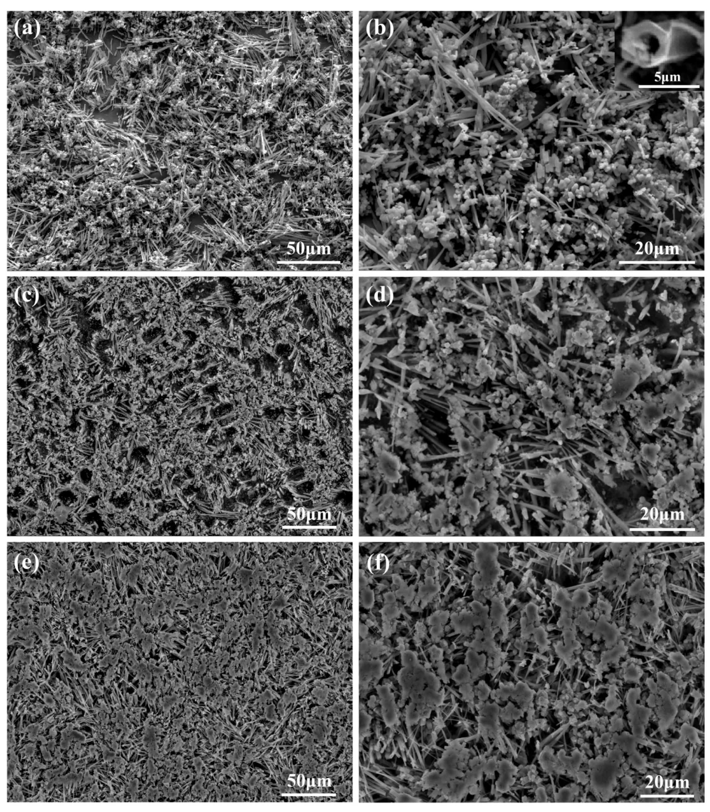
In order to further analyze the morphologies and the distribution of the reaction products, the as-cast composites are then deeply etched to remove the surface Cu matrix. The microstructures of the deeply etching samples are shown in
Figure 5.
It can be seen in
Figure 5a,b that, unlike the microstructure of the as-cast sample, there are only two phases with different morphologies in Cu-4.86Ti-1Si-0.43C. One is particle-like and the other is rod-like, and both of them are alternately distributed in the Cu matrix to form the hybrid reinforcement system together. The mean size of the particles is about 0.8 μm, while the diameter of the rod phase is about 1~2 μm, and the length-to-diameter ratio is about 5~25.
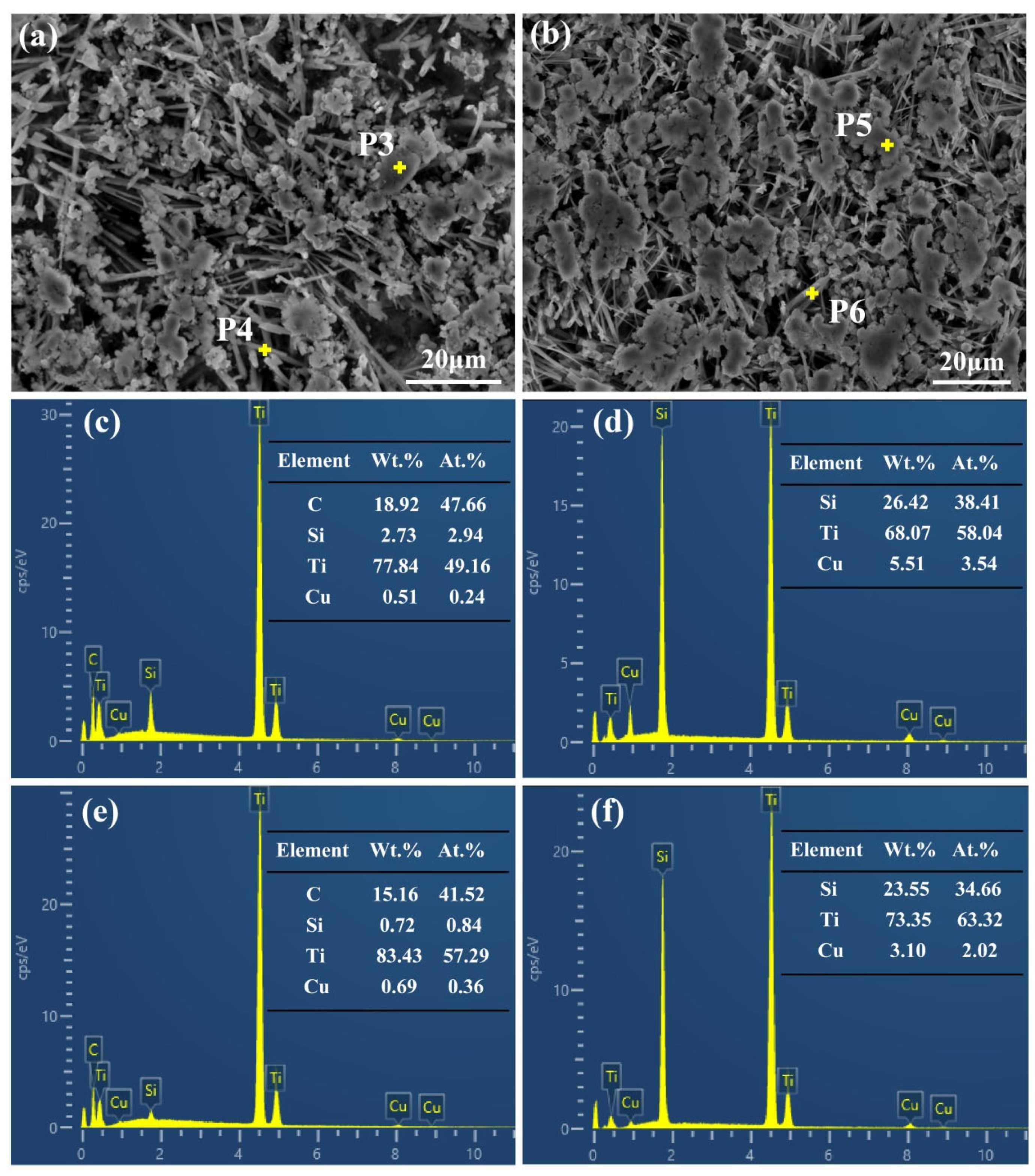
Figure 6 shows the microstructures and EDS point analysis of the deeply etching samples. It can be seen from
Figure 6c,e that the particles are TiC, and the EDS analysis results shown in
Figure 6d,f also confirm that the rod phase is Ti
5Si
3 rods. In addition, it can be noted from
Figure 5d that TiC particles are distributed in clusters, while Ti
5Si
3 rods, which are connected in a network structure, are distributed in clusters. The grid formed by Ti
5Si
3 clusters is filled with the Cu matrix, and each Ti
5Si
3 cluster is connected to form a spatial skeleton structure which is like a bird’s nest. It can be seen in
Figure 5a,b that the spatial structure of TiC and Ti
5Si
3 is not separately distributed, and many TiC particles stick to the Ti
5Si
3 rod.
It is found that many Ti
5Si
3 rods are not solid but hollow, as the insert figure in
Figure 5b shows. It can be seen that the hollow Ti
5Si
3 rod is a hexagonal prism with a cylindrical inner hole, whose cross-section is similar to the shell of the D phase shown in the insert figure in
Figure 1b. It is deduced that those Ti
5Si
3 hollow rods should correspond to the core–shell particle-like D phase whose Cu cores have been completely etched away. The results further confirm that the core–shell phase is Cu@Ti
5Si
3. In addition, it is also demonstrated that the D phase, which seems to be particle-like in the as-cast sample, is actually rod-like. As a result, it can be concluded that all the Ti
5Si
3 have grown into the hexagonal prisms.
As for the Cu-6.8Ti-1.4Si-0.6C and Cu-9.72Ti-2Si-0.86C composites, it can be seen in
Figure 5c–f that they also consist of TiC particles and Ti
5Si
3 rods. It is also noted that the TiC content of Cu-9.72Ti-2Si-0.86C is significantly greater than that of Cu-4.86Ti-1Si-0.43C, as shown in
Figure 5a,e. The results prove that the content of TiC particles increases as the content of Ti–Si–C increases, and it is also found that more Ti
5Si
3 rods with a larger diameter and a smaller length-to-diameter ratio have been formed. It is deduced that those Ti
5Si
3 rods should correspond to the rod-like Ti
5Si
3 (B phase) present in the as-cast samples.
According to the above results, it can be determined that Ti and SiC can be absolutely reacted in the Cu melts, and TiC and Ti
5Si
3 with different morphologies will be synthesized and alternately distributed. As a result, TiC particles and Ti
5Si
3 rods work together as reinforcements to form the hybrid reinforcement system. Regardless of the process, all the previous studies [
23,
24] suggested that Ti
5Si
3 is immediately formed in the Cu melts after Ti–SiC reaction. If so, it is deduced that the size of the Ti
5Si
3 should be significantly increased with the increase in Ti and Si content from Cu-4.86Ti-1Si-0.43C, Cu-6.8Ti-1.4Si-0.6C and Cu-9.72Ti-2Si-0.86C. Nevertheless, the results in this work show that the morphologies and sizes of Ti
5Si
3 are very similar in all samples. Therefore, it is deduced that the Ti
5Si
3 rods should not form in the melt during the holding time but rather crystallize from the melt during the solidification. It has been found in a previous work [
25,
26] that, like another D88 type of an orderly transition metal silicide, Mn
5Si
3, Ti
5Si
3 and Cu can form Cu–Ti
5Si
3 binary eutectic alloys. In the Cu melts, both primary and eutectic Ti
5Si
3 can grow into rod-like hexagonal prisms, which are the same as the Ti
5Si
3 synthesized in our prepared composites. Hence, the more exact formation processes for TiC and Ti
5Si
3 by Ti–SiC reaction in Cu melts in this work should be as follows:
where Si(l) is soluble Si. Then, during the solidification, Ti
5Si
3 is formed in two ways. One is directly crystalizing the melt to form the primary Ti
5Si
3; then, the remaining Ti and Si form the eutectic Ti
5Si
3 by the following eutectic reaction:
More primary Ti5Si3 will be formed by increasing the Ti and Si contents; thus, it is considered that the rod-like Ti5Si3 (B phase) shown in the as-cast samples is the primary Ti5Si3, while the other kind of Ti5Si3 (D phase) is the eutectic Ti5Si3.
As reported in previous works [
26,
27], the growth direction of the orderly transition metal silicide M5Si3, with a D88 crystal structure, is mainly determined by the periodic chain of the M–Si covalent bond due to its larger binding energy compared to that of Si–Si or M–M based on the Hartman–Perdok theory [
28]. This is because the binding energy of the M–Si bond chain is greatest in the <0001> direction perpendicular to the base plane of (0001) due to the atomic arrangements with the shortest distance. As a result, the <0001> direction perpendicular to the base plane of (0001) is the fastest growing direction of all the directions, while, in the direction parallel to the base plane, the growth rate of the <1120> direction is greater than that of the other directions. As a result, M
5Si
3 crystals, such as Mn
5Si
3 and Ti
5Si
3, generally tend to grow into the rod-like hexagonal prism, which is in good agreement with the present work. As for the formation of core–shell prisms with Cu cores in Cu melts, a similar phenomenon is also present for the Mn
5Si
3 in brasses [
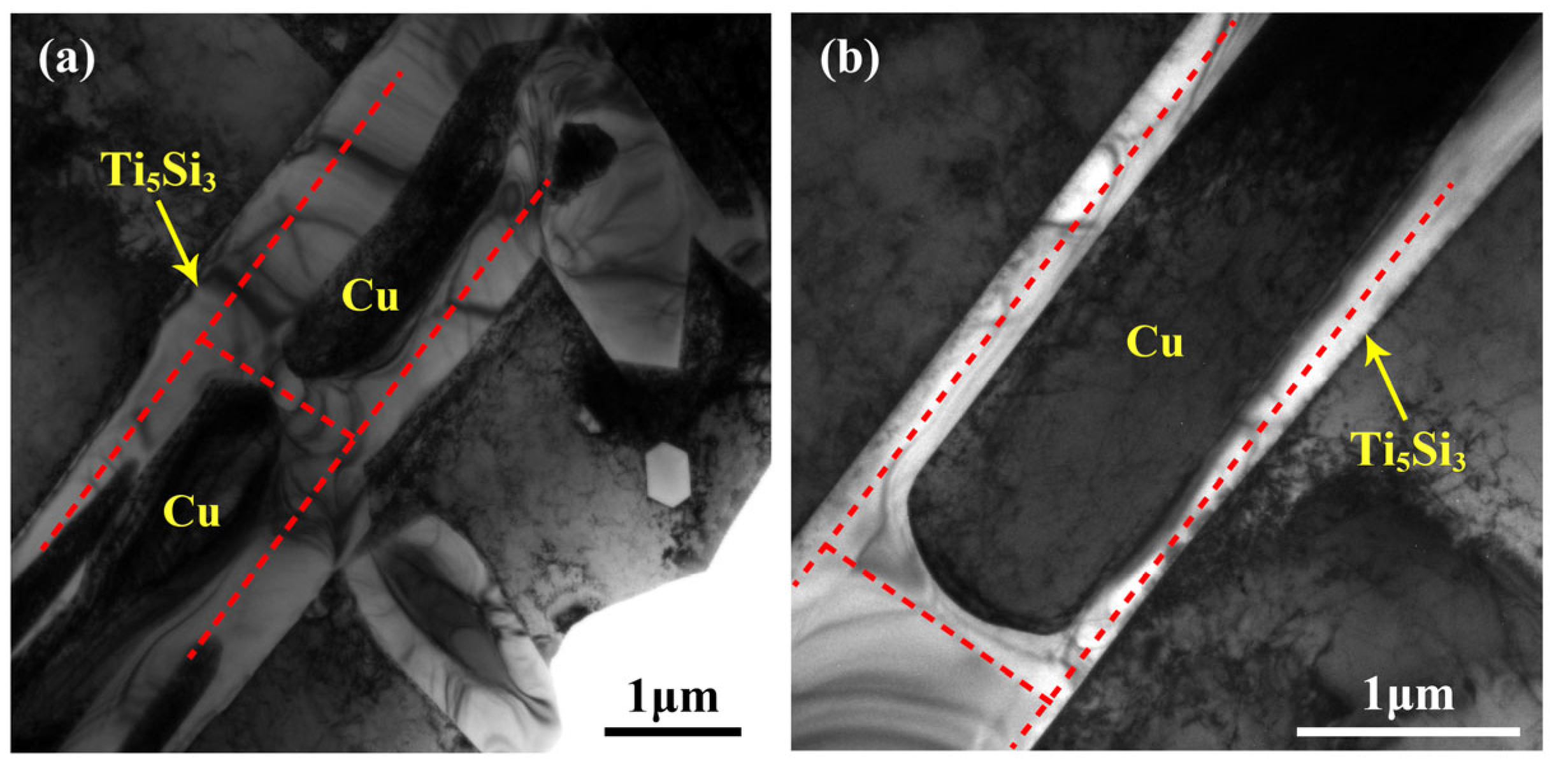
26]. In addition, it is found that the Cu cores in the Cu@Ti
5Si
3 rods do not go through the whole rods but rather part of them, as shown in
Figure 7a. Hence, as seen from the longitudinal section direction, the Ti
5Si
3 rods actually grow into H-shaped shells, and it can also be found that the end face of the Cu core in contact with Ti
5Si
3 is not flat but convex, corresponding to the concave Ti
5Si
3 inner end face. It can be inferred that both the D phase with a core–shell structure and the U-shaped shell in
Figure 7b are part of the H-shaped shell [
25].
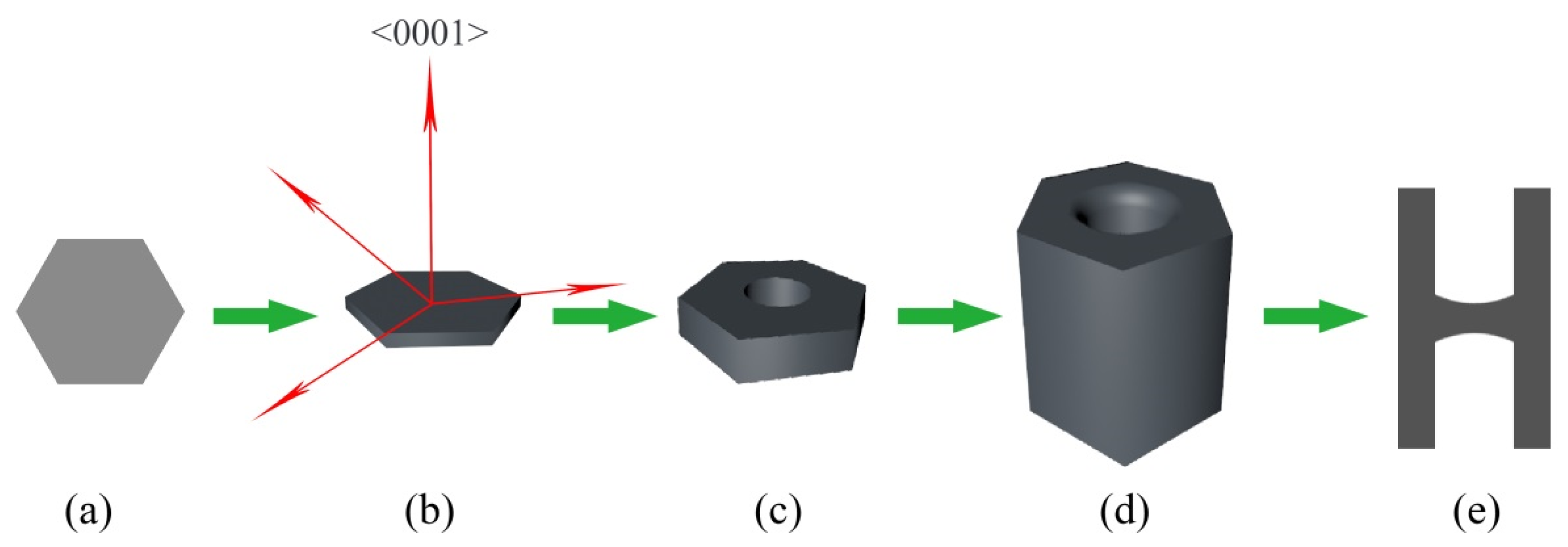
Figure 8 shows the growth processes of the core–shell structure Cu@Ti
5Si
3 in detail. According to the crystal growth characteristics and morphologies of Ti
5Si
3, it is considered that, in the early stage of Ti
5Si
3 formation, the hexagonal chip Ti
5Si
3 with (0001) as the base plane is first formed, as shown in
Figure 8a. That will lead to the depletion of Ti and Si in the surrounding Cu melts, rapidly developing a solid hexagonal sheet, as shown in
Figure 8b. Because of the fastest growth of the <0001> direction perpendicular to the (0001) base plane, the Ti and Si depletion along this direction will also be the worst. As a result, the following growth of Ti
5Si
3 along the <0001> direction will be mainly realized by the horizontal diffusion of the surrounding Ti and Si atoms parallel to the (0001) plane. In this case, the growth of the inner region of the Ti
5Si
3 hexagonal prism will become more difficult than the outside region due to the longer diffusion distance. As a result, the cup-shaped structure will be formed, as shown in
Figure 8c. The formation of the Ti
5Si
3 shell will further hinder the diffusion of Ti and Si from the outside to the inside. The formation of both the circular inner surface and the concave Ti
5Si
3 inner end face proves that the formation of Ti
5Si
3 shells is controlled by the horizontal diffusion of Ti and Si. At the beginning of the formation of the Ti
5Si
3 shell from the prism sheet, because the shell is very thin, it can only retard but not absolutely prevent the diffusion of Ti into the inner region. Now, the whole (0001) plane can still grow along the <0001> direction, but the closer it gets to the center, the slower it grows. Thus, the flat (0001) plane becomes concave, as shown in
Figure 8c. Then, when the Ti
5Si
3 is high enough, Ti and Si will not be diffused from the outside to the inside at all, and the thickness of the Ti
5Si
3 will remain almost constant, as shown in
Figure 8d. In the end, the H-shaped core–shell rods with cylindrical Cu cores are formed, as shown in
Figure 8e. It is considered that the faster the growth rate along the <0001> direction, the thinner the Ti
5Si
3 shell will be. This can be confirmed by comparing the core–shell Ti
5Si
3 with the core–shell Mn
5Si
3 reported in Li’s work [
26]. It is found that the thickness of the shell in this work is much thinner than that in Mn
5Si
3. This should be due to the stronger bonding between Ti and Si, which will give rise to the much faster growth of the <0001> direction for Ti
5Si
3 compared to Mn
5Si
3.
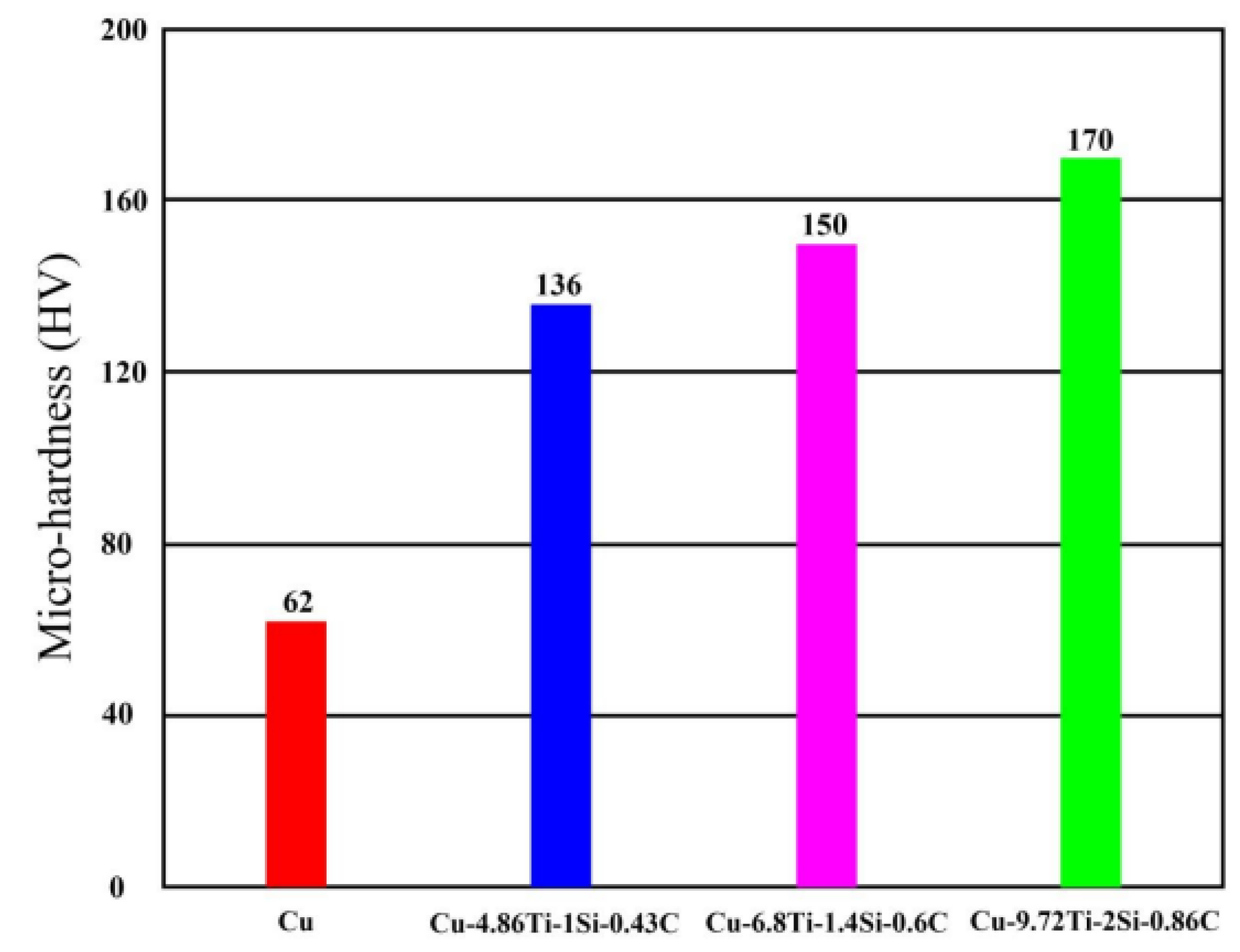
Figure 9 shows the hardness of Cu and the composites prepared. It can be clearly seen that the hardness of the as-cast pure copper is only 62 HV, which is much lower than that of the prepared TiC–Ti
5Si
3 hybrid-reinforced Cu matrix composites. It should be noted that the hardness of the Cu-4.86Ti-1Si-0.43C composites is 136 HV, which is about 2.2 times that of the as-cast copper, and the hardness of the composites also tends to rise with the increase in the TiC–Ti
5Si
3 content. The hardness of the Cu-6.8Ti-1.4Si-0.6C and Cu-9.72Ti-2Si-0.86C composites is 150 HV and 170 HV, respectively, and the maximum hardness is 2.74 times that of the as-cast pure copper. The research [
29] shows that TiC tends to agglomerate in the single TiC/Cu and influences the hardness of composites, and the hardness of Cu-10.68TiC is approximately 105 HV. Compared to the poor dispersion of TiC in TiC/Cu composites, TiC is more evenly distributed in the TiC–Ti
5Si
3 in situ-reinforced Cu composites due to the introduction of Ti
5Si
3. It is obvious that the addition of the TiC–Ti
5Si
3 hybrid-reinforced phase is more helpful for improving the hardness of pure copper. TiC and Ti
5Si
3 have different morphologies, which is beneficial for improving the properties of composites.


