Article

Fabrication of Mn–Co Alloys Electrodeposited on AISI 430 Ferritic Stainless Steel for SOFC Interconnect Applications

by
Saravut Thanedburapasup
1,
Nattapol Wetchirarat
1,
Angkana Muengjai
1,
Watcharapon Tengprasert
2,
Panya Wiman
1,
Thammaporn Thublaor
1,
Putinun Uawongsuwan
1,
Thamrongsin Siripongsakul
1 and
Somrerk Chandra-ambhorn
1,*
1
High Temperature Corrosion Research Centre, Department of Materials and Production Technology Engineering, Faculty of Engineering, King Mongkut’s University of Technology North Bangkok, 1518, Pracharat 1 Road, Wongsawang, Bangsue, Bangkok 10800, Thailand
2
Department of Chemical Engineering, School of Engineering, King Mongkut’s Institute of Technology Ladkrabang, Chalongkrung 1 Road, Lat Krabang, Bangkok 10520, Thailand
*
Author to whom correspondence should be addressed.
Metals 2023, 13(3), 612; https://doi.org/10.3390/met13030612
Submission received: 22 February 2023 / Revised: 7 March 2023 / Accepted: 13 March 2023 / Published: 18 March 2023
(This article belongs to the Special Issue High Temperature Corrosion or Oxidation of Metals and Alloys)

Abstract

:
Mn–Co alloys were electroplated on AISI 430 stainless steel using an electrodeposition technique with the aim to reduce oxidation and chromium volatilization. The electroplating parameters were designed to improve the coating quality. The increased current density with decreased MnSO4 content resulted in a denser coating layer. A sample coated with 0.10 M CoSO4 and 0.50 MnSO4 at 350 mA cm−2 showed the best oxidation resistance after being oxidized at 800 °C for 90 h. The X-ray diffraction (XRD) result revealed that the oxide growth on the surface of the coated samples mainly formed oxides of MnCo2O4, MnCr2O4, and Cr2O3. The chromium volatilization was evaluated by exposing the coated samples to humidified synthetic air at 800 °C for 96 h. The mass flux of Cr volatilization was on the order of 10−11 g cm−2 s−1. Furthermore, different heat treatments in O2 and CO2 atmospheres were compared. Annealing in CO2 at 800 °C for 4 h helped increase the Mn–Co coating density. The relationship between the porosity and its failure behavior was also discussed.

1. Introduction

A fuel cell is a clean power generator that directly and electrochemically converts chemical energy into electrical energy [1]. Solid oxide fuel cells (SOFCs) are considered a renewable energy source [2], and they have many advantages for a wide range of applications because of their high energy conversion efficiency, low greenhouse gas emissions, eco−friendliness, various inlet fuel choices, and long lifetime potential [3,4]. SOFCs comprise two porous electrodes (anode and cathode), separated by a dense layer of solid electrolyte, and an interconnect at each electrode to conduct electricity. To achieve higher power output, multiple SOFCs are heaped as repeated units and called an SOFC stack. An interconnect is a main component that is located between two adjacent repeated units, providing the electrical connection between the SOFCs, and simultaneously transports fuel gases (anode side) and air (cathode side). Ferritic stainless steels are promising materials to use for interconnects, instead of the traditional use of ceramics for interconnects, due to the cost–effectiveness and matching of the thermal expansion coefficient, which is compatible with the electrode materials of the SOFC in the operating temperature range of 650–800 °C [5,6,7,8]. Under this high operating temperature, the exposure of ferritic stainless steels in the cathode and anode atmospheres results in the formation of a chromium oxide (Cr2O3) layer at the surface. The Cr2O3 can then be further oxidized to form volatile Cr species (e.g., CrO3 and CrO2(OH)2) over the oxide scale [9,10,11,12]. The volatile phases are induced by contamination at the cathode, known as Cr poisoning, which degrades SOFC performance [13,14,15,16]. Moreover, continuous exposure to oxidizing atmospheres eventually leads to the formation of a thick oxide scale. The formation and growth of Cr2O3 contribute to an increase in electrical resistance and spallation, which reduce the lifetime of SOFC operation [17].
Protective coatings have been considered to minimize the aforementioned problems, particularly for issues related to oxidation and Cr volatilization. Numerous studies reported that Mn–Co oxide spinel has high electrical conductivity, good oxidation resistance, and low chromium volatilization [18,19,20,21,22,23,24]. Various deposition methods have been proposed to apply Mn–Co oxide spinel on the surface of metallic interconnects, such as slurry coating [18,25], sol–gel [26,27,28], plasma spray [29,30,31], electrophoretic deposition [32,33,34], and electrodeposition [10,11,35,36,37,38,39,40]. Among the deposition methods above, the electrodeposition method is attractive for its economy and feasibility. It allows homogeneous coating over a large area and complex−shaped structures. Electrodeposition is typically used in cathodic deposition processes. Metal ions can be deposited on the cathode by the reduction of metal ions in the electrolyte solution. To form an alloy coating, a small difference of the standard reduction potential is required for multiple−element electrodeposition. If the reduction potentials of multiple elements are significantly different, a chelating agent is often introduced to adjust the reduction potentials of more noble metal to be more negative [36]. S.S. Abd El Rehim et al. [41] suggested that an acidic gluconate solution can be used as a chelating agent for co−electrodeposited Mn–Co alloys because of its environmentally friendly electrolyte. However, the results were different from the literature reported by J. Wu et al. [36]. They studied the effect of plating parameters, such as current density, CoSO4 concentration, and bath composition, to optimize the deposition process. The target coating with Mn–Co near 1:1 could be obtained at a current density of 0.25 A cm−2 with the composition of 0.5 M MnSO4 and 0.1 M CoSO4, 1.0 M H3BO3, 0.7 M gluconate, and 0.1 M (NH4)2SO4. However, the concentration of MnSO4 in the electrolytic bath should be studied to fulfill the investigation of Mn–Co alloy plating. The current density was adjusted in the range of previous work [40] when MnSO4 was changed to give a dense deposited coating layer. Moreover, heat treatment processes were required to improve the densification of the coating layer. Y.-Z. Hu et al. [30] prepared Mn–Co spinel coatings via atmospheric plasma spray followed by heat treatments in reducing and subsequently oxidizing atmospheres. It was found that the adjacent metallic Co particles tended to be bonded together during the reducing process and transformed to Mn–Co spinel after the reoxidation process [30]. The dense coating reduced the inward diffusion of oxygen and the outward migration of chromium [30]. In our previous work, T. Thublaor et al. [40] prepared Mn–Co–electroplated coating layers annealed in argon followed by heat treatment in oxygen. The rather dense Mn–Co spinel coating helped reduce oxidation and chromium volatilization rates after being exposed to O2–5%H2O for up to 96 h at 800 °C, compared to one–step heat treatment in oxygen [11]. It was concluded that the heat treatment process effectively enhanced the densification of the coating, which further reduced the rate of oxidation and chromium volatilization.
In the present work, the electrodeposition method was used to deposit the Mn–Co alloy on AISI 430 stainless steel. The current density and the concentration of MnSO4 in the electrolytic bath were varied, and the optimized result was used to prepare the coating for the oxidation and chromium volatilization test. The oxidation test was studied in air at 800 °C as a simulated SOFC operating condition on the cathode side. Cr species volatilization was also assessed in synthetic air–5%H2O at the same temperature.

2. Materials and Methods

AISI 430 ferritic stainless steel was used in the present study. Its chemical composition was measured using optical emission spectroscopy (OES, Model ARL 3460 from Thermo ELECTRON CORPORATION, Ecublens, Switzerland), providing the element constituent in steels of Fe–16.41Cr–0.79Mn–0.20Si–0.10C–0.05Ni–0.03P in wt.%. The steel sheet was cut into rectangular pieces with sizes of 10.0 × 10.0 mm2 and further cut to have curved ends to avoid spallation after the coating. The samples were ground with SiC paper up to 400 grit and then cleaned in an ultrasonic bath with deionized water (DI water) and ethanol. Finally, they were dried by an air dryer.
For the electrodeposition process, the electrolyte solution was first prepared by mixing 1.00 M H3BO3 with 0.70 M C6H11O7Na in DI water. The 0.10 M CoSO4 was added after stirring the solution until it was homogenous. The solution was further stirred continuously for 30 min and kept at room temperature for 24 h. It was then added with 0.1 M (NH4)2SO4 and MnSO4 under agitation and kept standing for 24 h. The pH was adjusted to 3.0 using 20.0 vol.% H2SO4. The electrodeposition was carried out using a two–electrode system comprising AISI 430 ferritic stainless steel as the cathode and AISI 304 austenitic stainless steel as the anode in the electrolyte solution. The two pieces of AISI 304 steel were cut into a rectangular shape with the dimensions of 25.0 × 30.0 × 1.0 mm3 and ground with SiC paper up to 1000 grits. Before electrodeposition, the surface of the sample was pickled in 25.0 vol.% HCl acid mixing 5.0 vol.% HNO3 acid solution for 3 min and washed in ethanol with an ultrasonic machine and dried in air. Then, the sample was placed parallel to the anode. The current densities of the DC power supply were applied at 150, 250, and 350 mA cm−2. The coating operated at room temperature for 20 min. After coating, the sample was dried for 20 min at 100 °C. To investigate appropriate parameters in Mn–Co electrodeposition, MnSO4 concentrations of 0.50, 0.75, and 1.00 M were used.
For the oxidation test, the samples were placed inside an alumina crucible in a muffle furnace under an ambient air atmosphere at 800 °C for 30, 60, and 90 h. The samples were weighed using a precise balance before and after each test.
To investigate the Cr species volatilization of the coating in the simulated cathode atmospheres, humidified synthetic air (N2–21%O2–5%H2O) was set for study at 800 °C for 96 h. The samples were cut into a rectangular shape (14.2 × 8.0 × 1.0 mm3), which had the curved ends of a semicircle, as described in our previous work [11]. The samples were prepared for electrodeposition and were coated in the abovementioned condition. Each sample was placed on a quartz tube in the horizontal furnace at room temperature. Then, it was heated to 800 °C in Ar. At this temperature, N2–21%O2 was the mixed gas carried into a water flask. A 5% H2O content was controlled by maintaining the water temperature at 31 °C. The temperature was calculated according to the Clausius–Clapeyron equation using the enthalpy of water vaporization, 40,893.0 J mol−1 [42]. The humidified synthetic air was fed into the furnace with a linear flow rate of 1.0 cm s−1. It flowed through the sample surfaces along the furnace tube and condensed in the condenser column, which was additionally connected at an incline to the horizontal furnace tube at the exit. Then, it flowed to the lower end, immersed in water contained in a flask. After the test, the volatilized Cr species condensed in this water flask were collected. This condensate was called a concentration solution. The tube and condenser were cleaned with 0.1 M HCl, and this cleaning solution was added to the concentration solution, which was then taken to analyze the amount of Cr using inductively coupled plasma optical emission spectroscopy (ICP-OES, Agilent 5110, Agilent Technologies, Inc., Santa Clara, CA, USA).
To determine the effects of heat treatment atmospheres on Mn–Co spinel formation, the adhesion failure of the coating was studied. A bare steel sheet with a thickness of 1.0 mm was cut into pieces with a total length of 50 mm for the tensile test. The length and width of the gauge were 16 mm and 3 mm, respectively. This experiment has been detailed in our prior work [43]. Then, the sample surface was finished and coated with the same condition used previously. After being coated, the samples were loaded into a quartz tube in a horizontal furnace with O2 and CO2 atmospheres at 800 °C for 4 h for each condition. The linear velocity of the flowing gas was 1.0 cm s−1. The sample was set in a tensile testing machine equipped with a high–speed CCD camera. The test was conducted at room temperature. A crosshead speed was set at 5 mm min−1 with a tensile loading of 10 kN. The experimental force and deformation displacement were converted to stress–strain curves. During the tensile testing, the surface of the sample was monitored in situ using the CCD camera. The failure of the coating on the sample surface was observed and recorded as a video.
Standard scanning electron microscopy (SEM, QUANTA 450 from FEITM, Hillsboro, OR, USA) equipped with energy dispersive spectroscopy (EDS, EDAX-AMETEK, Inc., Berwyn, PA, USA) was used to characterize the morphology of the coating surface and cross–sectional images. EDS was used to determine the elemental composition of the coating sample. The formed phases in the coating were investigated using X-ray diffraction (XRD, Rigaku, Tokyo, Japan) with Cu Kα (α = 1.5406 Å) radiation. The diffraction pattern measured from the studied samples was matched with the standard XRD patterns organized by the International Center for Diffraction Data (ICDD, Newtown Square, PA, USA).

3. Results and Discussion

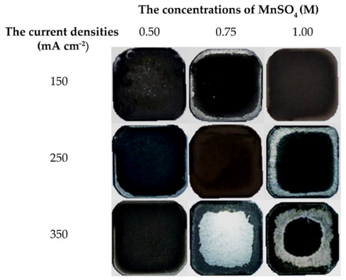
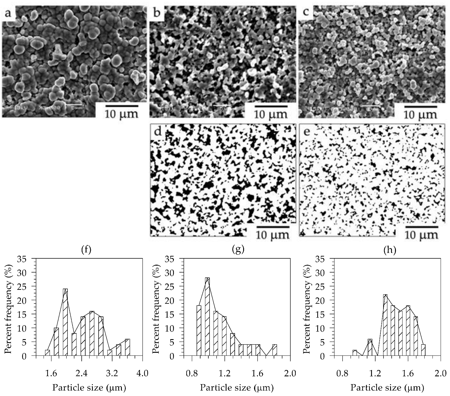
3.1. Surface Morphology of the As–Coated Sample

Figure 1 shows top–view photographs of the sample surfaces after coating using the electrodeposition technique with different concentrations of MnSO4 (M) and the applied current densities (mA cm−2). The conditions of 1.00 M MnSO4 at 150 mA cm−2, 0.75 M MnSO4 at 250 mA cm−2, and 0.50 M MnSO4 at 350 mA cm−2 are well deposited without spallation. Among the coating conditions shown in Figure 1, the electrolytic bath with 0.5 M MnSO4 provides dense coating with increasing current density. However, one sample has some spallation at the edge of the steel sample at low current density. To observe the microscopical morphology of the surface, the secondary electron image reveals a dense deposit with large grains of packed particles for the sample with the coating condition of 1.00 M MnSO4 at 150 mA cm−2 (Figure 2a), while Figure 2b,c exhibit small grains of particles for both conditions of 0.75 M MnSO4 at 250 mA cm−2 and 0.50 M MnSO4 at 350 mA cm−2. They have spongy or porous morphology. The porosity is evaluated and analyzed using ImageJ, as shown in Figure 2d,e. The values are 28.15% and 13.93%. In addition, the histograms of particle sizes on the coating are shown in Figure 2f–h. The average particle size of the as–coated sample produced using 1.00 M MnSO4 at 150 mA cm−2 was 2.43 μm. When applying the current densities of 250 mA cm−2 in 0.75 M MnSO4 (Figure 2g) and 350 mA cm−2 in 0.50 M MnSO4 (Figure 2h), the average particle sizes were 1.13 μm and 1.47 μm, respectively. It was noticed that increasing the current density from 250 to 350 mA cm−2 resulted in the finer particle size and the less porous coating. These findings show that increasing the current density above 150 mA cm−2 causes the morphology to shift from large grains to small grains of packed particles.
J. Wu et al. [36] studied Mn–Co electrodeposition in a similar Mn–Co sulfate bath. They reported that a spongy or porous morphology of the as–coated sample was obtained with the presence of a metal hydroxide—Co(OH)2 and Mn(OH)2—when a current density of at least 200 mA cm−2 was applied. Given that Co2+ and Mn2+ from the electrolytic solution receive electrons at the cathode, Co and Mn solids are deposited on the steel surface according to Reactions (1) and (2) [36].
Co 2 + + 2 e Co ( s )
Mn 2 + + 2 e Mn ( s )
Meanwhile, the water can be split by adding hydrogen gas (as bubbles) and hydroxide ions ( OH ) as follows in Reaction (3). Co and Mn ions can react with hydroxide ions, yielding metal hydroxide as the reaction product [36].
2 H 2 O ( l ) + 2 e H 2 ( g ) + 2 OH
The hydrogen bubbles formed on the surface electrode from Reaction (3) inhibit the reduction reaction and contribute to the coating porosity.

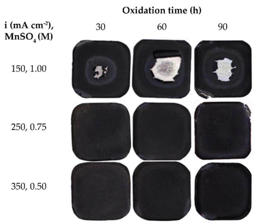
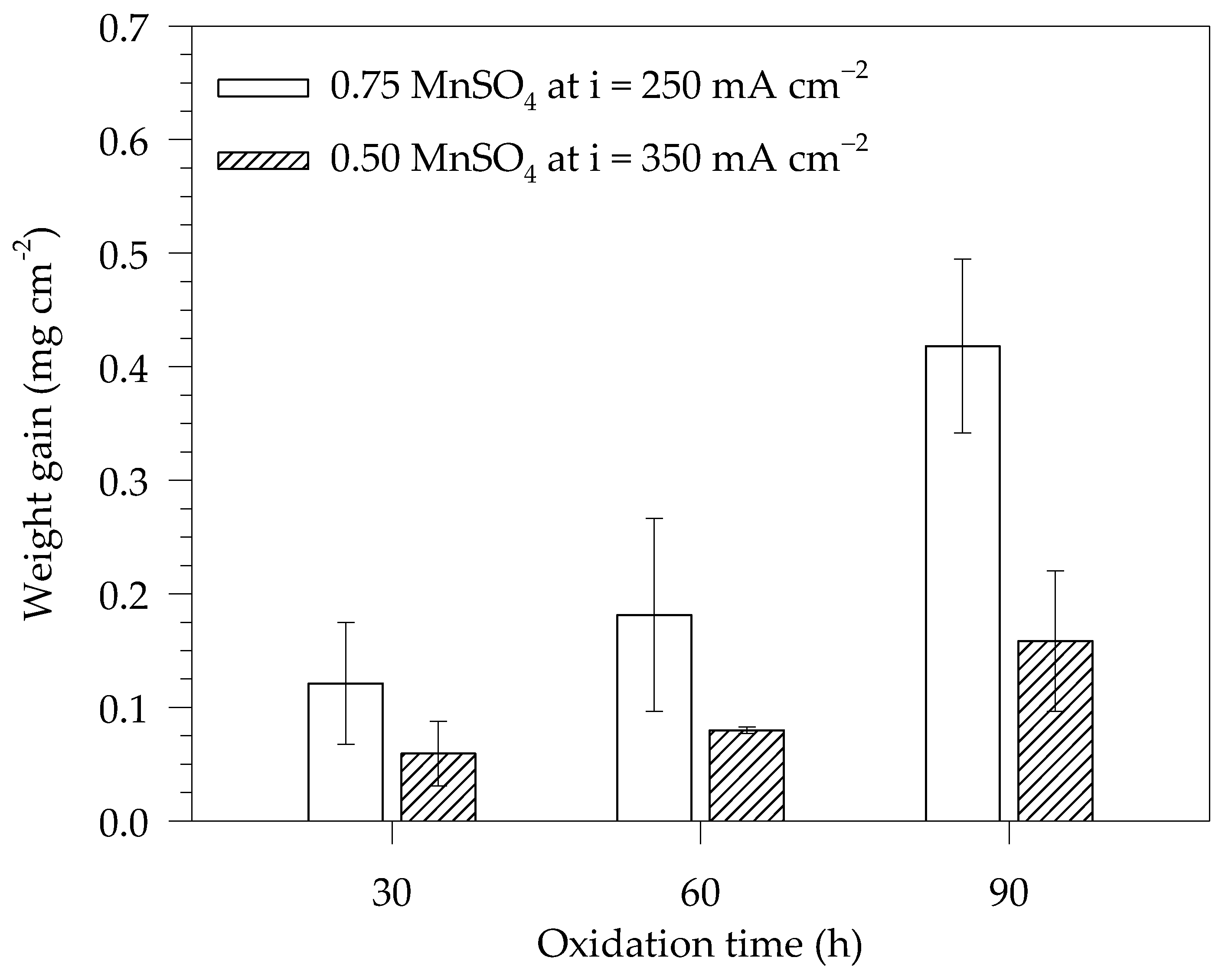
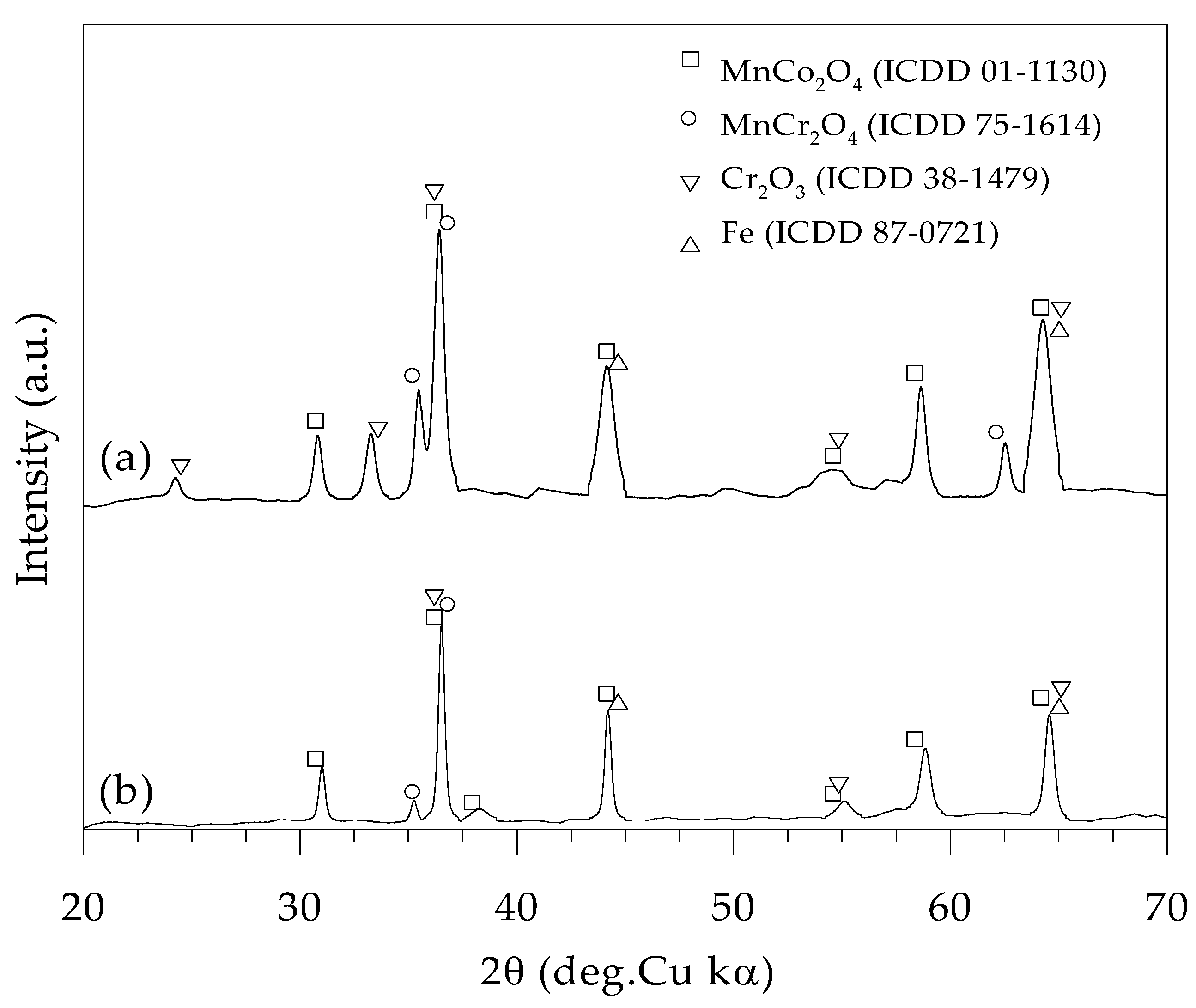
3.2. Oxidation Test and XRD Phase Identification

From Figure 1, the three dense coatings were selected to investigate oxidation durability. Figure 3 shows the top–view photographs of the surface coating after oxidizing in air at 800 °C for 30, 60, and 96 h. Spallation can be seen in every oxidation period for the coating under 1.00 M MnSO4 at 150 mA cm−2. Other conditions show fine coating layers covering the surfaces with spallation or peeling off. The weight of the coated samples without spallation before and after the oxidation test was investigated and converted to the weight per unit surface area; this was called the weight gain ( Δ m / A ). This quantity is plotted as a function of oxidation time (t) in Figure 4. The mass gain of the sample coated with 0.50 M MnSO4 at 350 mA cm−2 is lower than that coated with 0.75 M MnSO4 at 250 mA cm−2. It decreases by 2.0– to 2.6–fold after exposure in the oxidation test from 30 h to 90 h.
It may be related to oxygen adsorption caused by being exposed to ambient air, which is also the cause of porosity in the coating. Figure 2d,e provide the porosity of the as–coated samples with 0.75 M MnSO4 at 250 mA cm−2 and 0.50 M MnSO4 at 350 mA cm−2. The weight gain and porosity decrease similarly by 75%. In this case, it is implied that the oxidation rate is dominated by the porosity of the coating. In the present work, the sample coated with an electrolytic solution of 0.10 M CoSO4 + 0.50 MnSO4 at an applied current density of 350 mA cm−2 showed the best oxidation resistance.
To identify the phase formation after oxidation at 800 °C in air for 30 h, the XRD result is reported in Figure 5a for the sample with the best oxidation resistance. We detected the presence of MnCo2O4 (ICDD 01-1130), MnCr2O4 (ICDD 75-1614), Cr2O3 (ICDD 38-1479), and Fe (ICDD 87-0721), a cubic I m–3 m ferritic phase as a steel substrate. Furthermore, to assess the thermodynamic stability of the oxides formed, the equilibrium oxygen partial pressure was calculated using the following formula: p O 2 , e q = exp ( Δ G ° / R T ) . Δ G ° is the standard Gibbs free energy of oxide formation, while T and R are the absolute temperature (K) and the universal gas constant (8.314 J mol−1 K−1), respectively. Using Hess’s law, the standard Gibbs free energy of MnCr2O4 formation from their constituent elements and oxygen can be obtained from the standard Gibbs free energy of MnCr2O4 formation from Cr2O3 and MnO provided by Holcomb and Alman [44], and the standard Gibbs free energies of Cr2O3 and MnO formations which were calculated from the standard enthalpy and entropy of their constituent elements reported by Kubaschewski and Alcock [45]. For MnCo2O4 formation, Petric and Ling provide a standard Gibbs free energy of −30.3 kJ [22]. Using this assumption, it is derived from the reaction of Co3O4 and Mn3O4 [46]. Δ G ° of MnCo2O4 formation was calculated from its constituent elements and oxygen. The calculating method is similar to that of MnCr2O4 formation. The data for investigating Δ G ° of Co3O4 and Mn3O4 formation were obtained by Kubaschewski and Alcock [45]. At 800 °C, the standard Gibbs free energies per 1 mol oxygen of MnCr2O4, Cr2O3, and MnCo2O4 formation are −604.58, −560.72, and −343.70 kJ, respectively. These energies provide equilibrium oxygen partial pressures of 3.69 × 10⁻³⁰, 5.04 × 10⁻²⁸, and 1.85 × 10⁻¹⁷ bar for MnCr2O4, Cr2O3, and MnCo2O4, respectively. The actual oxygen partial pressure in the ambient air was 0.21 bar. This result is much higher than the equilibrium oxygen partial pressures of MnCr2O4, Cr2O3, and MnCo2O4, indicating that the formation of these oxides in air is thermodynamically possible.

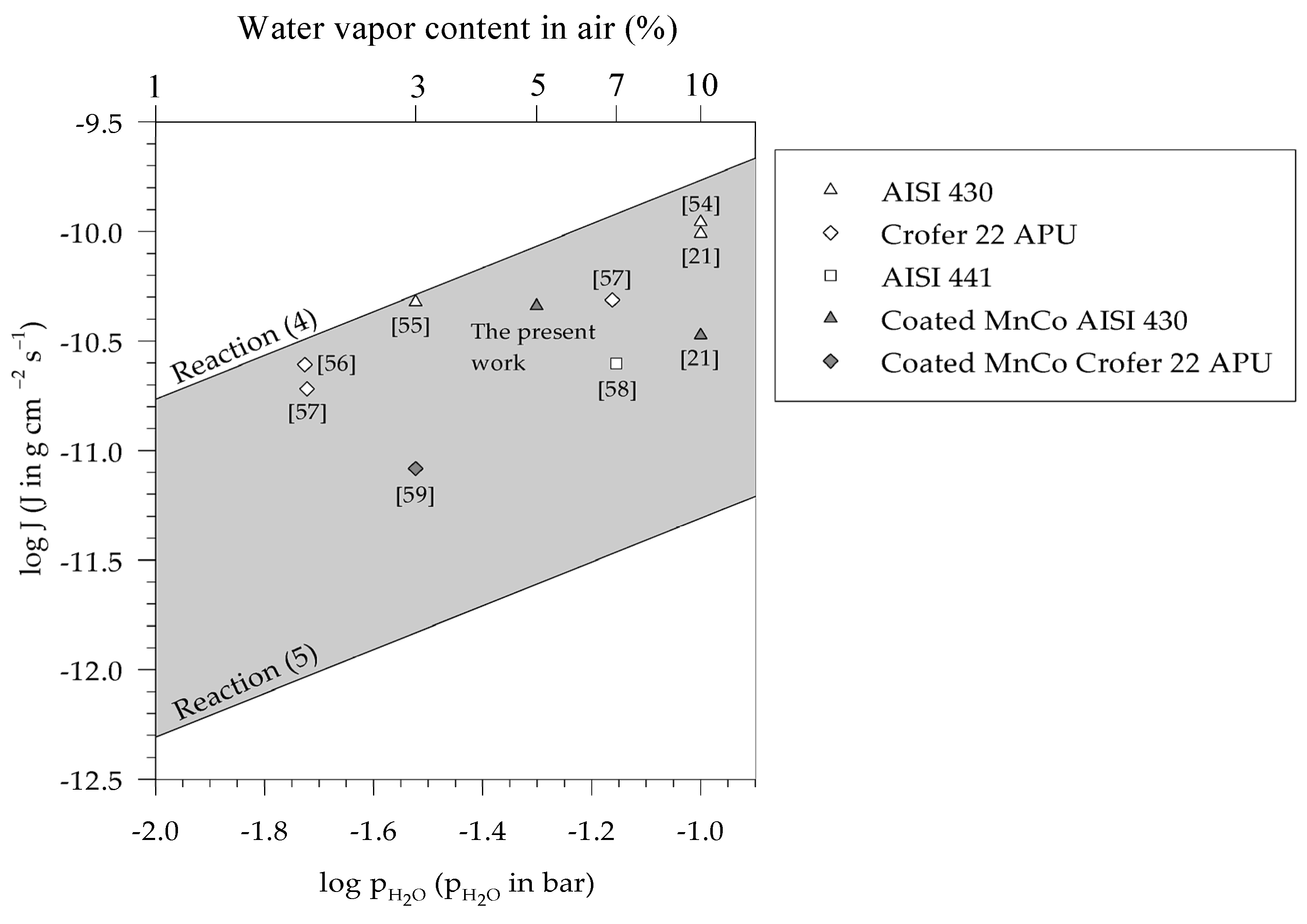
3.3. Cr-Species Volatilization

At SOFC operating temperatures, the chromia can be volatilized, and the volatile species consequently contaminates the SOFC cathode, resulting in cell performance deterioration due to chromium poisoning [13,14,15,16]. The water vapor content in air (cathode side) is 3.6% at an ambient temperature of 25 °C, calculated using the standard thermodynamic data [45]. Moreover, it was reported that the CrO2(OH)2 is the dominant volatile species than CrO3 under the humidified oxidizing atmosphere at a temperature lower than 1500 °C [9,10,11,12]. To hasten the volatilization of Cr–species, 5% water vapor content was added to air. The presence of oxides containing chromium, such as Cr2O3 and MnCr2O4, is detected on the surface of stainless steels exposed to air containing water vapor [47,48]. Figure 5b, the XRD result for the sample coated with 0.10 M CoSO4 + 0.50 MnSO4 at 350 mA cm−2 after oxidation at 800 °C in humidified synthetic air (N2–21%O2–5%H2O) for 96 h, shows that MnCr2O4 (ICDD 75-1614), Cr2O3 (ICDD 38-1479), MnCo2O4 (ICDD 01-1130), and Fe (ICDD 87-0721) are present. As Cr2O3 and MnCr2O4 are contained in the coatings, volatile Cr species can be liberated. The volatilized Cr–rich oxide can yield CrO2(OH)2 according to Reactions (4) and (5) [9,10,44,49].
1 2 Cr 2 O 3 ( s ) + 3 4 O 2 ( g ) + H 2 O ( g ) CrO 2 ( OH ) 2 ( g )
1 2 MnCr 2 O 4 ( s ) + 3 4 O 2 ( g ) + H 2 O ( g ) CrO 2 ( OH ) 2 ( g ) + 1 2 MnO ( s )
Young and Pint [50] presented the mass flux of Cr loss in terms of volatilization (J) as the following Equation (6) to predict the rate of Cr species volatilization on a flat surface [50].
J = M C r k m R T ( p s p b )
where M C r is the atomic mass of Cr (51.9962 g mol−1 [42]), k m is the mass transport coefficient (cm s−1), R is the universal gas constant (8.314 J mol−1 K−1), T is the absolute temperature (K), and p s and p b are the partial pressure of gas volatile species at the solid surface and in the bulk gas, respectively. By considering that p b is insignificant compared with p s , it is neglected in Equation (6). Additionally, k m is defined as Equation (7) [49,50]:
k m = 0.664 ( ρ A V 3 D A B 4 μ A L 3 ) 1 6
where ρ A is the density of the solvent gas (g cm−3), V is the linear velocity of the bulk gas (cm s−1), L is the sample length (cm), μ A is the viscosity of the solvent gas (g cm−1 s−1), and D A B is the binary gas diffusion coefficient (cm2 s−1) between the solvent gas (air) and the Cr(VI) species gas (CrO2(OH)2). μ A and D A B are given as follows [50,51].
μ A = 2.6693 × 10 5 ( M A T σ A 2 Ω μ , A )
D A B = ( 1.858 × 10 3 ) T 3 2 σ A B 2 Ω μ , A B 1 M A + 1 M B
From the equation above, σ A is the collision diameter of the gas solvent (Å), and Ω μ , A is the dimensionless collision integral for viscosity at the absolute temperature. Ω μ , A can be calculated from T k / ε as reported by Bird et al. [52]. ε is the characteristic energy of the interaction between molecules, and k is Boltzmann’s constant. The values of σ and ε / k are given in Table 1. σ A B and Ω μ , A B are the collision diameter and the collision integral for the binary gas, which can be calculated as Equations (10) and (11), respectively [50,53].
σ A B = 1 2 ( σ A + σ B )
ε A B k = ( ε A k · ε B k ) 1 2
p s is partial pressure of CrO2(OH)2 (bar) over Cr2O3 and MnCr2O4, which according to Reactions (4) and (5) can be obtained by Equations (12) and (13) [49].
p CrO 2 ( OH ) 2 = a C r 2 O 3 1 / 2 p O 2 3 / 4 p H 2 O exp ( Δ G 4 ° R T )
p CrO 2 ( OH ) 2 = ( a M n C r 2 O 4 a M n O ) 1 2 p O 2 3 / 4 p H 2 O exp ( Δ G 5 ° R T )
In case of air, the partial pressure of oxygen is 0.21 ( p O 2 = 0.21 ) . The activities (a) of solid phases are equal to unity ( a = 1 ) . Δ G 4 ° is the standard Gibbs free energy of Reactions (4) as 49,150 + 45.13 T J, whereas Δ G 5 ° is 88,142.50 + 38.33 T J for the standard Gibbs free energy of Reactions (5), the thermodynamic data taken from the literature [9,11,44,45]. By inserting Equations (7), (12), and (13) into Equation (6), the mass flux (J) of Cr volatilization at different water vapor contents in air can be calculated and drawn on a logarithmic scale, as shown in Figure 6.
This figure plots mass fluxes of Cr volatilization from AISI 430 stainless steel [21,54,55], Crofer 22 APU [56,57], and AISI 441 stainless steel [58], after oxidation in air with different water vapor contents (air–H2O). The mass fluxes of Cr volatilization from stainless steel are found in the gray zone, the region between a higher mass flux of Cr volatilization from MnCr2O4 and a lower mass flux from Cr2O3. Thus, the mass flux of Cr volatilization from stainless steel is obtained from the mass flux of Cr volatilization from MnCr2O4 combined with Cr2O3 [11]. All Mn–Co spinel–coated samples [21,59] have lower volatile Cr species than uncoated samples [21,54,55]. In this work, the average chromium volatilization rate of Mn–Co spinel–coated samples from two trials of the experiment is 4.39 × 10⁻¹¹ g cm−2 s−1 after exposure to synthetic air–5%H2O for 96 h. The coating can reduce the volatilized rate compared to uncoated AISI 430 stainless steels. This comparison implies that the Mn–Co spinel coating potentially could reduce the chromium volatilization from the stainless steel.

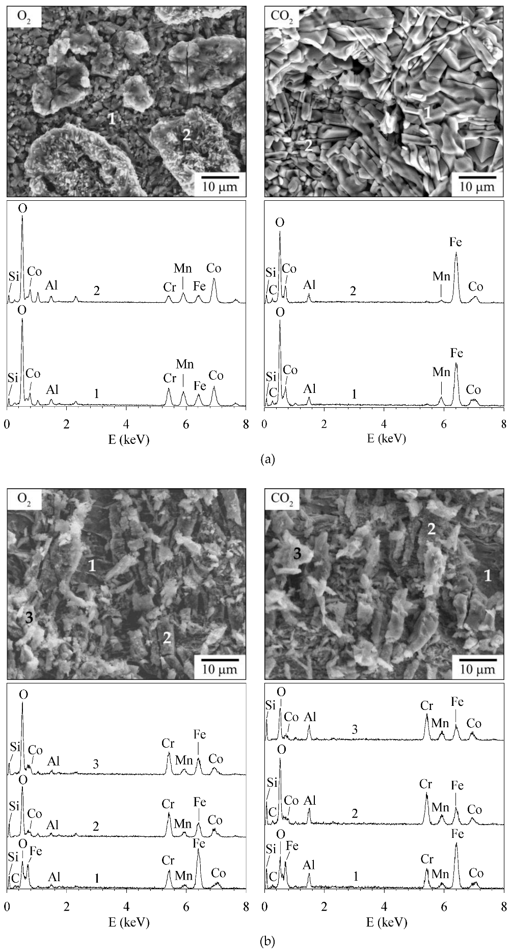
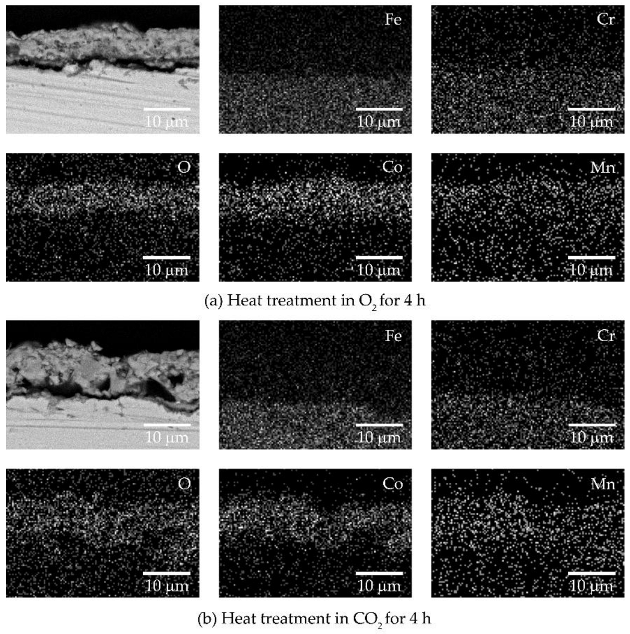
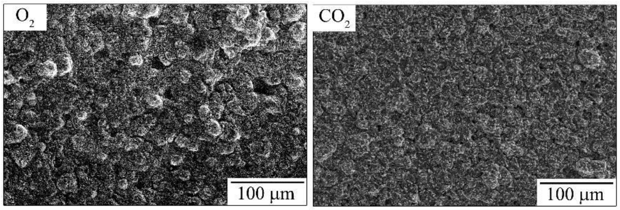
3.4. O2 and CO2 Heat Treatment Atmospheres of the Coating Process

For the coating failure after oxidation in different heat treatment atmospheres, the plating condition for a dense coat and the best oxidation resistance, mixing 0.10 M CoSO4 with 0.50 MnSO4 at a current density of 350 mA cm−2, was applied to AISI 430 stainless steel. The as–coated sample was heated at 800 °C for 4 h in O2 and CO2 atmospheres. During tensile testing, the failure was monitored using a high–speed CCD camera. The displacement of deformation was related to the strain of the sample and failure due to spallation. The first and continuing failure activities of the coating in the video were observed. From the video record, the average strain at first spallation is 0.59%, s.d. = 0.27%, for the sample heat treated in CO2, indicating good resistance to failure, and 0.18%, s.d. = 0.05%, for the sample treated in an O2 atmosphere. Figure 7a shows SEM images of the coated samples after annealing in O2 and CO2, after straining by 1%. Cracks can be seen on the coating layer of both samples. The EDS peaks of Mn, Co, and O were detected on both spots 1 and 2. Figure 7b shows SEM images of the areas near the broken necks after tensile testing. Plates or flakes of cracked coating layers are observed as a result of the applied load action. Some cracked layers remain on the surfaces, and the morphology is identical for both samples. The EDS spot analyzed results are shown in Figure 7b. For both samples, a strong detection of the Fe peak and a relatively low intensity of the O peak of spot 1 indicate the detection of a steel substrate. The relatively high intensity of O peaks of spots 2 and 3 of the cracked layers accompanied by Mn and Co detection corresponds to the coating layer.
In addition, the samples with post−heat treatment without tensile testing were cross−sectioned and analyzed using SEM and EDS mapping. The results are shown in Figure 8a,b for heat treatment in O2 and CO2, respectively. Both samples have continuous coating layers containing Mn, Co, and O. Furthermore, only a few porosities are apparent, with small cracks in the coating and at the coating/steel interface. The porosity of the sample annealed in O2 and CO2 seems to be difficult to observe from the cross−sectional SEM images. Figure 9 shows top−view surface SEM images of the samples annealed in CO2 in Figure 9 (right), which have lower porosity than that annealed in O2 in Figure 9 (left). From this evidence, it can be explained that the load from the tensile test is transferred to the Mn–Co coating layer. The load demolished the cohesive and adhesive binding forces of the coating, which appears as a mixed mode between cracking and spallation within the coating and coating/substrate interface [60]. Therefore, the heat treatment of the coating in a CO2 atmosphere affects a dense coating by helping it avoid voids and gaps.
As a matter of discussion, the presence of intermetallic compounds at the interface between two different phases could reduce the interfacial adhesive strength [61,62,63]. In the case of stainless steel, the presence of Fe–Mo intermetallic compounds at the interface between the AISI 444 (Fe–18Cr–Mo–Ti–Nb) and its thermal oxide scale was found to help provoke the spallation [61]; however, such a phase was not observed here. The detachment of the coating from the studied steel, here, should be primarily due to the polishing and mounting processes. In addition, the coating layer can serve as a barrier to inhibit the oxygen inward diffusion and the outward diffusion of cationic species from the substrate [11,64,65]. As for the 800H Ni–based alloy oxidized at high temperature, J. Yang et al. [65] have recently found that the Cr coating could retard the Fe outward diffusion at a high temperature. For the AISI 430 stainless steel, we previously applied the Mn–Co oxide through slurry coating and conducted the oxidation test at 800 °C in O2–5%H2O [64]. It was found that the coating could help reduce the outward diffusion of Fe from the steel substrate, and Cr loss due to volatilization also tended to be reduced, compared with the result reported in literature [11]. We not only developed the Mn–Co coating through the slurry method but also through the electroplating method, and also found the beneficial effect that the Mn–Co coating had on reducing the Cr volatilization, as presented in Figure 6.

4. Conclusions

The electrodeposition of Mn–Co alloys was conducted on AISI 430 stainless steels. The effect of electroplating parameters on the coating quality was primarily studied. Furthermore, the samples were oxidized in air and humidified synthetic air (N2–21%O2–5%H2O) at 800 °C to investigate oxidation resistance and Cr species volatilization, respectively. Heat treatments in O2 and CO2 atmospheres for 4 h at 800 °C were performed to investigate the failure of the coating in the last section. The following conclusions can be drawn.
1. Various electroplating current densities (150, 250, and 350 mA cm−2) and concentrations (0.50, 0.75, and 1.00 M MnSO4) were investigated. An increased current density with a lower MnSO4 concentration was required for a dense coating with good oxidation resistance without spallation. The optimized conditions are 1.00 M MnSO4 at 150 mA cm−2, 0.75 M MnSO4 at 250 mA cm−2, and 0.50 M MnSO4 at 350 mA cm−2.
2. The sample coated with an electrolyte solution of 0.10 M CoSO4 mixed with 0.50 MnSO4 at an applied current density of 350 mA cm−2 demonstrated the best oxidation resistance in air. The low weight gain was a result of the lower porosity of the coating.
3. After 96 h of exposure, the volatilization of the Cr species of the coated samples was measured in humidified synthetic air at 800 °C. The results were on the order of 10−11 g cm−2 s−1, in good agreement with the volatilization of Cr2O3 and MnCr2O4 reported in the literature.
4. Heat treatments in O2 and CO2 atmospheres were conducted to convert Mn–Co alloys to form the spinel of the coatings. The samples annealed in CO2 had low porosity or void formation, resulting in greater resistance to failure than those annealed in O2.

Author Contributions

S.T.: methodology, investigation, and formal analysis; N.W.: methodology, investigation, and formal analysis; A.M.: methodology, investigation, and formal analysis; W.T.: formal analysis; P.W.: methodology, investigation, formal analysis, writing—original draft preparation, writing—review and editing, and funding acquisition; T.T.: investigation, formal analysis, writing—original draft preparation, writing—review and editing, funding acquisition, and supervision; P.U.: formal analysis and supervision; T.S.: writing—original draft preparation, writing—review and editing, and supervision; S.C.-a.: formal analysis, writing—original draft preparation, writing—review and editing, funding acquisition, and supervision. All authors have read and agreed to the published version of the manuscript.

Funding

This research was funded by the Thailand Research Fund, the National Research Council of Thailand, grant number PHD/0156/2558, the National Science, Research, and Innovation Fund (NSRF), and King Mongkut’s University of Technology North Bangkok (Contract no. KMUTNB-FF-66-22).

Data Availability Statement

The data presented in this study are available upon request from the corresponding author.

Conflicts of Interest

The authors declare no conflict of interest.

References

  1. Huang, K.; Goodenough, J.B. Solid Oxide Fuel Cell Technology: Principles, Performance and Operations, 1st ed.; Woodhead Publishing Limited: Cambridge, UK, 2009. [Google Scholar]
  2. Alaedini, A.H.; Tourani, H.K.; Saidi, M. A review of waste-to-hydrogen conversion technologies for solid oxide fuel cell (SOFC) applications: Aspect of gasification process and catalyst development. J. Environ. Manag. 2023, 329, 117077. [Google Scholar] [CrossRef] [PubMed]
  3. Stambouli, A.B.; Traversa, E. Solid oxide fuel cells (SOFCs): A review of an environmentally clean and efficient source of energy. Renew. Sustain. Energy Rev. 2002, 6, 433–455. [Google Scholar] [CrossRef]
  4. Li, H.; Wei, W.; Liu, F.; Xu, X.; Li, Z.; Liu, Z. Identification of internal polarization dynamics for solid oxide fuel cells investigated by electrochemical impedance spectroscopy and distribution of relaxation times. Energy 2023, 267, 126482. [Google Scholar] [CrossRef]
  5. Yang, Z. Recent advances in metallic interconnects for solid oxide fuel cells. Int. Mater. Rev. 2008, 53, 39–54. [Google Scholar] [CrossRef]
  6. Wu, J.; Liu, X. Recent development of SOFC metallic interconnect. J. Mater. Sci. Technol. 2010, 26, 293–305. [Google Scholar] [CrossRef]
  7. Guo, P.; Lai, Y.; Shao, Y.; Zhang, Y.; Wang, Y. Thermal growth Cu1.2Mn1.8O4 spinel coatings on metal interconnects for solid oxide fuel cell applications. Metals 2017, 7, 522. [Google Scholar] [CrossRef] [Green Version]
  8. Chevalier, S.; Combemale, L.; Popa, I.; Chandra-ambhorn, S.; Chandra-ambhorn, W.; Promdirek, P.; Wongpromrat, P. Development of SOFC interconnect stainless steels. Solid State Phenom. 2020, 300, 135–156. [Google Scholar] [CrossRef] [Green Version]
  9. Opila, E.J.; Myers, D.L.; Jacobson, N.S.; Nielsen, I.M.; Johnson, D.F.; Olminsky, J.K.; Allendorf, M.D. Theoretical and experimental investigation of the thermochemistry of CrO2(OH)2(g). J. Phys. Chem. A 2007, 111, 1971–1980. [Google Scholar] [CrossRef]
  10. Wongpromrat, W.; Thaikan, H.; Chandra-ambhorn, W.; Chandra-ambhorn, S. Chromium vaporisation from AISI 441 stainless steel oxidised in humidified oxygen. Oxid. Met. 2013, 79, 529–540. [Google Scholar] [CrossRef]
  11. Thublaor, T.; Chandra-ambhorn, S. High temperature oxidation and chromium volatilisation of AISI 430 stainless steel coated by Mn-Co and Mn-Co-Cu oxides for SOFC interconnect application. Corros. Sci. 2020, 174, 108802. [Google Scholar] [CrossRef]
  12. Wiman, P.; Thublaor, T.; Rojhirunsakool, T.; Bidabadi, M.H.S.; Yang, Z.-G.; Siripongsakul, T.; Chandra-ambhorn, W.; Chandra-ambhorn, S. Corrosion behaviour of AISI 430 stainless steel in O2-40%H2O at 800 °C. Corros. Sci. 2022, 203, 110323. [Google Scholar] [CrossRef]
  13. Hilpert, K.; Das, D.; Miller, M.; Peck, D.H.; Weib, R. Chromium vapor species over solid oxide fuel cell interconnect materials and their potential for degradation processes. J. Electrochem. Soc. 1996, 143, 3642–3647. [Google Scholar] [CrossRef]
  14. Fergus, J.W. Metallic interconnects for solid oxide fuel cells. Mater. Sci. Eng. A 2005, 397, 271–283. [Google Scholar] [CrossRef]
  15. Fergus, J.W. Effect of cathode and electrolyte transport properties on chromium poisoning in solid oxide fuel cells. Int. J. Hydrogen Energy 2007, 32, 3664–3671. [Google Scholar] [CrossRef]
  16. Jiang, S.P.; Chen, X. Chromium deposition and poisoning of cathodes of solid oxide fuel cells—A review. Int. J. Hydrogen Energy 2014, 39, 505–531. [Google Scholar] [CrossRef]
  17. Liu, W.N.; Sun, X.; Stephens, E.; Khaleel, M.A. Life prediction of coated and uncoated metallic interconnect for solid oxide fuel cell applications. J. Power Sources 2009, 189, 1044–1050. [Google Scholar] [CrossRef]
  18. Yang, Z.; Xia, G.; Simner, S.P.; Stevenson, J.W. Thermal growth and performance of manganese cobaltite spinel protection layers on ferritic stainless steel SOFC interconnects. J. Electrochem. Soc. 2005, 152, A1896–A1901. [Google Scholar] [CrossRef]
  19. Collins, C.; Lucas, J.; Buchanan, T.L.; Kopczyk, M.; Kayani, A.; Gannon, P.E.; Deibert, M.C.; Smith, R.J.; Choi, D.S.; Gorokhovsky, V.I. Chromium volatility of coated and uncoated steel interconnects for SOFCs. Surf. Coat. Technol. 2006, 201, 4467–4470. [Google Scholar] [CrossRef]
  20. Yang, Z.; Xia, G.-G.; Li, X.-H.; Stevenson, J.W. (Mn,Co)3O4 spinel coatings on ferritic stainless steels for SOFC interconnect applications. Int. J. Hydrogen Energy 2007, 32, 3648–3654. [Google Scholar] [CrossRef]
  21. Kurokawa, H.; Jacobson, C.P.; DeJonghe, L.C.; Visco, S.J. Chromium vaporization of bare and of coated iron–chromium alloys at 1073 K. Solid State Ion. 2007, 178, 287–296. [Google Scholar] [CrossRef]
  22. Petric, A.; Ling, H. Electrical conductivity and thermal expansion of spinels at elevated temperatures. J. Am. Ceram. Soc. 2007, 90, 1515–1520. [Google Scholar] [CrossRef]
  23. Hua, B.; Pu, J.; Gong, W.; Zhang, J.; Lu, F.; Jian, L. Cyclic oxidation of Mn–Co spinel coated SUS 430 alloy in the cathodic atmosphere of solid oxide fuel cells. J. Power Sources 2008, 185, 419–422. [Google Scholar] [CrossRef]
  24. Talic, B.; Molin, S.; Wiik, K.; Hendriksen, P.V.; Lein, H.L. Comparison of iron and copper doped manganese cobalt spinel oxides as protective coatings for solid oxide fuel cell interconnects. J. Power Sources 2017, 372, 145–156. [Google Scholar] [CrossRef] [Green Version]
  25. Chen, X.; Hou, P.Y.; Jacobson, C.P.; Visco, S.J.; De Jonghe, L.C. Protective coating on stainless steel interconnect for SOFCs: Oxidation kinetics and electrical properties. Solid State Ion. 2005, 176, 425–433. [Google Scholar] [CrossRef] [Green Version]
  26. Dayaghi, A.M.; Askari, M.; Rashtchi, H.; Gannon, P. Fabrication and high-temperature corrosion of sol–gel Mn/Co oxide spinel coating on AISI 430. Surf. Coat. Technol. 2013, 223, 110–114. [Google Scholar] [CrossRef]
  27. Kong, L.-B.; Lu, C.; Liu, M.-C.; Luo, Y.-C.; Kang, L.; Li, X.; Walsh, F.C. The specific capacitance of sol–gel synthesised spinel MnCo2O4 in an alkaline electrolyte. Electrochim. Acta 2014, 115, 22–27. [Google Scholar] [CrossRef] [Green Version]
  28. Zaouali, A.; Dhahri, A.; Boughariou, A.; Dhahri, E.; Barillé, R.; Costa, B.F.O.; Khirouni, K. High electrical conductivity at room temperature of MnCo2O4 cobaltite spinel prepared by sol–gel method. J. Mater. Sci. Mater. Electron. 2021, 32, 1221–1232. [Google Scholar] [CrossRef]
  29. Puranen, J.; Lagerbom, J.; Hyvärinen, L.; Kylmälahti, M.; Himanen, O.; Pihlatie, M.; Kiviaho, J.; Vuoristo, P. The Structure and Properties of Plasma Sprayed Iron Oxide Doped Manganese Cobalt Oxide Spinel Coatings for SOFC Metallic Interconnectors. J. Therm. Spray Technol. 2011, 20, 154–159. [Google Scholar] [CrossRef]
  30. Hu, Y.-Z.; Li, C.-X.; Yang, G.-J.; Li, C.-J. Evolution of microstructure during annealing of Mn1.5Co1.5O4 spinel coatings deposited by atmospheric plasma spray. Int. J. Hydrogen Energy 2014, 39, 13844–13851. [Google Scholar] [CrossRef]
  31. Puranen, J.; Pihlatie, M.; Lagerbom, J.; Salminen, T.; Laakso, J.; Hyvärinen, L.; Kylmälahti, M.; Himanen, O.; Kiviaho, J.; Vuoristo, P. Influence of powder composition and manufacturing method on electrical and chromium barrier properties of atmospheric plasma sprayed spinel coatings prepared from MnCo2O4 and Mn2CoO4 + Co powders on Crofer 22 APU interconnectors. Int. J. Hydrogen Energy 2014, 39, 17246–17257. [Google Scholar] [CrossRef]
  32. Zhang, H.; Zhan, Z.; Liu, X. Electrophoretic deposition of (Mn,Co)3O4 spinel coating for solid oxide fuel cell interconnects. J. Power Sources 2011, 196, 8041–8047. [Google Scholar] [CrossRef]
  33. Zhang, Y.; Javed, A.; Zhou, M.; Liang, S.; Xiao, P. Fabrication of Mn–Co spinel coatings on Crofer 22 APU stainless steel by electrophoretic deposition for interconnect applications in solid oxide fuel cells. Int. J. Appl. Ceram. Technol. 2014, 11, 332–341. [Google Scholar] [CrossRef]
  34. Bidabadi, M.H.S.; Siripongsakul, T.; Thublaor, T.; Wiman, P.; Chandra-ambhorn, S. Oxidation and Cr-evaporation behavior of MnCo based spinel and composite coated AISI 430 steel. Surf. Coat. Technol. 2022, 434, 128176. [Google Scholar] [CrossRef]
  35. Bateni, M.R.; Wei, P.; Deng, X.; Petric, A. Spinel coatings for UNS 430 stainless steel interconnects. Surf. Coat. Technol. 2007, 201, 4677–4684. [Google Scholar] [CrossRef]
  36. Wu, J.; Jiang, Y.; Johnson, C.; Liu, X. DC electrodeposition of Mn–Co alloys on stainless steels for SOFC interconnect application. J. Power Sources 2008, 177, 376–385. [Google Scholar] [CrossRef]
  37. Wu, J.; Johnson, C.D.; Jiang, Y.; Gemmen, R.S.; Liu, X. Pulse plating of Mn–Co alloys for SOFC interconnect applications. Electrochim. Acta 2008, 54, 793–800. [Google Scholar] [CrossRef]
  38. Wei, W.; Chen, W.; Ivey, D.G. Oxidation resistance and electrical properties of anodically electrodeposited Mn–Co oxide coatings for solid oxide fuel cell interconnect applications. J. Power Sources 2009, 186, 428–434. [Google Scholar] [CrossRef]
  39. Zhang, H.H.; Zeng, C.L. Preparation and performances of Co–Mn spinel coating on a ferritic stainless steel interconnect material for solid oxide fuel cell application. J. Power Sources 2014, 252, 122–129. [Google Scholar] [CrossRef]
  40. Thublaor, T.; Wiman, P.; Siripongsakul, T.; Chandra-ambhorn, S. Development of annealed Mn–Co and Mn–Co–Cu coated AISI 430 stainless steels for SOFC interconnect application. Oxid. Met. 2021, 96, 93–103. [Google Scholar] [CrossRef]
  41. Abd El Rehim, S.S.; Ibrahim, M.A.M.; Dankeria, M.M.; Emad, M. Electrodeposition of amorphous cobalt-manganese alloys on to steel from gluconate baths. Trans. IMF 2002, 80, 105–109. [Google Scholar] [CrossRef]
  42. Barin, I. Thermochemical Data of Pure Substances, 3rd ed.; VCH: Weinheim, Germany, 1995. [Google Scholar]
  43. Chandra-ambhorn, S.; Thublaor, T.; Wiman, P. High temperature oxidation of AISI 430 stainless steel in Ar-H2O at 800 °C. Corros. Sci. 2020, 108489. [Google Scholar] [CrossRef]
  44. Holcomb, G.R.; Alman, D.E. The effect of manganese additions on the reactive evaporation of chromium in Ni–Cr alloys. Scr. Mater. 2006, 54, 1821–1825. [Google Scholar] [CrossRef] [Green Version]
  45. Kubaschewski, O.; Alcock, C.B.; Spencer, P.J. Materials Thermochemistry, 6th ed.; Pergamon: Oxford, UK, 1993. [Google Scholar]
  46. Aukrust, E.; Muan, A. Phase relations in the system cobalt oxide–manganese oxide in air. J. Am. Ceram. Soc. 1963, 46, 511. [Google Scholar] [CrossRef]
  47. Zurek, J.; Young, D.J.; Essuman, E.; Hänsel, M.; Penkalla, H.J.; Niewolak, L.; Quadakkers, W.J. Growth and adherence of chromia based surface scales on Ni-base alloys in high-and low-pO2 gases. Mater. Sci. Eng. A 2008, 477, 259–270. [Google Scholar] [CrossRef]
  48. Ebrahimifar, H.; Zandrahimi, M. Evaluation of the parabolic rate constant during different types of oxidation tests for spinel coated Fe–17% Cr alloy. Oxid. Met. 2011, 75, 125–141. [Google Scholar] [CrossRef]
  49. Holcomb, G.R. Calculation of reactive-evaporation rates of chromia. Oxid. Met. 2008, 69, 163–180. [Google Scholar] [CrossRef] [Green Version]
  50. Young, D.J.; Pint, B.A. Chromium volatilization rates from Cr2O3 scales into flowing gases containing water vapor. Oxid. Met. 2006, 66, 137–153. [Google Scholar] [CrossRef]
  51. Graham, H.C.; Davis, H.H. Oxidation/vaporization kinetics of Cr2O3. J. Am. Ceram. Soc. 1971, 54, 89–93. [Google Scholar] [CrossRef]
  52. Bird, R.B.; Stewart, W.E.; Lightfoot, E.N. Transport Phenomena, 2nd ed.; Wiley: New York, NY, USA, 2007. [Google Scholar]
  53. Welty, J.R.; Wicks, C.E.; Wilson, R.E.; Rorrer, G.L. Fundamentals of Momentum, Heat, and Mass Transfer, 5th ed.; John Wiley & Sons: Hoboken, NJ, USA, 2009. [Google Scholar]
  54. Gannon, P.; Gorokhovsky, V.I.; Deibert, M.; Smith, R.J.; Kayani, A.; White, P.; Sofie, S.; Yang, Z.; McCready, D.; Visco, S. Enabling inexpensive metallic alloys as SOFC interconnects: An investigation into hybrid coating technologies to deposit nanocomposite functional coatings on ferritic stainless steels. Int. J. Hydrogen Energy 2007, 32, 3672–3681. [Google Scholar] [CrossRef]
  55. Winter, R.L.; Singh, P.; King, M.K.; Mahapatra, M.K.; Sampathkumaran, U. Protective ceramic coatings for solid oxide fuel cell (SOFC) balance-of-plant components. Adv. Mater. Sci. Eng. 2018, 2018, 9121462. [Google Scholar] [CrossRef] [Green Version]
  56. Stanislowski, M.; Wessel, E.; Hilpert, K.; Markus, T.; Singheiser, L. Chromium vaporization from high-temperature alloys: I. Chromia-forming steels and the influence of outer oxide layers. J. Electrochem. Soc. 2007, 154, A295–A306. [Google Scholar] [CrossRef]
  57. Konysheva, E.; Penkalla, H.; Wessel, E.; Mertens, J.; Seeling, U.; Singheiser, L.; Hilpert, K. Chromium poisoning of perovskite cathodes by the ODS alloy Cr5Fe1Y2O3 and the high chromium ferritic steel Crofer22APU. J. Electrochem. Soc. 2006, 153, A765–A773. [Google Scholar] [CrossRef]
  58. Casteel, M.; Lewis, D.; Willson, P.; Alinger, M. Ionic Conductivity Method for measuring vaporized chromium species from solid oxide fuel cell interconnects. Int. J. Hydrogen Energy 2012, 37, 6818–6829. [Google Scholar] [CrossRef]
  59. Falk-Windisch, H.; Svensson, J.E.; Froitzheim, J. Chromium vaporization from mechanically deformed pre-coated interconnects in Solid Oxide Fuel Cells. J. Power Sources 2015, 297, 217–223. [Google Scholar] [CrossRef] [Green Version]
  60. Wei, H.; Xia, J.; Zhou, W.; Zhou, L.; Hussain, G.; Li, Q.; Ostrikov, K.K. Adhesion and cohesion of epoxy-based industrial composite coatings. Compos. Part B 2020, 193, 108035. [Google Scholar] [CrossRef]
  61. Chandra-ambhorn, S.; Wouters, Y.; Antoni, L.; Toscan, F.; Galerie, A. Adhesion of oxide scales grown on ferritic stainless steels in solid oxide fuel cells temperature and atmosphere conditions. J. Power Sources 2007, 171, 688–695. [Google Scholar] [CrossRef]
  62. Chen, Y.; Sun, S.; Zhang, T.; Zhou, X.; Li, S. Effects of post-weld heat treatment on the microstructure and mechanical properties of laser-welded NiTi/304SS joint with Ni filler. Mater. Sci. Eng. A 2020, 771, 138545. [Google Scholar] [CrossRef]
  63. Xie, J.; Chen, Y.; Yin, L.; Zhang, T.; Wang, S.; Wang, L. Microstructure and mechanical properties of ultrasonic spot welding TiNi/Ti6Al4V dissimilar materials using pure Al coating. J. Manuf. Process. 2021, 64, 473–480. [Google Scholar] [CrossRef]
  64. Chandra-ambhorn, S.; Homjabok, W.; Chandra-ambhorn, W.; Thublaor, T.; Siripongsakul, T. Oxidation and volatilisation behaviour of a type 430 stainless steel coated by Mn-Co oxide by slurry method with pre-oxidation for SOFC interconnect application. Corros. Sci. 2021, 187, 109506. [Google Scholar] [CrossRef]
  65. Yang, J.; Bai, S.; Sun, J.; Wu, H.; Sun, S.; Wang, S.; Li, Y.; Ma, W.; Tang, X.; Xu, D. Microstructural understanding of the oxidation and inter-diffusion behavior of Cr-coated Alloy 800H in supercritical water. Corros. Sci. 2023, 211, 110910. [Google Scholar] [CrossRef]
Figure 1. Top–view photographs of the surface sample after electrodeposition in 1.00 M H3BO3 + 0.70 M C6H11O7Na + 0.1 M (NH4)2SO4 + 0.10 M CoSO4 at various MnSO4 concentrations (M) and current densities (mA cm−2).
Metals 13 00612 g001
Figure 2. SEM secondary electron images of the surface morphologies of the as–coated sample produced using (a) 1.00 M MnSO4 at 150 mA cm−2, (b) 0.75 M MnSO4 at 250 mA cm−2, and (c) 0.50 M MnSO4 at 350 mA cm−2; binarized images of pictures (b) and (c) by ImageJ program as shown in pictures (d) and (e), respectively; distributions of particle sizes measured from pictures (a), (b), and (c), given the histograms (f), (g) and (h), respectively.
Metals 13 00612 g002
Figure 3. Surface appearance photographs of the various coating conditions after oxidation testing in air at 800 °C for different times.
Metals 13 00612 g003
Figure 4. Weight gain as a function of the time of the sample coated with 0.50 M MnSO4 at 350 mA cm−2 and 0.75 M MnSO4 at 250 mA cm−2 after oxidation in air at 800 °C.
Metals 13 00612 g004
Figure 5. XRD patterns of the sample oxidized at 800 °C in (a) air for 30 h and (b) humidified synthetic air (N2–21%O2–5%H2O) for 96 h.
Metals 13 00612 g005
Figure 6. Mass flux of Cr volatilization with different water vapor contents for oxidation in air–H2O at 800 °C.
Metals 13 00612 g006
Figure 7. SEM image and EDS spot analyses of the sample annealed in O2 and CO2 at 800 °C for 4 h (a) at the imposed strain of 1% and (b) after the tensile test.
Metals 13 00612 g007
Figure 8. Cross–sectional SEM images and EDS mapping results of the coated sample after heat treatment in (a) O2 and (b) CO2 at 800 °C for 4 h.
Metals 13 00612 g008
Figure 9. SEM surface morphology of the Mn–Co–alloy–coated samples after annealing in O2 (left) and CO2 (right) at 800 °C for 4 h.
Metals 13 00612 g009
Table 1. Molecular mass (M) and the gas molecular interaction parameters [49,50].
SpeciesM (g mol–1)σ (Å)ε/k (K)
Air28.973.61797.0
CrO2(OH)2118.014–5230–450
Disclaimer/Publisher’s Note: The statements, opinions and data contained in all publications are solely those of the individual author(s) and contributor(s) and not of MDPI and/or the editor(s). MDPI and/or the editor(s) disclaim responsibility for any injury to people or property resulting from any ideas, methods, instructions or products referred to in the content.

