Article

Fatigue Crack Growth Behavior and Failure Mechanism of Nickel-Based Alloy GH4169 under Biaxial Load Based on Fatigue Test of Cruciform Specimen

1
College of Energy and Power, Nanjing University of Aeronautics and Astronautics, Nanjing 210016, China
2
AVIC Chengdu Aircraft Design and Research Institute, Chengdu 610041, China
*
Author to whom correspondence should be addressed.
Metals 2023, 13(3), 588; https://doi.org/10.3390/met13030588
Submission received: 17 February 2023 / Revised: 9 March 2023 / Accepted: 12 March 2023 / Published: 14 March 2023

Abstract

:
Due to the complex geometry and various cyclic loads, aeroengine components are often in a multiaxial complex stress state during service. Multiaxial fatigue is a major cause of many air accidents. It is of great significance to study the fatigue failure mechanism of aeronautical materials. This paper carries out biaxial fatigue tests on cruciform specimens and uses the surface replication method to record the initiation and propagation process of crack. Based on these fatigue tests, this paper studies the multiaxial fatigue characteristics of nickel-based alloy GH4169 for aeroengines and analyzes the fatigue crack growth behavior and failure mechanism of nickel-based alloys under a complex multiaxial stress state.

1. Introduction

1.1. Background

With the increase in thrust–weight ratio, an aeroengine’s working temperature and rotational speed are also improved. The working conditions of aeroengine components are very harsh. Due to the complex geometry and various cyclic loads, these components are often under a multiaxial stress state, and the durability and reliability evaluation of aeroengine parts under a multiaxial stress condition is becoming more and more prominent. Therefore, it is very meaningful to study fatigue characteristic, investigate fatigue crack initiation and growth behavior and develop a fatigue crack life analysis method for aeroengine materials under a complex multiaxial stress state.
Biaxial tension fatigue is one of the main, typical multiaxial fatigues. Many pieces of research on biaxial tension fatigue have been carried out to study fatigue crack initiation and propagation behavior under a multiaxial stress state. Wolf et al. [1] studied the influence of different loading phase differences and stress ratios on the fatigue crack growth behavior with cruciform specimens made of aluminum alloy and austenitic stainless steel, respectively. The results showed that, under the same loading phase, the crack path of austenitic stainless steel specimens was zigzag, and that of aluminum alloy specimens was almost straight. When the biaxial fatigue load was not in the same phase, the crack path was deflected. Additionally, the crack growth paths of austenitic stainless steel and aluminum alloy specimens were basically the same under different stress ratios. Meng et al. [2] studied the fatigue crack growth direction of magnesium alloy under different loading phase differences and stress ratios with cruciform specimens made of magnesium alloy. The results showed that, under different loading phase differences, the initial crack growth direction angle of the magnesium alloy was different. When the loading phase difference was 0°, the prefabricated crack expanded along a straight line. When the loading phase difference was 90° or 180°, the prefabricated crack expanded into two bifurcated cracks. In addition, the crack growth rate increased with the increase in stress ratio under the same stress intensity factor amplitude. Abecassis et al. [3] studied the fatigue crack behavior of a titanium-base alloy under biaxial fatigue loading with cruciform specimens and studied the interaction of material microstructure, crack path and fatigue crack growth rate. The results showed that the deflection of crack growth path caused by the material microstructure reduced the crack growth rate. Misak et al. [4] studied the influence of different stress ratios on the fatigue crack growth path with cruciform specimens made of aluminum alloy. The results showed that the crack growth area was basically parallel to the notch direction of the specimen when the biaxial fatigue load ratios were 0, 0.5 and 1. When the biaxial fatigue load ratio was 1.5, the crack growth area was within the area with an angle of 45° to the notch direction of the specimen.
The research on biaxial fatigue crack has mainly focused on the influence of different loading phase differences, stress ratios and angles of pre-crack on fatigue crack growth behavior. However, pieces of research on crack initiation behavior under biaxial fatigue loading are relatively few. In addition, most of the materials used in these studies were aluminum alloys. Studies on other alloys are limited.
Nickel-based alloy GH4169 is a kind of precipitation-strengthening alloy in China. Similar to Inconel 718, GH4169 has the advantages of high-cost performance, good formability and fatigue resistance [5,6,7]. It is widely used in various key parts of aeroengines. Therefore, it is meaningful to carry out research on the damage tolerance mechanism of GH4169, which helps to master the internal evolution behavior, and the rules of the fatigue damage process of GH4169 and form a calculation method for fatigue crack initiation life based on damage evolution theory and crack propagation life based on fracture mechanics theory. It reflects the major needs of the aviation industry and helps to improve aeroengine research and development.

1.2. Purpose

This paper takes nickel-based alloy GH4169 as the research object and studies its fatigue crack behavior under a complex stress state, which has important theoretical significance and engineering application value.
The purpose is to develop a fatigue crack life analysis method and damage tolerance design method for key aeroengine components. The biaxial fatigue test is carried out on a cruciform specimen specially designed to simulate the hole in the casing of an aeroengine under a multiaxial fatigue condition during service.

2. Experimental Procedures

2.1. Materials and Mechanical Properties

The material used in this investigation was nickel-based alloy GH4169. Nickel-based alloy GH4169 has good fatigue resistance, oxidation resistance and corrosion resistance and is widely used in aeroengine turbine disks, casing and other structural parts. The main chemical composition of nickel-based alloy GH4169 is shown in Table 1. The Young’s modulus, yield strength and ultimate strength of nickel-based alloy GH4169 at room temperature are 198 GPa, 1045 MPa and 1398 MPa, respectively. The microstructure of GH4169 is shown in Figure 1. The average grain size of GH4169 is about 16 μm, and it contains some inclusion defects.

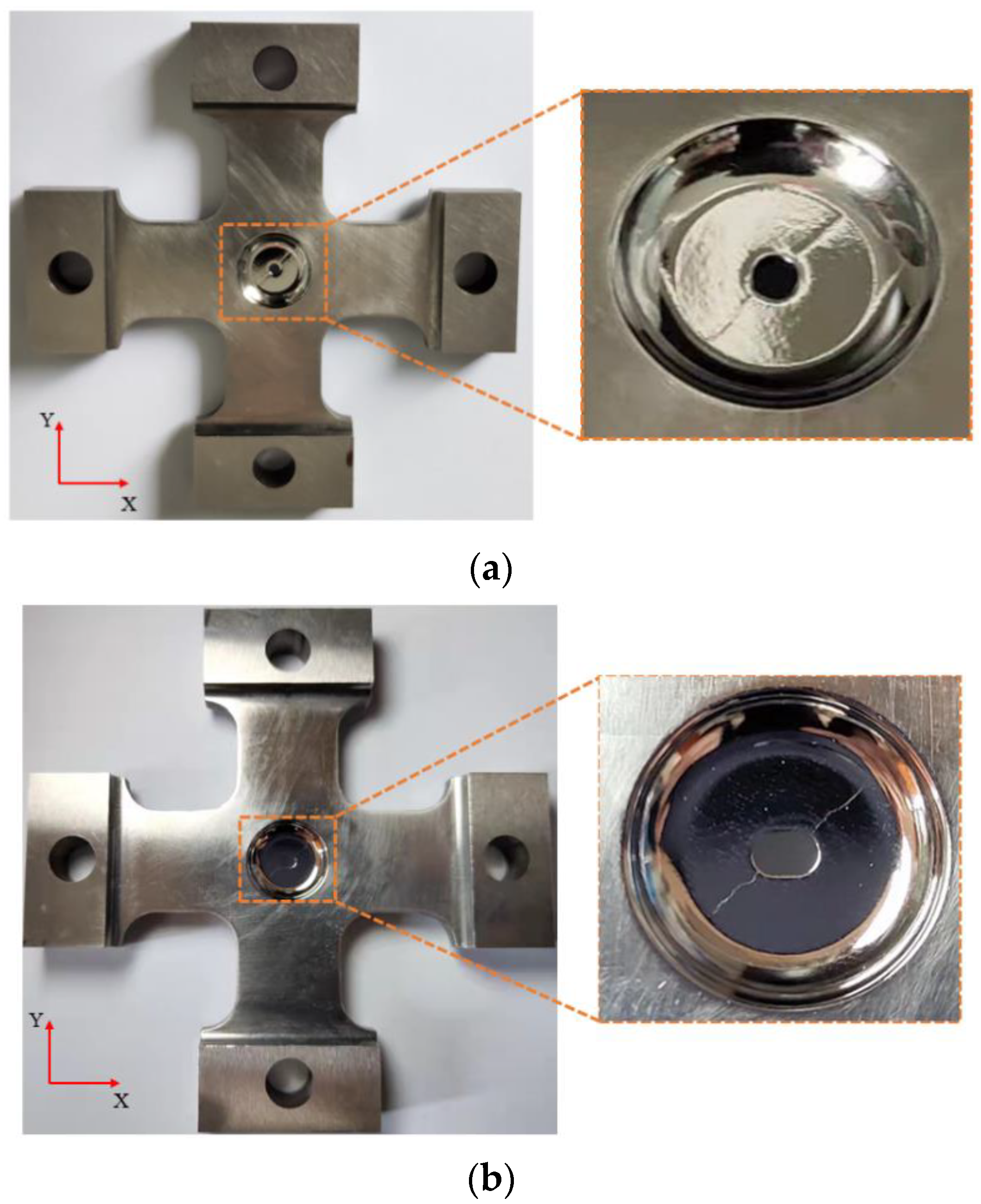
2.2. Preparation of Specimens

Two kinds of cruciform specimens with different shapes of notch in the center area were designed in this paper. These specimens were center-thinned by equal thickness on both sides and had a circular notch or a 0° waist round notch in the central area. The total length of the test piece was 90 mm. The thickness of the central area was 0.8 mm. The four ends of the test piece were 10 mm thick and had circular holes with a diameter of 8 mm. The specific geometry and dimensions of the cruciform specimen are shown in Figure 2.

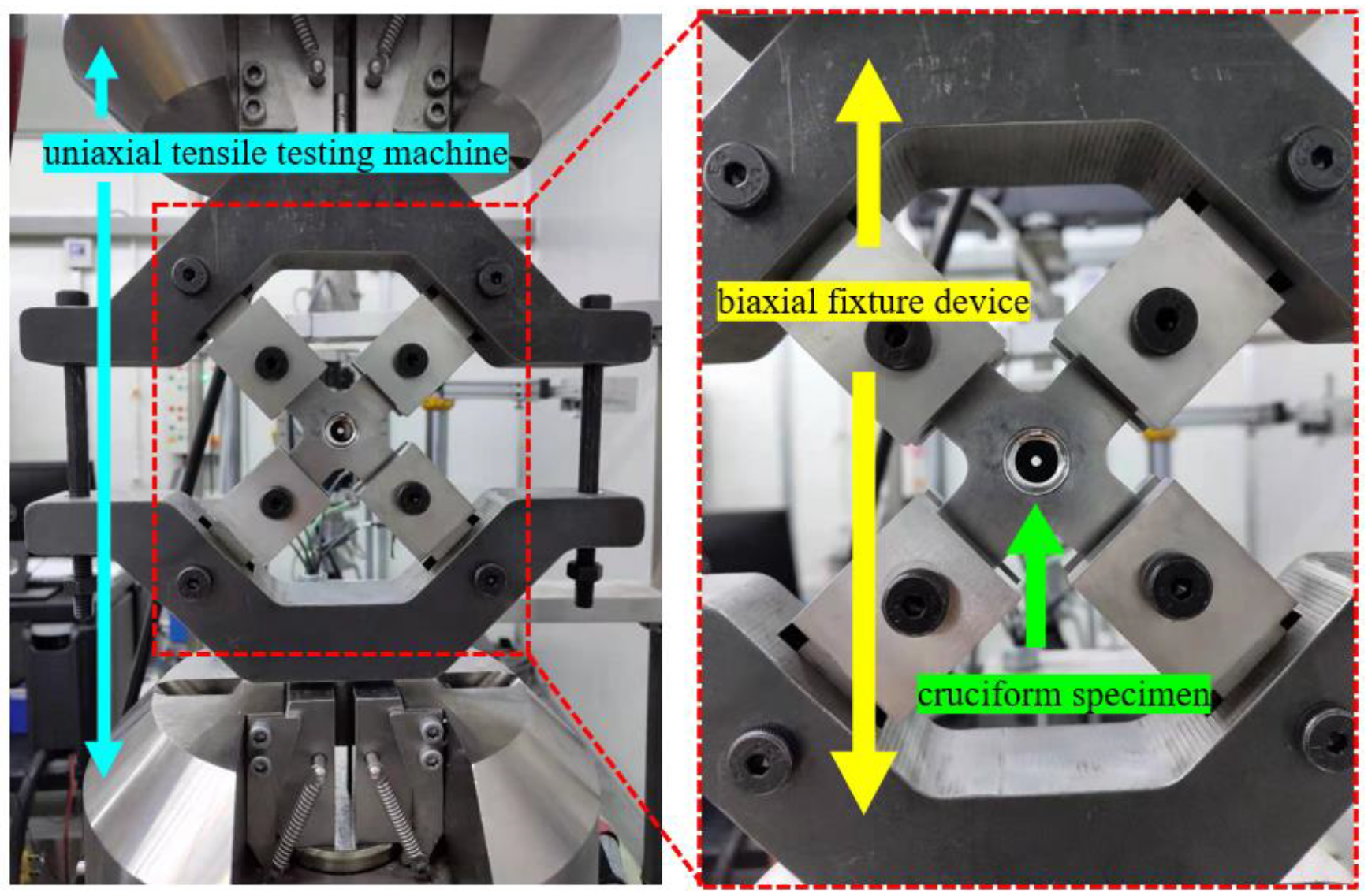
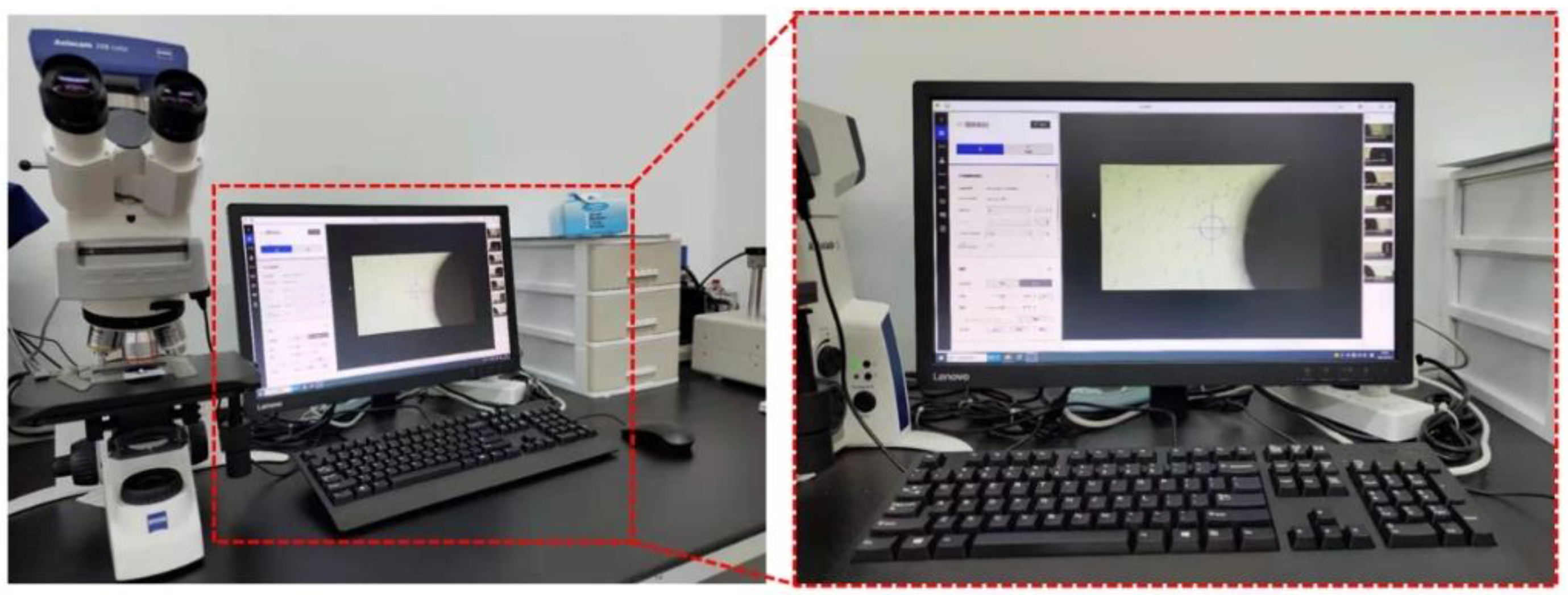
2.3. Fatigue Tests and Replication Method

The biaxial fatigue test was carried out on a uniaxial tensile testing machine in combination with a biaxial fixture device. The test temperature was room temperature. The loading waveform was sine wave. The loading frequency was 10 Hz. The loading amplitudes on both axes were the same. The stress ratio was 0.1. The maximum test load FA was 30 kN and 33 kN, respectively. A total of 9 specimens were tested, of which, 5 specimens were under intermittent loading with the surface replication (SR) method to record the initiation and propagation process of the crack in the central area. The other 4 specimens were under continuous loading without SR method. The detailed biaxial fatigue test conditions are shown in Table 2. The biaxial fatigue test device is shown in Figure 3.
Surface replication is one common crack monitoring method. Compared with other methods, such as the scanning electron microscope method and electric potential method, the SR method has the advantage of repeatable observation of a crack, which is helpful to determine the location of crack initiation and observe the behavior of crack initiation and early growth.
The replication material used in this paper was RepliSet, produced by Struers. This material is a fast-curing binary silicone rubber which can be replicated with a minimum length of 10~20 μm crack. The replication system used for spraying RepliSet is shown in Figure 4. The components of the replication system are manual applicator, RepliSet cylinder box, static mixing nozzle and nozzle head. The replication material is stored in the RepliSet cylinder box; it was sprayed on the specimen through the mixing nozzle and nozzle head. The cylinder box and nozzle are connected to the manual applicator to facilitate the operation.
The procedure of the test using the SR method was as follows [8]. Fatigue load was applied firstly. Then, the static tensile load was applied at 80% of the maximum fatigue load. After the static tensile load, the replication material was sprayed on the central area of the cruciform specimen and then a piece of paper with a size of about 35 × 25 mm2 was pasted on the replication material to facilitate its removal. After the material was completely dry, the paper with the material recording the path of the fatigue crack was removed from the cruciform specimen. The interval of the spraying operations was reasonably selected according to the results of the fatigue test without SR method to ensure that there were about 20 effective copies of each cruciform specimen during its whole fatigue life. As shown in Figure 5, the biaxial fatigue test was terminated when the fatigue crack in the central area of the cruciform specimen extended to the edge of the central area. The microscope shown in Figure 6 successively measured the crack length on each replica from back to front and recorded the relative position of the crack to obtain the biaxial fatigue crack initiation position and the biaxial fatigue crack propagation path. The fatigue fracture morphology of the cruciform specimen was analyzed by scanning electron microscope. The crack projection length obtained from the replica measurement was α, and the definition of crack projection length is shown in Figure 7.

3. Experimental Results and Discussion

3.1. Result of Fatigue Tests

The biaxial fatigue test results are shown in Table 3, where Nf is the full fatigue life of the cruciform specimen. Nini is the fatigue crack initiation life of the cruciform specimen (fatigue crack initiation life is defined as the cycle when the crack is first detected [9]). acrack-ini is the crack length when the first crack is first observed, and Nini/Nf is the ratio of fatigue crack initiation life to full fatigue life.
From the test results, it can be seen that the replication operation had no obvious effect on the biaxial fatigue life, and the fatigue life of the cruciform specimen with a circular notch in the central area was similar to that of the cruciform specimen with a 0° waist hole notch in the central area.
The test data relating to when the second crack appeared on the cruciform specimen are shown in Table 4, where Ncrack-2-ini is the fatigue life of the cruciform specimen when the second crack appeared. Ncrack-2-ini/Nf is the ratio of fatigue life when the second crack appeared to full fatigue life, and acrack-2-ini is the length of the second crack when it was observed for the first time.
From Table 4, it can be seen that the ratio of fatigue life when the second crack appeared to the full fatigue life of specimen 2 was about 52.7%, and the length of the second crack was about 100.7 μm. From Table 4, it can be seen that the ratio of fatigue life when the second crack appeared to the full fatigue life of specimen 7 was about 66.6%, and the length of the second crack was about 64.4 μm. The results of the other specimens were very close. To sum up, the ratio of the fatigue life when the second crack appeared to the full fatigue life was between 52% and 67%, which was similar for specimens with a circular notch in the central area or a 0° waist hole notch in the central area.
The final failure diagram of the cruciform specimen is shown in Figure 8, where (a) is the final failure diagram of the cruciform specimen with a circular notch in the central area, and (b) is the final failure diagram of the cruciform specimen with a 0° waist hole notch in the central area. From Figure 8, it can be seen that two cracks appeared in the central area of the cruciform specimen, and the propagation paths of the two cracks were basically symmetrical.
The crack naming method of the cruciform specimen is shown in Figure 9, where (a) is the crack naming method of the cruciform specimen with a circular notch in the central area, and (b) is the crack naming method of the cruciform specimen with a 0° waist round hole notch in the central area. In these methods, m and n are the specimen number. The black dot is the starting point of the fatigue crack propagation path. The angle between the crack path and the x-axis was measured with the use of ImageJ.
The details of the angle are shown in Table 5. From Table 5, it can be seen that the angle between the crack propagation path and the x-axis on the cruciform specimen with a circular notch in the central area was 42–46°. The angle between the crack propagation path and x-axis on the cruciform specimen with a 0° waist round hole notch in the central area was 40–48°. The starting point of the fatigue crack propagation path is the fatigue crack initiation point, which is also the fatigue dangerous point in terms of the physical mechanism of fatigue damage. The fatigue dangerous point of the cruciform specimen under biaxial equal proportion fatigue load was basically consistent with the position of the maximum principal stress point on the notch edge, which is consistent with Chaves et al.’s conclusions relating to the crack initiation point under torsional and proportional loading [10].
Figure 10 is a replica photo of crack 2-1’s crack initiation and propagation process; Figure 11 is the replica photos of crack 2-2’s crack initiation and propagation process. This group of photos shows the crack initiation and propagation path process of cruciform specimen 2 with a circular notch in the central area under biaxial fatigue load.
Figure 12 is a replica photo of crack 7-1’s crack initiation and propagation process; Figure 13 is the replica photos of crack 7-2’s crack initiation and propagation process. This group of photos shows the crack initiation and propagation path process of cruciform specimen 7 with a 0° waist hole notch in the central area under biaxial fatigue load.
From Figure 10a, it can be seen that crack 2-1 originated from the circular notch. When n = 9000 cycles, crack 2-1 was monitored for the first time, and the crack length was about 193.9 μm. From Figure 10b–h, it can be seen that, after crack 2-1 sprouted from the circular notch, the crack gradually expanded, and the crack path deflected many times during the crack propagation process. From Figure 11a, it can be seen that crack 2-2 originated from the circular notch. When n = 22,200 cycles, crack 2-2 was monitored for the first time. At this time, the crack length of crack 2-2 was about 100 μm. From Figure 11b–h, it can be seen that, after crack 2-2 sprouted from the circular notch, the crack gradually expanded, and the crack path deflected many times during the crack propagation process. From Figure 12a, it can be seen that crack 7-1 originated from the notch of the 0° waist hole. When n = 12,500 cycles, crack 7-1 was monitored for the first time, and the crack length was about 37.4 μm. From Figure 12b–h, it can be seen that, after crack 7-1 initiated from the notch of the 0° waist hole, the crack gradually expanded, and the crack path deflected many times during the crack propagation process. From Figure 13a, it can be seen that crack 7-2 originated from the notch of the 0° waist hole. When n = 23,000 cycles, crack 7-2 was monitored for the first time. At this time, the crack length of crack 7-2 was about 64.4 μm. From Figure 13b–h, it can be seen that, after crack 7-2 sprouted from the notch of the 0° waist hole, the crack gradually expanded, and the crack path deflected many times during the crack propagation process.
To sum up, the crack of the cruciform specimen initiated from the notch. After the crack initiation, the crack gradually expanded, and the crack propagation path deflected many times during the propagation process. There were different orientations between adjacent grains or small defects somewhere on the crack growth path, which may have led to the deflection of the crack growth path, which is consistent with the research on the fatigue crack growth mechanism of nickel-based alloy GH4169 under uniaxial tensile fatigue load by Zhu et al. [11].

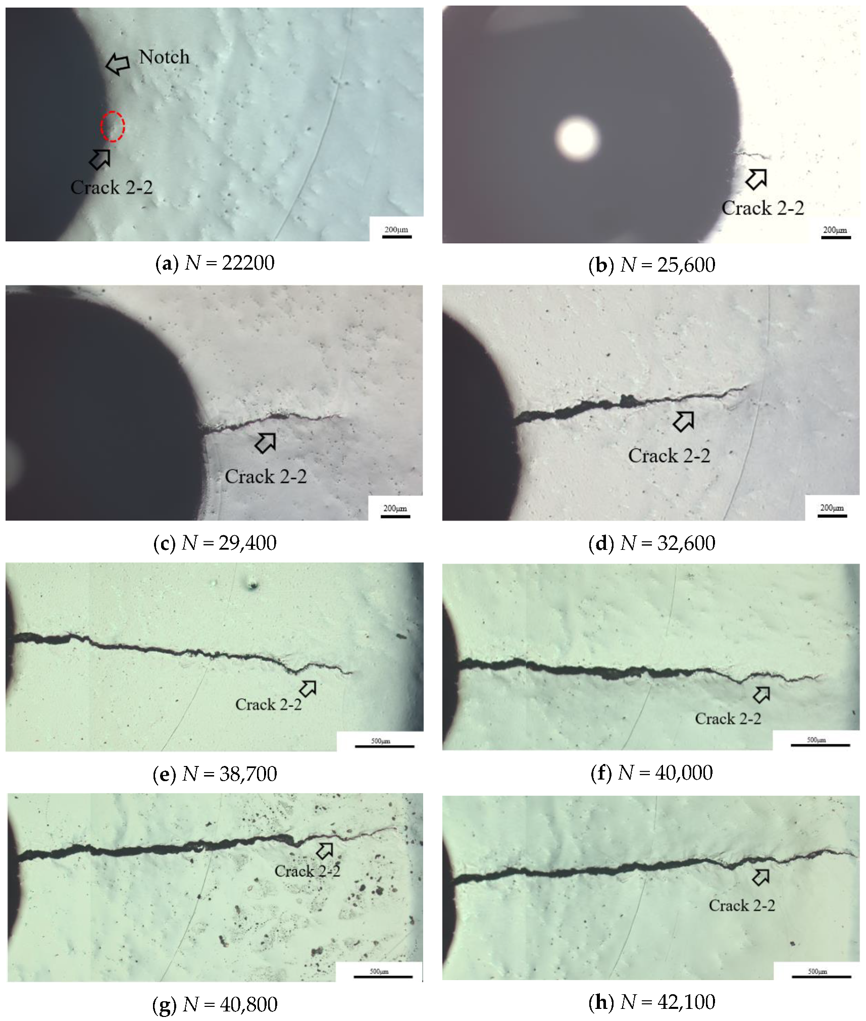
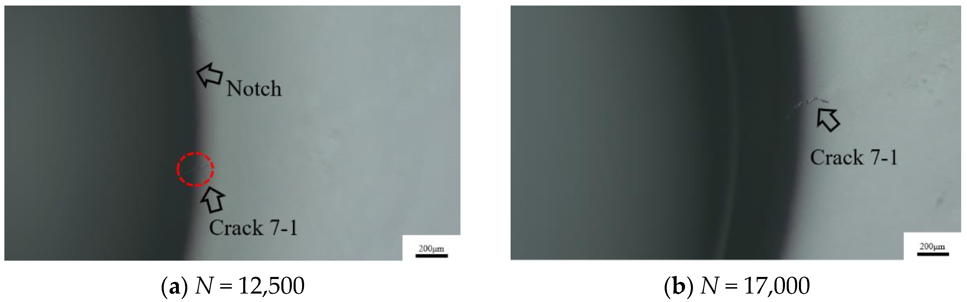
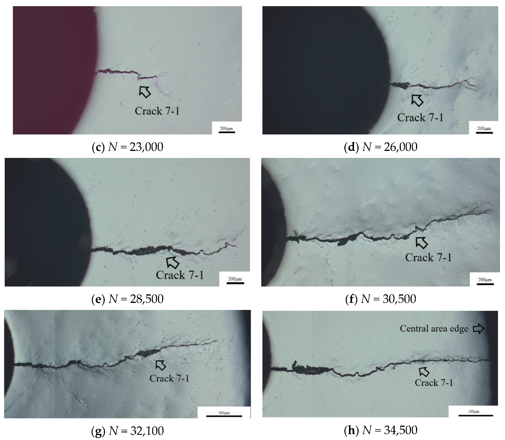
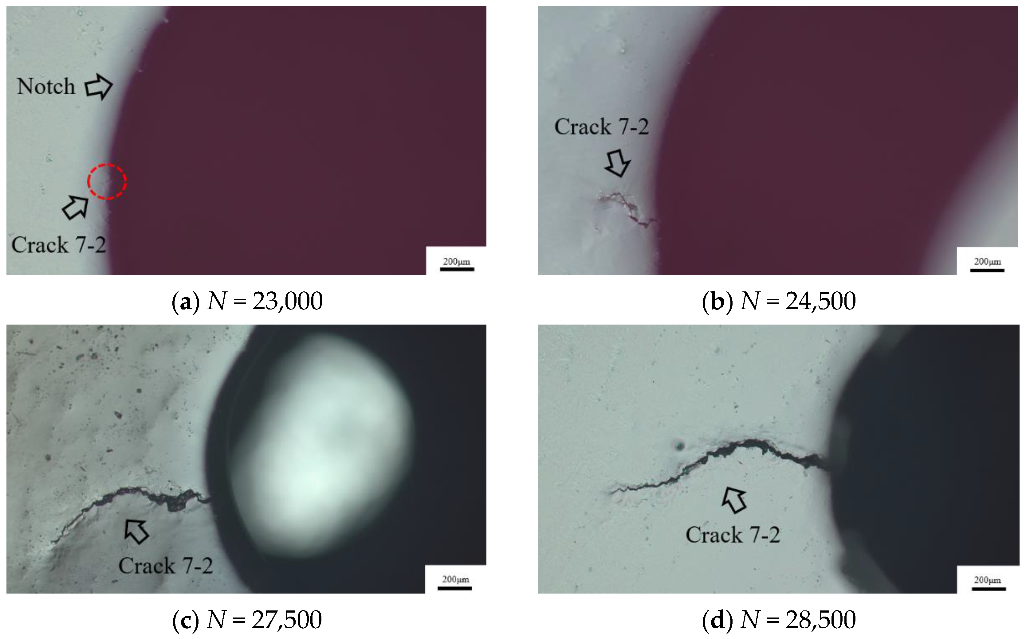
3.2. Biaxial Fatigue Crack Growth Behavior

The variation of the fatigue crack length of the cruciform specimen with a circular notch in the central area is shown in Figure 14, where (a) is the variation diagram of fatigue crack length with the number of cycles, and (b) is the variation diagram of fatigue crack length with cycle ratio. The variation of the crack length of the cruciform specimen with a 0° waist round hole notch in the central area is shown in Figure 15, where (a) is the variation diagram of the fatigue crack length with the number of cycles, and (b) is the variation diagram of the fatigue crack length with cycle ratio.
From Figure 14a and Figure 15a, it can be seen that there is a critical crack length. When the crack length is less than this critical crack length, the crack propagation is very slow. When the crack length exceeds the critical crack length, the crack expands rapidly and leads to the failure of the cruciform specimen. Zhu et al. [12] considered that the critical fatigue crack length of nickel-based alloy GH4169 under uniaxial loading is about 500 μm when studying the small crack initiation and propagation mechanism of nickel-based alloy GH4169 using unilateral notch tensile specimens. Deng et al. [13] considered that the critical fatigue crack length of GH4169 under uniaxial tensile load is about 200 μm when studying the effect of grain size on the small crack initiation and propagation mechanism of nickel-based alloy GH4169. According to Figure 14a and Figure 15a, it can be seen that, under the biaxial fatigue load conditions adopted in this paper, the critical crack length of nickel-based alloy GH4169 under biaxial proportional fatigue load is about 300 μm.
The variation of the biaxial fatigue crack length with cycle ratio (N/Nf) of the cruciform specimen with a circular notch in the central area is shown in Figure 14b, and the variation of the biaxial fatigue crack length with cycle ratio (N/Nf) of the cruciform specimen with a 0° waist circle hole notch in the central area is shown in Figure 15b, where N is the number of fatigue loading cycles, and Nf is the full fatigue life.
From Figure 14b, it can be seen that the variation curves of the two crack lengths of specimen 2 and specimen 3 with the cycle ratio are almost coincident. The cycle times of the first crack of specimen 2 and specimen 3 when it changed from slow growth to rapid growth were about 25% of the whole fatigue life, and the cycle times of the first crack of specimen 5 when it changed from slow growth to rapid growth were about 55% of the whole fatigue life. The difference between them was caused by the magnitude of load. When the load is larger, the crack growth rate in rapid growth is faster, and the rapid growth’s proportion of the whole fatigue life is reduced. The cycle times of the second crack of specimen 2, specimen 3 and specimen 5 when it changed from slow propagation to rapid propagation were about 65% of the whole fatigue life. The difference between the first and second crack of specimen 2 and specimen 3 was because the existing crack could accelerate the growth rate of the second crack in rapid growth. From Figure 15b, it can be seen that the cycle times when the first crack of specimen 7 and specimen 9 changed from slow growth to rapid growth were about 65% of the whole fatigue life, and the cycle times when the second crack of specimen 7 and specimen 9 changed from slow growth to rapid growth were about 70% of the whole fatigue life. This difference was not that big because the shape of a waist circle hole notch is not as sensitive to load and crack sequence as that of a circular notch.
The secant method was used to calculate the crack growth rate:
d a d N = Δ a Δ N = a i + 1 a i N i + 1 N i
where Δa is the difference of crack length, ΔN is the interval of cycle times, ai is the crack length at the number of Ni cycles, which is the average crack length, and a ¯ = a i + 1 + a i / 2 .
The variation of the biaxial fatigue crack growth rate of the cruciform specimen with a circular notch in the central area is shown in Figure 16, where (a) is the change of crack growth rate with crack length, and (b) is the variation of crack growth rate with cycle ratio. The variation of the biaxial fatigue crack growth rate of the cruciform specimen with a waist hole notch in the central area is shown in Figure 17, where (a) is the variation of crack growth rate with crack length, and (b) is the variation of crack growth rate with cycle ratio.
Suresh [14] classified small cracks into microstructure small cracks, mechanical small cracks, physical small cracks and chemical small cracks. The length of physical small cracks is generally less than 0.5–1 mm. In this paper, the size of small cracks is defined as less than 1 mm. From Figure 16a and Figure 17a, it can be seen that the biaxial fatigue crack growth rate of the cruciform specimen fluctuated. In the early stage of small fatigue crack propagation, when the crack length was close to the grain size of the material, the crack propagation was affected by the microstructure properties such as grain orientation and grain boundary morphology. When the angle between the fatigue crack tip and grain boundary was small, the inhibitory effect on the fatigue crack propagation caused by grain boundary was relatively poor. When the angle was large, the inhibitory effect was intense and could even make the crack propagation stop. This is consistent with the conclusion reached by Zhu [11] and Wu [15] when studying the fatigue crack growth behavior of nickel-based alloy GH4169.
The fluctuation of fatigue long crack growth rate is related to the specimen structure, crack closure effect and crack deflection. The central area of the cruciform specimen selected in this paper had equal thickness thinning on both sides, and the thinning transition area of the cruciform specimen had a circular chamfer transition, that is, the thickness of the edge of the central area was larger than the thickness of the central area, which led to the phenomenon that the crack propagation rate decreased during the propagation of the long fatigue crack. The crack closure effect also led to the reduction or retardation of fatigue crack growth rate. Neerukatti et al. [16] found that crack closure reduced the fatigue crack growth rate when studying the fatigue crack growth of an Al7075-T651 cruciform specimen under biaxial tensile load. Elber [17] found through experimental research that, even if the far-field load is a tensile load, the fatigue crack is closed. Under the action of crack closure, the crack surfaces contact in advance, resulting in the arrest of fatigue crack growth.

3.3. Biaxial Fatigue Crack Deflection Behavior

Figure 18 is the relationship between the crack propagation path and the crack propagation rate of cruciform specimen 3 with a circular notch in the central area. The white dot is the crack deflection point, a is the crack length and da/dN is the crack propagation rate. Based on Figure 18a, the decrease in crack growth rate between points 1 and 2, 3 and 4, 5 and 7 and 10 and 13 was related to the deflection of the crack growth path. Based on Figure 18b, the decrease in crack growth rate between points 1 and 2, 3 and 4, 5 and 6, 7 and 8 and 9 and 12 was related to the deflection of the crack growth path. The reduction in crack growth rate under biaxial fatigue loading was related to the deflection of the crack growth path. The effective stress intensity factor of the deflection crack was less than that of a straight crack with the same projection length. When the loading amplitude is the same, the deflection behavior of the fatigue crack path significantly reduces the growth rate of the fatigue crack [18]. The conclusion that the deflection of crack propagation path leads to the reduction of crack propagation rate is consistent with the research results of Bui et al. [19,20] on crack bifurcation and crack deflection.

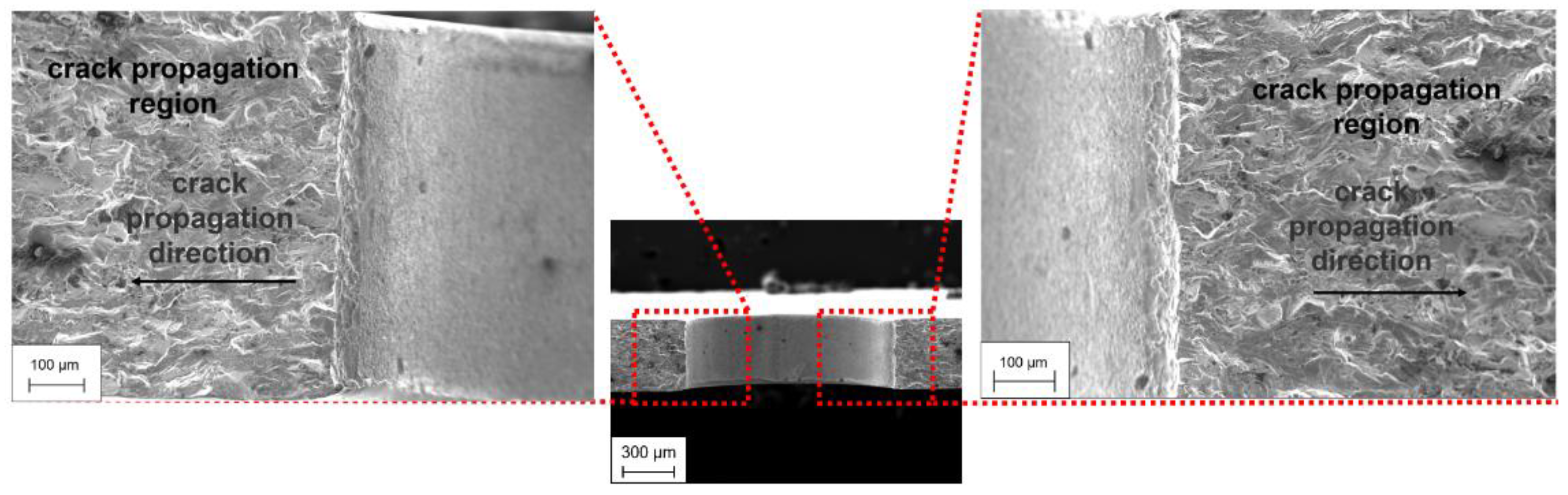
3.4. Fracture Morphology Analysis

The fatigue fracture morphology of the cruciform specimen with a circular notch in the central area was observed and analyzed by scanning electron microscope (SEM). The fatigue fracture morphology is shown in Figure 19, Figure 20, Figure 21 and Figure 22. Figure 19 is the overall morphology near the root of the circular notch in the central area of the cruciform specimen. Figure 20 shows the source area of fatigue crack initiation. From Figure 20, it can be seen that there were many crack initiation sources at the notch root of the cruciform specimen. Fatigue crack propagation can be divided into two stages: the first stage of fatigue crack propagation and the second stage of fatigue crack propagation. Figure 21 shows the characteristics of the first stage of fatigue crack growth. From Figure 21, it can be seen that the first stage of fatigue crack propagation of nickel-based alloy GH4169 presented a parallel, serrated section and a cleavage-like fracture plane. Figure 22 shows the characteristics of the second stage of fatigue crack growth. Fatigue bands can be found in Figure 22, which are perpendicular to the crack propagation direction. It is generally believed that one load cycle corresponds to one fatigue band. Therefore, some scholars [21] measure the fatigue band spacing to calculate the crack growth rate. The results show that this method can also effectively estimate the fatigue crack growth rate.

4. Conclusions

Based on the biaxial fatigue test results and the fatigue crack initiation and propagation process in the central area of the cruciform specimen monitored and recorded by the replica method, the crack propagation path, propagation behavior and deflection behavior of nickel-based alloy GH4169 under biaxial fatigue load were studied, and the fatigue fracture morphology was observed and analyzed by scanning electron microscope. The result can help to develop a fatigue crack life analysis method and damage tolerance design method for key aeroengine components. The conclusions are as follows:
(1) The crack of the cruciform specimen initiated from the notch. In the process of propagation, the crack propagation path deflected many times. In the early stage of small crack propagation, the crack propagation rate fluctuated greatly due to the influence of microstructure properties such as grain orientation and grain boundary morphology. At the stage of long crack growth, the crack growth rate fluctuated due to the specimen structure and crack deflection. The deflection of the crack propagation path reduced the crack propagation rate;
(2) Under biaxial proportional fatigue loading, the critical crack length of nickel-based alloy GH4169 during crack propagation is about 300 μm. When the crack length is less than 300 μm, the crack grows slowly, and when the crack length is larger than 300 μm, the crack propagates rapidly;
(3) There were many crack initiation sources at the notch root of the cruciform specimen. The propagation of a biaxial fatigue crack is divided into the first stage and the second stage. The first stage of fatigue crack propagation presents a parallel, serrated section and cleavage-like fracture small plane; the second stage of fatigue crack propagation presents fatigue bands, and the fatigue bands are perpendicular to the crack propagation direction;
(4) The method of combining a uniaxial tensile testing machine and biaxial fixture device has the advantage of low cost and easy access.

Author Contributions

Conceptualization, Z.W.; methodology, L.F.; software, H.L.; validation, Y.P. and H.L.; formal analysis, S.W. and Y.P.; investigation, S.W.; resources, H.L. and L.F.; data curation, S.W.; writing—original draft preparation, Y.P. and S.W.; writing—review and editing, Y.P.; visualization, S.W. and Y.P.; supervision, L.F.; project administration, Z.W.; funding acquisition, Z.W. All authors have read and agreed to the published version of the manuscript.

Funding

This research was funded by the Major National Science and Technology Project grant number J2019-IV-0008-0076.

Data Availability Statement

Data not available due to ethical restrictions.

Conflicts of Interest

The authors declare that they have no conflict of interest.

References

  1. Wolf, C.H.; Henkel, S.; Burgold, A.; Qiu, Y.X.; Kuna, M.; Biermann, H. Investigation of fatigue crack growth under in-phase loading as well as phase-shifted loading using cruciform specimens. Int. J. Fatigue 2019, 124, 595–617. [Google Scholar] [CrossRef]
  2. Meng, Y.X.; Gao, H.; Yan, Y.Z.; Gao, L.L. Effects of phase difference and stress ratio on biaxial tension–tension fatigue crack propagation behavior of rolled ZK60 magnesium alloy. Mater. Today Commun. 2020, 24, 101159. [Google Scholar] [CrossRef]
  3. Abecassis, M.; Köster, A.; Esin, V.A.; Chiaruttini, V.; Maurel, V. Crack Growth Behavior in Dissimilar Welded Ti Based Alloys under Biaxial Fatigue Loading. Int. J. Fatigue 2018, 118, 209–224. [Google Scholar] [CrossRef] [Green Version]
  4. Misak, H.E.; Perel, V.Y.; Sabelkin, V.; Mall, S. Biaxial tension–tension fatigue crack growth behavior of 2024-T3 under ambient air and salt water environments. Eng. Fract. Mech. 2014, 118, 83–97. [Google Scholar] [CrossRef]
  5. Limin, S.; Chao, Z. Experimental Research on Turning of Superalloy GH4169 under High Pressure Cooling Condition. Integr. Ferroelectr. 2020, 207, 75–85. [Google Scholar] [CrossRef]
  6. Xu, R.F.; Zhou, Y.X.; Li, X.; Yang, S.L.; Han, K.N.; Wang, S.J. The Effect of Milling Cooling Conditions on the Surface Integrity and Fatigue Behavior of the GH4169 Superalloy. Metals 2019, 9, 1179. [Google Scholar] [CrossRef] [Green Version]
  7. Wu, D.X.; Zhang, D.H.; Yao, C.F. Effect of Turning and Surface Polishing Treatments on Surface Integrity and Fatigue Performance of Nickel-Based Alloy GH4169. Metals 2018, 8, 549. [Google Scholar] [CrossRef] [Green Version]
  8. Zhu, L.; Wu, Z.R.; Hu, X.T.; Song, Y.D. Small Fatigue Crack Growth Behavior of Nickel-Based Alloy GH4169. J. Aeronaut. Power 2017, 32, 1984–1991. Available online: https://www.webofscience.com/wos/alldb/full-record/CSCD:6079438 (accessed on 23 August 2017).
  9. Zhu, L.; Hu, X.T.; Jiang, R.; Song, Y.D.; Qu, S.D. An investigation of small fatigue crack behavior in titanium alloy TC4 under different stress levels. Proc. Inst. Mech. Eng. Part G J. Aerosp. Eng. 2019, 233, 5567–5578. [Google Scholar] [CrossRef]
  10. Chaves, V.; Beretta, G.; Balbín, J.A.; Navarro, A. Fatigue life and crack growth direction in 7075-T6 aluminium alloy specimens with a circular hole under biaxial loading. Int. J. Fatigue 2019, 125, 222–236. [Google Scholar] [CrossRef]
  11. Zhu, L.; Wu, Z.R.; Hu, X.T.; Song, Y.D. Investigation of small fatigue crack initiation and growth behaviour of nickel base superalloy GH4169. Fatigue Fract. Eng. Mater. Struct. 2016, 39, 1150–1160. [Google Scholar] [CrossRef]
  12. Zhu, L.; Wu, Z.; Hu, X.T.; Song, Y.D. Comparative study of small crack growth behavior between specimens with and without machining-induced residual stress of alloy GH4169. J. Mech. Sci. Technol. 2018, 32, 5251–5261. [Google Scholar] [CrossRef]
  13. Deng, G.J.; Tu, S.T.; Zhang, X.C.; Wang, Q.Q.; Qin, C.H. Grain size effect on the small fatigue crack initiation and growth mechanisms of nickel-based superalloy GH4169. Eng. Fract. Mech. 2015, 134, 433–450. [Google Scholar] [CrossRef]
  14. Suresh, S. Crack deflection: Implications for the growth of long and short fatigue cracks. Metall. Trans. A 1983, 14, 2375–2385. [Google Scholar] [CrossRef]
  15. Wu, Z.R.; Liu, F.L.; Li, X.; Fang, L.; Song, Y.D. Multistage fatigue modeling of single-edge-notch tension specimens for Ni-based superalloy GH4169. Adv. Mech. Eng. 2017, 9, 168781401772994. [Google Scholar] [CrossRef]
  16. Neerukatti, R.K.; Datta, S.; Chattopadhyay, A.; Iyyer, N.; Phan, N. Fatigue crack propagation under in-phase and out-of-phase biaxial loading. Fatigue Fract. Eng. Mater. Struct. 2018, 41, 387–399. [Google Scholar] [CrossRef]
  17. Elber, W. The Significance of Fatigue Crack Closure; ASTM International: West Conshohocken, PA, USA, 1971; p. 486. [Google Scholar] [CrossRef]
  18. Wang, Y.; Huang, H.; Gao, K.Y.; Wen, S.P.; Zhang, P.P.; Nie, Z.R. Fatigue Fracture Behavior of Cold Rolled 5E06 and 5E83 Aluminum Alloy Plate. Chin. J. Rare Met. 2011, 35, 791–798. Available online: https://www.webofscience.com/wos/alldb/full-record/CSCD:4369885 (accessed on 1 June 2011).
  19. Bui, T.P.; Miyashita, Y.; Mutoh, Y.; Morikage, Y.; Tagawa, T.; Handa, T.; Otsuka, Y. Fatigue crack deflection and branching behavior of low carbon steel under mechanically large grain condition. Int. J. Fatigue 2021, 148, 106217. [Google Scholar] [CrossRef]
  20. Bui, T.P.; Miyashita, Y.; Morikage, Y.; Tagawa, T.; Handa, T.; Mutoh, Y.; Otsuka, Y. Contributions of Grain Size and Crystal Orientation to Fatigue Crack Deflection and Branching Behavior in Low Carbon Steel Plates. ISIJ Int. 2020, 61, 424–433. [Google Scholar] [CrossRef]
  21. Caton, M.J.; Jhon, R.; Porter, W.J.; Burba, M.E. Stress ratio effects on small fatigue crack growth in Ti-6Al-4V. Int. J. Fatigue 2011, 38, 36–45. [Google Scholar] [CrossRef]
Figure 1. Microstructural result of GH4169.
Metals 13 00588 g001
Figure 2. Geometry and dimensions of cruciform specimen (mm). (a) Cruciform specimen with circular notch in the central area. (b) Cruciform specimen with 0° waist circle hole notch in the central area.
Metals 13 00588 g002
Figure 3. Biaxial fatigue test device.
Metals 13 00588 g003
Figure 4. Replication system for surface replication.
Metals 13 00588 g004
Figure 5. Criterion of crack condition at termination of biaxial fatigue test.
Metals 13 00588 g005
Figure 6. Microscope for observing fatigue crack remodeling.
Metals 13 00588 g006
Figure 7. Crack projection length definition. (a) Crack projection length of circular notch specimen in central region. (b) Crack projection length of 0° waist circular hole notch specimen in central region.
Metals 13 00588 g007
Figure 8. Final failure diagram of cruciform specimen. (a) Cruciform specimen with circular notch in the central area. (b) Cruciform specimen with 0° waist circle hole notch in the central area.
Metals 13 00588 g008
Figure 9. Crack naming method of cruciform specimen. (a) Cruciform specimen with circular notch in the central area. (b) Cruciform specimen with 0° waist circle hole notch in the central area.
Metals 13 00588 g009
Figure 10. Crack 2-1 initiation and propagation process.
Metals 13 00588 g010
Figure 11. Crack 2-2 initiation and propagation process.
Metals 13 00588 g011
Figure 12. Crack 7-1 initiation and propagation process.
Metals 13 00588 g012aMetals 13 00588 g012b
Figure 13. Crack 7-2 initiation and propagation process.
Metals 13 00588 g013aMetals 13 00588 g013b
Figure 14. Variation of crack length of cruciform specimen with circular notch in the central area. (a) Variation of crack length with cycle number. (b) Variation of crack length with cycle ratio.
Metals 13 00588 g014
Figure 15. Variation of crack length of cruciform specimen with 0° waist circle hole notch in the central area. (a) Variation of crack length with cycle number. (b) Variation of crack length with cycle ratio.
Metals 13 00588 g015
Figure 16. Variation of crack growth rate of cruciform specimen with circular notch in the central area. (a) Variation of crack growth rate with crack length. (b) Variation of crack growth rate with cycle ratio.
Metals 13 00588 g016
Figure 17. Variation of crack growth rate of cruciform specimen with 0° waist hole notch in the central area. (a) Variation of crack growth rate with crack length. (b) Variation of crack growth rate with cycle ratio.
Metals 13 00588 g017
Figure 18. Relationship between crack growth path and crack growth rate.
Metals 13 00588 g018
Figure 19. Overall morphology near circular notch.
Metals 13 00588 g019
Figure 20. Fatigue crack initiation source region.
Metals 13 00588 g020
Figure 21. Characteristics of the first stage of fatigue crack growth.
Metals 13 00588 g021
Figure 22. Characteristics of the second stage of fatigue crack growth.
Metals 13 00588 g022
Table 1. Main chemical composition of nickel-based alloy GH4169.
ElementNbMoTiCrFeNi
Wt/%5.673.841.4019.1417.2052.76
Table 2. Test conditions of cruciform specimen.
SpecimenNotch ShapeStress RadioFA, max (kN)Test Condition
1circular notch0.130Non-SR
2circular notch0.130SR
3circular notch0.130SR
4circular notch0.133Non-SR
5circular notch0.133SR
6waist round notch0.130Non-SR
7waist round notch0.130SR
8waist round notch0.133Non-SR
9waist round notch0.133SR
Table 3. Biaxial fatigue test results of cruciform specimens.
SpecimenNf (Cycles)Nini (Cycles)acrack-ini (μm)Nini/NfNumber of Cracks
137,784///2
242,1009000193.921.38%2
334,500770019322.32%2
431,500///2
523,700700042.429.53%2
634,000///2
734,50012,50037.436.23%2
821,500///2
924,900850058.534.14%2
Table 4. Test data of cruciform specimen with the second crack.
Specimen NumberNf
(Cycles)
Ncrack-2-ini
(Cycles)
Ncrack-2-ini/Nfacrack-2-ini
(μm)
242,10022,20052.7%100.7
334,50018,50053.6%100.6
523,70012,80054.0%26.70
734,50023,00066.6%64.4
924,90013,00052.2%36.3
Table 5. Angle between crack propagation path and x-axis in the cruciform specimen.
Specimen NumberCrack NumberAngle
1Crack 1-145.2°
Crack 1-244.3°
2Crack 2-145.3°
Crack 2-243.3°
3Crack 3-143.2°
Crack 3-245.5°
4Crack 4-144.1°
Crack 4-242.3°
5Crack 5-143.5°
Crack 5-244.3°
6Crack 6-140.7°
Crack 6-242.9°
7Crack 7-140.5°
Crack 7-241.4°
8Crack 8-144.4°
Crack 8-247.5°
9Crack 9-140.1°
Crack 9-242.6°
Disclaimer/Publisher’s Note: The statements, opinions and data contained in all publications are solely those of the individual author(s) and contributor(s) and not of MDPI and/or the editor(s). MDPI and/or the editor(s) disclaim responsibility for any injury to people or property resulting from any ideas, methods, instructions or products referred to in the content.

