Article

Research on Simulation and Optimization of Traveling Induction Heating Process for Welding Deformation Rectification in High Strength Steel Sheet

1
School of Naval Architecture Engineering, Dalian University of Technology, Dalian 116024, China
2
State Key Laboratory of Structural Analysis, Optimization and CAE Software for Industrial Equipment, Dalian 116024, China
3
Collaborative Innovation Center for Advanced Ship and Deep-Sea Exploration, Shanghai 200240, China
*
Author to whom correspondence should be addressed.
Metals 2023, 13(2), 425; https://doi.org/10.3390/met13020425
Submission received: 3 January 2023 / Revised: 6 February 2023 / Accepted: 13 February 2023 / Published: 18 February 2023
(This article belongs to the Special Issue Numerical Simulation of Metals Welding Process)

Abstract

:
To observe the evolution mechanism of physical fields in the welding deformation rectification process by a traveling induction heating, research on simulation models of welding—induction heating continuous process were carried out. High-strength steel plates were selected for welding deformation experiment and induction heating rectification experiment in turn, and the stress field and strain field distribution after various processes were measured and recorded. Then, according to the construction process, an integrated model of welding-induction heating based on moving mesh method was analyzed and established by Ansys FE software, moreover, another progressive integrated model established based on the re-defined element attributes method was studied, and the calculation accuracy of these models were compared as well as the characteristics were analyzed. The research results show that these two integrated models can accurately reflect the evolution law of each physical field in the process of welding and induction heating, and the re-defined element attributes method is more suitable for the research of welding deformation and induction heating rectification process.

1. Introduction

Welding deformation rectification technology has always been a difficult point in the research of ship construction technology [1,2]. At present, in the shipyard, the flame correction method is the main mean of welding deformation rectification, which is inefficient, backward, and depends on artificial experience, so it is inapplicable to adapt to the rapid, intelligent and efficient development of shipbuilding technology [3]. With the continuous development of induction heating technology, the research on using induction heating process to correct welding deformation has attracted extensive attention [4]. However, in actual research, welding process and induction heating process are both high temperature heat treatment processes, it is laborious to observe the temperature, stress and strain field in real time and accurately during processing [5]. The research methods of deformation rectification by induction heating mainly rely on experimental means, the stress and strain data at local positions on the structure sur-face are measured after metal cooling, so as to the influence of welding and induction heating factors on the structure can be speculated [3,6]. However, there are many defects in the experimental method, these negative effects lead to few research achievements in the field of welding deformation rectification by induction heating [7].
With the progress of computer simulation technology, numerical analysis technology can help design and research welding process and induction heating process economically and efficiently [8,9]. The current research on welding simulation mainly focuses on the distribution of welding pool, the evolution of physical fields, and the shape of structural parts, etc. Through the reasonable application of element birth and death technique, boundary conditions and constraints, the whole process of welding construction can be accurately simulated [10]. Moreover, the evolution of welding quality and structural strength of welded joints at different temperatures can also be accurately and efficiently simulated by simulation methods [11,12]. In the simulation of induction heating, the electromagnetic-thermal-structure coupling is a relatively accurate simulation method that conforms to the actual physical transformation process. Through the interaction of electromagnetic field, temperature field and deformation field, a reasonable calculation result of induction heating can be obtained [13,14]. Nevertheless, when it comes to the simulation model of welding deformation rectification process using induction heating method, the physical field of the welding process and the physical field of the induction heating process must be closely connected, this situation makes it extremely catastrophic to study the simulation model of integral welding-induction heating process [14,15].
The current models for the process of welding deformation rectification by induction heating mainly focus on the induction heating stage [13,14]. Generally, the welding deformation and residual stress are extremely simplified, partial concentrated residual stress is extracted as initial load, and then loaded into the calculation of induction process. Even in some studies, the influence of welding process is completely ignored and only the induction heating process is directly simulated for the structure [16,17]. These methods can approximate the results of some physical fields, but the calculation process is not convincing when used to simulate welding deformation correction [18]. Based on the above factors, when studying the simulation model of welding deformation rectification by induction heating process, it is necessary to precise simulate the welding process, when all the stress fields and strain fields of welding are obtained, then the simulation research of induction heating process is conducted on this basis.
According to the above analysis, in order to accurately simulate the continuous process of welding-induction heating, the temperature field and strain field in the welding process should be connected with the electromagnetic field, temperature field and strain field in the induction heating process [16]. For instance, when the deformation rectification process of common fillet-welded joints in the hull structure is taken as the research object, after the simulation of the fillet welding process, the welding structure field cannot be directly loaded on the electromagnetic field, which makes it unworkable to simulate the subsequent induction heating process. However, considering that the deformation of the back area of the weld seam in the welding de-formation field is terribly small, and electromagnetic induction heating has the characteristics of heat source concentration and skin effect, it can be considered that the position of the induction heating area on the back of the base plate relative to the in-duction coil is unchanged before and after the welding deformation [19,20]. Therefore, an idea is put forward in the experimental simulation process, the sequence of thermal-structure coupling in welding and electromagnetic-thermal-structure coupling in induction heating can be changed into the sequence of welding thermal, induction electromagnetic, induction thermal and welding structure, induction structure coupling, furthermore, the flexible application of multi physical field conversion method and element birth and death technique makes its realization possible [21]. In this simulation calculation, the structure mode needs to be loaded the welding thermal load first, after welding process calculation, the model is loaded with induction heat load, and the process of induction heating rectification is calculated on the basis of welding deformation, then the simulation of continuous welding-induction heating process is implemented.
In the process of rectifying welding deformation by induction heating, the coil is heated by moving. At present, the simulation of mobile induction heating methods mainly includes the re-meshing technology and the moving mesh method [22,23]. The re-meshing technology needs to redraw the meshes of the coil and air area, and new conditions are imposed, after each induction heating calculation. This method requires high computer configuration, and requires a lot of time for each step of calculation [24]. The moving mesh method needs to divide a flat air area grid between the induction coil and the metal parts, after each calculation, the coil and the nearby air area will be moved, and then connected with the air area near the metal in the form of a constraint equation [25]. However, this method demands that the shape of the coil and the metal parts must be flat and regular [26,27]. In addition, the size and quality of the air unit will also affect the calculation accuracy of the constraint equation.
Based on the above analysis, on the basis of the integrated simulation model of welding-induction heating, the re-meshing technology in the process of moving induction heating is optimized to re-defined element attributes method. When modeling, the area of the coil moving path is divided into unified units. Then, when conducting in-duction heating calculation, only the elements in the coil are re-customized in different periods, and the effect of coil movement over time is simulated by calculating the load steps in turn. The established model can not only simulate the whole welding-induction process, but also overcome the influence of redefining the constraint equation, and then an accurate simulation model of travelling induction heating for welding deformation rectification can be established.
Generally, steel with yield strength greater than 235 MPa is regarded as high-strength steel in the shipyard, and Q345 steel plate is one of the most common steel plates for ship. In this study, Q345 steel plates of different thicknesses were selected to conduct fillet welding and induction heating rectification experiments in turn, and the structural deformation morphology and stress distribution state after processing were measured and recorded. Then, according to the experimental processing procedure, the holistic model of welding-induction heating, based on the moving mesh method and re-defined element attributes method, is established, respectively, by using the Ansys finite element software. Finally, the accuracy of each model was discussed by comparing the experimental measurement data, the characteristics of each model were analyzed and the reliability of the models is determined.

2. Experimental Procedure

2.1. Experimental Methodology

When the induction heating method is studied and applied to correct the welding deformation, the shape deformation and stress distribution in the structure generated by the welding process should be considered first, and then the induction heating process is carried out on this basis, the structural deformation and stress distribution of the welded joint after the induction heating can be analyzed. By comparing the deformation value and stress distribution after welding and induction heating, the correction effect of induction heating process on welding deformation can be judged.
Based on the above factors, in the design of the experimental process, first of all, Q345 high-strength steel plate, which is common in shipbuilding materials, was selected as the research material, and the most popular T-shaped welded joint was selected as the research structure. Then, according to the preset processing parameters, steel plates of the same specification were selected in turn for welding experiments and induction heating experiments, and the evolution rules of stress and strain in welded joints were discussed and analyzed. Finally, according to the experimental process, the corresponding simulation model could be established, and the reliability and accuracy of the simulation model could be verified based on the measured data.

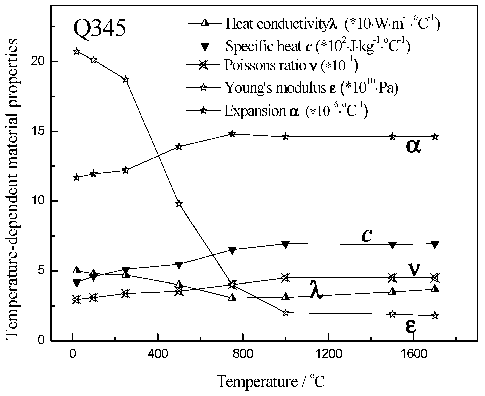
2.2. Experimental Materials

The Q345 grade high strength steel was selected as the experimental material, the chemical components are listed in the following Table 1 and the material properties are shown in the Table 2.

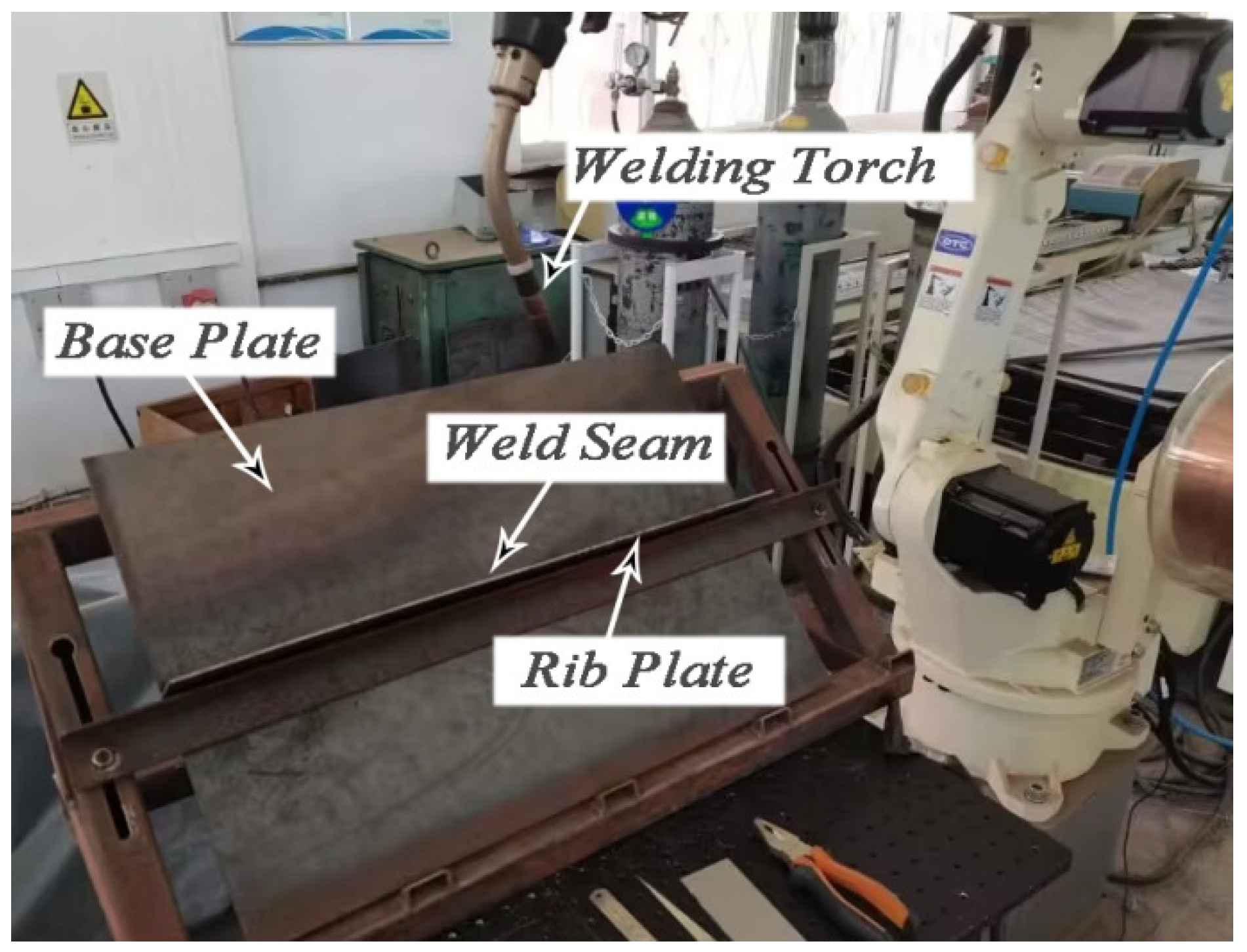
2.3. Welding Experiment

2.3.1. Welding Process Method

According to the order of ship construction, steel plates with different thicknesses were selected for fillet welding experiment at first. In fillet welded joint, the length of the base plate was 600 mm, the width was 400 mm, and the thickness of base plate was 3 and 5 mm, respectively; the length and width of rib plate was 600 mm and 60 mm, respectively, and the thickness was the same as that of base plate. The welding process is shown in Figure 1.
In this study, the pulse MIG/MAG DC welding power source controlled by an OTC FD-V6 welding robot was applied to perform MAG welding, the mixed gas of CO2 (20%) and Ar (80%) was used for welding shielding gas. Prior to welding, tack welding was performed at both ends and in the middle of the rib plate. To obtain stable and uniform deformation, during welding, the base plate positions on both sides of the weld were clamped by the fixture, the central area of base plate and rib plate were fixed on a corner plate by clamps, and the welding seams on both sides of the rib plate should move in the same direction. After welding, when the test piece was cooled to room temperature (about 20 °C), welding deformation and residual stress distribution of the fillet welded joint were measured.
The deformation of fillet welded joint is mainly concentrated on both sides of the base plate, which is also the main position affecting the construction accuracy, then vernier caliper was used to measure the angular deformation (z-direction) on both sides of the base plate, the diagram of deformation position measurement is shown in Figure 2. In Figure 2, six coordinate points (P1 to P6) were selected at the edge of the base plate as the deformation measurement positions, and the deformation amount was the height h of the vertical plate warping. The x direction was set as transverse, the y direction was set as longitudinal direction, and the z direction was set to vertical. To ensure the accuracy of experimental data, steel plates of different thicknesses were selected for welding experiments. The welding process parameters and the specific post-weld distortion data of samples are shown in Table 3.

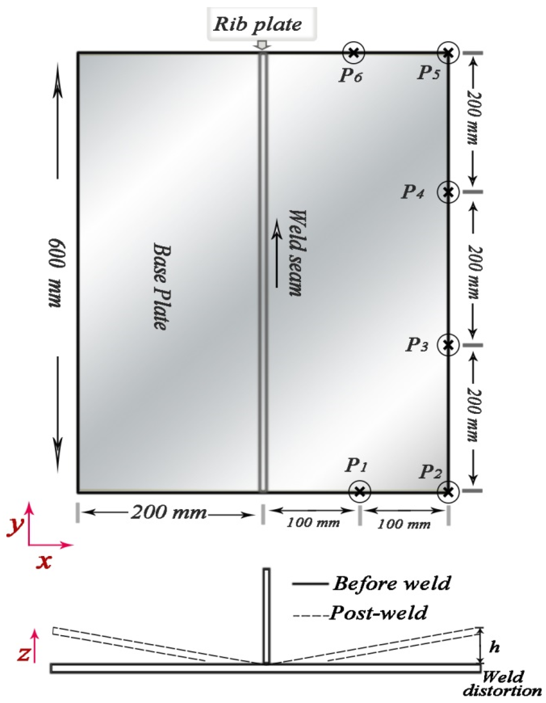
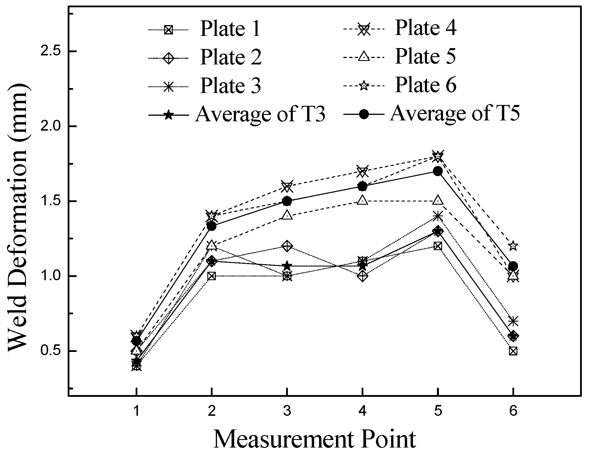
2.3.2. Welding Deformation Results

After the welding experiment, the deformation data in z-axis direction of each measuring point in Figure 2 were measured in turn, and then the deformation amount h of different plate thicknesses were obtained, the experimental average deformation results are shown in Figure 3.
The data in Figure 2 shows that due to many constraints, the deformation caused by welding was small, and the deformation was obvious when the plate was thick. The maximum deformation caused by welding was located at the edge of the plate. There was warping deformation at the edge of the bottom plate, and the overall deformation law was relatively uniform.

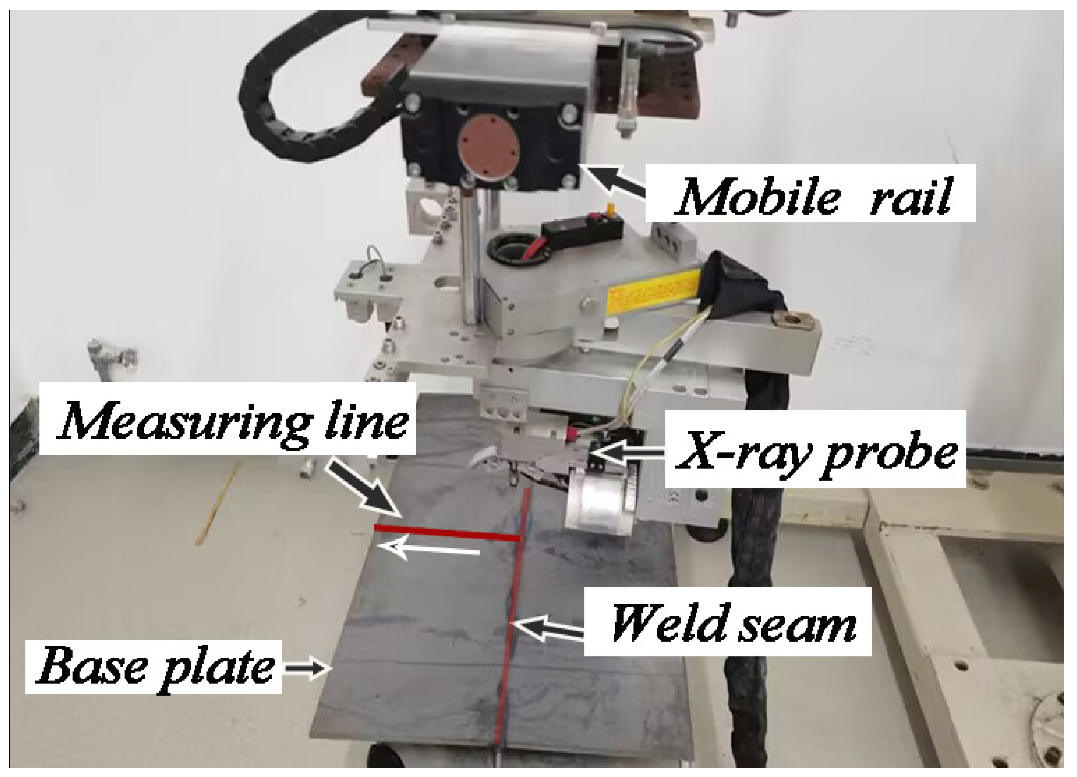
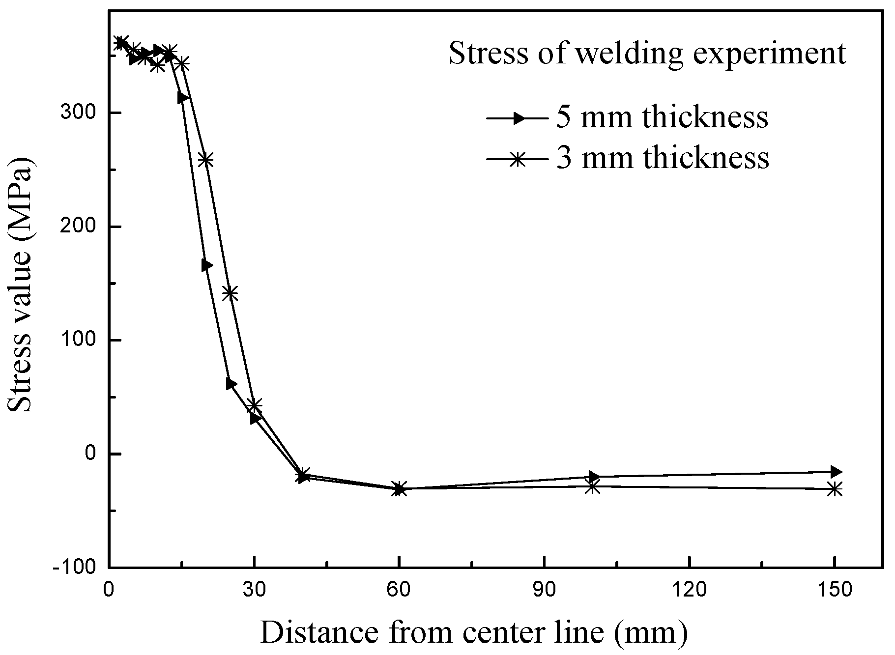
2.3.3. Welding Residual Stress Results

In the welding residual stress field, a significant characteristic of stress distribution can be found that the longitudinal residual stress (along the weld direction; y-direction) is obviously greater than the transverse residual stress (perpendicular to weld direction; x-direction), so the longitudinal residual stress was selected as the research and analysis target in this paper. The residual stress was measured by an Xstress 3000 X-ray diffraction stress meter manufactured by StresstechOy in laukaa, Finland. The high stress area is mainly distributed near the weld seam, so the measurement points near the weld area were relatively dense, while the measurement points far away from the weld area were relatively sparse. For the welding of thin plates, the longitudinal residual stress distribution on the front and back of the bottom plate presents a similar distribution trend. To facilitate the stress measurement, the perpendicular bisector of the weld line on the back of the base plate was selected as the stress measurement line. In this paper, the steel plates of No. 3 and No. 6 were selected as the stress measurement specimens of 3 mm and 5 mm thick steel plates, respectively. The schematic diagram of residual stress measurement is shown in Figure 4, and the average value of longitudinal residual stress (y-direction) measurement data after welding is shown in Figure 5.
The measurement results show that the longitudinal residual stress had a similar distribution law after welding experiments on two plates with different thicknesses, and the larger stress concentration was distributed within 30 mm of the weld line. When the measurement points were far away from the weld line, the stress value would rapidly reduce, and then tend to be stable. At this time, the stress would also change from tensile stress to smaller compressive stress.

2.4. Induction Heating Experiment

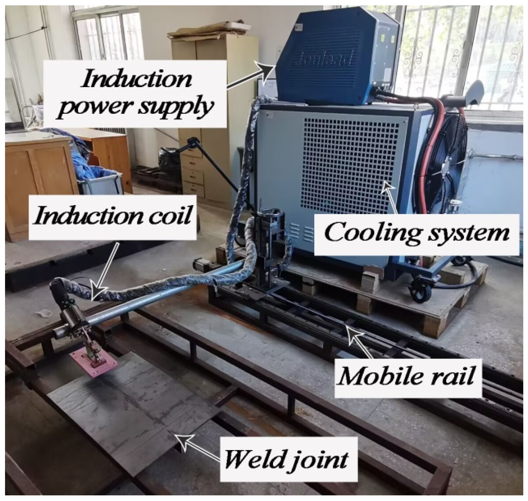
2.4.1. Induction Heating Process Method

After the welding experiment, the mobile induction heating experiment was carried out on the back of the base plate. The heating line coincided with the position of the rib plate, and the direction was consistent with the welding direction. The induction heating experiment was carried out by customized JM-25 electromagnetic induction heating source. The induction coil was fixed on a clamping arm which could move at a controlled speed. The length of the coil was 100 mm, and the height and width were 10 mm.
During induction heating, the coil should be kept 3 mm away from the heating surface, and the coil heating line should be on the centerline of the back of the base plate. By presetting different induction current, frequency and coil movement rate, induction heating process on fillet welded joints was conducted. The induction heating experiment is shown in Figure 6.

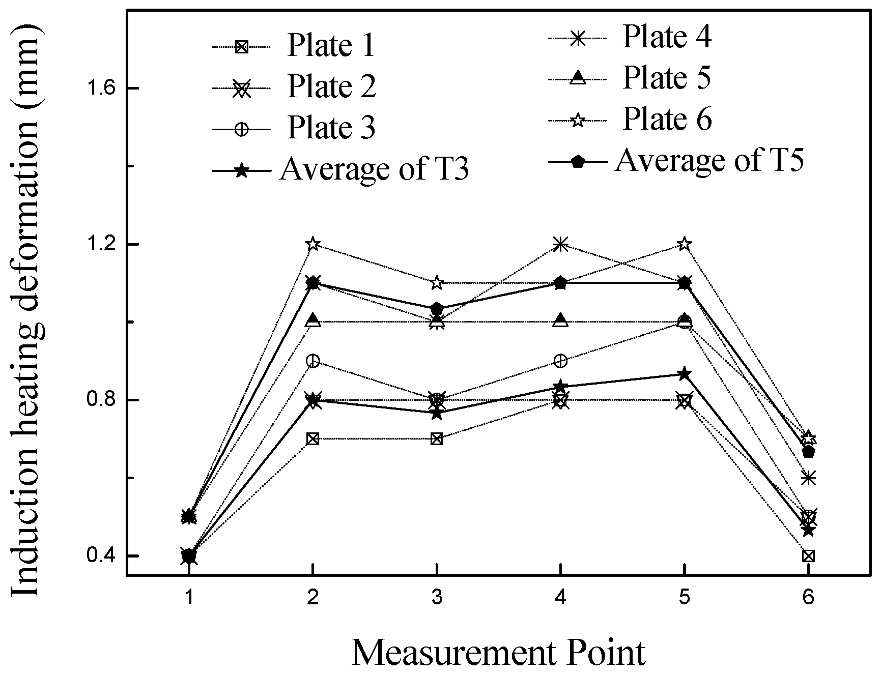
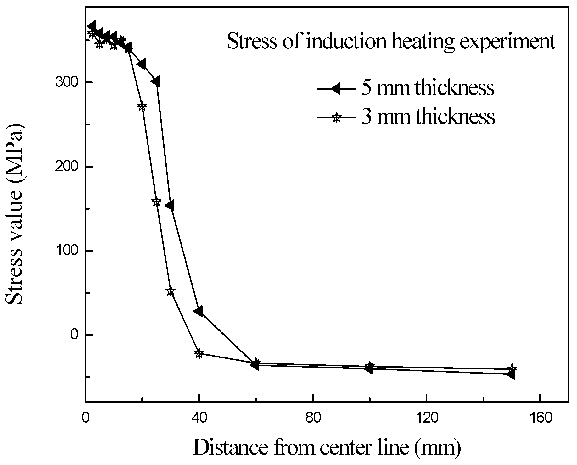
2.4.2. Induction Heating Experimental Results

After the sample was cooled (20 °C), at the same measuring position in the previous welding deformation, the deformation data and residual stress distribution of the structure were measured, then the deformation rectification amount under different induction parameters could be obtained. Induction heating parameters and deformation rectification amount are shown in Table 4. The deformation data of the measuring point after the induction heating experiment are shown in Figure 7. In the stress measurement experiment, the steel plates of No. 3 and No. 6 were selected as the measurement samples again, and the longitudinal residual stress (y-direction) after induction heating is shown in Figure 8.
The deformation results show that the welding deformation was reduced after induction heating, which indicates that induction heating was beneficial to the correction of welding deformation of thin plate structures. Furthermore, the influence of different induction heating parameters on the amount of deformation correction was obvious, hence, when the welding deformation is large, it is necessary to formulate a suitable induction heating process scheme, or even conduct multiple induction heating operations on the same deformed structure.
According to the comparison between the residual stress after welding and the residual stress after induction heating in Figure 8, the width of the longitudinal tensile residual stress concentration zone became larger after induction heating. As the distance between the measuring point and the weld increases, the stress value decreased rapidly, and then the tensile stress became compressive stress. This was because the width of the induction heating heat source was greater than the width of the welding heat source, resulting in an increase in the width of the heated area. At the same time, due to the thin thickness of the plate, the base plate was easy to heat penetrated, so large heat was generated on both sides of the plate during induction heating, thus more obvious residual stress would be generated.

3. Finite Element Simulation Modeling and Precision Analysis

3.1. Simulation Modeling Methodology

3.1.1. Background of Modeling Idea

Based on the welding simulation technology of thermo-elastic-plastic finite element method, the more accurate welding heating and deformation process can be calculated; especially the application of element birth and death technique in the weld area, the process of molten pool from scratch can be accurately simulated [12,28]. In the welding model, the thermal load is loaded on the nodes of the weld area, and the dynamic heating process of the specimen is simulated through the constant change of the loading position, so as to calculate the temperature field of the structure. After the temperature field calculation is completed, the temperature results of each node at different load steps are loaded into the structural field calculation as loads, and finally the post welding stress and deformation morphology can be obtained [10,19].
Similarly, when the induction heating process is simulated, firstly, the electromagnetic load should be applied to the node of the specimen unit, and the thermal load shall be calculated according to the electromagnetic load. After the electromagnetic heat generation process is calculated, the structural field shall be calculated according to the calculated data of the temperature field [21].

3.1.2. Holistic Modelling Logic

According to the experimental logic of welding-induction heating, when simulating the process of rectifying welding deformation by induction heating, it is necessary to apply electromagnetic load on the structural field of welding simulation calculation, and then calculate the electromagnetic heat generation and structural deformation [29]. However, in practical operation, it is difficult to complete this sequence of construction steps [30]. In order to solve this problem, the use of multiple physical fields in the finite element software was analyzed. It can be found that, in the simulation modeling, the logical order of each physical field can be reasonably changed, then the welding—induction heating experimental process can be effectively simulated.
During welding, the temperature field is converted into the structure field; during induction heating, the electromagnetic field is converted into temperature field, and then converted into structure field after calculation. According to the similar transformation idea, the temperature field in the welding process is combined with the electromagnetic field and temperature field in the induction heating process. First, the thermal load is completely calculated, and then the thermal load is included in the calculation of the structural field. Then, the simulation sequence of welding deformation rectification process is changed to calculate welding temperature field, induced electromagnetic field, induced temperature field, welding structure field and induced structure field in turn. Based on this mentality, overall simulation of welding-induction heating was performed by Ansys FE software.

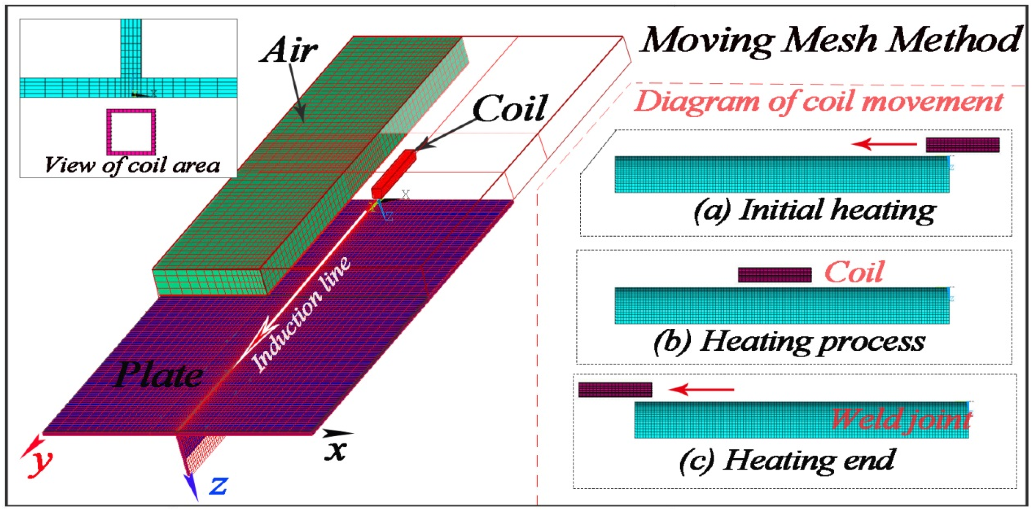
3.2. Integrate Model Based on the Moving Mesh Method

3.2.1. Modeling Methodology of the Moving Mesh Method

When the welding deformation is corrected by induction heating, the coil coordinate is dynamic. Different from the moving mode of welding heat source changing with the heat input load position, the heating position of the fillet welded joint in induction heating is determined by the coil position, so the coordinate of the coil relative to the specimen is required to change with time during calculating.
In the simulation of mobile induction bending and induction hardening, the moving mesh method is used more, and it simulates the relative movement between the electromagnetic equipment and the workpiece through the constraint equation.
During modeling, the static part and the moving part in the model are separately meshed, after the relative positions of the moving and stationary components at the initial time are determined, the electromagnetic vector of the element node on the interface between them is constrained to be equal, so the normal electromagnetic vector potential at the interface is continuous. When moving, the constraint equation is deleted, and after moving, the constraint equation is re-imposed, so that the moving heating process can be realized through repeated operations. This method can avoid the mesh re-division for moving, but, when the mesh difference on the interface is large, it may cause distortion of calculation results.
According to the experimental process of welding deformation rectification by induction heating, the moving mesh method was selected to simulate the moving process of the induction coil. Figure 9 shows the coil movement in the welding induction heating model.
In this model, the classical double ellipsoidal heat source [31] is used to simulate the welding heat source. In the source parameters, the front half axis length was 4 mm, the rear half axis length was 7 mm, the half width was 4 mm, and the molding depth was 3 mm. The coil model was modeled according to the actual coil, with the coil length of 100 mm, width and height of 10 mm, and the distance from the coil to base plate was set to 3 mm.
Figure 9 shows the shape and size scale information of the mesh model. The steel plate, coil and air models were all three-dimensional solid models, and the surface of the steel plate was equipped with two-dimensional surface effect elements. Both the steel plate and coil models were set in rectangular shape. The air models were composed of rectangular elements in the far coil area and tetrahedral elements in the near coil area. In this paper, the 3D elements SOLID70 and SOLID97 were meshed for the welding process and induction heating process, respectively, and the 3D element SOLID45 was used for structural analysis. In order to ensure the calculation accuracy of the established model, the elements close to the heating area in the specimen were divided closely, and the elements far away from the heating area were divided sparsely.
The cross-section size of the steel plate grid in the weld area was set to 1 × 1 × 1 m3, in the top of the rib and the edge of the base plate far from the weld area, the size of the steel plate grid gradually increases, and the length of all steel plate grids was set to 5 mm. The coil size was set to 1 × 1 × 1 mm3, the length of weld direction in the specimen was divided into 5 mm, the grid size near the weld area was smaller, while the grid size far away from the weld area was larger, and the smallest size of elements in the specimen was 1 × 5 × 1 mm3. When the plate thickness was 5 mm, 157,109 elements and 97,580 nodes were generated in the model. When solving, nonlinear default setting was activated, and the full Newton-Raphson method was applied to solve transient analysis.
In the welding simulation, in order to simplify the modeling procedure and speed up the calculation efficiency, a rectangular weld model was set in the contact area between the rib and the base plate, and the weld seam element was divided into small cubes. The SOLID70 was selected for welding heat transfer calculation and the SOLID45 was used for stress analysis. Considering that the induction heating process requires air and coil to participate in the calculation of electromagnetic heat generation, then, the air elements, coil elements and specimen elements should be established together at the initial stage of modeling. To ensure the accuracy of constraint equation calculation, the air area between coil and specimen surface was divided into static air area (closed to the specimen) and moving air area (closed to the coil). The element nodes at the interface between them were the nodes of the constraint equation, so the elements on both sides of the interface were classified as the same. At the same time, the element size needed to be coordinated with the moving speed of the induction heating, consequently, the moving distance of each step could be divided by the size of the moving direction of the element.
During welding thermal analysis, all air elements and coil elements were killed, and only the specimen elements was heated. The surface effect elements were applied to calculate the convection heat transfer between the specimen and the air. The welding thermal efficiency was set to 50% and initial temperature was set at 20 °C. The temperature-dependent material properties [32] c could be taken from Figure 10. After calculating the welding temperature field, the air and coil elements were activated to calculate the electromagnetic field. Once the electromagnetic heat generation process was calculated, the constraint equation was deleted, the moving area elements were moved to the next heating point according to the induction heating speed, and then the nodes at the interface were re-constrained for calculation.

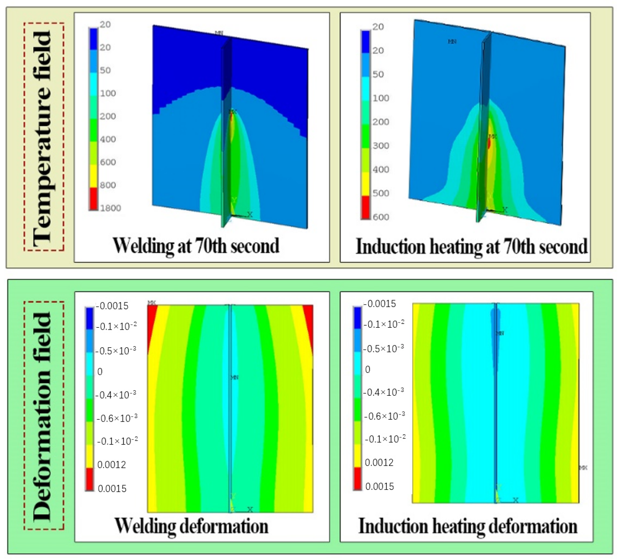
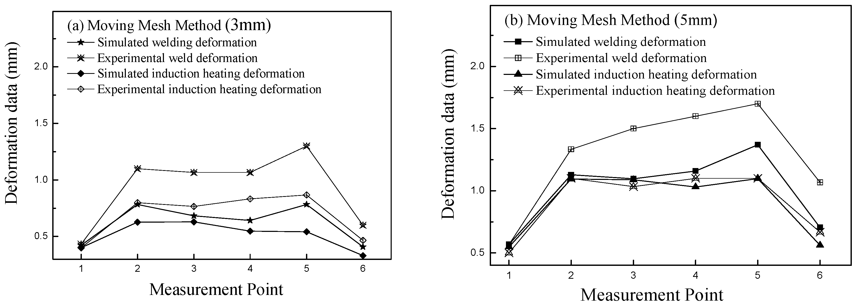
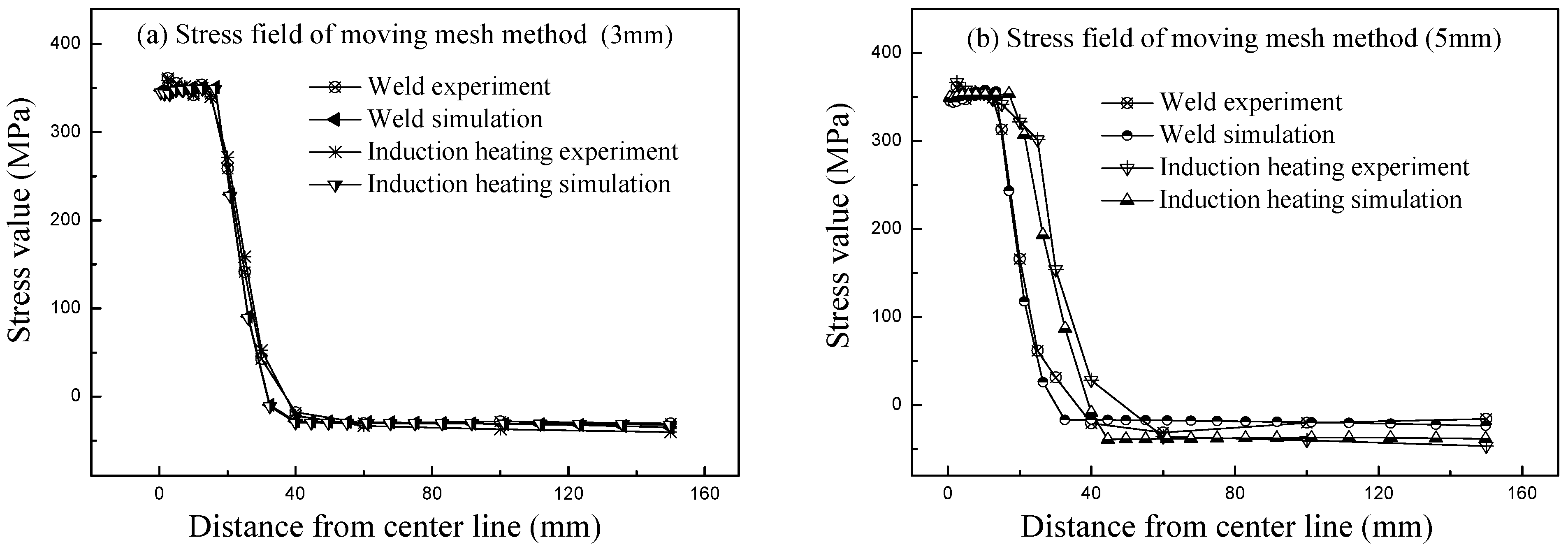
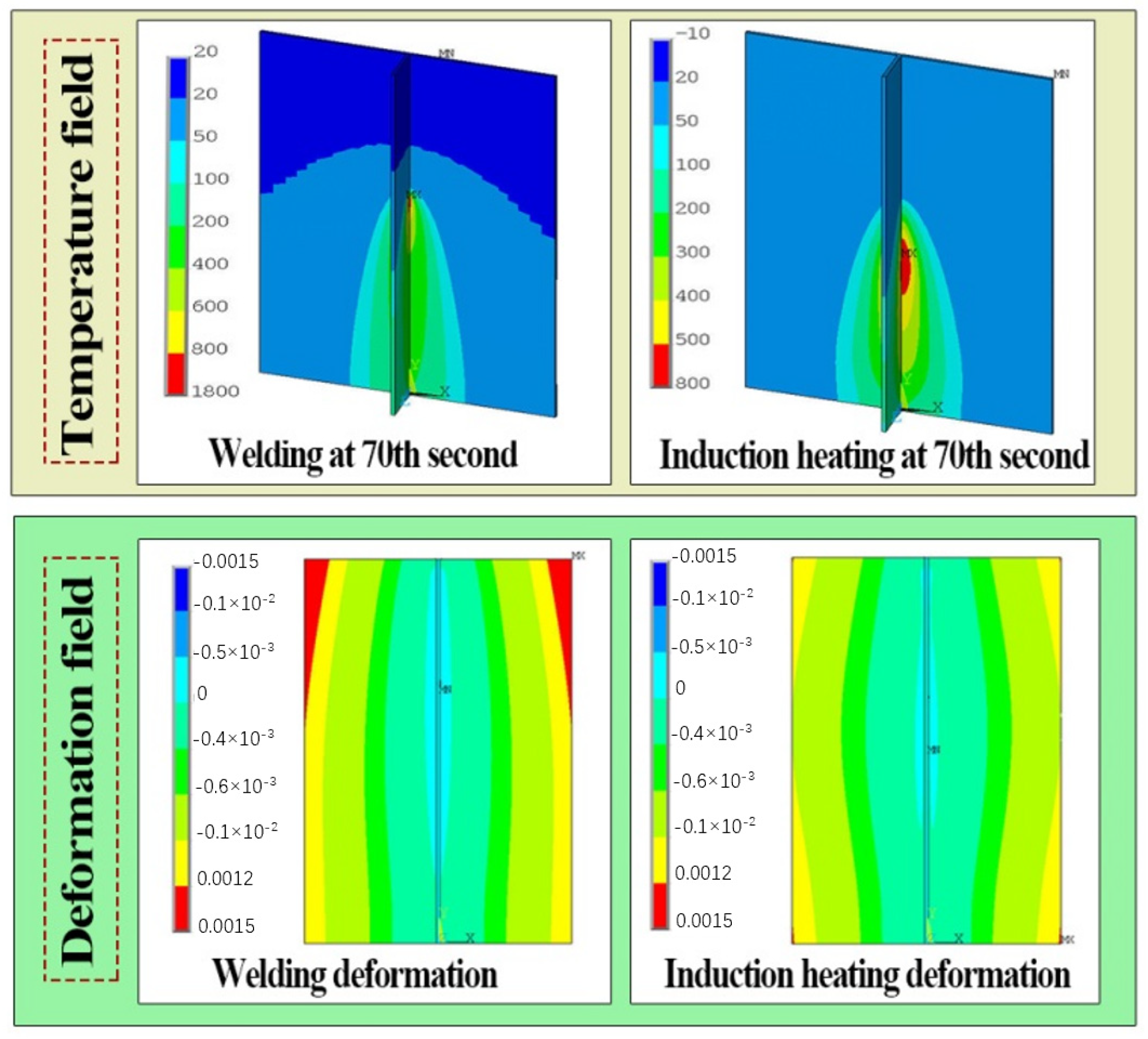
3.2.2. Simulation Results of the Moving Mesh Method

In this paper, the 3D elements SOLID70 and SOLID97 were meshed for the welding process and induction heating process, respectively, and the 3D element SOLID45 was used for structural analysis. In order to ensure the calculation accuracy of the established model, the elements close to the heating area in the specimen were divided closely, and the elements far away from the heating area were divided sparsely. The coil size was set to 1 × 1 × 1 mm3; the length of weld direction in the specimen was divided into 5 mm, the grid size near the weld area was smaller, while the grid size far away from the weld area was larger, and the smallest size of elements in the specimen was 1 × 5 × 1 mm3. When the plate thickness was 5 mm, 157,109 elements and 97,580 nodes were generated in the model. When solving, nonlinear default setting was activated, and the full Newton-Raphson method was applied to solve transient analysis.
After the process of electromagnetic heat generation was calculated, all temperature results were loaded into the structural field as loads, and the elements of the specimen could calculate the welding deformation and induction heating deformation in turn. In the calculation of structural field, fixed constraints were applied to the nodes near the two ends of the weld. When the plate thickness is 5 mm, the temperature and deformation distribution of the fillet welded joint obtained by the moving mesh method are shown in Figure 11.
To verify the accuracy of the simulation model, the simulation deformation results were compared with the experimental measurement data, as shown in Figure 12. The comparison results of longitudinal residual stress are shown in Figure 13.
The induction heating model established by moving mesh method could show a distribution law consistent with the experimental results. Compared the calculation results of welding deformation, the places with the greatest welding deformation were at the corners of the base plate in the direction of the end of the weld, and when the plate was thicker, the deformation was greater; when the welding deformation was larger, the effect of induction heating correction was more obvious. The maximum deformation rectification was located at the corner of the base plate, which was consistent with the experimental results. The deformation error obtained from experiment and simulation was large, the reason was that the constraints imposed by the model cannot be fully operated according to the actual experiment. In the study, with appropriate constraints, the whole model of welding deformation rectification by induction heating established by moving mesh method can reflect the variation law of strain field.
By comparing the distribution results of residual stress, it can be seen that the distribution of calculated residual stress highly conformed to the actual state. The high stress area was mainly distributed near the weld and the induction heating line. In addition, when the plate was thin, the distribution of welding residual stress and the induction heating residual stress were basically coincident; however, when the plate was thick, the area of high residual stress generated by induction heating was obviously larger than the welding residual stress. This was because when the thickness was thin, the welding heat could quickly penetrate both sides of the base plate, so the welding heat source produced a larger area of high residual stress distribution on the back of the base plate; and when the plate thickness was large, it was difficult for the welding heat source to completely heat through both sides of base plate, the width of the high residual stress area at the back was small. This model can accurately describe the evolution of residual stress during induction heating correction. Considering the experimental operation error and measurement process error, the model based on moving mesh method can accurately describe the whole process of welding deformation rectification by mobile induction heating.

3.3. Integrate Model Based on the Moving Mesh Method

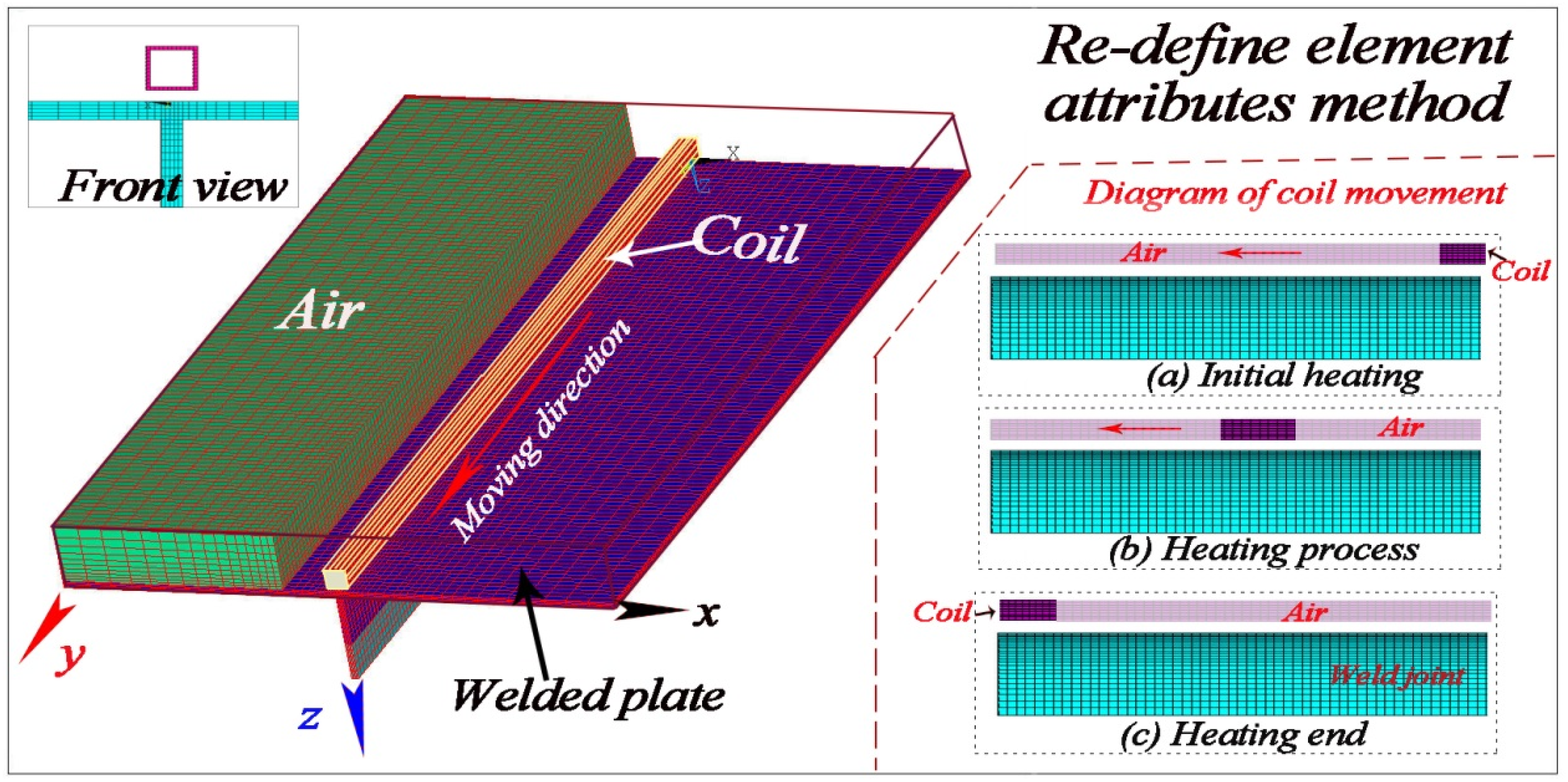
3.3.1. Modeling Methodology of the Re-Defined Element Attributes Method

When using the moving mesh method for modeling, it is found that the model needs to be divided into moving area and static area. The constraint equation of the model is affected by the quality of the interface element. Every time a load step is completed, the constraint equation needs to be deleted and re-applied. Similarly, the boundary conditions around need to be re-applied, this leads to a troublesome calculation process [17,22]. Moreover, the interface is affected by the path of induction heating, which causes the shape of induction heating line to be straight [11,13].
In the thermal structure coupling calculation, by changing the element properties and physical environment, the structural field can be calculated after the temperature field calculation is completed. Similar methods can be selected to simulate the movement process of the induction coil.
After the induction heating at the initial position is completed, the attributes of the current coil elements are re-defined as the attributes of air, and then the attributes of the coil are applied to the elements in the coil area at the next heating position, the electromagnetic heating can be calculated. Repeat this step continuously, the coil elements will move with the preset position of the heating wire, finally the process of mobile induction heating can be realized. The induction heating process based on is shown in Figure 14.
Compared with the moving mesh method, the re-defined element attributes method is simpler and more flexible. It is not necessary to consider the division of moving part and stationary part, and the steps of repeatedly deleting and imposing constraint equations and boundary conditions are omitted, as well as the requirement for regularity of induction heating path is very low. In modeling, re-defined element attributes method required to divide the elements according to the moving route of the coil in the experiment, and then change a small amount of element attributes at different load steps according to the heating time, so as to realize the moving induction heating process more efficiently.

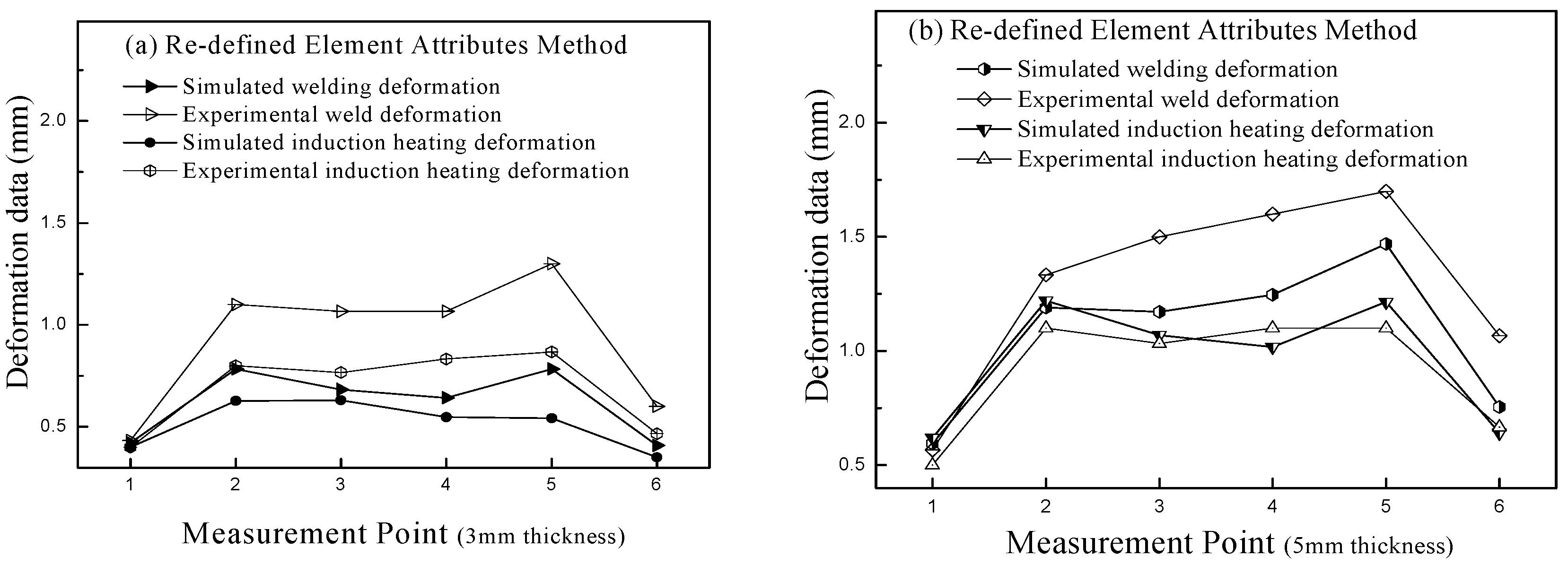
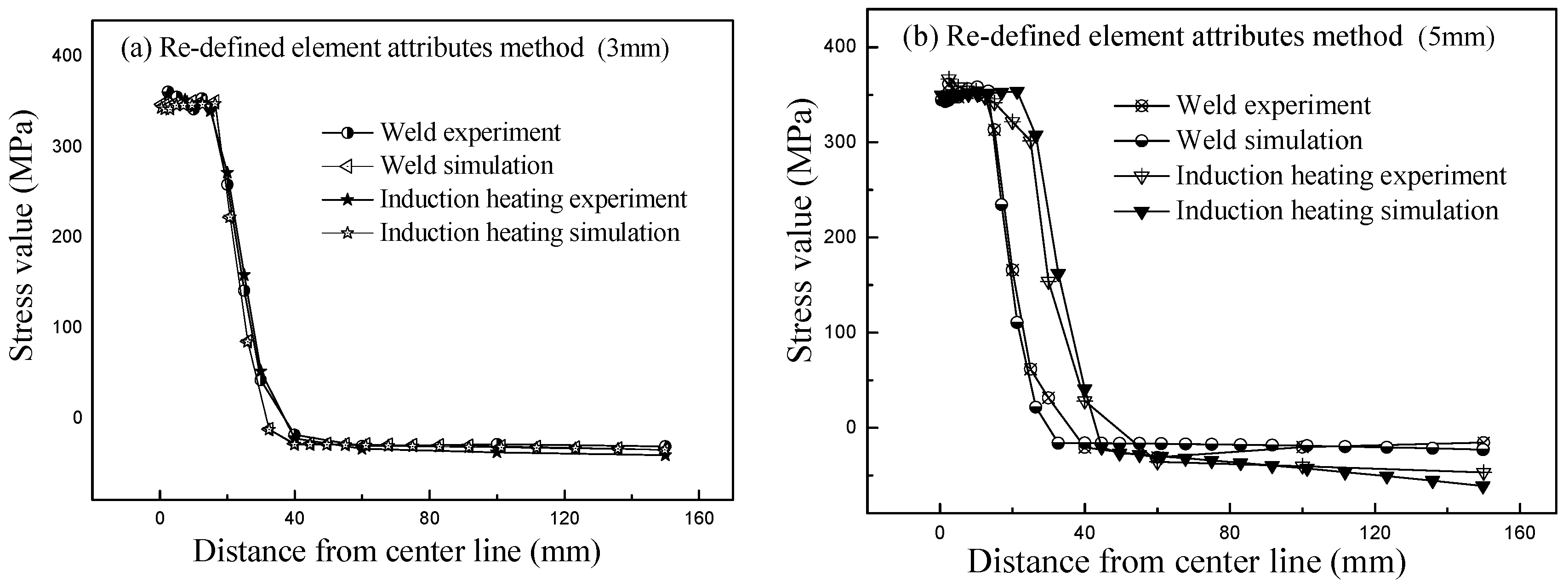
3.3.2. Simulation Results of the Re-Defined Element Attributes Method

When the re-defined element attributes method was applied to modeling, the boundary conditions of temperature field and structure field were the same as those applied in the moving mesh method, and the elements of coils and welded joints were divided into the same. The same solution method and simulation steps should be used for solution. The distribution of temperature and deformation during induction heating is shown in Figure 15.
It can be seen from the comparison data that the temperature field and deformation field calculated by the two methods, the temperature field and deformation field generated during welding were highly consistent; in the process of induction heating process, the model based on re-defined element attributes method had a higher induction temperature maximum. The reason for analysis was that when using the moving mesh method to calculate the temperature field, the constraint equation depended on the grid quality and the location of the interface nodes. When the coil moved, some nodes couldn’t to be conducted heat transfer calculation; therefore, it would cause partial distortion of the calculation results.
After the model calculation was completed, the deformation and longitudinal stress distribution (y-direction) based on re-defined element attributes method are shown in Figure 16 and Figure 17, respectively.
Figure 16 shows that the deformation law obtained based on re-defined element attributes method was consistent with the experimental results. There was a large error between the deformation calculated by the model and the experimental deformation. The reason for this phenomenon was that the constraint conditions of the model couldn’t fully conform to the experimental conditions. When the deformation results of the moving mesh method and re-defined element attributes method were compared, it was known that the re-defined element attributes method had smaller error and higher deformation field simulation accuracy.
Figure 17 shows the distribution of longitudinal residual stress after welding and induction heating was highly matching to the actual measured value. The high stress area was mainly distributed near the weld and the induction heating line; when the thickness of steel plate was larger, the area of high stress zone generated by induction heating was larger. As the distance between the measuring point and the weld increased, the residual stress decreased rapidly, and when the distance was greater than 40 mm, the tensile stress was converted into a smaller compressive stress. When the residual stress fields calculated by the two models were compared, it can be seen that the high induction heating residual stress area calculated by re-defined element attributes method was larger than that calculated by moving mesh method. This was because the high temperature area calculated by re-defined element attributes method was more significant, so the heat affected area generated was wider. When the residual stress calculated by the two models was compared with the experimental results, the error calculated by re-defined element attributes method was smaller, which illustrated this model had higher simulation.

4. Result and Discussion

The welding experiment results show that the maximum deformation caused by welding was located at the edge of the base plate, and the overall deformation law was relatively uniform. In addition, the induction heating experiment results indicate that induction heating can be beneficial to the correction of welding deformation of thin plate structures. Furthermore, the influence of different induction heating parameters on the amount of deformation correction was obvious, hence, when the induction heating process is applied to welding deformation correction, it is necessary to formulate a suitable process scheme.
The stress measurement results show that the longitudinal residual stress had a similar distribution law after welding experiments on the plates with different thicknesses, and the larger stress concentration was distributed within 30 mm of the weld line. However, after induction heating, the width of the longitudinal tensile residual stress concentration zone became larger. Besides, as the distance between the measuring point and the weld increases, the stress value decreased rapidly, and then the tensile stress became compressive stress.
Based on the above modeling analysis, it can be seen that the integrated welding-induction heating models established by the moving mesh method and the re-defined element attributes method had high accuracy and reliability. In the models, the distribution law of longitudinal residual stress was basically consistent with experimental results, and the evolution law of deformation rectification amount was similar to the experimental condition. In addition, the established model based on re-defined element attributes method showed higher induction heating temperature and greater deformation correction, which was more consistent with the experimental results. Consequently, the integrated model established by re-defined element attributes method can be effectively applied in the study of welding deformation rectification by induction heating.

5. Conclusions

Based on the experimental process of welding deformation rectification by induction heating, the modeling methods of the integrated model of welding—induction heating process was studied, and the characteristics of the models were evaluated and discussed. The research conclusions are as follows:
  • The integrated models based on moving mesh method and re-defined element attributes method can accurately simulate the physical fields of welding—induction heating construction process.
  • The progressive model based on re-defined element attributes method has higher accuracy, and is more convenient and flexible to study the induction heating correction process.
  • An appropriate induction heating scheme can effectively correct the welding deformation of the thin plate.

Author Contributions

Conceptualization, Y.F. and J.W.; methodology, Y.F.; software, Y.F.; validation, Y.L.; formal analysis, R.L.; writing—original draft preparation, Y.F.; writing—review and editing, J.W. All authors have read and agreed to the published version of the manuscript.

Funding

This research was funded by National Natural Science Foundation of China, grant number 51979033 and Dalian Science and Technology Innovation Fund Project, grant number 2019J12GX021.

Institutional Review Board Statement

Not applicable.

Informed Consent Statement

Not applicable.

Data Availability Statement

Not applicable.

Conflicts of Interest

The authors declare no conflict of interest.

References

  1. Li, L.; Luo, C.; Shen, J.; Zhang, Y. Numerical prediction of welding deformation in ship block subassemblies via the inhomogeneous inherent strain method. J. Manuf. Process. 2022, 80, 860–873. [Google Scholar] [CrossRef]
  2. Woo, D.; Kitamura, M. Optimal simultaneous welding to minimise welding deformation of a general ship grillage structure. Ships Offshore Struc. 2022, 17, 268–278. [Google Scholar] [CrossRef]
  3. Kalyankar, V.D.; Shah, P. A review on methodologies to reduce welding distortion. Mater. Today Proc. 2018, 5, 24741–24749. [Google Scholar] [CrossRef]
  4. Mishra, A.; Bag, S.; Pal, S. Induction Heating in Sustainable Manufacturing and Material Processing Technologies—A State of the Art Literature Review. Encycl. Renew. Sustain. Mater. 2020, 1, 343–357. [Google Scholar]
  5. Li, Y.; Li, Y.; Ma, X.; Zhang, X.; Fu, D.; Yan, Q. Study on Welding Deformation and Optimization of Fixture Scheme for Thin-Walled Flame Cylinder. Materials 2022, 15, 6418. [Google Scholar] [CrossRef] [PubMed]
  6. Li, L.; Mi, G.; Wang, C. A comparison between induction pre-heating and induction post-heating of laser-induction hybrid welding on S690QL steel. J. Manuf. Process. 2019, 43, 276–291. [Google Scholar] [CrossRef]
  7. Barclay, C.J.; Campbell, S.W.; Galloway, A.M.; McPherson, N.A. Artificial neural network prediction of weld distortion rectification using a travelling induction coil. Int. J. Adv. Manuf. Technol. 2013, 68, 127–140. [Google Scholar] [CrossRef] [Green Version]
  8. Wang, C.; Kim, Y.R.; Kim, J.W. Numerical analysis of thermal deformation in laser beam heating of a steel plate. J. Mech. Sci. Technol. 2017, 31, 2535–2541. [Google Scholar] [CrossRef]
  9. Zhang, S.; Liu, C.; Wang, X. Optimisation research on inductor shape parameters for thermal forming behaviour of ship hull plate by moving induction heating. Ships Offshore Struc. 2019, 14, 853–866. [Google Scholar] [CrossRef]
  10. Pan, M.; Li, Y.; Sun, S.; Liao, W.; Xing, Y.; Tang, W. A Study on Welding Characteristics, Mechanical Properties, and Penetration Depth of T-Joint Thin-Walled Parts for Different TIG Welding Currents: FE Simulation and Experimental Analysis. Metals 2022, 12, 1157. [Google Scholar] [CrossRef]
  11. Nassiraei, H.; Lotfollahi-Yaghin, M.A.; Neshaei, S.A.; Zhu, L. Structural behavior of tubular X-joints strengthened with collar plate under axially compressive load at elevated temperatures. Mar. Struct. 2018, 61, 46–61. [Google Scholar] [CrossRef]
  12. Chen, Z.; Duan, Y.; Wang, P.; Qian, H. Residual Stress Redistribution Analysis in the Repair Welding of AA6082-T6 Aluminum Alloy Joints: Experiment and Simulation. Materials 2022, 15, 6399. [Google Scholar] [CrossRef] [PubMed]
  13. Dong, H.B.; Zhao, Y.; Yuan, H. Effect of Coil Width on Deformed Shape and Processing Efficiency during Ship Hull Forming by Induction Heating. Appl. Sci. 2018, 8, 1585. [Google Scholar] [CrossRef] [Green Version]
  14. Egger, C.; Lüchinger, M.; Schreiner, M.; Tillmann, W. Numerical Simulation of Tube Manufacturing Consisting of Roll Forming and High-Frequency Induction Welding. Materials 2022, 15, 1270. [Google Scholar] [CrossRef]
  15. Lionetto, F.; Pappadà, S.; Buccoliero, G.; Maffezzoli, A. Finite element modeling of continuous induction welding of thermoplastic matrix composites. Mater. Design 2017, 120, 212–221. [Google Scholar] [CrossRef]
  16. Bai, X.W.; Zhang, H.O.; Wang, G.L. Modeling of the moving induction heating used as secondary heat source in weld-based additive manufacturing. Int. J. Adv. Manuf. Technol. 2015, 77, 717–727. [Google Scholar] [CrossRef]
  17. Das, P.; Asperheim, J.I.; Grande, B. Three-dimensional numerical study of heat-affected zone in induction welding of tubes. COMPEL 2020, 39, 213–219. [Google Scholar] [CrossRef]
  18. Coors, T.; Pape, F.; Kruse, J.; Blohm, T.; Beermann, R.; Quentin, L.; Herbst, S.; Langner, J.; Stonis, M.; Kästner, M.; et al. Simulation assisted process chain design for the manufacturing of bulk hybrid shafts with tailored properties. Int. J. Adv. Manuf. Technol. 2020, 108, 2409–2417. [Google Scholar] [CrossRef]
  19. Li, Z.; Feng, G.; Deng, D.; Luo, Y. Investigating Welding Distortion of Thin-Plate Stiffened Panel Steel Structures by Means of Thermal Elastic Plastic Finite Element Method. J. Mater. Eng. Perform. 2021, 30, 3677–3690. [Google Scholar] [CrossRef]
  20. Kang, C.; Shi, C.; Liu, Z.; Liu, Z.; Jiang, X.; Chen, S.; Ma, C. Research on the optimization of welding parameters in high-frequency induction welding pipeline. J. Manuf. Process. 2020, 59, 772–790. [Google Scholar] [CrossRef]
  21. Sun, J.; Li, S.; Qiu, C.; Peng, Y. Numerical and experimental investigation of induction heating process of heavy cylinder. Appl. Therm. Eng. 2018, 134, 341–352. [Google Scholar] [CrossRef]
  22. Wen, H.Y.; Han, Y. Study on mobile induction heating process of internal gear rings for wind power generation. Appl. Therm. Eng. 2017, 112, 507–515. [Google Scholar] [CrossRef]
  23. Zhang, M.; Jia, X.; Tang, Z.; Zeng, Y.; Wang, X.; Liu, Y.; Ling, Y. A Fast and Accurate Method for Computing the Microwave Heating of Moving Objects. Appl. Sci. 2020, 10, 2985. [Google Scholar] [CrossRef]
  24. Han, Y.; Yu, E.L.; Zhao, T.X. Three-dimensional analysis of medium-frequency induction heating of steel pipes subject to motion factor. Int. J. Heat Mass Tran. 2016, 101, 452–460. [Google Scholar] [CrossRef]
  25. Zhang, S.; Liu, G.; Wang, X. Temperature and deformation analysis of ship hull plate by moving induction heating using double-circuit inductor. Mar. Struct. 2019, 65, 32–52. [Google Scholar] [CrossRef]
  26. Shokouhmand, H.; Ghaffari, S. Thermal analysis of moving induction heating of a hollow cylinder with subsequent spray cooling: Effect of velocity, initial position of coil, and geometry. Appl. Math. Model. 2012, 36, 4304–4323. [Google Scholar] [CrossRef]
  27. Lian, C.; Li, J.J.; Zhang, Y.; Huang, K.M. A General Inheritance Algorithm for Calculating of Arbitrary Moving Samples During Microwave Heating. IEEE Trans. Microw. Theory Tech. 2022, 70, 1964–1974. [Google Scholar] [CrossRef]
  28. Perić, M.; Garašić, I.; Gubeljak, N.; Tonković, Z.; Nižetić, S.; Osman, K. Numerical Simulation and Experimental Measurement of Residual Stresses in a Thick-Walled Buried-Arc Welded Pipe Structure. Metals 2022, 12, 1102. [Google Scholar] [CrossRef]
  29. Liu, M.; Ji, Z.; Fan, R.; Wang, X. Finite Element Analysis of Extrusion Process for Magnesium Alloy Internal Threads with Electromagnetic Induction-Assisted Heating and Thread Performance Research. Materials 2020, 13, 2170. [Google Scholar] [CrossRef]
  30. Cui, P.; Zhu, W.; Ji, H.; Chen, H.; Hang, C.; Li, M. Analysis and optimization of induction heating processes by focusing the inner magnetism of the coil. Appl. Energy 2022, 321, 119316. [Google Scholar] [CrossRef]
  31. Goldak, J.; Chakravarti, A.; Bibby, M. A new finite element model for welding heat sources. Metall. Mater. Trans. B 1984, 15B, 299–305. [Google Scholar] [CrossRef]
  32. Wang, Y. Investigation on Welding Residual Stress of TA2/Q345 Clad Plate Using Coverplate-Lap with Complex Structure. Master’s Thesis, Xi’an University of Technology, Xi’an, China, 2018. [Google Scholar]
Figure 1. Schematic diagram of welding process.
Metals 13 00425 g001
Figure 2. Diagram of deformation position measurement.
Metals 13 00425 g002
Figure 3. The experimental deformation results of welding process.
Metals 13 00425 g003
Figure 4. Schematic diagram of residual stress test.
Metals 13 00425 g004
Figure 5. The longitudinal residual stress (y-direction) after welding experiments: 3 mm thickness (Plate No. 3) and 5 mm thickness (Plate No. 6).
Metals 13 00425 g005
Figure 6. The experimental process for induction heating.
Metals 13 00425 g006
Figure 7. The deformation data of the measuring point after the induction heating experiment.
Metals 13 00425 g007
Figure 8. The longitudinal residual stress (y-direction) after induction heating: 3 mm thickness (Plate No. 3) and 5 mm thickness (Plate No. 6).
Metals 13 00425 g008
Figure 9. Simulation model based on moving mesh method.
Metals 13 00425 g009
Figure 10. Temperature-dependent material properties of Q345 steel.
Metals 13 00425 g010
Figure 11. Temperature and deformation distribution obtained by the moving mesh method (5 mm).
Metals 13 00425 g011
Figure 12. Comparison of the deformation between moving mesh method model and experiment. (a) 3 mm, (b) 5 mm.
Metals 13 00425 g012
Figure 13. Comparison of longitudinal residual stress between moving mesh method model and experiment. 3 mm thickness (Plate No. 3) and 5 mm thickness (Plate No. 6). (a) 3 mm, (b) 5 mm.
Metals 13 00425 g013
Figure 14. Principle of simulation model based on re-defined element attributes method.
Metals 13 00425 g014
Figure 15. Temperature and deformation distribution based on re-defined element attributes method (5 mm).
Metals 13 00425 g015
Figure 16. Comparison of longitudinal residual stress between re-defined element attributes method and experiment. (a) 3 mm, (b) 5 mm.
Metals 13 00425 g016
Figure 17. Comparison of longitudinal residual stress between re-defined element attributes method model and experiment. 3 mm thickness (Plate No. 3) and 5 mm thickness (Plate No. 6). (a) 3 mm, (b) 5 mm.
Metals 13 00425 g017
Table 1. Chemical composition of Q345 steel (ω%).
DesignationCSiMnPS
Q3450.150.551.450.0250.025
Table 2. Mechanical properties of Q345 steel.
DesignationYield Strength (MPa)Ultimate Strength (MPa)
Q345345600
Table 3. Process parameters and post-weld distortion data.
Plate No.Thickness
(mm)
Average Measured Weld Voltage (V)Average Measured Weld Current (A)Travel Speed (mm·s−1)Max Post-Weld Distortion (mm)
1318.412051.2
2318.511951.3
3318.511651.4
4518.511651.8
5518.412151.5
6518.712051.8
Table 4. Process parameters and rectification amount of induction heating experiment.
Plate No.Thickness (mm)Average Measured Frequency (kHz)Average Measured Process Current (A)Travel Speed (mm·s−1)Max Post-Weld Distortion (mm)Post-Induction Distortion (mm)Distortion Correction (mm)
1325.1151051.20.80.4
2325.5151051.30.80.5
3324.7151051.41.00.4
4527.3228051.81.10.7
5527.8228051.51.00.5
6527.0228051.81.20.6
Disclaimer/Publisher’s Note: The statements, opinions and data contained in all publications are solely those of the individual author(s) and contributor(s) and not of MDPI and/or the editor(s). MDPI and/or the editor(s) disclaim responsibility for any injury to people or property resulting from any ideas, methods, instructions or products referred to in the content.

