
Review: The Metal Additive-Manufacturing Technology of the Ultrasonic-Assisted Wire-and-Arc Additive-Manufacturing Process

Abstract
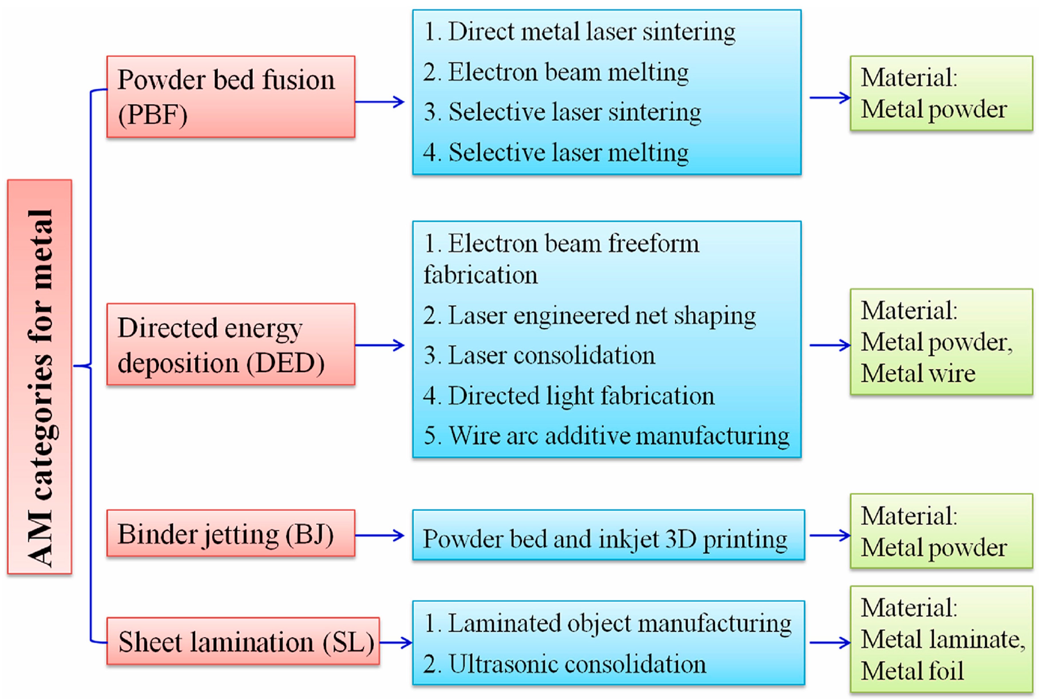
:1. Introduction
- Binder jetting;
- Directed energy deposition;
- Powder bed fusion;
- Sheet lamination;
- Material extrusion;
- Material jetting;
- Vat photo polymerization.
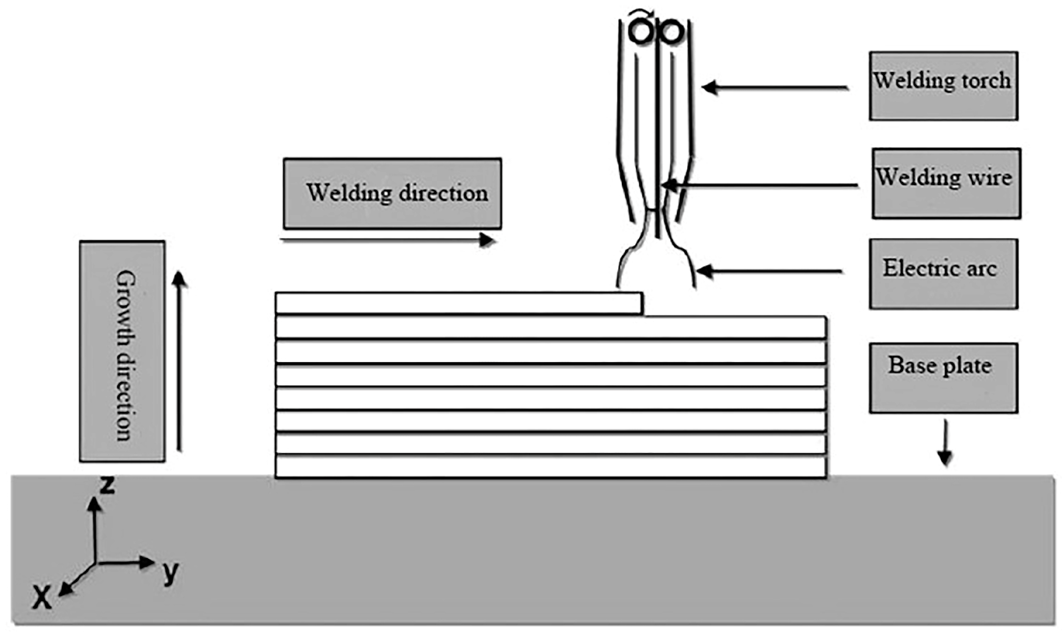
2. Introduction of Wire–Arc Additive Manufacturing
2.1. Characteristics of Wire–Arc Additive Manufacturing
- (1)
- The material utilization and manufacturing efficiency
- (2)
- The size of the product
- (3)
- The composition and high compactness of the product
2.2. Defects in the WAAM
- (1)
- Porosity
- (2)
- Residual stress and deformation
3. The Current Status of Ultrasound-Assisted Development
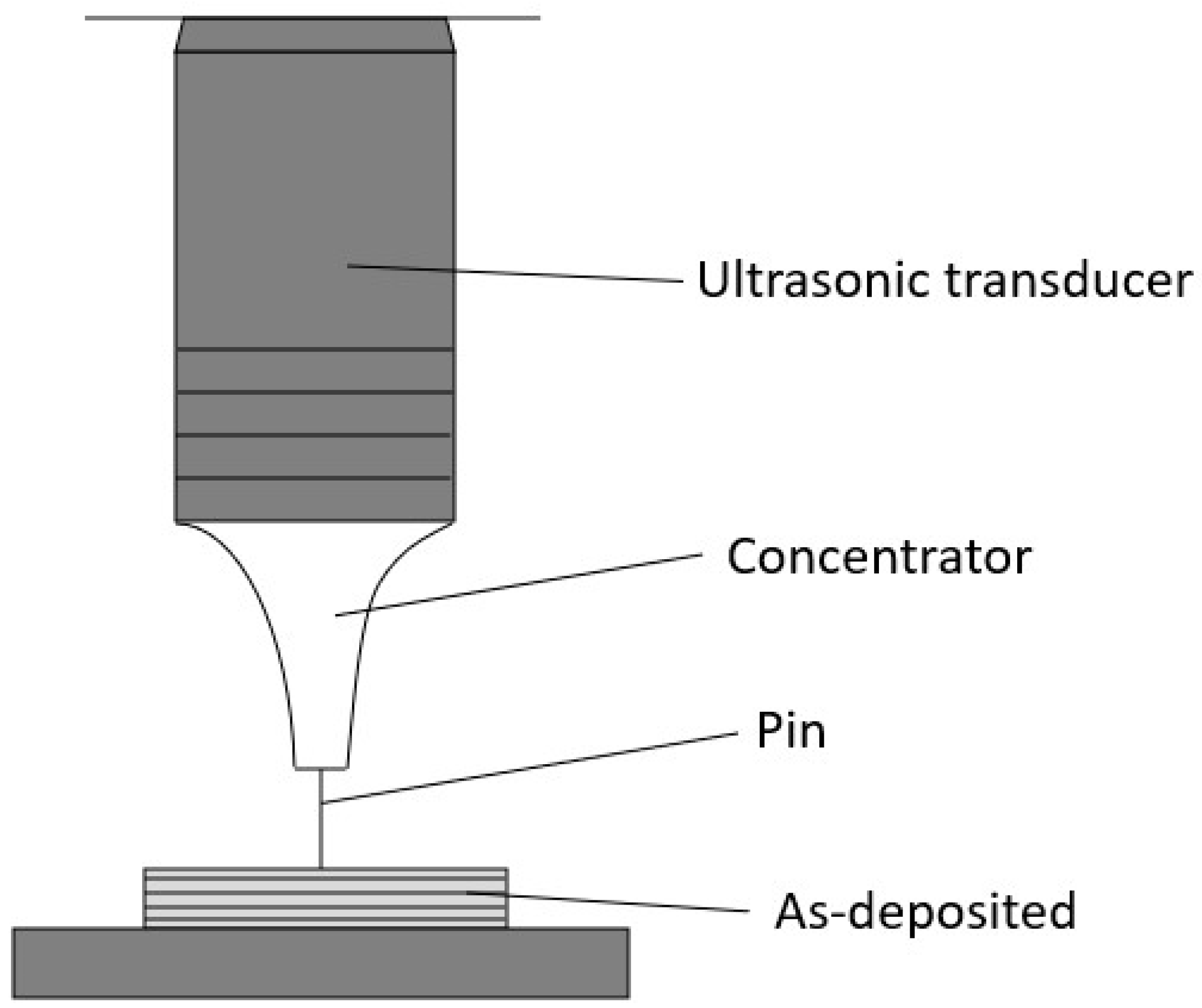
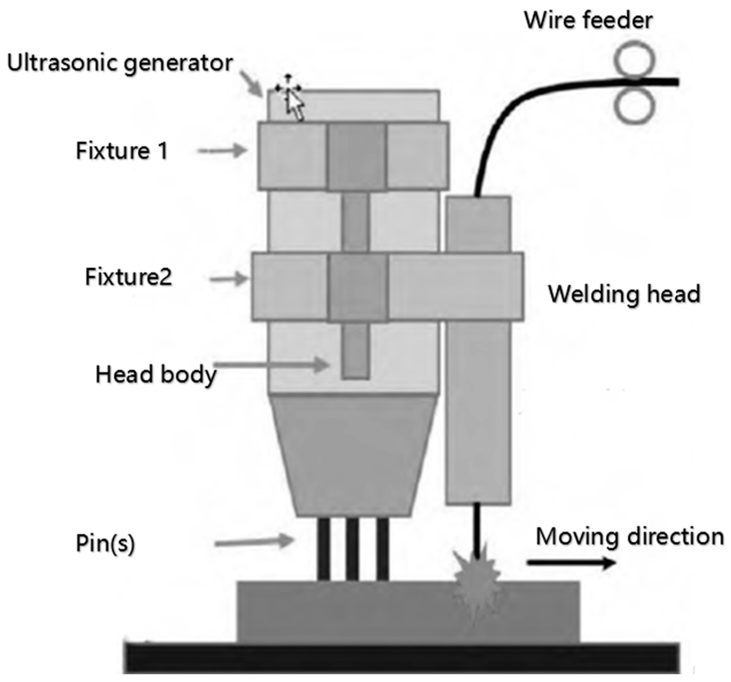
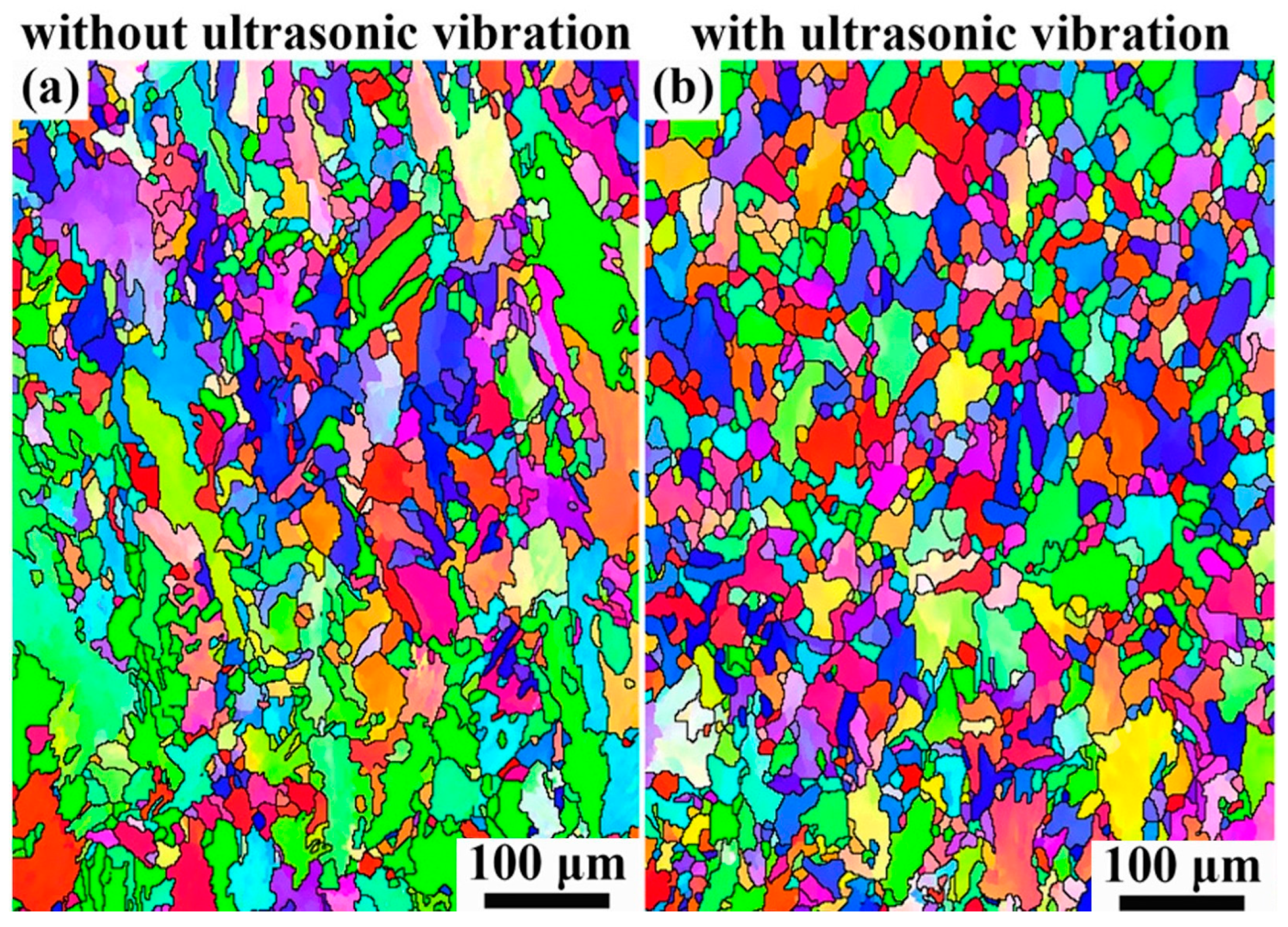
3.1. Ultrasonic Vibration-Assisted Technology
3.2. Ultrasonic Impact Treatment Technology
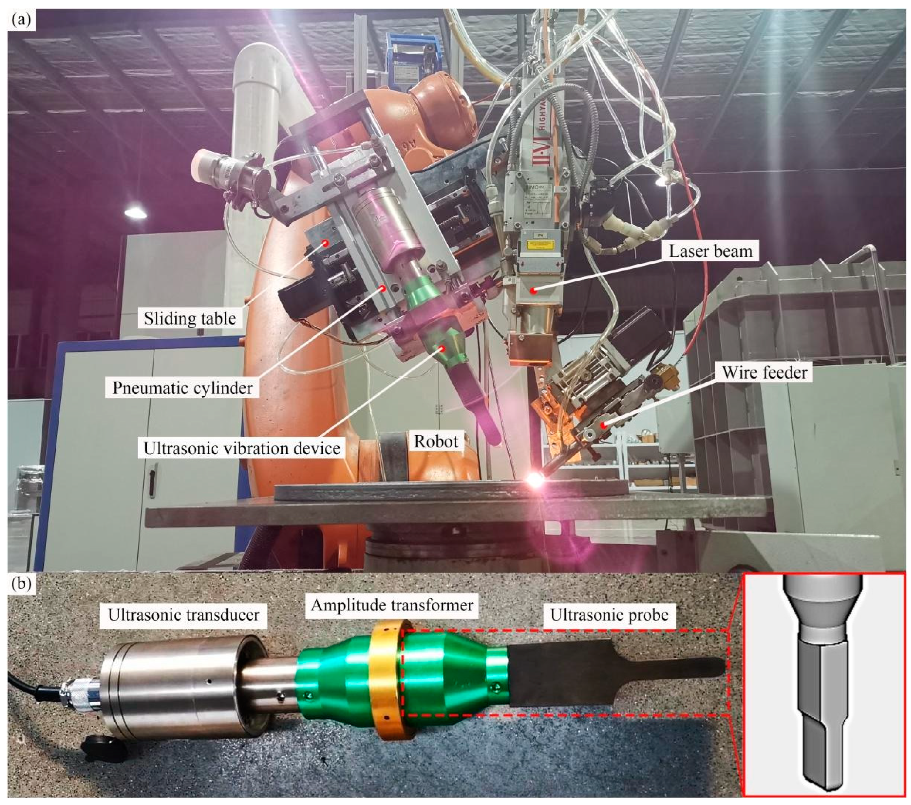
4. UIT-Assisted WAAM
4.1. Ultrasonic-Assisted Elimination of Residual Stress
4.2. Ultrasound-Assisted Preparation of Nano-Layer on Metal Surface
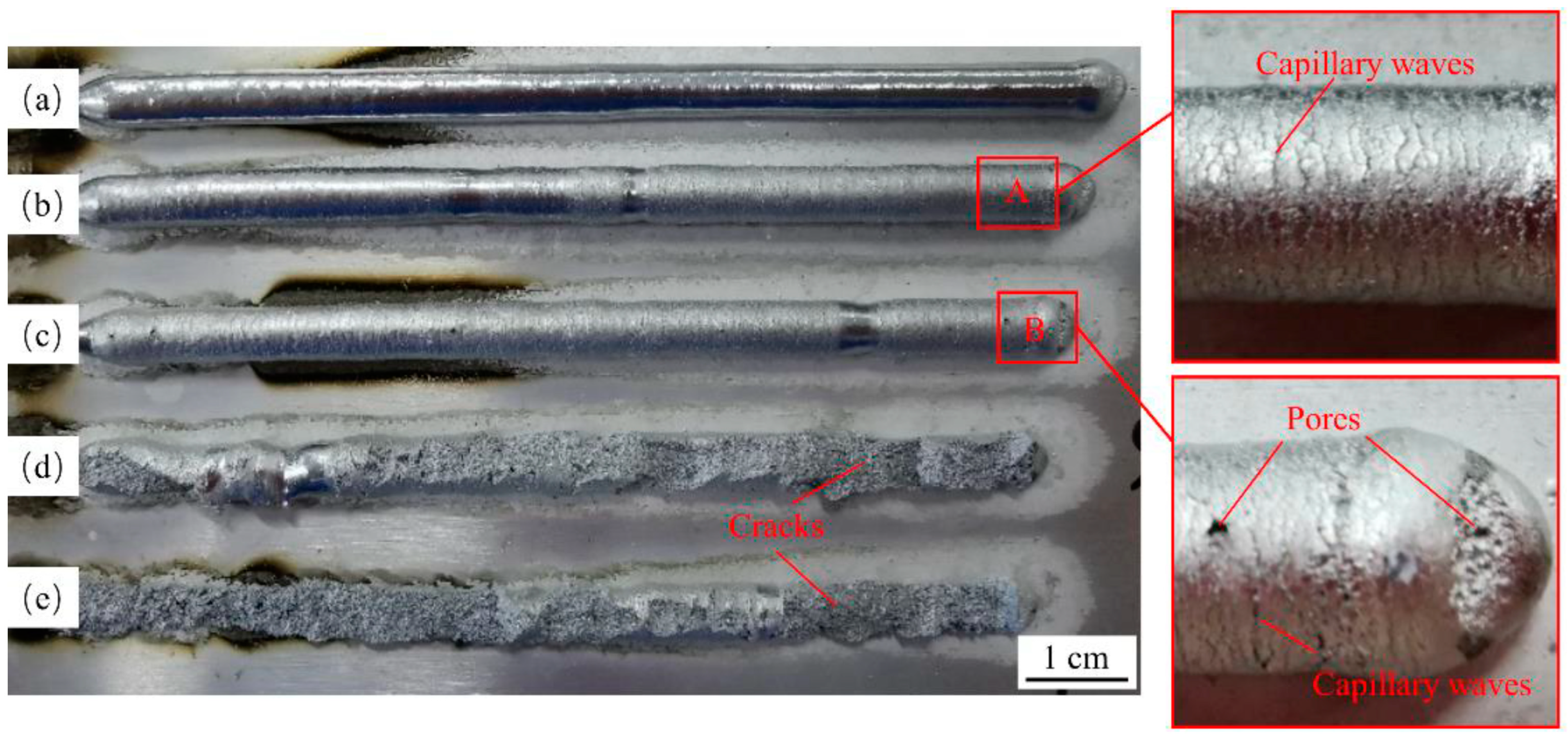
4.3. Ultrasound-Assisted Improvement of Morphology
4.4. Ultrasonic-Assisted Improvement of Fatigue Strength
4.5. Other Methods
5. Ultrasound-Assisted Process Parameters
5.1. Ultrasonic Amplitude
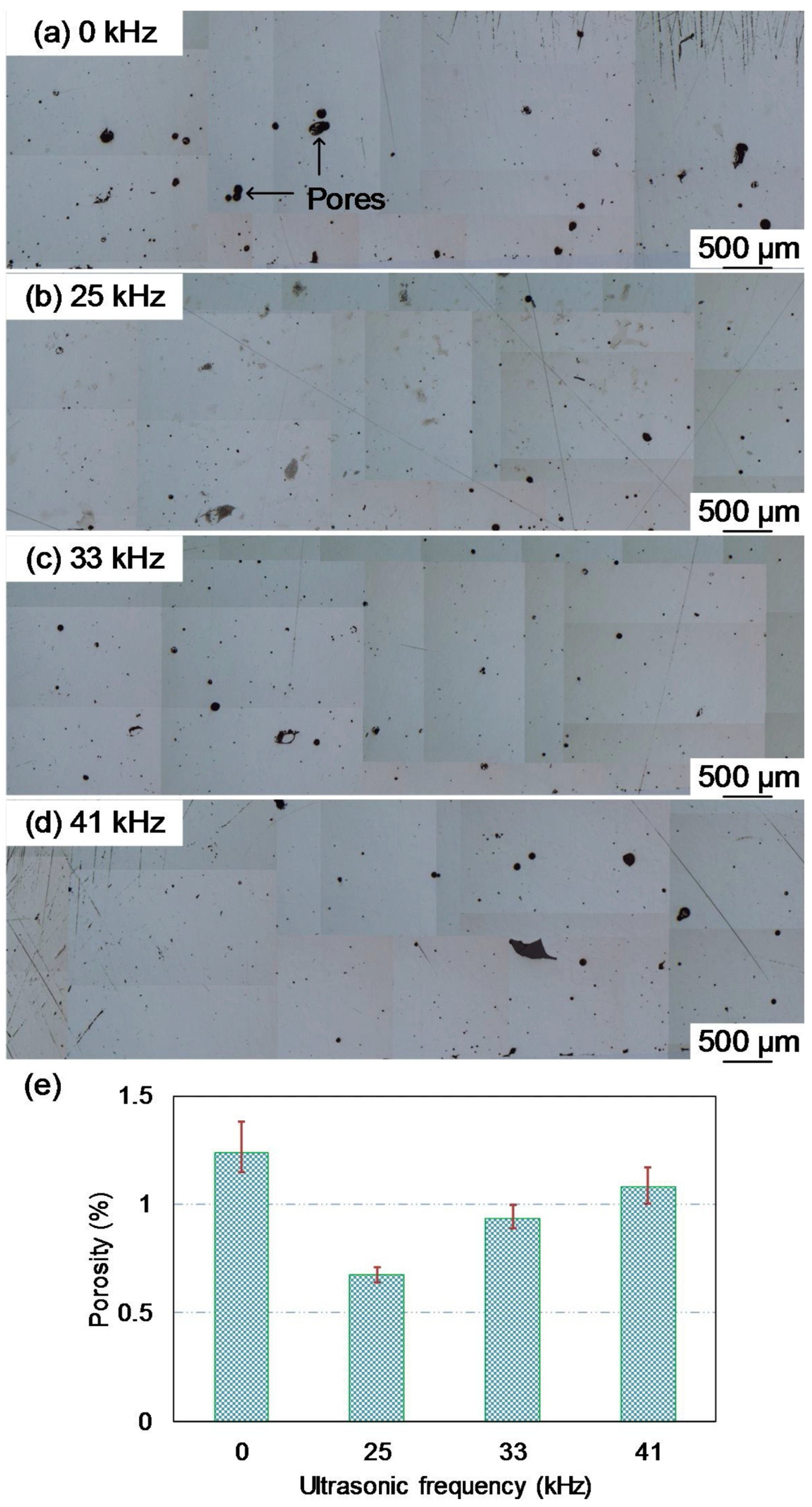
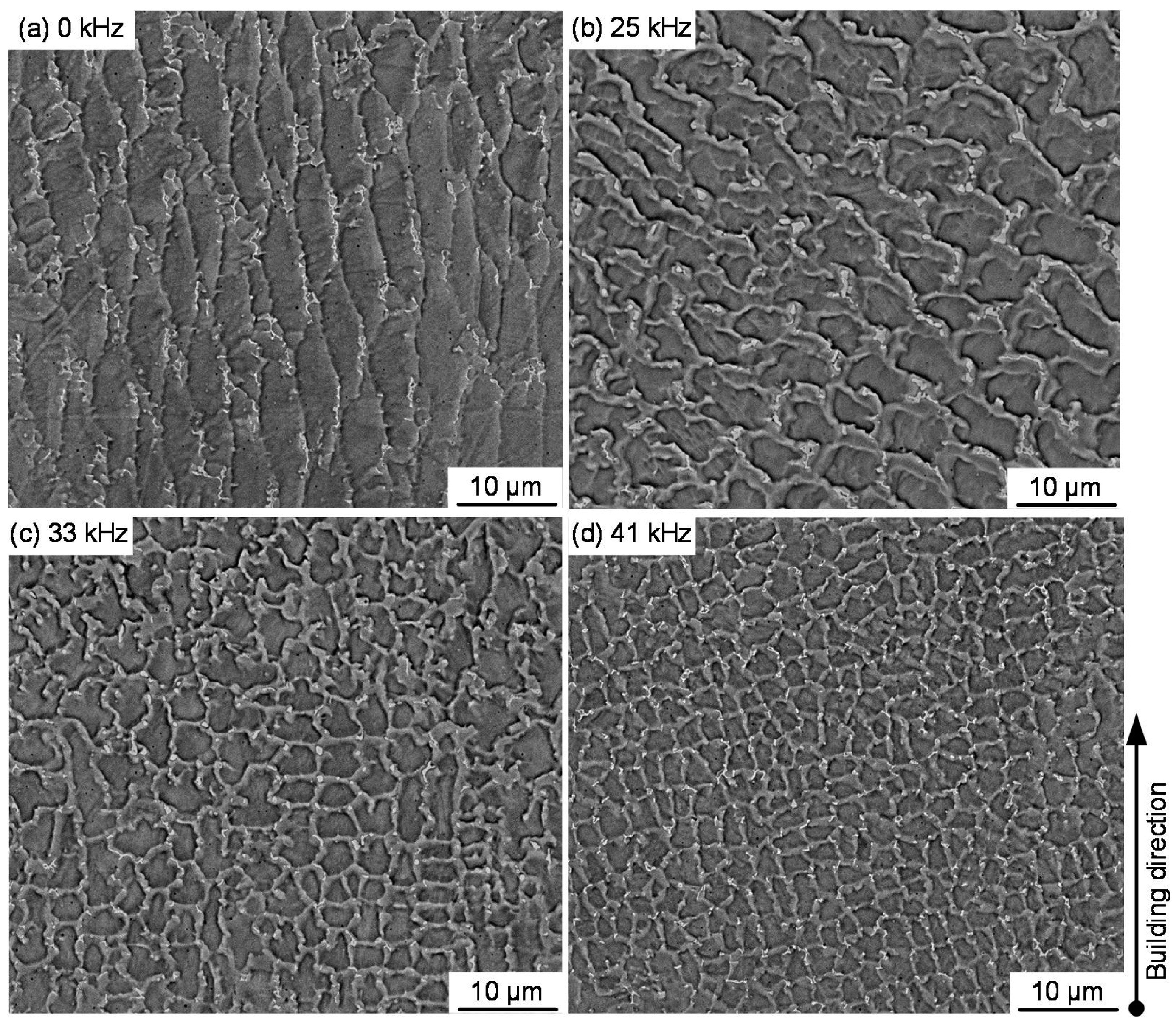
5.2. Ultrasonic Frequency
5.3. Ultrasonic Impact Scanning Speed
5.4. Ultrasonic Impact Times
5.5. Action Direction of Ultrasonic Vibration
6. Conclusions
- Ultrasonic assistance has been continuously combined with WAAM to consolidate large-size continuous materials and rapid precision manufacturing ability, which can effectively improve the microstructure and mechanical properties.
- Ultrasonic-assisted process parameters (such as ultrasonic amplitude, application direction, and impact times) have an intuitive effect on the product materials. In order to improve the mechanical properties of WAAM product components, each parameter must be accurately set during the ultrasonic-assisted WAAM process.
7. Overlook
Author Contributions
Funding
Institutional Review Board Statement
Informed Consent Statement
Conflicts of Interest
References
- Ding, J.; Colegrove, P.; Mehnen, J.; Ganguly, S.; Almeida, P.M.S.; Wang, F.; Williams, S. Thermo-mechanical analysis of Wire and Arc Additive Layer Manufacturing process on large multi-layer parts. Comput. Mater. Sci. 2011, 50, 3315–3322. [Google Scholar] [CrossRef] [Green Version]
- Zalameda, J.N.; Burke, E.R.; Hafley, R.A.; Taminger, K.M.B.; Domack, C.S.; Brewer, A.; Martin, R.E. Thermal Imaging for Assessment of Electron-Beam Freeform Fabrication (EBF3) Additive Manufacturing Deposits. In Proceedings of the Conference on Thermosense—Thermal Infrared Applications XXXV, Baltimore, MD, USA, 30 April–1 May 2013. [Google Scholar]
- King, D.; Tansey, T. Rapid tooling: Selective laser sintering injection tooling. J. Mater. Process. Technol. 2003, 132, 42–48. [Google Scholar] [CrossRef]
- Levy, G.N.; Schindel, R.; Kruth, J.P. Rapid manufacturing and rapid tooling with layer manufacturing (LM) technologies, state of the art and future perspectives. Cirp Ann. Manuf. Technol. 2003, 52, 589–609. [Google Scholar] [CrossRef]
- Lu, B.; Li, D.; Tian, X. Development Trends in Additive Manufacturing and 3D Printing. Engineering 2015, 1, 85–89. [Google Scholar] [CrossRef] [Green Version]
- Wong, K.V.; Hernandez, A. A review of additive manufacturing. Int. Sch. Res. Not. 2012, 2012, 208760. [Google Scholar] [CrossRef] [Green Version]
- Frazier, W.E. Metal additive manufacturing: A review. J. Mater. Eng. Perform. 2014, 23, 1917–1928. [Google Scholar] [CrossRef]
- Vayre, B.; Vignat, F.; Villeneuve, F. Designing for additive manufacturing. Procedia CIrP 2012, 3, 632–637. [Google Scholar] [CrossRef] [Green Version]
- Herzog, D.; Seyda, V.; Wycisk, E.; Emmelmann, C. Additive manufacturing of metals. Acta Mater. 2016, 117, 371–392. [Google Scholar] [CrossRef]
- Milewski, J.O. Additive Manufacturing of Metals; Springer International Publishing AG: Cham, Switzerland, 2017. [Google Scholar]
- Armstrong, M.; Mehrabi, H.; Naveed, N. An overview of modern metal additive manufacturing technology. J. Manuf. Process. 2022, 84, 1001–1029. [Google Scholar] [CrossRef]
- Ramkumar, P.L.; Rijwani, T. Additive manufacturing of metals and ceramics using hybrid fused filament fabrication. J. Braz. Soc. Mech. Sci. Eng. 2022, 44, 455. [Google Scholar] [CrossRef]
- Li, Y.; Su, C.; Zhu, J.J. Comprehensive review of wire arc additive manufacturing: Hardware system, physical process, monitoring, property characterization, application and future prospects. Results Eng. 2022, 13, 100330. [Google Scholar] [CrossRef]
- Liu, J.; Dong, S.; Sun, C.; Zhang, Z.; Xu, B. Research status of quality control of direct energy deposition forming technology. Manuf. Technol. Mach. Tools 2020, 6, 44–48. [Google Scholar]
- Wohlers, T.; Gornet, T. History of additive manufacturing. Wohlers Rep. 2014, 24, 118. [Google Scholar]
- Gao, W.; Zhang, Y.B.; Ramanujan, D.; Ramani, K.; Chen, Y.; Williams, C.B.; Wang, C.C.L.; Shin, Y.C.; Zhang, S.; Zavattieri, P.D. The status, challenges, and future of additive manufacturing in engineering. Comput. Aided Des. 2015, 69, 65–89. [Google Scholar] [CrossRef]
- Singh, S.; Ramakrishna, S.; Singh, R. Material issues in additive manufacturing: A review. J. Manuf. Process. 2017, 25, 185–200. [Google Scholar] [CrossRef]
- Eskin, G.I. Ultrasonic Treatment of Light Alloy Melts; CRC Press: Boca Raton, FL, USA, 1998. [Google Scholar]
- Babamiri, B.B.; Indeck, J.; Demeneghi, G.; Cuadra, J.; Hazeli, K. Quantification of porosity and microstructure and their effect on quasi-static and dynamic behavior of additively manufactured Inconel 718. Addit. Manuf. 2020, 34, 101380. [Google Scholar] [CrossRef]
- Li, F.; Qi, B.J.; Zhang, Y.X.; Guo, W.; Peng, P.; Zhang, H.P.; He, G.Z.; Zhu, D.Z.; Yan, J.F. Effects of Heat Treatments on Microstructures and Mechanical Properties of Ti6Al4V Alloy Produced by Laser Solid Forming. Metals 2021, 11, 346. [Google Scholar] [CrossRef]
- Paul, C.; Jinoop, A.; Bindra, K. Metal additive manufacturing using lasers. Addit. Manuf. Appl. Innov. 2018, 57, 37–94. [Google Scholar]
- Wang, F.; Tzanakis, I.; Eskin, D.; Mi, J.; Connolley, T. In situ observation of ultrasonic cavitation-induced fragmentation of the primary crystals formed in Al alloys. Ultrason. Sonochemistry 2017, 39, 66–76. [Google Scholar] [CrossRef]
- Bidare, P.; Jimenez, A.; Hassanin, H.; Essa, K. Porosity, cracks, and mechanical properties of additively manufactured tooling alloys: A review. Adv. Manuf. 2022, 10, 175–204. [Google Scholar] [CrossRef]
- Long, P. Study on Microstructure and Properties of 316 L Stainless Steel Produced by Arc Fuse; Huazhong University of Science and Technology: Hangzhou, China, 2020. [Google Scholar] [CrossRef]
- Sharma, S.K.; Grewal, H.S.; Saxena, K.K.; Mohammed, K.A.; Prakash, C.; Davim, J.P.; Buddhi, D.; Raju, R.; Mohan, D.G.; Tomkow, J. Advancements in the Additive Manufacturing of Magnesium and Aluminum Alloys through Laser-Based Approach. Materials 2022, 15, 8122. [Google Scholar] [CrossRef]
- Raut, L.P.; Taiwade, R.V. Wire Arc Additive Manufacturing: A Comprehensive Review and Research Directions. J. Mater. Eng. Perform. 2021, 30, 4768–4791. [Google Scholar] [CrossRef]
- Li, Z.W.; Xu, Z.W.; Ma, L.; Wang, S.; Liu, X.S.; Yan, J.C. Cavitation at filler metal/substrate interface during ultrasonic-assisted soldering. Part II: Cavitation erosion effect. Ultrason. Sonochemistry 2019, 50, 278–288. [Google Scholar] [CrossRef] [PubMed]
- Wang, B.; Tan, D.Y.; Lee, T.L.; Khong, J.C.; Wang, F.; Eskin, D.; Connolley, T.; Fezzaa, K.; Mi, J.W. Data and videos for ultrafast synchrotron X-ray imaging studies of metal solidification under ultrasound. Data Brief 2018, 17, 837–841. [Google Scholar] [CrossRef]
- Han, C.J.; Fang, Q.H.; Shi, Y.S.; Tor, S.B.; Chua, C.K.; Zhou, K. Recent Advances on High-Entropy Alloys for 3D Printing. Adv. Mater. 2020, 32, e1903855. [Google Scholar] [CrossRef]
- Gu, D.D.; Ma, C.L.; Dai, D.H.; Yang, J.K.; Lin, K.J.; Zhang, H.M.; Zhang, H. Additively manufacturing-enabled hierarchical NiTi-based shape memory alloys with high strength and toughness. Virtual Phys. Prototyp. 2021, 16, S19–S38. [Google Scholar] [CrossRef]
- Cooke, S.; Ahmadi, K.; Willerth, S.; Herring, R. Metal additive manufacturing: Technology, metallurgy and modelling. J. Manuf. Process. 2020, 57, 978–1003. [Google Scholar] [CrossRef]
- Cunningham, C.R.; Flynn, J.M.; Shokrani, A.; Dhokia, V.; Newman, S.T. Invited review article: Strategies and processes for high quality wire arc additive manufacturing. Addit. Manuf. 2018, 22, 672–686. [Google Scholar] [CrossRef]
- Zhang, D.Z.; Li, Y.Z.; Wang, H.; Cong, W.L. Ultrasonic vibration-assisted laser directed energy deposition in-situ synthesis of NiTi alloys: Effects on microstructure and mechanical properties. J. Manuf. Process. 2020, 60, 328–339. [Google Scholar] [CrossRef]
- Chen, Y.H.; Xu, M.F.; Zhang, T.M.; Xie, J.L.; Wei, K.; Wang, S.L.; Yin, L.M.; He, P. Grain refinement and mechanical properties improvement of Inconel 625 alloy fabricated by ultrasonic-assisted wire and arc additive manufacturing. J. Alloys Compd. 2022, 910, 164957. [Google Scholar] [CrossRef]
- Diao, M.X.; Guo, C.H.; Sun, Q.F.; Jiang, F.C.; Li, L.Y.; Li, J.F.; Xu, D.; Liu, C.M.; Song, H.L. Improving mechanical properties of austenitic stainless steel by the grain refinement in wire and arc additive manufacturing assisted with ultrasonic impact treatment. Mater. Sci. Eng. A Struct. Mater. Prop. Microstruct. Process. 2022, 857, 144044. [Google Scholar] [CrossRef]
- Kumar, S.; Wu, C.S.; Padhy, G.K.; Ding, W. Application of ultrasonic vibrations in welding and metal processing: A status review. J. Manuf. Process. 2017, 26, 295–322. [Google Scholar] [CrossRef]
- Xu, M.; Chen, Y.; Zhang, T.; Xie, J.; Wei, K.; Wang, S.; Yin, L. Effect of post-heat treatment on microstructure and mechanical properties of nickel-based superalloy fabricated by ultrasonic-assisted wire arc additive manufacturing. Mater. Sci. Eng. A 2023, 863, 144548. [Google Scholar] [CrossRef]
- Wu, W.Z.; Li, J.L.; Jiang, J.L.; Liu, Q.P.; Zheng, A.D.; Zhang, Z.; Zhao, J.; Ren, L.Q.; Li, G.W. Influence Mechanism of Ultrasonic Vibration Substrate on Strengthening the Mechanical Properties of Fused Deposition Modeling. Polymers 2022, 14, 904. [Google Scholar] [CrossRef] [PubMed]
- Li, G.X.; Bie, W.B.; Zhao, B.; Chen, F.; Zhao, C.Y.; Zhang, Y.M. Ultrasonic assisted machining of gears with enhanced fatigue resistance: A comprehensive review. Adv. Mech. Eng. 2022, 14, 57. [Google Scholar] [CrossRef]
- Shu, S.; Guo, J.X.; Liu, X.L.; Wang, X.J.; Yin, H.Q.; Luo, D.M. Effects of pore sizes and oxygen-containing functional groups on desulfurization activity of Fe/NAC prepared by ultrasonic-assisted impregnation. Appl. Surf. Sci. 2016, 360, 684–692. [Google Scholar] [CrossRef]
- Yi, Z.Y.; Song, C.C.; Zhang, G.H.; Tong, T.Q.; Ma, G.Y.; Wu, D.J. Microstructure and Wear Property of ZrO2-Added NiCrAlY Prepared by Ultrasonic-Assisted Direct Laser Deposition. Materials 2021, 14, 5785. [Google Scholar] [CrossRef]
- Nový, F.; Petrů, M.; Trško, L.; Jambor, M.; Bokůvka, O.; Lago, J. Fatigue Properties of Welded Strenx 700 MC HSLA Steel after Ultrasonic Impact Treatment Application. Mater. Today Proc. 2020, 32, 174–178. [Google Scholar] [CrossRef]
- Wang, H.; Hu, Y.B.; Ning, F.D.; Cong, W.L. Ultrasonic vibration-assisted laser engineered net shaping of Inconel 718 parts: Effects of ultrasonic frequency on microstructural and mechanical properties. J. Mater. Process. Technol. 2020, 276, 116395. [Google Scholar] [CrossRef]
- Williams, S.W.; Martina, F.; Addison, A.C.; Ding, J.; Pardal, G.; Colegrove, P. Wire plus Arc Additive Manufacturing. Mater. Sci. Technol. 2016, 32, 641–647. [Google Scholar] [CrossRef] [Green Version]
- Uralde, V.; Veiga, F.; Aldalur, E.; Suarez, A.; Ballesteros, T. Symmetry and Its Application in Metal Additive Manufacturing (MAM). Symmetry 2022, 14, 1810. [Google Scholar] [CrossRef]
- Liu, J.N.; Xu, Y.L.; Ge, Y.; Hou, Z.; Chen, S.B. Wire and arc additive manufacturing of metal components: A review of recent research developments. Int. J. Adv. Manuf. Technol. 2020, 111, 149–198. [Google Scholar] [CrossRef]
- Wang, T.T.; Zhang, Y.B.; Xie, Y.L. Research status and prospect of wire arc additive manufacturing technology. Electr. Weld. 2017, 47, 5. [Google Scholar]
- Xiong, J.; Zhang, G.J. Adaptive control of deposited height in GMAW-based layer additive manufacturing. J. Mater. Process. Technol. 2014, 214, 962–968. [Google Scholar] [CrossRef]
- Tamayo, J.A.; Riascos, M.; Vargas, C.A.; Baena, L.M. Additive manufacturing of Ti6Al4V alloy via electron beam melting for the development of implants for the biomedical industry. Heliyon 2021, 7, e06892. [Google Scholar] [CrossRef] [PubMed]
- Mahmoud, D.; Magolon, M.; Boer, J.; Elbestawi, M.A.; Mohammadi, M.G. Applications of Machine Learning in Process Monitoring and Controls of L-PBF Additive Manufacturing: A Review. Appl. Sci. 2021, 11, 11910. [Google Scholar] [CrossRef]
- An, N.Y.; Shuai, S.S.; Hu, T.; Chen, C.Y.; Wang, J.; Ren, Z.M. Application of Synchrotron X-Ray Imaging and Diffraction in Additive Manufacturing: A Review. Acta Metall. Sin. Engl. Lett. 2022, 35, 25–48. [Google Scholar] [CrossRef]
- Wu, B.T.; Pan, Z.X.; Ding, D.H.; Cuiuri, D.; Li, H.J.; Xu, J.; Norrish, J. A review of the wire arc additive manufacturing of metals: Properties, defects and quality improvement. J. Manuf. Process. 2018, 35, 127–139. [Google Scholar] [CrossRef]
- Kobayashi, M.; Dorce, Y.; Toda, H.; Horikawa, H. Effect of local volume fraction of microporosity on tensile properties in Al-Si-Mg cast alloy. Mater. Sci. Technol. 2010, 26, 962–967. [Google Scholar] [CrossRef]
- Yi, J.; Guan, G.; Li, S.K.; Liu, Z.W.; Gong, Y.L. Effect of post-weld heat treatment on microstructure and mechanical properties of welded joints of 6061-T6 aluminum alloy. Trans. Nonferrous Met. Soc. China 2019, 29, 2035–2046. [Google Scholar] [CrossRef]
- Zhang, J.K.; Chen, B.H.; Zhang, X. Residual stress at the interface of titanium alloy produced by arc addition and its effect. Rare Met. Mater. Eng. 2018, 47, 7. [Google Scholar]
- Chi, J.; Cai, Z.; Wan, Z.; Zhang, H.; Chen, Z.; Li, L.; Li, Y.; Peng, P.; Guo, W. Effects of heat treatment combined with laser shock peening on wire and arc additive manufactured Ti17 titanium alloy: Microstructures, residual stress and mechanical properties. Surf. Coat. Technol. 2020, 396, 125908. [Google Scholar] [CrossRef]
- Dinovitzer, M.; Chen, X.H.; Laliberte, J.; Huang, X.; Frei, H. Effect of wire and arc additive manufacturing (WAAM) process parameters on bead geometry and microstructure. Addit. Manuf. 2019, 26, 138–146. [Google Scholar] [CrossRef]
- Veiga, F.; Suarez, A.; Aldalur, E.; Artaza, T. Wire arc additive manufacturing of invar parts: Bead geometry and melt pool monitoring. Measurement 2022, 189, 110452. [Google Scholar] [CrossRef]
- Mukhanov, I.; Golubev, Y.M. Strengthening Steel Components by Ultrasonically Vibrating Ball. Vestn. Mashinostr. 1966, 11, 52–53. [Google Scholar]
- Statnikov, E.S.; Korolkov, O.V.; Vityazev, V.N. Physics and Mechanism of Ultrasonic Impact. Ultrasonics 2006, 44, e533–e538. [Google Scholar] [CrossRef]
- Campbell, J. Effects of vibration during solidification. Int. Met. Rev. 1981, 26, 71–108. [Google Scholar] [CrossRef]
- Jian, X.; Xu, H.; Meek, T.T. Effect of power ultrasound on solidification of aluminum A356 alloy. Mater. Lett. 2005, 59, 190–193. [Google Scholar] [CrossRef]
- Cong, W.; Ning, F. A fundamental investigation on ultrasonic vibration-assisted laser engineered net shaping of stainless steel. Int. J. Mach. Tools Manuf. 2017, 121, 61–69. [Google Scholar] [CrossRef]
- Chen, C.Y.; Deng, Q.L.; Song, J.L. Effect of ultrasonic vibration on laser cladding process. Electromach. Die 2005, 3, 4. [Google Scholar]
- Chen, C.Y.; Deng, Q.L.; Song, J.L. Effect of Ni content and ultrasonic vibration on cracks in laser cladding. J. Nanjing Univ. Aeronaut. Astronaut. 2005, 37, 5. [Google Scholar]
- Qin, L.Y.; Wang, W.; Yang, G. Experimental study on ultrasonic-assisted laser deposition of titanium alloy. China Laser 2013, 40, 0103001. [Google Scholar]
- Wang, T.; Zhang, A.F.; Liang, S.D.; Yan, S.P.; Zhang, L.Z.; Li, D.C. Study on as-deposited microstructure and properties of IN718 by ultrasonic vibration-assisted laser metal forming. China Laser 2016, 43, 6. [Google Scholar]
- Wang, T.; Zhang, A.F.; Zhang, W.L.; Liang, S.D.; Li, S.; Yan, S.P.; Zhang, L.Z. Research progress of ultrasonic vibration-assisted laser metal forming technology. Appl. Laser 2015, 35, 4. [Google Scholar]
- Koli, Y.; Yuvaraj, N.; Aravindan, S. Enhancement of Mechanical Properties of 6061/6082 Dissimilar Aluminium Alloys Through Ultrasonic-Assisted Cold Metal Transfer Welding. Arab. J. Sci. Eng. 2021, 46, 12089–12104. [Google Scholar] [CrossRef]
- Yuan, D.; Shao, S.Q.; Guo, C.H.; Jiang, F.C.; Wang, J.D. Grain refining of Ti-6Al-4V alloy fabricated by laser and wire additive manufacturing assisted with ultrasonic vibration. Ultrason. Sonochemistry 2021, 73, 105472. [Google Scholar] [CrossRef] [PubMed]
- Malaki, M.; Ding, H. A Review of Ultrasonic Peening Treatment. Mater. Des. 2015, 87, 1072–1086. [Google Scholar] [CrossRef]
- Krylov, N.A.; Polischuk, A.M. The use of ultrasonic equipment for metal structure stabilization. Basic Phys. Ind. Ultrason. Appl. Part 1970, 1, 70. [Google Scholar]
- Khurshid, M.; Leitner, M.; Barsoum, Z.; Schneider, C. Residual stress state induced by high frequency mechanical impact treatment in different steel grades—Numerical and experimental study. Int. J. Mech. Sci. 2017, 123, 34–42. [Google Scholar] [CrossRef]
- Ma, Q.S.; Chen, H.Z.; Ren, N.N.; Zhang, Y.Y.; Hu, L.; Meng, W.; Yin, X.H. Effects of Ultrasonic Vibration on Microstructure, Mechanical Properties, and Fracture Mode of Inconel 625 Parts Fabricated by Cold Metal Transfer Arc Additive Manufacturing. J. Mater. Eng. Perform. 2021, 30, 6808–6820. [Google Scholar] [CrossRef]
- Roy, S.; Fisher, J.W.; Yen, B.T. Fatigue resistance of welded details enhanced by ultrasonic impact treatment (UIT). Int. J. Fatigue 2003, 25, 1239–1247. [Google Scholar] [CrossRef]
- Mordyuk, B.N.; Prokopenk, G.I.; Vasylyev, M.A.; Iefimov, M.O. Effect of structure evolution induced by ultrasonic peening on the corrosion behavior of AISI-321 stainless steel. Mater. Sci. Eng. A Struct. Mater. Prop. Microstruct. Process. 2007, 458, 253–261. [Google Scholar] [CrossRef]
- Yang, Y.C.; Jin, X.; Liu, C.M.; Xiao, M.Z.; Lu, J.P.; Fan, H.L.; Ma, S.Y. Residual Stress, Mechanical Properties, and Grain Morphology of Ti-6Al-4V Alloy Produced by Ultrasonic Impact Treatment Assisted Wire and Arc Additive Manufacturing. Metals 2018, 8, 934. [Google Scholar] [CrossRef] [Green Version]
- Cheng, X.H.; Fisher, J.W.; Prask, H.J.; Gnaupel-Herold, T.; Yen, B.T.; Roy, S. Residual stress modification by post-weld treatment and its beneficial effect on fatigue strength of welded structures. Int. J. Fatigue 2003, 25, 1259–1269. [Google Scholar] [CrossRef]
- Rao, D.L.; Chen, L.G.; Ni, C.Z.; Zhu, Z.Q. Effect of ultrasonic impact on residual stress of welded structure. Weld. J. 2005, 26, 4. [Google Scholar]
- Mordyuk, B.N.; Karasevskaya, O.P.; Prokopenko, G.I.; Khripta, N.I. Ultrafine-grained textured surface layer on Zr-1%Nb alloy produced by ultrasonic impact peening for enhanced corrosion resistance. Surf. Coat. Technol. 2012, 210, 54–61. [Google Scholar] [CrossRef]
- Zhang, J.; Xing, Y.F.; Zhang, J.J.; Cao, J.Y.; Yang, F.Y.; Zhang, X.B. Effects of In-Process Ultrasonic Vibration on Weld Formation and Grain Size of Wire and Arc Additive Manufactured Parts. Materials 2022, 15, 5168. [Google Scholar] [CrossRef] [PubMed]
- Yang, D.Q.; Wang, X.W.; Peng, Y.; Zhou, Q.; Wang, K.H. Study on Microstructure and Properties of 316L stainless Steel produced by Ultrasonic impact assisted Melt Arc addition. Mater. Guide 2022, 1, 122–125. [Google Scholar]
- Zhang, Y.-Z.; Wang, Z.-G.; Xie, L.-Y.; Ding, Z.-Y.; Ma, Y.-H.; Ouyang, J.-H.; Liu, Z.-G.; Wang, Y.-J.; Wang, Y.-M. Laser surface nanocrystallization of oxide ceramics with eutectic composition: A comprehensive review. Heat Treat. Surf. Eng. 2021, 3, 37–54. [Google Scholar] [CrossRef]
- Ye, X.L.; You, Z.L.; Kan, W. Effects of Ultrasonic Impact Treatment on the Residual Stress and Fatigue Performance of Ultrahigh Strength Steel Weld Joint. In Proceedings of the International Technology and Innovation Conference 2006, Hangzhou, China, 6–7 November 2006; pp. 150–154. [Google Scholar] [CrossRef]
- Abdullah, A.; Malaki, M.; Eskandari, A. Strength enhancement of the welded structures by ultrasonic peening. Mater. Des. 2012, 38, 7–18. [Google Scholar] [CrossRef]
- Xiao, C.H. Study on the Elimination of Welding Residual Stress and Deformation by Real-Time Ultrasonic Impact; Harbin Institute of Technology: Harbin, China, 2013. [Google Scholar]
- Gao, H.; Dutta, R.K.; Huizenga, R.M.; Amirthalingam, M.; Hermans, M.J.M.; Buslaps, T.; Richardson, I.M. Stress relaxation due to ultrasonic impact treatment on multi-pass welds. Sci. Technol. Weld. Join. 2014, 19, 505–513. [Google Scholar] [CrossRef]
- Shao, Z.W.; Le, Q.C.; Zhang, Z.Q.; Cui, J.Z. Effect of ultrasonic power on grain refinement and purification processing of AZ80 alloy by ultrasonic treatment. Met. Mater. Int. 2012, 18, 209–215. [Google Scholar] [CrossRef]
- Wang, D.P.; Song, N.X.; Wang, T.; Huo, L.X. Nano-treatment of ultrasonic metal surface. J. Tianjin Univ. 2007, 40, 6. [Google Scholar]
- Hu, G.F.; Yang, Y.; Sun, R.; Qi, K.; Lu, X.; Li, J.D. Microstructure and properties of laser cladding NiCrBSi coating assisted by electromagnetic-ultrasonic compound field. Surf. Coat. Technol. 2020, 404, 126469. [Google Scholar] [CrossRef]
- Xu, J.L.; Zhou, J.Z.; Tan, W.S.; Huang, S.; Wang, S.T.; He, W.Y. Ultrasonic vibration on wear property of laser cladding Fe-based coating. Surf. Eng. 2020, 36, 1261–1269. [Google Scholar] [CrossRef]
- Wen, X.; Cui, X.F.; Jin, G.; Zhang, X.R.; Zhang, Y.; Zhang, D.; Fang, Y.C. Design and characterization of FeCrCoAlMn0.5Mo0.1 high-entropy alloy coating by ultrasonic assisted laser cladding. J. Alloys Compd. 2020, 835, 155449. [Google Scholar] [CrossRef]
- Yang, Y.T.; Zhang, Y.Y.; Yu, W. Study on the properties of titanium alloy welded joints treated by ultrasonic impact treatment. Mater. Dev. Appl. 2007, 22, 5. [Google Scholar]
- Zhao, X.H.; Wang, D.P.; Wang, X.B.; Deng, C.Y.; Zu, Z.Q. Loading ultrasonic impact improves the fatigue performance of TC4 titanium alloy welded joints. J. Weld. 2010, 11, 4. [Google Scholar]
- Haagensen, P.J.; Statnikov, E.S.; Lopez-Martinez, L. Introductory fatigue tests on welded joints in high strength steel and aluminium improved by various methods including ultrasonic impact treatment (UIT). IIW Doc 1998, 13, 1748–1798. [Google Scholar]
- Yang, X.; Zhou, J.; Ling, X. Study on plastic damage of AISI 304 stainless steel induced by ultrasonic impact treatment. Mater. Des. (1980–2015) 2012, 36, 477–481. [Google Scholar] [CrossRef]
- He, Z.; Hu, Y.; Qu, H.; Wang, Z.M.; Bu, X.Z. Study on the anisotropy of titanium alloy parts fabricated by ultrasonic impact arc. Aerosp. Manuf. Technol. 2016, 6, 6. [Google Scholar]
- Xu, M.F.; Chen, Y.H.; Deng, H.B.; Ji, D. Study on Microstructure and Mechanical Properties of TC4 Titanium Alloy produced by Ultrasonic assisted CMT Arc addition. Precis. Form. Eng. 2019, 5, 7. [Google Scholar]
- Chen, W.; Chen, Y.; Zhang, T.; Wen, T.; Yin, Z.; Feng, X. Effect of ultrasonic vibration and interpass temperature on microstructure and mechanical properties of Cu-8Al-2Ni-2Fe-2Mn alloy fabricated by wire arc additive manufacturing. Metals 2020, 10, 215. [Google Scholar] [CrossRef] [Green Version]
- Yuan, D.; Sun, X.; Sun, L.; Zhang, Z.; Guo, C.; Wang, J.; Jiang, F. Improvement of the grain structure and mechanical properties of austenitic stainless steel fabricated by laser and wire additive manufacturing assisted with ultrasonic vibration. Mater. Sci. Eng. A 2021, 813, 141177. [Google Scholar] [CrossRef]
- Ming, W.; Guo, X.; Xu, Y.; Zhang, G.; Jiang, Z.; Li, Y.; Li, X. Progress in Non–Traditional Machining of Amor-phous Alloys. Ceram. Int. 2023, 49, 1585–1604. [Google Scholar] [CrossRef]
- Zhang, Z.; Zhang, Y.; Liu, D.; Zhang, Y.; Zhao, J.; Zhang, G. Bubble behavior and its effect on surface integrity in laser-induced plasma micro-machining silicon wafer. ASME J. Manuf. Sci. Eng. 2022, 144, 091008. [Google Scholar] [CrossRef]
- Zhou, C. Study on Temperature Field and Stress Field of Laser Metal Deposition Assisted by Ultrasonic Impact; Harbin University of Engineering: Harbin, China, 2021; p. 000087. [Google Scholar]
- Wu, Y.; Deng, W.; Liu, K.; Zhang, Z.; Wu, D.; Chen, M.; Bai, J. Effect of interlaminar ultrasonic impact on microstructure and mechanical properties of 2219 aluminum alloy produced by TIG arc addition. Aviat. Sci. Technol. 2021, 32, 80–86. [Google Scholar]
- Wang, C.; Li, Y.; Tian, W.; Hu, J.; Li, B.; Li, P.; Liao, W. Influence of ultrasonic impact treatment and working current on microstructure and mechanical properties of 2219 aluminium alloy wire arc additive manufacturing parts. J. Mater. Res. Technol. 2022, 21, 781–797. [Google Scholar] [CrossRef]
- Li, P.; Guo, S.; Yang, D.; Peng, Y.; Yan, D.; Li, D.; Wang, K. Ultrasonic vibration assisted arc augmentation Material manufacturing 2219 aluminum alloy structure and mechanical properties [J/OL]. China J. Nonferrous Met. 2022, 1, 1–12. Available online: https://kns.cnki.net/kcms/detail/43.1238.TG.20220919.1009.002.html (accessed on 19 September 2022).


| Factors | PBF | LMD | EBAM | WAAM |
|---|---|---|---|---|
| Accuracy | High: ±0.05–0.2 mm | Mean: ±0.2 mm | Requires final machining | Requires final machining |
| Structural integrity | High: vacuum chamber/protected atmosphere | High: protected atmosphere | High: empty chamber | High: protected Atmosphere |
| Productivity | Low: ~0.1–0.2 kg/h | Average: ~0.5–1 kg/h | High: 3–11 kg/h | High: ~10 kg/h |
| Part size | Limited by working space (max. 800 × 400 × 500 mm) | Large, limited by machine range | Large, limited by machine range | Large, limited by the range of the machine |
| Geometric complexity | High | Media | Low–medium | Low–medium |
| Industrial application | Direct manufacture of complex parts | Repair of parts, coatings, direct | Repair of parts, coatings, direct | Repair of parts, coatings, direct |
| Price of equipment | High | High | High | Under |
| Raw material cost | Very High | High | Under | Under |
| Material | Welding Process | Defect Type | |||||
|---|---|---|---|---|---|---|---|
| Porosity | Crack | Deformation | Anisotropy | Substrate Adherence | Surface Quality | ||
| Ti-6AL-4V | TIG | - | - | - | Serious | Good | Good |
| Plasma | - | - | - | Light | Good | Good | |
| CMT | - | - | - | Serious | Good | Good | |
| DCEP-GMAW | - | - | - | Light | Medium | Poor | |
| HO8Mn2Si steel | DE-GMAW | Low | - | - | Light | Good | Medium |
| Copper-coated steel | GMAW | - | - | - | Light | Good | Medium |
| ER4043 aluminum alloy | CMT | High | - | - | Light | Good | Good |
| VP-GMAW | - | - | - | Light | Good | Medium | |
| AA2319 aluminum alloy | CMT | High | - | - | Light | Good | Good |
| CMT-PADV | - | - | - | Light | Good | Good | |
| 5356 aluminum alloy | VP-GMAW | - | √ | - | Light | Good | Good |
| Inconel-625 | PPAD | High | √ | - | Light | Good | Good |
| GTAW | - | - | - | Light | Good | Good | |
| Inconel-718 | GMAW | High | √ | √ | Light | Good | Good |
| AZ31 magnesium alloy | PMIG | - | - | - | Serious | Medium | Medium |
| Nickel–aluminum–copper | CMT | - | - | - | Light | Good | Good |
| Steel–bronze bimetal | GMAW | - | - | - | Light | Good | Good |
| Ultrasonic power/W | 0 | 200 | 400 | 600 | 800 | 1000 | 1400 |
| Average grain size/ | 387 | 199 | 175 | 147 | 168 | 184 | 207 |
| Index/Number of Ultrasonic Peening Treatments | None | One | Two | Three |
|---|---|---|---|---|
| Number of stomata | 986 | 856 | 785 | 679 |
| Average diameter/m | 41 | 34 | 28 | 19 |
| Porosity ratio/% | 0.95 | 0.83 | 0.78 | 0.62 |
| Porosity roundness | 0.86 | 0.75 | 0.71 | 0.66 |
Disclaimer/Publisher’s Note: The statements, opinions and data contained in all publications are solely those of the individual author(s) and contributor(s) and not of MDPI and/or the editor(s). MDPI and/or the editor(s) disclaim responsibility for any injury to people or property resulting from any ideas, methods, instructions or products referred to in the content. |
© 2023 by the authors. Licensee MDPI, Basel, Switzerland. This article is an open access article distributed under the terms and conditions of the Creative Commons Attribution (CC BY) license (https://creativecommons.org/licenses/by/4.0/).
Share and Cite
Cao, Y.; Zhang, Y.; Ming, W.; He, W.; Ma, J. Review: The Metal Additive-Manufacturing Technology of the Ultrasonic-Assisted Wire-and-Arc Additive-Manufacturing Process. Metals 2023, 13, 398. https://doi.org/10.3390/met13020398
Cao Y, Zhang Y, Ming W, He W, Ma J. Review: The Metal Additive-Manufacturing Technology of the Ultrasonic-Assisted Wire-and-Arc Additive-Manufacturing Process. Metals. 2023; 13(2):398. https://doi.org/10.3390/met13020398
Chicago/Turabian StyleCao, Yang, Yanchao Zhang, Wuyi Ming, Wenbin He, and Jun Ma. 2023. "Review: The Metal Additive-Manufacturing Technology of the Ultrasonic-Assisted Wire-and-Arc Additive-Manufacturing Process" Metals 13, no. 2: 398. https://doi.org/10.3390/met13020398