
Influence of Materials on Dry Friction and Wear Performance of Harmonic Reducer Circular Spline

Abstract
:1. Introduction
2. Materials and Methods
3. Results
3.1. Microstructure and Morphology Analysis of the Circular Spline
3.2. Analysis and Comparison of the Wear Resistance of the Circular Spline
4. Discussion
5. Conclusions
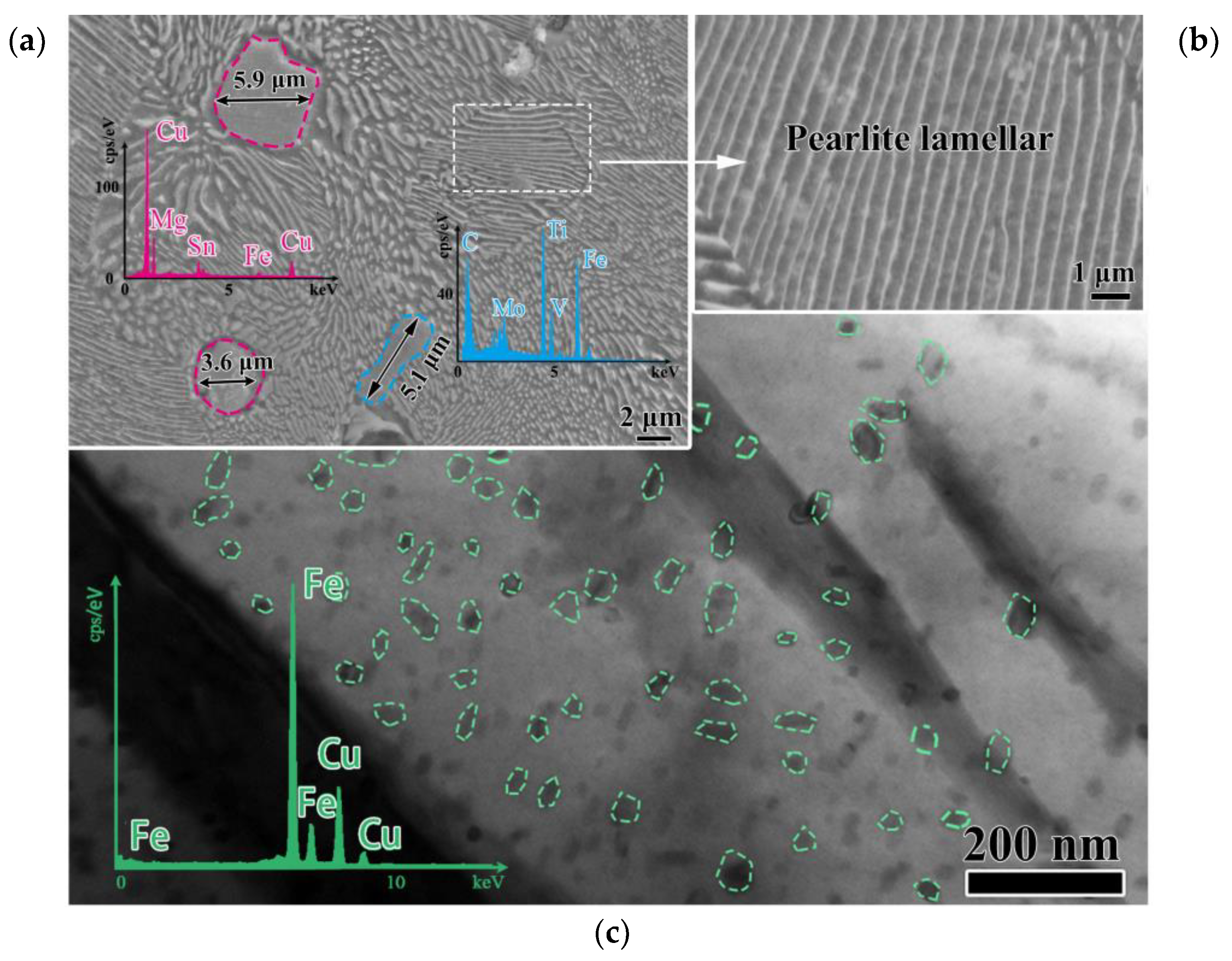
- The microstructure of SHF is tempered sorbite, the microstructure of SHG is pearlite, and the pearlite lamellar spacing is 0.57 μm. The main enhanced precipitated phase in the former is (Ti, V, Mo)/C and in the latter is Cu/Mg; both are the second-phase particles, which are larger than 1 μm in average length. The microstructure of 40Cr is tempered sorbite.
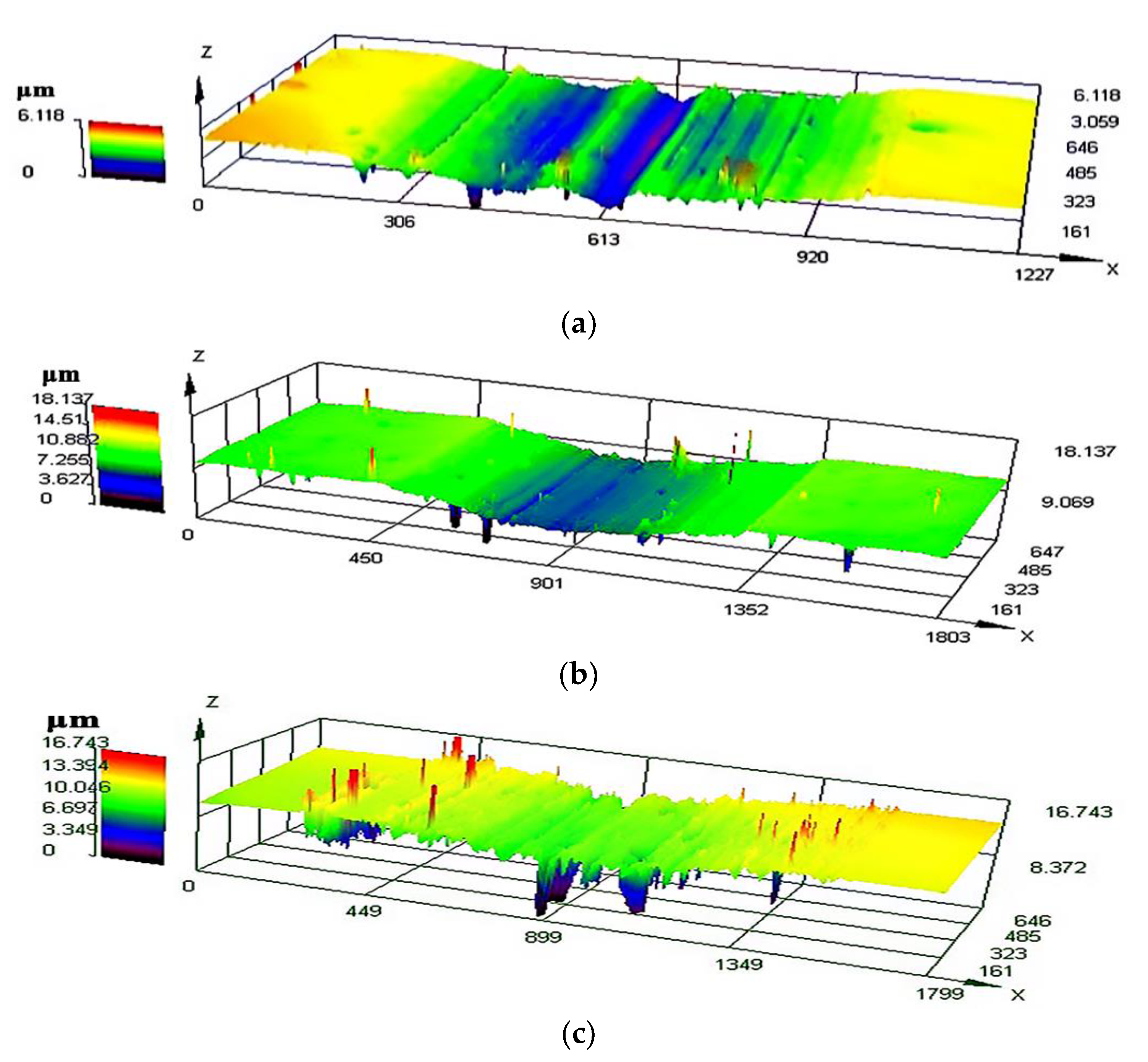
- Compared with 40Cr, ductile iron has better wear resistance, which is due to the existence of graphite that provides a solid self-lubrication layer. SHF has the lowest friction coefficient and wear followed by SHG, and the highest is 40Cr. The nodularity of the ductile iron of the two types of circular splines is well controlled, reaching more than 90%, and the obvious difference is mainly reflected in the area fraction and the diameter of the graphite nodules. The area fraction of the SHF graphite nodules is 8.58%, the area fraction of the SHG graphite nodules is 7.41%, and the average diameter of the graphite nodules is relatively thick, reaching 37.7 μm, while the average diameter of the SHG graphite nodules is 28.8 μm.
- The dominant wear mechanism of the SHF and SHG circular splines is abrasive wear, and the dominant wear mechanism of the 40Cr circular spline is adhesive wear. Hardness is not a key factor affecting the wear resistance of the materials. In this paper, the wear resistance is inversely proportional to the hardness, and the wear resistance of the two types of ductile iron depends on the different microstructures and second-phase particles. The area fraction of the SHF graphite nodules is 1.17% higher than that of the SHG graphite nodules, and the average diameter of the graphite nodules is 30.9% larger than that of the SHG graphite nodules. Both the diameter and the area fraction of the SHF graphite are large, the effective lubrication distance is longer, and more graphite was extruded to the wear surface, further improving the wear resistance. The wear resistance of the tempered sorbite with (Ti, V, Mo)/C as the main precipitation is stronger than that of the pearlite with Cu/Mg precipitation phase.
Author Contributions
Funding
Data Availability Statement
Conflicts of Interest
References
- Li, Y.; Tong, B.A.; Chen, W.B.; Li, X.Y.; Zhang, J.B.; Wang, G.X.; Zeng, T. Performance margin modeling and reliability analysis for harmonic reducer considering multi-source uncertainties and wear. IEEE ACCESS 2020, 8, 171021–171033. [Google Scholar] [CrossRef]
- Jian, L.Z.; Wei, Y. Failure Analysis of a flexspline of harmonic gear drive in STC industrial robot: Microstructure and stress distribution. IOP Conf. Ser. Mater. Sci. Eng. 2018, 452, 042148–042155. [Google Scholar]
- Gao, H.B.; Zhuang, H.C.; Li, Z.G.; Deng, Z.Q.; Ding, L.; Liu, Z. Optimization and experimental research on a new-type short cylindrical cup-shaped harmonic reducer. J. Cent. South Univ. 2012, 19, 1869–1882. [Google Scholar] [CrossRef]
- Zhang, C.L.; Shao, Z.H.; Zhu, Y.C.; Li, J. Austenite grain refinement and homogenization control of the flexspline for industrial robot harmonic drive. J. Mater. Eng. Perform. 2021, 30, 4393–4400. [Google Scholar] [CrossRef]
- International Federation of Robotics Home Page. Available online: https://ifr.org/ifr-press-releases/news/record-2.7-million-robots-work-in-factories-around-the-globe (accessed on 24 September 2020).
- Pham, A.D.; Ahn, H.J. High precision reducers for industrial robots driving 4th industrial revolution: State of arts, analysis, design, performance evaluation and perspective. Int. J. Precis. Eng. Manuf. Green Technol. 2018, 5, 519–533. [Google Scholar] [CrossRef]
- Qiang, L.G.; Xi, X.K.; Xiao, T.K.; Hou, J.P.; Qi, W.W.; Wang, K.N.; Qiang, L.G. Design and research of an electric shoulder joint harmonic reducer for a moving and lifting exoskeleton robot. J. King Saud Univ.—Eng. Sci. 2022, 34, 2–9. [Google Scholar] [CrossRef]
- Li, Y.F.; Zhang, Y.J.; Zhang, N.; Xu, B.C. Three-dimensional tooth profile design method of harmonic drive considering the deformation difference of the flexspline. Eng. Comput. 2021, 38, 3351–3367. [Google Scholar] [CrossRef]
- Zhang, C.X.; Song, Z.Q.; Liu, Z.F.; Cheng, Q.; Zhao, Y.S.; Yang, C.B.; Liu, M.M. Wear mechanism of flexspline materials regulated by novel amorphous/crystalline oxide form evolution at frictional interface. Tribol. Int. 2019, 135, 335–343. [Google Scholar] [CrossRef]
- Zhang, C.X.; Song, Z.Q.; Liu, Z.F.; Yang, C.B.; Cheng, Q.; Liu, M.M. Tribological properties of flexspline materials regulated by micro-metallographic structure. Tribol. Int. 2018, 127, 93–99. [Google Scholar] [CrossRef]
- Zhu, C.Z.; Wang, X.J.; Li, Z.L.; Liu, J.; Zheng, J.Q. Research on static and dynamics mechanical characteristics of flexible bearing in harmonic reducer. Int. J. Adv. Robot. Syst. 2020, 17, 172988142091995. [Google Scholar]
- Routh, B.; Maiti, R.; Ray, A.K. Analysis of coning and lubrication at flexspline cup and cam interface in conventional harmonic drives. Ind. Lubr. Tribol. 2017, 69, 817–827. [Google Scholar] [CrossRef]
- Sahoo, V.; Maiti, R. Evidence of secondary tooth contact in harmonic drive, with involute toothed gear pair, through experimental and finite element analyses of stresses in flex-gear cup. Proc. Inst. Mech. Eng. 2018, 232, 55–60. [Google Scholar] [CrossRef]
- Yang, C.B.; Hu, Q.S.; Liu, Z.F.; Zhao, Y.S.; Cheng, Q.; Zhang, C.X. Analysis of the partial axial load of a very thin-walled spur-gear (flexspline) of a harmonic drive. Int. J. Precis. Eng. Manuf. 2020, 21, 41–45. [Google Scholar] [CrossRef]
- Zhang, C.X.; Xu, C.X.; Liu, Z.F.; Liu, M.M.; Chu, H.Y.; Zhang, K.C. Formation of robust polydimethylsiloxane coatings on the flexspline material and mechanism of the tribological property improvement. Langmuir ACS J. Surf. Colloids 2022, 38, 10749–10759. [Google Scholar] [CrossRef]
- Li, Y.F.; Zhang, G.M.; Zhang, Y.J. Thermal–mechanical coupling deformation difference analysis for the flexspline of a harmonic drive. Rev. Adv. Mater. Sci. 2022, 61, 698–710. [Google Scholar] [CrossRef]
- Li, W.; Zhang, L.; Wu, C.; Cui, Z.; Niu, C. Influence of tool and workpiece properties on the wear of the counterparts in contact sliding. J. Tribol. 2022, 144, 1–24. [Google Scholar] [CrossRef]
- Tang, L.H.; Gao, C.X.; Huang, J.L.; Zhang, H.Y.; Chang, W.C. Dry sliding friction and wear behavior of hardened aisid2 tool steel with different hardness levels. Tribol. Int. 2013, 66, 165–173. [Google Scholar] [CrossRef]
- Zhang, Q.Y.; Wang, S.Q.; Li, X.X.; Zhou, Y.; Chen, K.M.; Cui, X.H. Relations of counterface hardness with wear behavior and tribo-oxide layer of aisi h13 steel. Metall Mater Trans. 2016, 47, 5960–5973. [Google Scholar] [CrossRef]
- Wang, R.; Wang, L.S.; Shi, T.; Zhou, C.; Wang, L.M. Study on friction and wear properties of P/M circular spline materials for harmonic reducer. Mater. Rev. 2012, 36, 188–194. (In Chinese) [Google Scholar]
- Haseeb, A.S.M.A.; Islam, M.A.; Bepari, M.M.A. Tribological behaviour of quenched and tempered, and austempered ductile iron at the same hardness level. Wear 2000, 244, 12–16. [Google Scholar] [CrossRef]
- Tong, L.; Zou, Q.; Jie, J.; Li, T.J.; Wang, Z.X. Wear behavior of ductile iron wheel material used for rail-transit vehicles under dry sliding conditions. Materials 2020, 13, 2683. [Google Scholar] [CrossRef]
- Ouyang, J.H.; Li, Y.F.; Zhang, Y.Z.; Wang, Y.M.; Wang, Y.J. High-temperature solid lubricants and self-lubricating composites, a critical review. Lubricants 2022, 10, 177. [Google Scholar] [CrossRef]
- Zhang, H.; Wu, Y.X.; Li, Q.J.; Hong, X. Effect of matrix structure on mechanical properties and dry rolling-sliding wear performance of alloyed ductile iron. J. Iron Steel Res. Int. 2019, 26, 62–69. [Google Scholar] [CrossRef]
- Patil, N.A.; Pedapati, S.R.; Marode, R.V. Wear analysis of friction stir processed AA7075-SiC-graphite hybrid surface composites. Lubricants 2022, 10, 267. [Google Scholar] [CrossRef]
- Hervas, I.; Bettaieb, M.B.; Thuault, A.; Eric, H. Graphite nodule morphology as an indicator of the local complex strain state in ductile cast iron. Mater. Des. 2013, 52, 39–43. [Google Scholar] [CrossRef]
- Wang, Z.Y.; Wan, W.C.; Wang, J.; Fan, K.Y.; Li, Y.H.; Xiong, J.; Du, H. Carburization and wear behavior of self-lubricating Ti(C,N)-based cermets with various secondary carbides. Ceram. Int. 2021, 47, 26678–26691. [Google Scholar] [CrossRef]
- Tiedje, N.S. Solidification, processing and properties of ductile cast iron. Mater. Sci. Technol. 2010, 26, 505–514. [Google Scholar] [CrossRef]
- Fraś, E.; Górny, M. Inoculation Effects of cast iron. Arch. Foundry Eng. 2012, 12, 39–46. [Google Scholar] [CrossRef]
- Konca, E.; Tur, K.; Koç, E. Effects of alloying elements (Mo, Ni, and Cu) on the austemperability of GGG-60 ductile cast iron. Metals 2017, 7, 320. [Google Scholar] [CrossRef]
- Hong, S.M.; Park, E.K.; Park, J.J.; Lee, M.K.; Lee, J.G. Effect of nano-sized TiC particle addition on microstructure and mechanical properties of SA-106B carbon steel. Mater. Sci. Eng. A 2015, 643, 37–46. [Google Scholar] [CrossRef]
- Aline, B.; Valérie, G.; Djar, O.; Jacques, L.; Henrique, S. The role of manganese and copper in the eutectoid transformation of spheroidal graphite cast iron. Metall. Mater. Trans. A 1997, 28, 2015–2025. [Google Scholar]
- Abedi, H.R.; Fareghi, A.; Saghafian, H.; Kheirandish, S.H. Sliding wear behavior of a ferritic–pearlitic ductile cast iron with different nodule count. Wear 2010, 268, 622–628. [Google Scholar] [CrossRef]
- Modi, O.P.; Mondal, D.P.; Prasad, B.K.; Singh, M.; Khaira, H.K. Abrasive wear behaviour of a high carbon steel: Effects of microstructure and experimental parameters and correlation with mechanical properties. Mater. Sci. Eng. A 2003, 343, 235–242. [Google Scholar] [CrossRef]


| Alloy Compositon | C | Si | Mn | P | S | Cr | Ni | Cu | Mo | Ti | Fe |
|---|---|---|---|---|---|---|---|---|---|---|---|
| SHF | 3.17 | 2.18 | 0.40 | 0.021 | 0.007 | 0.043 | 0.015 | 0.19 | 0.005 | 0.015 | Bal. |
| SHG | 3.44 | 2.00 | 0.41 | 0.019 | 0.006 | 0.02 | 0.011 | 2.63 | 0.002 | — | Bal. |
| 40Cr | 0.40 | 0.21 | 0.63 | 0.019 | 0.005 | 0.93 | 0.02 | — | — | — | Bal. |
Disclaimer/Publisher’s Note: The statements, opinions and data contained in all publications are solely those of the individual author(s) and contributor(s) and not of MDPI and/or the editor(s). MDPI and/or the editor(s) disclaim responsibility for any injury to people or property resulting from any ideas, methods, instructions or products referred to in the content. |
© 2023 by the authors. Licensee MDPI, Basel, Switzerland. This article is an open access article distributed under the terms and conditions of the Creative Commons Attribution (CC BY) license (https://creativecommons.org/licenses/by/4.0/).
Share and Cite
Hu, G.; Ge, Y.; Wu, T.; Mu, X.; Ren, F.; Shao, Z.; Zhang, C. Influence of Materials on Dry Friction and Wear Performance of Harmonic Reducer Circular Spline. Metals 2023, 13, 378. https://doi.org/10.3390/met13020378
Hu G, Ge Y, Wu T, Mu X, Ren F, Shao Z, Zhang C. Influence of Materials on Dry Friction and Wear Performance of Harmonic Reducer Circular Spline. Metals. 2023; 13(2):378. https://doi.org/10.3390/met13020378
Chicago/Turabian StyleHu, Guyue, Yi Ge, Tong Wu, Xiaobiao Mu, Fengyao Ren, Zhuhao Shao, and Chaolei Zhang. 2023. "Influence of Materials on Dry Friction and Wear Performance of Harmonic Reducer Circular Spline" Metals 13, no. 2: 378. https://doi.org/10.3390/met13020378