Article

Introduction of Coal Reinforcing Particles on the Dissimilar FSW AA608/AA5083 Joint via Friction Stir Processing

1
Mechanical and Mechatronic Engineering Department, Cape Peninsula University of Technology, Bellville 7535, South Africa
2
College of Science, Technology, and Engineering, Florida Campus, University of South Africa, Pretoria 0002, South Africa
*
Author to whom correspondence should be addressed.
Metals 2023, 13(12), 1981; https://doi.org/10.3390/met13121981
Submission received: 14 November 2023 / Revised: 30 November 2023 / Accepted: 4 December 2023 / Published: 6 December 2023
(This article belongs to the Special Issue Studies on Aeronautical Metals by Friction Stir Welding)

Abstract

:
This study investigates the mechanical characteristics of friction stir processed dissimilar joints between AA5083 and AA6082 alloys reinforced with coal particles. Employing friction stir welding (FSW), the mean grain size measured 19.7 μm, but using the FSP technique with coal reinforcement (FSP + Coal) significantly refined the grain size to 8.75 μm. In flexural testing, FSW face samples exhibited failure at 12.7% strain and 535 MPa stress, while FSP + Coal face specimens showed diminished performance at 3% strain and 222 MPa stress. Similar trends were observed in root specimens. For FSW joints, the ultimate tensile strength (UTS) peaked at 145.90 MPa, with the lowest recorded UTS at 93.43 MPa. FSP + Coal joints reached a maximum UTS at 142 MPa and minimum UTS at 104.06 MPa. Fractures in both FSWed and FSPed samples occurred on the AA5083 side. In terms of hardness, FSW joints exhibited 80.33 HV, while FSP + Coal joints displayed a higher hardness of 83.66 HV at the nugget zone. Fracture surface morphology analysis revealed a prominent ductile failure mechanism for both FSWed and FSP + Coal joints. This study provides insight into the enhanced mechanical properties achieved through FSP + Coal processing, offering valuable implications for dissimilar alloy joints in various applications.

1. Introduction

Friction stir processing (FSP) has emerged as a versatile solid-state joining and processing technique, holding significant promise for enhancing the mechanical properties of dissimilar metal joints [1,2]. In recent years, researchers have increasingly explored innovative methodologies to improve these joints through the integration of reinforcing agents. This incorporation of reinforcing agents via FSP into aluminum alloys is a fundamental component of the broader concept known as friction stir processing of advanced metal matrix composites (FSP AMMCs) [3,4]. These reinforcing agents can take the form of particles, fibers, or other materials, imparting added mechanical, thermal, or functional attributes to the base metal. In the context of aluminum alloys, FSP AMMCs entail introducing nanoparticles, ceramic particles, carbon-based materials, or other strengthening agents into the aluminum matrix [4,5]. The FSP process uniformly disperses these reinforcing agents throughout the material, leading to improved mechanical properties such as increased strength, enhanced wear resistance, and improved thermal stability.
The concept of FSP AMMCs has garnered attention due to their potential to combine the desirable traits of traditional alloys with the heightened performance of reinforcing particles. Early research on FSP AMMCs marked an innovative exploration into combining advanced materials processing with composite fabrication. Among the early contributors, Mishra et al. [6] shed light on enhancing metal properties through reinforcing agents. Their study examined the effect of augmenting AA5083 aluminum alloy with SiC particles, evaluating the effect of various SiC volume fractions and particle sizes on microhardness. Intriguingly, they found that the introduction of 27 vol% SiC with an average particle size of 0.7 μm significantly elevated microhardness. The alloy’s microhardness surged from 85 HV to an impressive 173 HV upon SiC inclusion. By meticulously analyzing the influence of SiC content and particle size on microhardness, Mishra et al. not only demonstrated the feasibility of reinforcing aluminum alloys but also underscored the profound impact on their mechanical attributes. This laid the foundation for subsequent research, prompting deeper explorations into matrix materials and the interplay with reinforcing agents.
Jian and Mishra [7] investigated the production of dissimilar composite joints by combining AA6061 and AA7075 alloys with micro-sized Al2O3 particles through friction stir welding. The distribution pattern of varying Al2O3 microparticle volume fractions was explored in conjunction with different combinations of tool rotational speed (RS) and traverse speed (TS), which influenced the quality of the welds. The composite joints underwent tensile, microhardness, and wear resistance testing, and were assessed for microstructural changes. The outcomes indicated that the weld quality significantly improved due to both higher grain refinement resulting from dynamic recrystallization (DRX) and the anchoring effect of Al2O3 microparticles. Additionally, an increase in the volume fraction of Al2O3 microparticles resulted in notable enhancements in the mechanical properties of the composite joints. Consequently, the composite joint processed at an RS of 1100 rpm, TS of 40 mm/min, and 10% volume fraction of Al2O3 microparticles exhibited the highest tensile strength at 241.35 MPa, with a joint efficiency of 83.80% and maximum microhardness recorded at 157.5 HV. Furthermore, the incorporation of Al2O3 microparticles also led to an improvement in the wear resistance of the composite joints compared to the base materials. This research shed light on the synergistic relationship between nanoparticle dispersion, microstructural refinement, and the resulting mechanical improvements, thereby offering valuable insight for future applications of this technique in tailoring material properties for enhanced performance.
In the study conducted by Acuña et al. [8], the focus was on investigating the use of FSP to produce surface metal matrix composites (SMMCs) for AA2024 aluminum alloy with structural hardening (T351) in a defect-free manner. The study primarily investigated how the number and direction of FSP passes affected particle distribution and microstructural changes in the processed region and their impact on the wear behavior of the composite layers. The results affirmed that FSP can create SMMCs with a well-distributed particle dispersion. By utilizing electron backscatter diffraction (EBSD), the researchers examined the evolution of grain size in different regions of the FSPed samples, revealing a significant reduction in grain size in the nugget zone due to dynamic recrystallization. The study also assessed surface properties through hardness and resistance to sliding wear tests. Although the SMMC hardness in the nugget was similar to that of the base material, it exhibited improved wear resistance. In the context of the sliding conditions examined in this study, the specific wear rate was notably reduced, ranging from 24 to 40% compared to the as-received aluminum alloy. Additionally, the worn tracks demonstrated the same wear mechanisms operating concurrently in both materials.
Malopheyev et al. [9] employed the FSP technique to produce an Al/Al203 composite in order to investigate the evolution of the microstructure. To gain a deeper understanding of this process, a cross-sectional analysis of the resulting composite was performed, and advanced characterization techniques such as electron backscatter diffraction and microhardness mapping were utilized. The study discovered that the reinforcing particles quickly arranged themselves into a stable “onion ring” structure, which remained intact even after subsequent dispersion. Specifically, remnants of relatively large particle clusters persisted even after 12 FSP passes. This led to the conclusion that the commonly employed three or four FSP passes in practice are insufficient for achieving uniform dispersion of reinforcing particles. Furthermore, it was observed that the gradual distribution of nanoscale Al2O3 particles within the aluminum matrix led to a subtle reduction in both the proportion of high-angle boundaries and the average grain size. These observations were attributed to the effect of particle pinning on grain boundary migration and dislocation slip.
FSP was employed to integrate multi-walled carbon nanotubes (MWCNTs) and nanoscale cerium oxide particles into the Al5083 alloy matrix, forming reinforced surface composites [10]. This study probed the influence of nanoscale reinforcements on the microstructure, mechanical properties, and corrosion resistance of FSP-treated Al5083 surface composites. The process employed a threaded cylindrical hardened steel tool, rotation speeds of 600 and 800 rpm, travel speeds of 35 and 45 mm/min, and a tilt angle of 5°. The findings highlighted that the hybrid composite with a 75–25 volume ratio of CNTs to cerium oxide exhibited the highest tensile strength and hardness values. Alternatively, incorporating cerium oxide alone significantly enhanced the base alloy’s pitting resistance. Corrosion behavior was systematically assessed through potentiodynamic polarization tests, focusing on pitting potential and passivation range.
Microstructural analysis, involving optical and electron microscopy, showed well-dispersed reinforcements in the nugget zone, accompanied by significant grain refinement. The study’s aim was to engineer surface composites with simultaneously enriched mechanical properties and corrosion resistance. The strategic inclusion of nanoscale reinforcements via FSP contributed to composite material advancement, showcasing the potential for multifunctional improvements in material performance. Subsequent to these pioneering studies, diverse literature has augmented the concept, encompassing a range of materials, including aluminum, magnesium, steel, copper, and titanium. The existing body of literature offers an array of reinforcing particles for FSP AMMC formulation, featuring boron carbide (B4C) [11], silicon carbide (SiC) [12], titanium carbide (TiC) [3], titanium dioxide (TiO2) [13], aluminum oxide (Al2O3) [14], titanium diboride (TiB2) [15], and zirconium diboride (ZrB2) [16].
Furthermore, the utilization of coal as a reinforcing agent has captured attention due to its distinctive combination of mechanical and thermal properties. The primary objective of this study was to comprehensively characterize dissimilar joints formed between AA5083-H111 and AA6082-T651 aluminum alloys specifically reinforced with coal particles through FSP. The aim was to investigate and understand the intricate microstructural changes and mechanical properties within the modified zones resulting from the combination of dissimilar alloys and the introduction of coal particles.
By delving into the detailed characterization of these joints, this research seeks to contribute valuable insight into the feasibility, structural integrity, and potential applications of such composite materials. AA5083 and AA6082 aluminum alloys are renowned for their amalgamation of strength, corrosion resistance, and formability, making them pivotal across industries [17]. However, when these alloys are conjoined, disparities in microstructure and mechanical properties can compromise joint integrity [18].
To overcome this challenge, researchers have turned to FSP as an innovative means to forge joints with enhanced mechanical attributes and refined microstructure. The inclusion of coal particles via FSP introduces a distinctive dimension to joint formation. Coal’s inherent strength and thermal resistance offer the potential to interact synergistically with the aluminum matrix, conferring added strength and durability to the joint. The outcomes of this research contribute to advancing dissimilar joint fabrication techniques while offering prospects for utilizing alternative materials to bolster mechanical robustness across diverse applications.

2. Materials and Methods

The study utilized AA6082-T651 and AA5083-H111 aluminum alloys, each possessing a thickness of 6 mm. The chemical compositions of the base materials were determined using a Belec Compact Spectrometer HLC manufactured by the Belec Spectrometry Opto-Electronics GmbH, Georgsmarienhütte, Germany. The resulting compositions are detailed in Table 1. Table 2 shows the mechanical properties of AA6082-T651 and AA5083-H111. 
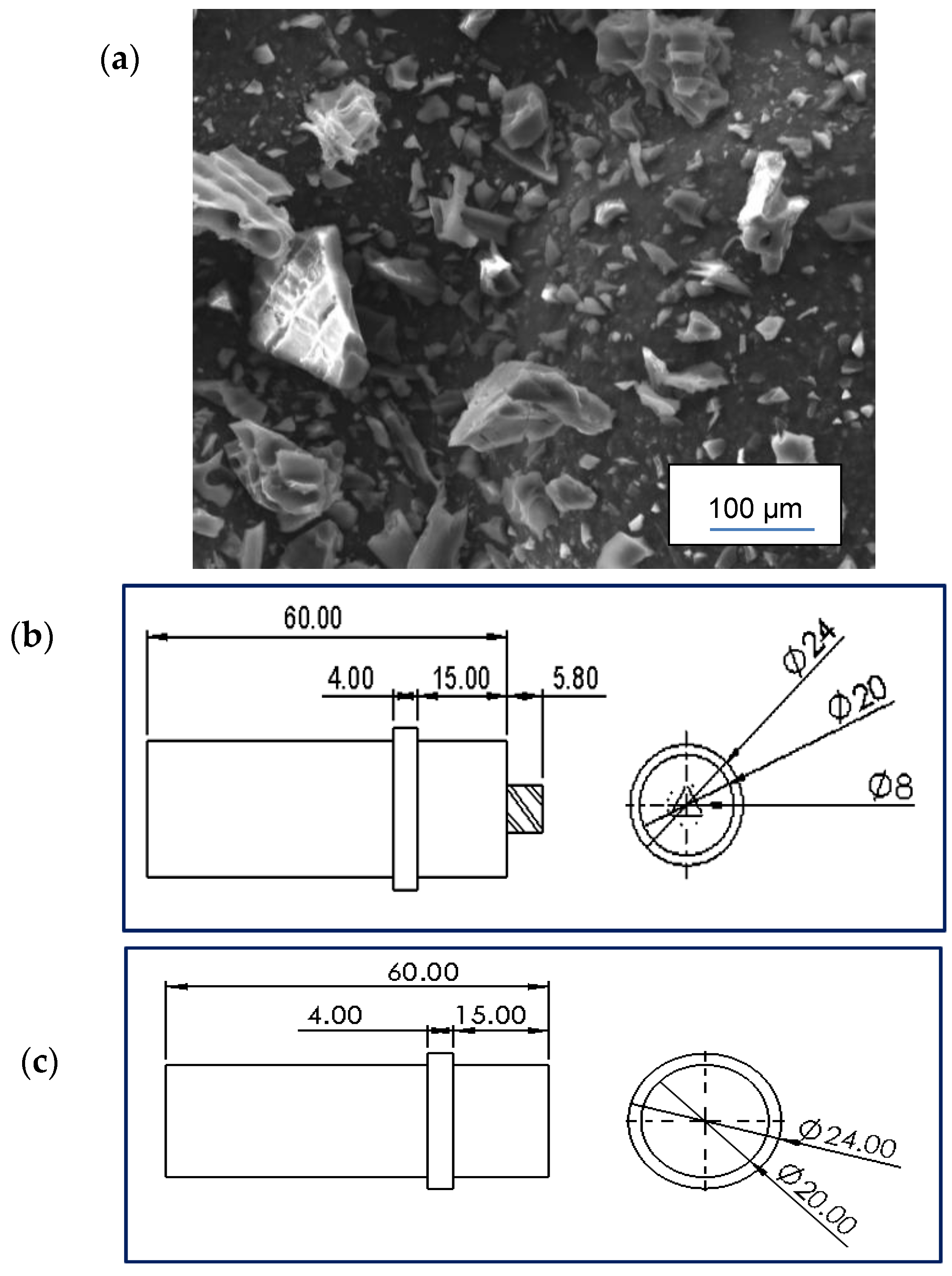
Figure 1a shows a SEM image of the coal powder, while Table 3 shows the chemical composition of the same. Subsequently, plates of dimensions 540 × 70 mm were cut from these alloys to fit within the FSW fixture bed. Employing the friction stir welding (FSW) technique, these dissimilar plates were skillfully joined. The FSW process was executed using a Lagun FU.1-LA universal milling machine manufactured by the Lagun Machine Tools S.L.U. in Gipuzkoa in Spain, which was adapted to function as an FSW machine. The specific FSW parameters applied are outlined in Table 4, with Figure 1b showing a Solidworks 2D diagram of the tool used. The tool was made of high-speed steel material.
During the FSW operation, the AA6082-T651 plate was positioned on the advancing side of the tool, while the AA5083-H111 plate was situated on the retreating side of the tool. Through this process, two friction stir welded (FSWed) plates were fabricated. One of these plates was preserved for comparative analysis, while the other underwent further treatment involving friction stir processing (FSP) with the inclusion of coal particle reinforcements. The incorporation of coal particles into the FSP procedure involved a sequential process carried out in four distinct stages. The initial step encompassed the drilling of blind holes at the center of the dissimilar weld joint generated through FSW, spanning from the initiation point to the termination point of the weld. These blind holes possessed a diameter of 2.5 mm and reached a depth of 5.6 mm. The spacing between the blind holes was consistently maintained at a distance of 5 mm. Subsequently, in the second phase, the blind holes were meticulously filled with coal particles until reaching their uppermost limit.
Advancing to the third step, the previously drilled holes were sealed utilizing a pinless tool configuration, as illustrated in Figure 1c. The final phase encompassed the execution of the FSP procedure, leveraging the same tool that had been employed for the FSW operation. The concept of utilizing a common tool design for both FSW and FSP is not uncommon and is frequently discussed in the broader body of literature concerning friction-based processing methodologies [19,20]. This adaptability of tools across the domains of FSW and FSP has been a subject of exploration and analysis in various studies focusing on friction-based material processing techniques.
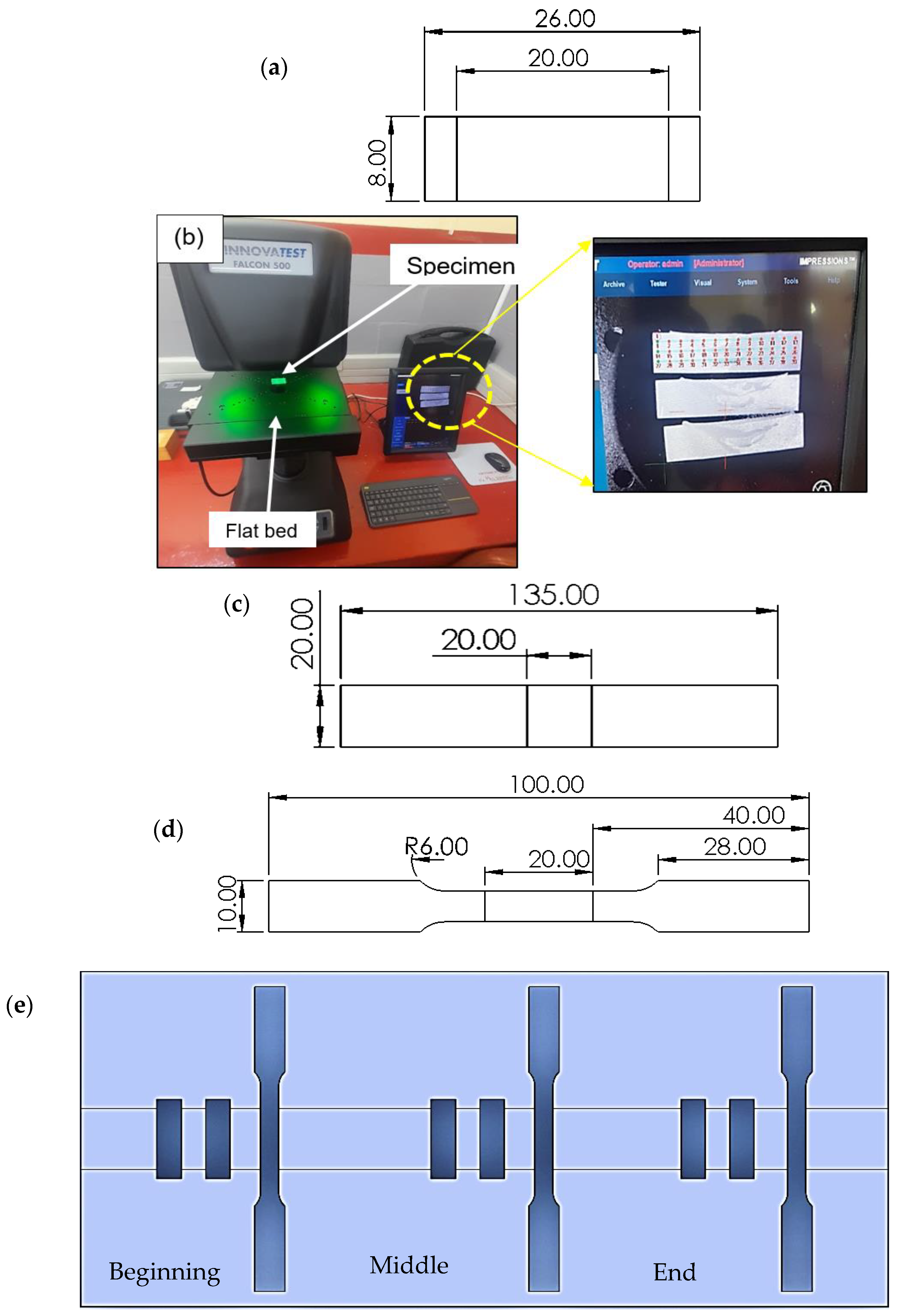
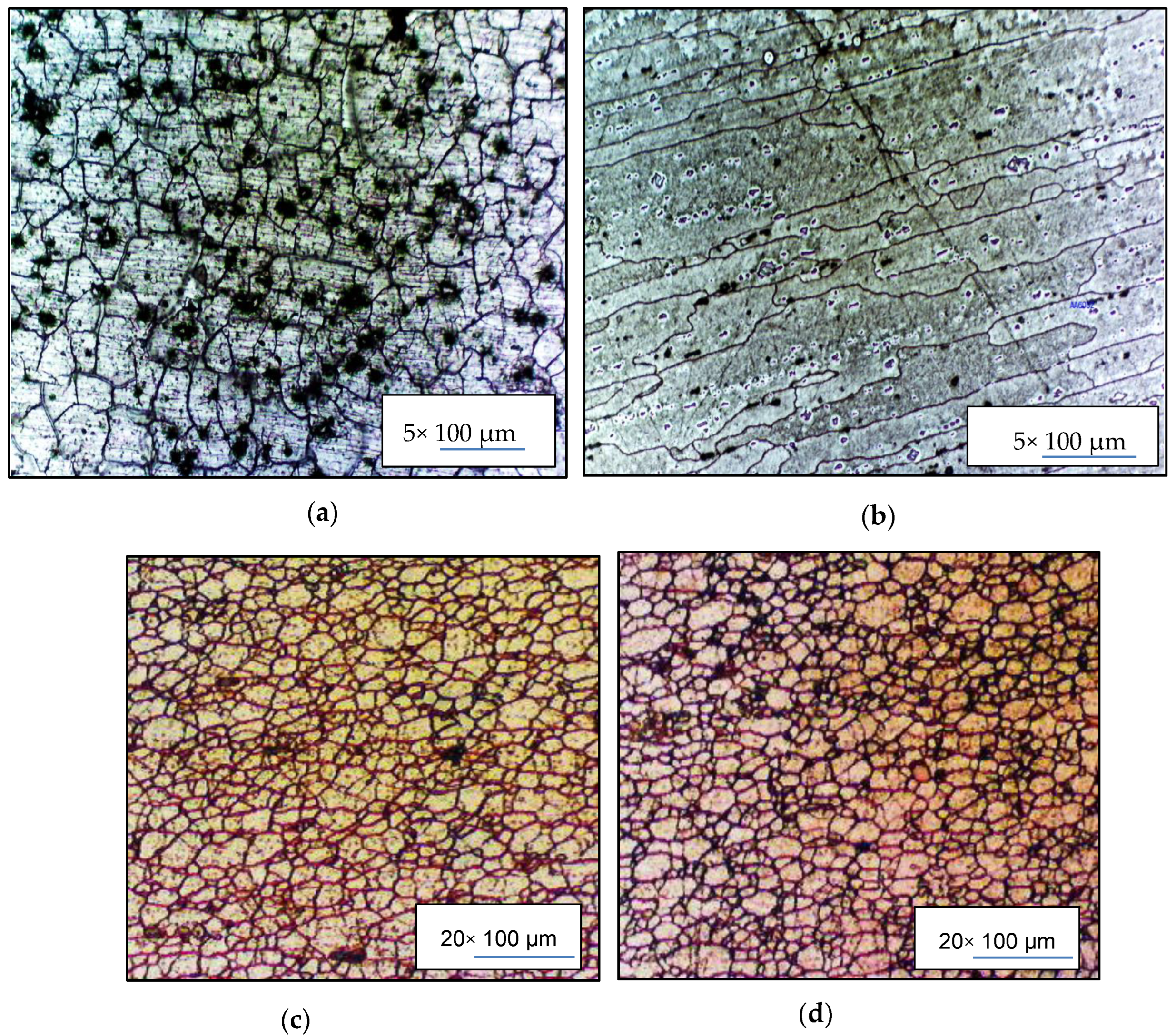
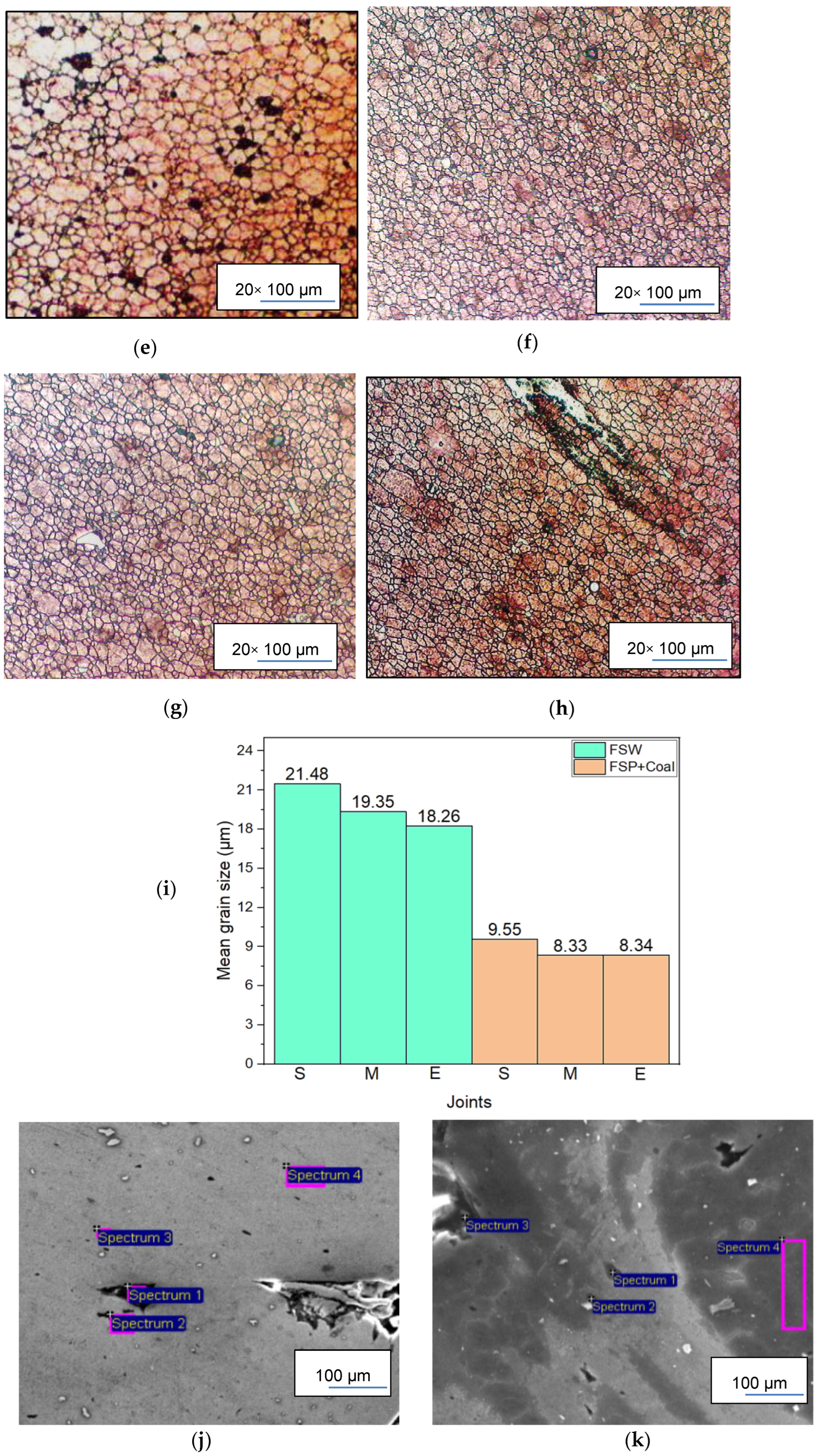
From the produced plates, microstructure, bending, tensile, and hardness test specimens were cut according to the respective ASTM standards. The microstructural analysis specimens were mounted in a thermosetting plastic, ground, polished, and etched. Keller’s etching solution was employed with 95 mL distilled water, 1.5 mL hydrochloric acid, 1 mL hydrofluoric acid, and 2.5 mL nitric acid. Figure 2a shows the specimen dimensions. After the etching process, the specimens were analyzed using the Motic AE2000MET, manufactured by The Motic Europe S.L.U. based in Barcelona in Canada. The micrographs obtained were measured following the ASTM E112-12 standard [21], using the line intercept method in ImageJ software to obtain the grain sizes. The same specimens were later subjected to hardness testing.
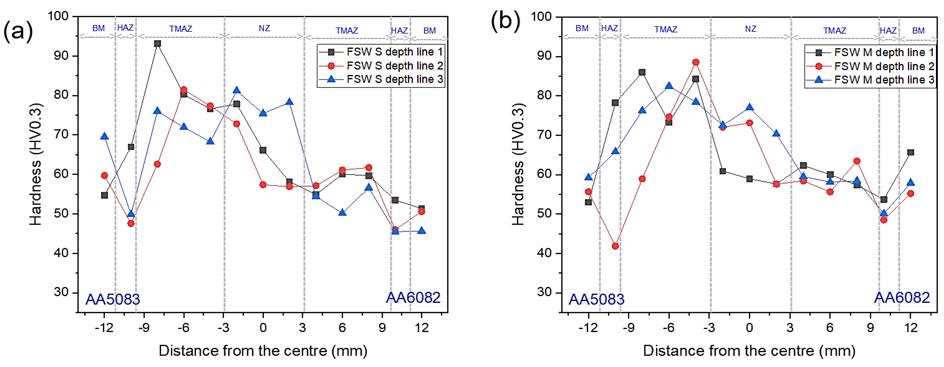
The InnovaTest Falcon 500 (manufactured by the INNOVATEST Europe BV Manufacturing based in Maastricht in the Netherlands) was used to perform hardness testing, following the ASTM E384-11 standard for microindentation hardness of materials [22]. The particular configuration comprised of a 0.3 kg load and 1 mm interval between indents, recording 25 measurement indents per joint. The 10× and 20× objectives were employed for specimen focusing. Figure 2b shows the setup for the hardness indentation testing. 
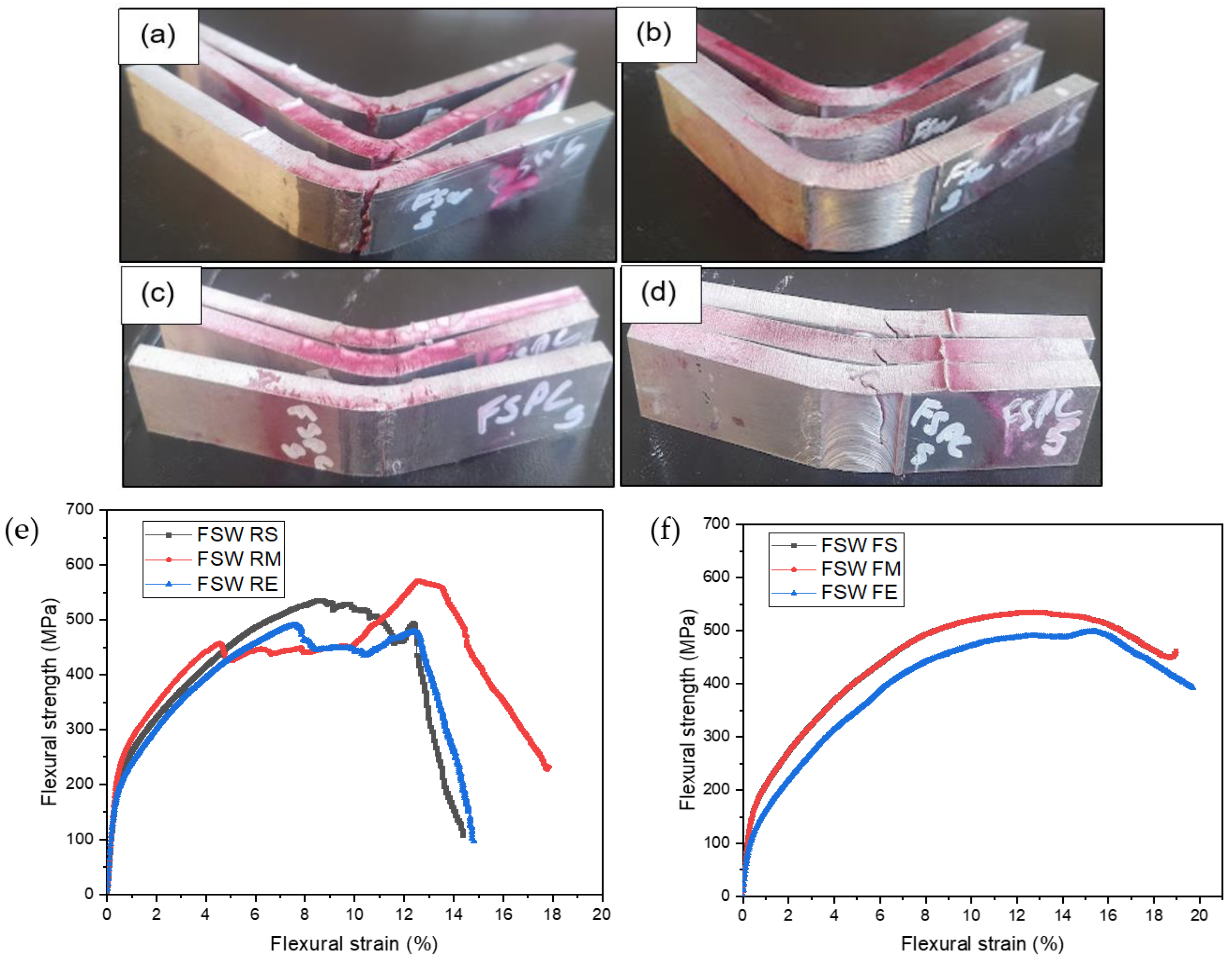
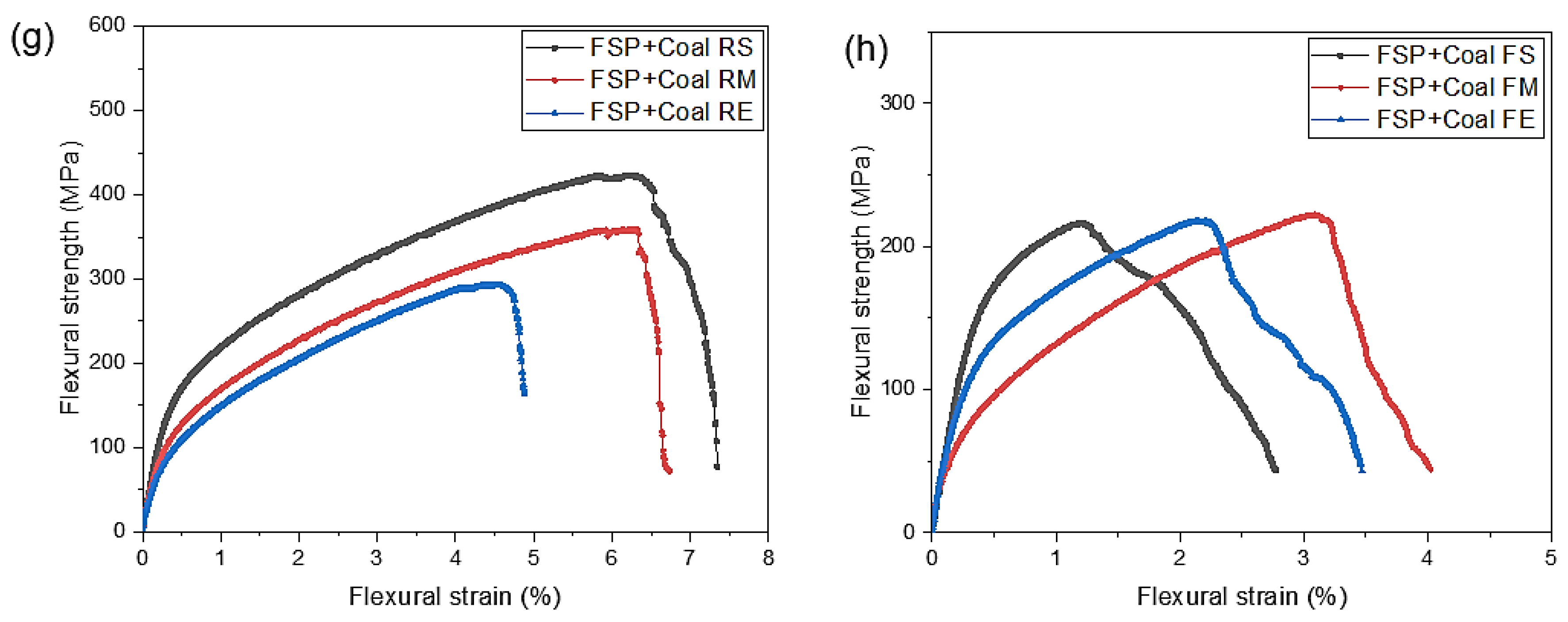
Figure 2c shows the flexural specimen with dimensions in mm. The testing procedures outlined in the ASTM E290-14 standard focus on assessing the ductility of materials through bend tests [23]. It should be noted that the bending test was applied to both sides of the joint, i.e., the face and root of each specimen. The face of the specimen is the surface in contact with the tool during welding, while the root is the surface in contact with the welding machine bed. Liquid penetrant testing (LPT), a form of non-destructive testing (NDT), was performed on the bent specimens to detect any potential defects on their surfaces after the test. Both flexural and tensile tests were executed using the Hounsfield 50 K machine. The tensile tests adhered to the guidelines set by the ASTM E8M-04 standard [24], which pertains to the tension testing of metallic materials. A depiction of the tensile test specimen can be seen in Figure 2d.
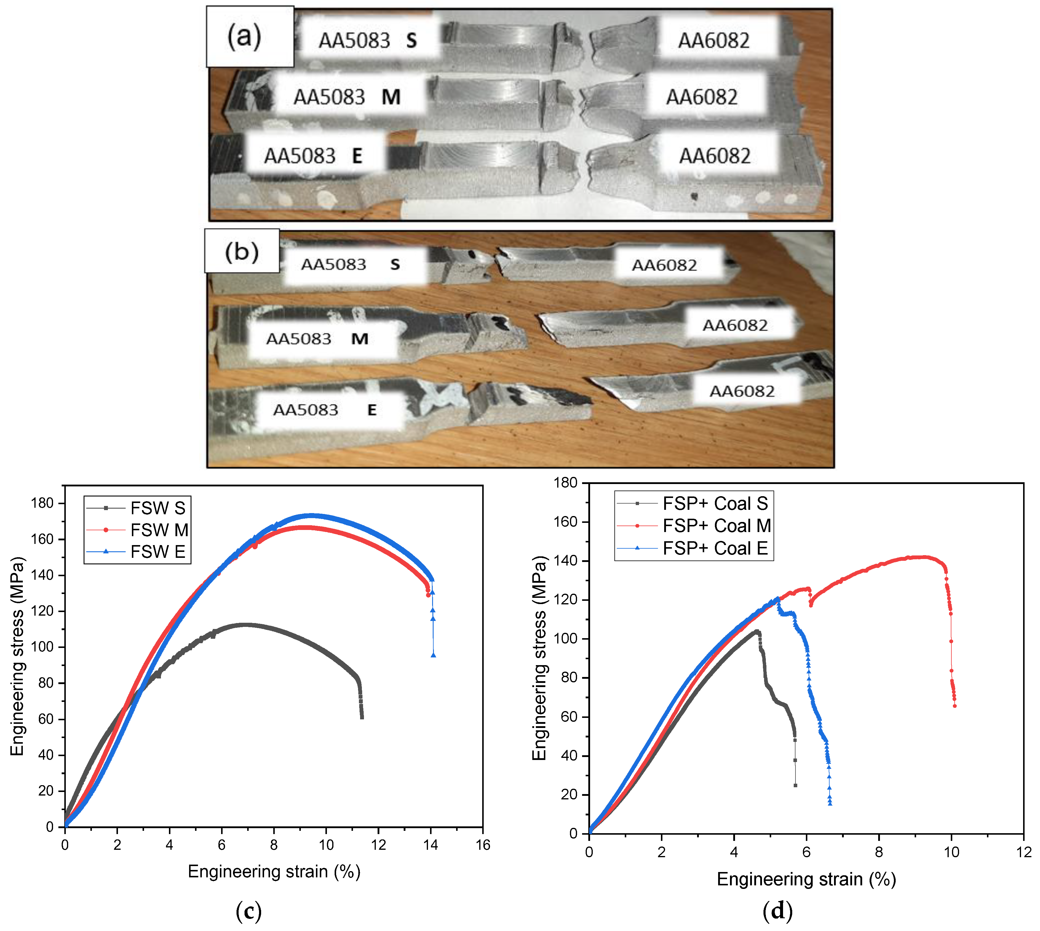
The test specimens derived from the dissimilar FSWed and FSP + Coal plates were systematically sectioned at three distinct positions along the welds: the beginning (S), middle (M), and end (E), as illustrated in Figure 2e. This procedure was implemented with the intention of discerning any potential patterns or trends associated with the sampling positions. Consistently applying this method across all conducted tests allowed for a comprehensive evaluation of the material’s characteristics and behavior.

3. Results and Discussions

3.1. Macrostructural Analysis

Figure 3 presents the macrographs of the FSWed and FSP + Coal joints, with each revealing distinct characteristics. For clarity, the microstructural zones in the macrographs are identified by red markings, with “1” representing the base metal (AA5083 and AA6082), “2” indicating the heat-affected zone, “3” denoting the thermomechanically affected zone, and “4” representing the NZ. These macrographs facilitate an understanding of the different regions and their corresponding properties within the joints.
In the case of FSWed joints shown in Figure 3a–c, the specimen extracted from the start of the joint displayed a small tunnel void, while the middle and end specimens exhibited a noticeable tunnel defect, identified by yellow circles. This tunnel defect, which became progressively more noticeable as the joint continued, can be ascribed to a fundamental issue during the early stages of joint formation. In particular, it is linked to an insufficiency in heat generation and consequently inadequate material flow [25,26]. These early stages are crucial in the FSW process, as they set the foundation for the integrity of the entire joint. When there is a deficiency in heat and material flow at this initial stage, it can lead to the formation of these tunnel defects, which compromise the structural integrity of the joint [27,28]. A noteworthy factor contributing to the observed disparity in behavior is the combination of dissimilar alloys with varying melting points, as the AA6082 and AA5083 alloys had melting points of 555 °C and 570 °C, respectively. These alloys had distinct properties, particularly in terms of their melting and softening characteristics. The AA6082 alloy exhibited a tendency to melt and soften more rapidly compared to the higher strength AA5083 alloy. This discrepancy in the behavior of the two alloys can further exacerbate challenges during the FSW process [17,29].
Figure 3d–f showcases the behavior of the FSP + Coal joints at different stages. The specimen extracted from the start showed no defects, indicating a well-mixed region where the AA6082 and AA5083 alloys were seamlessly integrated. This initial state reflects an ideal scenario in which the two alloys have successfully fused without the formation of any discernible defects [30]. However, as the joint progressed through the stages of FSP, the condition began to change such that for the specimen extracted in the middle of the joint, a tunnel defect became apparent in the nugget zone (NZ). This was a notable occurrence, and it suggested that as the processing continued, some challenges arose in maintaining the quality of the joint. The appearance of a tunnel defect at this stage was an indication of less-than-optimal material flow and heat distribution, as explained in Figure 3a–c. Moving to the specimen extracted at the end of the joint, a similar trend was observed, albeit to a lesser extent. In this specimen, a small defect in the nugget zone was noted. While this defect may have been less severe than the one in the middle specimen, it still indicated that the challenges in maintaining a defect-free joint persisted as FSP + Coal progressed.

3.2. Microstructural Analysis

Figure 4 shows the micrographs of the parent materials and FSWed and FSP + Coal joints. AA5083-H111, as depicted in the micrograph in Figure 4a, exhibited uniform and relatively coarse grain sizes along and across the rolling direction, with a mean grain size of 292 μm. The AA6082-T651 parent material (PM), shown in Figure 4b, displayed an average grain size of 389 μm along the rolling direction and only 117 μm across the rolling direction, thus exhibiting columnar grains. Dark spots of intermetallic particles were found in the micrographs of both AA6082-T651 and AA5083-H111 parent materials. For AA6082-T651, the dark spots in the microstructure indicated small particles of Mg2Si (magnesium silicide), which was the strengthening precipitate of the alloy [31]. These precipitates form within the aluminum matrix during the artificial aging process after solution heat treatment and quenching. The presence of Mg2Si particles in the microstructure contributes to the alloy’s strength and other mechanical properties, making it a common feature in heat-treatable aluminum alloys like AA6082-T651. These precipitates act as barriers to dislocation movement, thus enhancing the material’s strength [31,32]. In AA5083-H111, it is worth noting that the alloy has 5 precipitates: Al6(FeMn), Al3Mg2, Al6(Fe, Mn)Cr, Al6(FeMn)Si, and Mg2Si [32]. This therefore means that the dark sports represented some or all of the mentioned precipitates.
Figure 4c–h shows the NZ micrographs of the FSW and FSP + Coal joints at different specimen locations and positions, with Figure 4i showing the measured mean grain sizes of the same. The FSWed joints in Figure 4c–e displayed a fully recrystallized grain structure with distinct boundary layers, leading to a substantial reduction in grain size in comparison to the PMs. This was due to the intense plastic deformation and recrystallization that occur during FSW, breaking down the existing larger grains into smaller, more refined grains. A finer grain structure can lead to improved mechanical properties, such as increased strength and toughness, in the welded joint [33]. Few pores and impurities were noted in the micrographs, as well as a strengthening of precipitates in the form of black spots and stone-like particles, respectively. The presence of black spots indicated areas where inclusions or impurities were concentrated [31].
Figure 4f–h shows the FSP + Coal micrographs in which significantly high grain refinement was observed. This behavior was due to the unique combination of mechanical stirring and coal reinforcement. In this process, the mechanical action of the rotating tool and the addition of coal particles lead to intense plastic deformation and recrystallization in the joint region, breaking down larger grains and promoting the formation of a finer and more homogenous microstructure, ultimately enhancing the mechanical properties of the joint, including increased strength and toughness [33,34,35]. The visual comparison is evident in the bar charts provided in Figure 4i.
Figure 4j,k display the results of the energy-dispersive X-ray spectroscopy (EDS) analysis of both the FSWed and FSP + Coal samples, showcasing the analyzed spectra within the nugget zone. This analysis was undertaken to ascertain the presence of chemical segregation information, particularly focusing on the distribution of carbon within the intricate stirred nugget zone. The objective was to gain insight into the chemical composition and dispersion of carbon in this region.
Furthermore, Table 5 and Table 6 present the detailed chemical composition of the aforementioned joints in correlation with Figure 4j,k. These tables provide a comprehensive breakdown of the elemental composition, with a specific emphasis on carbon distribution within the nugget zone.

3.3. Flexural Properties

Figure 5a–d features the specimens after the flexural test. The flexing of the FSW face weld specimens toward the AA6082 side, which was the alloy with weaker strength, indicated that the FSW face weld joints possessed a higher joint strength than the base material, AA6082. This outcome aligned with prior research findings [36,37,38] and suggested that the welding process improved the overall mechanical properties of the joint, surpassing the inherent strength of AA6082. Remarkably, post-face specimens did not reveal any cracks except for the FSW E face weld specimen, which exhibited a minor defect crack at the edge of the TMAZ, coinciding with the bending end of AA6082 in the weld. In contrast, the root weld specimens uniformly exhibited cracks, predominantly occurring near or within the central region of the root weld, signifying a difference in the mechanical behavior between the face and root welds, and potentially highlighting the need for further investigation or adjustments in the welding process to enhance root weld strength.
In the case of FSP + Coal face weld specimens, the presence of cracks exclusively on the AA5083 TMAZ side could be attributed to the influence of the coal powder within the joint. The dominant presence of coal powder in this region seems to have played a critical role in crack formation [37]. Conversely, in the FSP + Coal root weld specimens, cracks were observed on the side where AA5083 was positioned as the advancing material during the welding process. This crack occurrence could be attributed to a thin layer of material that was intentionally not penetrated by the tool during welding to prevent the tool pin from rubbing against the back plate, possibly leading to localized stress concentrations and crack initiation in this specific area of the root weld.
Figure 5e–h presents the results of the flexural tests conducted on the root and face of the FSWed and FSP + Coal joints. It is essential to emphasize that all specimens were bent until failure, which explains the projectile shape evident in the graphs. The root flexural test outcomes indicated that the FSWed specimens failed at a maximum strain of 12.67% with a flexural stress of 571 MPa, while the FSP + Coal root specimens failed at a maximum strain of 6.2% with a flexural stress of 422 MPa. The face flexural test revealed different results: the FSWed specimens failed at a maximum strain of 12.7% with flexural stress of 535 MPa, whereas the FSP + Coal specimens failed at a maximum strain of 3% with a flexural stress of 222 MPa. The six graphs clearly highlight the distinctions between the face and root flexural tests for the FSWed and FSP + Coal specimens.
The data analysis unequivocally demonstrated that the flexural strength of the FSWed joints surpassed that of the FSP + Coal joints. This notable discrepancy in strength can be attributed to a combination of factors, with microstructure and the presence of defects being paramount among them. In the case of FSP + Coal joints, the uneven distribution of coal particles within the joints was a key contributing factor to this observed difference in mechanical properties. This non-uniform distribution of reinforcement materials can lead to irregularities in the structure and properties of the joint, resulting in localized weak points or areas with reduced mechanical integrity. Consequently, these variations undermined the overall flexural strength of the FSP + Coal joints, in line with previous research findings [39,40,41] highlighting the sensitivity of joint performance to the uniformity and distribution of reinforcement materials.

3.4. Tensile Properties

Figure 6a,b displays the post-tensile specimens of the FSWed and FSP + Coal joints. These specimens were subjected to tensile testing to evaluate their mechanical properties and behavior under tension. The FSWed specimens failed outside the welded area, specifically in the HAZ of the AA6082 side. This fracture pattern indicated a seamless joint, with the joint itself remaining intact during the test [20]. Additionally, the FSWed joints exhibited stronger characteristics than the base material, AA6082. The HAZ, however, demonstrated the weakest strength when compared to NZ and the AA6082 side of the specimen [42], which is a common phenomenon when dissimilar materials are joined together. On the other hand, the FSP + Coal joints exhibited a different failure pattern. The failure occurred within the welding zone area, close to the AA5083 side of the specimen, which appeared to be brittle in nature. The type of failure observed at the TMAZ indicated a lack of elongation or ductility, signifying a brittle failure [43].
This brittle failure in the FSP + Coal joints implied that the coal powder material significantly influenced the joints, leading to failure within the welded area where the coal powder was incorporated, as shown in Figure 6d. The location of the failure varied between specimens, occurring where the coal powder was present. One notable example is Specimen E, which displayed incomplete fusion between the coal powder and the alloy, potentially contributing to the brittle nature of the joint. Overall, the FSWed joints demonstrated seamless characteristics and superior strength compared to the base material, whereas the FSP + Coal joints exhibited brittle failure, influenced significantly by the presence and fusion of the coal powder [42,43].
Figure 6c,d shows the tensile stress–strain curves of the FSWed and FSP + Coal joints. The corresponding tensile properties are summarized in Table 7. Comparing the FSWed and FSP + Coal joints, the FSWed joints exhibited the highest UTS values while the FSP + Coal joints showed the lowest UTS values. Coal, being less mechanically robust than the base materials, seemed not to provide the same level of strength as witnessed in the original FSWed joints [44,45]. The integration of coal reinforcement led to voids, inclusions, and possibly weaker bonding at the interface between the reinforcement and the base material, resulting in a reduction in overall joint strength. Thus, the FSP + Coal joints exhibiting lower UTS values than the FSWed joints was not a startling result.

3.5. Fractography

Figure 7 illustrates the fracture surface morphology of the FSWed and FSP + Coal joints, providing insight into their respective failure mechanisms. Worthy of note was the location of fractures: FSWed joints displayed fractures primarily on the AA5083-H111 side, while the FSP + Coal joints exhibited failure on the AA6082-T651 side. This indicated a variation in failure behavior resulting from different welding methods and reinforcement strategies [46]. The fractures exhibited a distinctive ductile nature, evident from the abundant presence of circular dimples (denoted by dotted yellow circles) with varying sizes [35,46,47]. These dimples are typically due to plastic deformation and material flow during fracture. Furthermore, trans-granular cleavage facets (red arrows) were observed, signifying a type of brittle fracture within the material’s grains. This suggested that although the fractures were predominantly ductile, some localized areas experienced brittle failure, possibly due to variations in microstructural properties [48,49].
The fracture surface also displayed grain boundaries noted by a green arrow, which could have played a role in causing the fracture behavior. These boundaries may act as preferential paths for crack propagation, impacting the overall fracture resistance of the joints [20,49]. Inclusion particles, indicated by the white arrows, were observable on the fracture surface, potentially contributing to stress concentrations and influencing crack initiation and propagation. [50]. Lastly, microvoids, marked by the blue arrows, were observed as small voids or cavities within the fracture surface, further underlining the ductile characteristics of the fractures [47,48,49,50].

3.6. Microhardness

Figure 8 illustrates the Vickers hardness profiles of the welded joints produced through FSW and FSP + Coal with Table 6 showing the NZ average hardness of the same. One of the key findings was that AA5083-H111 consistently exhibited higher hardness values than AA6082-T651 in all of the tests conducted. This was due to AA5083-H111 and AA6082-T651 being two different aluminum alloys with distinct compositions, as previously mentioned in the materials and methods section. Differences in alloy composition can lead to variations in their respective mechanical properties, including hardness [17,35]. Also, the “-H111” and “-T651” designations represent different heat treatment conditions. AA5083-H111 was strain-hardened, also known as cold-worked and annealed, to achieve its specific hardness and mechanical properties [51]. In contrast, AA6082-T651 was heat-treated and artificially aged (solution heat-treated and then aged), which resulted in its hardness characteristics [19,52].
The FSWed and FSP + Coal joints displayed notably greater hardness than AA6082-T651 at the nugget zone, with an average value of 55–75 HV observed throughout the weld positions in FSW, as depicted in Figure 8a–c. However, moving away from the nugget zone towards AA6082-T651, the hardness values decreased across all of the welded joints. Interestingly, the tool shoulder and tool pin positions on the AA5083-H111 edges showed minimal differences in hardness values compared to the nugget zones, particularly at the start and middle weld positions. Moreover, at the end of the weld, greater hardness values were observed on the tool shoulder edges than in the nugget zone. On the AA6082-T651 side, the regions near the tool pin and tool shoulder positions registered relatively lower hardness values than other regions. In contrast, the nugget zone exhibited a significant increase in hardness values along the entire length of the welded joint, surpassing the hardness of the AA6082-T651 HAZ side. This increase in hardness was attributed to the fine grain size generated by the FSW process and the work-hardening effect induced during welding, as previously noted [47]. It is important to remember that the AA6082-T651 alloy was precipitate-hardened, and its properties can be greatly affected by temperatures above 200 °C [17,20,35].
Figure 8d–f shows the hardness profiles for the FSP + Coal welded joints. Interestingly, for all three positions (S, M, and E), the hardness values of AA5083-H111 at the tool shoulder edges exhibited minimal difference from those at the nugget zones. The maximum hardness value in the nugget zone was 84 HV. Additionally, all three welded depth lines were closely grouped together as they progressed from AA5083-H111 through the nugget zone to the AA6082-T651 side, in contrast to the FSW depth lines. To give a clear presentation of the NZ of the joints discussed, Table 8 provides all of the NZ hardness values. The higher hardness observed in FSP + Coal joints compared to FSW joints can be attributed to the influence of coal particles as reinforcing agents within the joint. During FSP, coal powder is incorporated into the joint, serving as a strengthening component. The presence of these coal particles within the joint can create a composite-like structure, resulting in increased hardness due to the reinforcement effect [45]. In contrast, in traditional FSW, where there is no deliberate introduction of reinforcing agents like coal, the microstructure and properties of the joint rely solely on the base materials, potentially resulting in lower hardness values. The addition of coal powder in FSP + Coal joints enhanced the hardness by providing additional strength and resistance to deformation, effectively improving the overall mechanical properties of the joint [53,54].

4. Conclusions

The primary objective of this study was to assess the mechanical characteristics of friction stir processed dissimilar joints between AA5083 and AA6082 alloys reinforced with coal particles. The conclusions of the study based on the results obtained can be drawn as follows:
  • The average mean grain size in the FSWed joints was 19.70 μm. Interestingly, the FSP + Coal method, which involved partial reinforcement with coal powder, resulted in an even more substantial mean grain refinement of 8.75 μm. This refinement was attributed to the introduction of coal particles acting as nucleation sites during processing, facilitating a more uniform distribution of fine grains throughout the microstructure.
  • The results from the flexural tests showed that the root specimens produced by FSW failed at a maximum strain of 12.67% and flexural stress of 571 MPa. In contrast, the root specimens manufactured through FSP + Coal failed at a lower maximum strain of 6.20% and reduced flexural stress of 422 MPa. The face specimens obtained through FSW failed at a maximum strain of 12.70% and flexural stress of 535 MPa. Lastly, the FSP + Coal specimens failed at a significantly lower maximum strain of 3% and much lower flexural stress of 222 MPa. The significant reduction in both maximum strain and flexural stress in FSP + Coal specimens was linked to factors such as inhomogeneous particle distribution, weak particle–matrix interfaces, and suboptimal processing parameters.
  • In the FSWed joints, the maximum UTS reached 145.9 MPa at a tensile strain rate of 9.43%, whereas the minimum UTS of the same joints was 93.43 MPa at a tensile rate of 7.02%. On the other hand, the FSP + Coal joints exhibited a maximum UTS of 142 MPa at a tensile strain rate of 9.28%, while the minimum UTS was 104.06 MPa at a tensile rate of 4.63%. Notably, the introduction of coal particle reinforcement led to a reduction in the UTS compared to FSWed joints, indicating a trade-off between the presence of coal particles and tensile properties. It is worth noting that the FSP + Coal method had a positive impact on the properties of the AA6082-T651 material, despite the reduction in UTS.
  • In the hardness test results, the FSP + Coal joints achieved the highest hardness value of 83.66 HV at the nugget zone, while FSW had a high hardness of 80.33 HV. The differences in the hardness of the joints can be attributed to the absence of the additional strengthening and grain refining effects observed in the FSP + Coal joints.
  • The fracture surface morphology analysis revealed a prominent ductile failure mechanism in the FSWed and FSP + Coal joints. The distinct features observed on the fracture surfaces provided valuable information about the localized deformation and fracture behavior within the joints.
In summary, the introduction of coal particles during FSP resulted in a refined microstructure, superior mechanical properties, and increased hardness at the nugget zone in comparison to FSW and standard FSP joints. However, the choice of reinforcement strategy should take into account the specific requirements of the application, as the presence of coal particles may lead to trade-offs in certain mechanical properties. Overall, the findings provided valuable insight into how to optimize the FSP process for dissimilar joints while highlighting the potential benefits of using coal as a reinforcement for FSP joints in materials processing, welding, and engineering applications. Leveraging the knowledge gained herein can result in the enhanced performance and reliability of welded joints, leading to improved products and technologies.

Author Contributions

Conceptualization, V.M. and S.M.; methodology, K.Z.; software, V.M.; validation, S.M., V.M. and K.Z.; formal analysis, K.Z.; investigation, K.Z.; resources, S.M.; data curation, S.M.; writing—original draft preparation, K.Z.; writing—review and editing, S.M.; visualization, V.M.; supervision, S.M.; project administration, V.M.; funding acquisition, S.M. All authors have read and agreed to the published version of the manuscript.

Funding

This research was funded by the SOUTH AFRICAN NATIONAL RESEARCH FOUNDATION—THUTHUKA Grant number 138268.

Data Availability Statement

Acknowledgments

The authors would like to thank the Cape Peninsula University of Technology, Department of Mechanical and Mechatronic Engineering workshop staff for their sincere support during the fabrication of the joints and Miranda Waldron from the University of Cape Town for assistance with the SEM tests.

Conflicts of Interest

The authors declare no conflict of interest.

References

  1. Mishra, R.S.; Ma, Z.Y. Friction stir welding and processing. Mater. Sci. Eng. R Rep. 2005, 50, 1–78. [Google Scholar] [CrossRef]
  2. Mabuwa, S.; Msomi, V.; Ndube-Tsolekile, N.; Zungu, V.M. Status and progress on fabricating automotive-based aluminium metal matrix composites using FSP technique. Mater. Today Proc. 2022, 56, 1648–1652. [Google Scholar] [CrossRef]
  3. Thangarasu, A.; Murugan, N.; Dinaharan, I.; Vijay, S.J. Microstructure and microhardness of AA1050/TiC surface composite fabricated using friction stir processing. Sadhana–Acad. Proc. Eng. Sci. 2012, 37, 579–586. [Google Scholar] [CrossRef]
  4. Moreira, F.; Ferreira, M.; Silva, R.J.C.; Santos, T.G.; Vidal, C. Aluminium-Based Dissimilar Alloys Surface Composites Reinforced with Functional Microparticles Produced by Upward Friction Stir Processing. Coatings 2023, 13, 962. [Google Scholar] [CrossRef]
  5. Pariyar, A.; Perugu, C.S.; Toth, L.S.; Kailas, S.V. Microstructure and mechanical behavior of polymer-derived in-situ ceramic reinforced lightweight aluminum matrix composite. J. Alloys Compd. 2021, 880, e160430. [Google Scholar] [CrossRef]
  6. Mishra, R.S.; Ma, Z.Y.; Charit, I. Friction stir processing: A novel technique for fabrication of surface composite. Mater. Sci. Eng. A 2003, 341, 307–310. [Google Scholar] [CrossRef]
  7. Jain, S.; Mishra, R. Influence of micro-sized Al2O3 particles on microstructure, mechanical, and wear behavior of dissimilar composite joint of AA6061/AA7075 by friction stir processing/welding. Proc. Inst. Mech. Eng. Part C J. Mech. Eng. Sci. 2022, 236, 9047–9060. [Google Scholar] [CrossRef]
  8. Acuna, R.; Cristóbal, M.J.; Abreu, C.M.; Cabeza, C. Microstructure and wear properties of surface composite layer produced by friction stir processing (FSP) in AA2024-T351 aluminum alloy. Metall. Mater. Trans. A 2019, 50, 2860–2874. [Google Scholar] [CrossRef]
  9. Malopheyev, S.S.; Zuiko, I.S.; Mironov, S.Y.; Kaibyshev, R.O. Microstructural Aspects of the Fabrication of Al/Al2O3 Composite by Friction Stir Processing. Materials 2023, 6, 2898. [Google Scholar] [CrossRef]
  10. Hosseini, S.A.; Ranjbar, K.; Dehmolaei, R.; Amirani, A.R. Fabrication of Al5083 surface composites reinforced by CNTs and cerium oxide nano particles via friction stir processing. J. Alloys Compd. 2015, 622, 725–733. [Google Scholar] [CrossRef]
  11. Zhao, Y.; Huang, X.Y.; Li, Q.; Huang, J.; Yan, K. Effect of friction stir processing with B4C particles on the microstructure and mechanical properties of 6061 aluminium alloy. Int. J. Adv. Manuf. Technol. 2015, 78, 1437–1443. [Google Scholar] [CrossRef]
  12. El-Mahallawy, N.A.; Zoalfakar, S.H.; Abdel Ghaffar Abdel Maboud, A. Microstructure investigation, mechanical properties and wear behavior of Al 1050/SiC composites fabricated by friction stir processing (FSP). Mater. Res. Express 2019, 6, e096522. [Google Scholar] [CrossRef]
  13. Kumar, K.A.; Natarajan, S.; Duraiselvam, M.; Ramachandra, S. Synthesis, characterization and mechanical behavior of Al 3003-TiO2 surface composites through friction stir processing. Mater. Manuf. Process. 2019, 34, 183–191. [Google Scholar] [CrossRef]
  14. Bourkhani, R.D.; Eivani, A.R.; Nateghi, H.R. Through-thickness inhomogeneity in microstructure and tensile properties and tribological performance of friction stir processed AA1050-Al2O3 nanocomposite. Compos. B Eng. 2019, 174, e107061. [Google Scholar] [CrossRef]
  15. Ma, S.M.; Zhang, P.; Ji, G.; Chen, Z.; Sun, G.A.; Zhong, S.Y. Microstructure and mechanical properties of friction stir processed Al-Mg-Si alloys dispersion-strengthened by nanosized TiB2 particles. J. Alloys Compd. 2014, 616, 128–136. [Google Scholar] [CrossRef]
  16. Zhang, Z.Y.; Yang, R.; Li, Y.; Chen, G.; Zhao, Y.T.; Liu, M.P. Microstructural evolution and mechanical properties of friction stir processed ZrB2/6061Al nanocomposites. J. Alloys Compd. 2018, 762, 312–318. [Google Scholar] [CrossRef]
  17. Segaetsho, M.O.M.; Msomi, V.; Moni, V. Traverse and longitudinal analysis of AA5083/AA6082 dissimilar joint. Eng. Res. Express 2023, 5, e035004. [Google Scholar] [CrossRef]
  18. Msomi, V.; Moni, V. The influence of materials positioning on microstructure and mechanical properties of friction stir welded AA5083/AA6082 dissimilar joint. Adv. Mater. Process. Technol. 2022, 8, 2087–2101. [Google Scholar] [CrossRef]
  19. Msomi, V.; Mabuwa, S.; Merdji, A.; Muribwathoho, O.; Motshwanedi, S.S. Microstructural and mechanical properties of submerged multi-pass friction stir processed AA6082/AA8011 TIG-welded joint. Mater. Today Proc. 2021, 45, 5702–5705. [Google Scholar] [CrossRef]
  20. Mabuwa, S.; Msomi, S. Effect of friction stir processing on gas tungsten arc-welded and friction stir-welded 5083-H111 aluminium alloy joints. Adv. Mater. Sci. Eng. 2019, 2019, e3510236. [Google Scholar] [CrossRef]
  21. ASTM E112-12; Standard Test Methods for Determining Average Grain Size. ASTM International: West Conshohocken, PA, USA, 2012; pp. 1–27. Available online: https://www.astm.org/Standards/E112.htm (accessed on 28 June 2023).
  22. ASTM E384-11; Standard Test Method for Microindentation Hardness of Materials. ASTM International: West Conshohocken, PA, USA, 2011; pp. 1–24. Available online: https://www.astm.org/Standards/E384.htm (accessed on 28 June 2023).
  23. ASTM E290-14; Standard Test Methods for Bend Testing of Material for Ductility. ASTM International: West Conshohocken, PA, USA, 2011; pp. 1–24. Available online: https://www.astm.org/e0290-14.html (accessed on 22 August 2023).
  24. ASTM E8M-04; Standard Test Methods for Tension Testing of Metallic Materials. ASTM International: West Conshohocken, PA, USA, 2004; pp. 1–24. Available online: https://www.astm.org/Standards/E8M.htm (accessed on 28 June 2023).
  25. Dialami, N.; Cervera, M.; Chiumenti, M. Effect of the Tool Tilt Angle on the Heat Generation and the Material Flow in Friction Stir Welding. Metals 2019, 9, 28. [Google Scholar] [CrossRef]
  26. Sathari, A.A.A.; Razali, A.R.; Ishak, M.; Shah, L.H. Mechanical strength of dissimilar AA7075 and AA6061 aluminum alloys using friction stir welding. Int. J. Automot. Mech. Eng. 2015, 11, 2713–2721. [Google Scholar] [CrossRef]
  27. Msomi, V.; Mbana, N. Mechanical properties of friction stir welded AA1050-H14 and AA5083-H111 Joint: Sampling aspect. Metals 2020, 10, 214. [Google Scholar] [CrossRef]
  28. Cavaliere, P.; Panella, F. Effect of tool position on the fatigue properties of dissimilar 2024-7075 sheets joined by friction stir welding. J. Mater. Process. Technol. 2008, 206, 49–255. [Google Scholar] [CrossRef]
  29. Pantelis, D.I.; Karakizis, P.N.; Daniolos, N.M.; Charitidis, C.A.; Koumoulos, E.P.; Dragatogiannis, D.A. Microstructural Study and Mechanical Properties of Dissimilar Friction Stir Welded AA5083-H111 and AA6082-T6 Reinforced with SiC Nanoparticles. Mater. Manuf. Process. 2015, 31, 264–274. [Google Scholar] [CrossRef]
  30. Khanna, N.; Sharma, P.; Bharati, M. Friction stir welding of dissimilar aluminium alloys AA 6061-T6 and AA 8011-h14: A novel study. J. Braz. Soc. Mech. Sci. Eng. 2020, 42, e7. [Google Scholar] [CrossRef]
  31. Fiocchi, J.; Tuissi, A.; Biffi, C.A. Heat treatment of aluminium alloys produced by laser powder bed fusion: A review. Mater. Des. 2021, 204, e109651. [Google Scholar] [CrossRef]
  32. Zhao, X.; Wang, P.; Yang, Y.; Wang, S.; Zhao, Q.; Sun, J. Effect of Artificial Aging Treatment on the Mechanical Properties and Regulation of Precipitated Phase Particles of High-Pressure Die-Cast Thin-Wall AlSi10MnMg Longitudinal Carrier. Materials 2023, 16, 4369. [Google Scholar] [CrossRef] [PubMed]
  33. Baskutis, S.; Baskutiene, J.; Dragašius, E.; Kavaliauskiene, L.; Keršiene, N.; Kusyi, Y.; Stupnytskyy, V. Influence of Additives on the Mechanical Characteristics of Hardox 450 Steel Welds. Materials 2023, 16, 5593. [Google Scholar] [CrossRef]
  34. Harwani, D.; Badheka, K.; Patel, V. High temperature tensile deformation in single-pass friction stirred AZ31 alloy. Int. J. Lightweight Mater. Manuf. 2023, 6, 140–148. [Google Scholar] [CrossRef]
  35. Mehdi, H.; Mabuwa, S.; Msomi, V. Influence of Friction Stir Processing on the Mechanical and Microstructure Characterization of Single and Double V-Groove Tungsten Inert Gas Welded Dissimilar Aluminum Joints. J. Mater. Eng. Perform. 2023, 32, 7858–7868. [Google Scholar] [CrossRef]
  36. Zoalfakar, S.H.; Mohamed, M.A.; Abdel Hamid, M.; Megahed, A.A. Effect of friction stir processing parameters on producing AA6061/ tungsten carbide nanocomposite. Proc. Inst. Mech. Eng., Part E J. Process Mech. Eng. 2022, 236, 653–667. [Google Scholar] [CrossRef]
  37. Xiong, Y.; Kong, D.; Wen, Z.; Wu, G.; Liu, Q. Analysis of coal face stability of lower coal seam under repeated mining in close coal seams group. Sci. Rep. 2022, 12, e509. [Google Scholar] [CrossRef] [PubMed]
  38. Dudzik, K.; Czechowski, M. The Cracking of Al-Mg Alloys Welded by MIG and FSW under Slow Strain Rating. Materials 2023, 16, 2643. [Google Scholar] [CrossRef]
  39. Singh, T. Nanoparticles reinforced joints produced using friction stir welding: A review. Eng. Res. Express 2023, 5, e022001. [Google Scholar] [CrossRef]
  40. Raja, S.; Muhamad, M.R.; Jamaludin, M.F.; Yusof, F. A review on nanomaterials reinforcement in friction stir welding. J. Mater. Res. Technol. 2020, 9, 16459–16487. [Google Scholar] [CrossRef]
  41. Moradi, M.M.; Aval, H.J.; Jamaati, R. Effect of pre and post-welding heat treatment in SiC-fortified dissimilar AA6061-AA2024 FSW butt joint. J. Manuf. Process. 2017, 30, 97–105. [Google Scholar] [CrossRef]
  42. da Silva, J.; Costa, J.M.; Loureiro, A.; Ferreira, J.M. Fatigue behaviour of AA6082-T6 MIG welded butt joints improved by friction stir processing. Mater. Des. 2013, 51, 315–322. [Google Scholar] [CrossRef]
  43. Abioye, T.E.; Zuhailawati, H.; Anasyida, A.S.; Yahaya, S.A.; Dhindaw, B.K. Investigation of the microstructure, mechanical and wear properties of AA6061-T6 friction stir weldments with different particulate reinforcements addition. J. Mater. Res. Technol. 2019, 8, 3917–3928. [Google Scholar] [CrossRef]
  44. Yang, J.; Bu, K.; Zhou, Y.; Song, K.; Huang, T.; Peng, X.; Liu, H.; Du, Y. Microstructure, residual stress, and mechanical properties evolution of a Cu–Fe–P alloy under different conditions. J. Mater. Res. Technol. 2023, 24, 7896–7909. [Google Scholar] [CrossRef]
  45. Saeidi, M.; Givi, M.K.B.; Faraji, G. Study on ultrafine-grained aluminum matrix nanocomposite joint fabricated by friction stir welding. Proc. Inst. Mech. Eng. Part L J. Mater. Des. Appl. 2015, 230, 152–158. [Google Scholar] [CrossRef]
  46. Huang, G.; Wu, J.; Hou, W.; Shen, Y. Microstructure, mechanical properties and strengthening mechanism of titanium particle reinforced aluminum matrix composites produced by submerged friction stir processing. Mater. Sci. Eng. A 2018, 734, 353–363. [Google Scholar] [CrossRef]
  47. Ramaiyan, S.; Santhanam, S.K.V.; Muthuguru, P. Effect of scroll pin profile and tool rotational speed on mechanical properties of submerged friction stir processed AZ31B magnesium alloy. Mater. Res. 2018, 21, e20170769. [Google Scholar] [CrossRef]
  48. Paidar, M.; Vignesh, R.V.; Khorram, A.; Ojo, O.O.; Rasoulpouraghdam, A.; Pustokhina, I. Dissimilar modified friction stir clinching of AA2024-AA6061 aluminum alloys: Effects of materials positioning. J. Mater. Res. Technol. 2020, 9, 6037–6047. [Google Scholar] [CrossRef]
  49. Morozova, I.; Obrosov, A.; Naumov, A.; Królicka, A.; Golubev, I.; Bokov, D.O.; Doynov, N.; Weiß, S.; Michailov, V. Impact of impulses on microstructural evolution and mechanical performance of al-mg-si alloy joined by impulse friction stir welding. Materials 2021, 14, 347. [Google Scholar] [CrossRef]
  50. Magrinho, J.P.; Silva, M.B.; Martins, P.A.F. Experimental determination of the fracture forming limits in metal forming. Discov. Mech. Eng. 2023, 2, e7. [Google Scholar] [CrossRef]
  51. Dragatogiannis, D.A.; Koumoulos, E.P.; Kartsonakis, I.A.; Pantelis, D.I.; Karakizis, P.N.; Charitidis, C.A. Dissimilar friction stir welding between 5083 and 6082 Al alloys reinforced with TiC nanoparticles. Mater. Manuf. Process. 2016, 31, 2101–2114. [Google Scholar] [CrossRef]
  52. Mabuwa, S.; Msomi, V. Review on friction stir processed TIG and friction stir welded dissimilar alloy joints. Materials 2020, 10, 142. [Google Scholar] [CrossRef]
  53. Esterle, J.S. Chapter 3—Mining and Beneficiation. In Applied Coal Petrology; Suárez-Ruiz, I., Crelling, J.C., Eds.; Elsevier: Amsterdam, The Netherlands, 2008; pp. 61–83. [Google Scholar]
  54. Speight, J.G. 8—Assessing fuels for gasification: Analytical and quality control techniques for coal. In Woodhead Publishing Series in Energy, Gasification for Synthetic Fuel Production; Luque, R., Speight, J.G., Eds.; Woodhead Publishing: Sawston, UK, 2015; pp. 175–198. [Google Scholar]
Figure 1. (a) SEM image of coal powder used, (b) FSW tool, and (c) FSP pinless tool.
Metals 13 01981 g001
Figure 2. (a) Microstructure specimen, (b) hardness test set-up, (c) flexural specimen, (d) tensile specimen, and (e) specimen positioning.
Metals 13 01981 g002
Figure 3. Macrographs: FSW joints: (a) start, (b) middle, and (c) end; FSP + Coal joints: (d) start, (e) middle, and (f) end.
Metals 13 01981 g003aMetals 13 01981 g003b
Figure 4. Parent material micrographs; (a) AA5083-H111, and (b) AA6082-T651. NZ optical micrographs; FSWed joints: (c) start, (d) middle, (e) end; FSP + Coal joints: (f) start, (g) middle, (h) end; (i) NZ mean grain size; (j) EDS FSW sample, and (k) EDS FSP + Coal sample.
Metals 13 01981 g004aMetals 13 01981 g004b
Figure 5. Post-bending specimens; (a) FSW root, (b) FSW face, (c) FSP + Coal root, and (d) FSP + Coal face. Bending specimens; (e) FSW root, (f) FSW face, (g) FSP + Coal root, and (h) FSP + Coal face.
Metals 13 01981 g005aMetals 13 01981 g005b
Figure 6. Post-tensile specimens (a) FSW, (b) FSP + Coal; Tensile stress–strain curves: (c) FSWed joints AA6082/AA5083, (d) FSP + Coal AA6082/AA5083 joints.
Metals 13 01981 g006
Figure 7. Fracture surface morphologies: FSW joints: (a) start, (b) middle, (c) end; FSP + Coal joints: (d) start, (e) middle, and (f) end.
Metals 13 01981 g007aMetals 13 01981 g007b
Figure 8. Hardness profiles; (a) FSW S, (b) FSW M, (c) FSW E, (d) FSP + Coal S, (e) FSP + Coal M, and (f) FSP + Coal E.
Metals 13 01981 g008aMetals 13 01981 g008b
Table 1. Chemical compositions of the materials.
MgZnTiCrSiMnFeNiCuAl
AA6082-T6511.090.650.040.011.330.310.670.100.03Bal
AA5083-H1114.030.010.020.050.150.690.160.000.02Bal
Table 2. Mechanical properties.
Hardness (HV)Tensile Strength (MPa)Grain Size (μm)Elongation (%)
AA6082-T6518929818925.43
AA5083-H1117531529223
Table 3. Chemical composition of the coal used.
Coal Powder% Present
Chemical ElementCarbonOxygenTotal
Spectrum 193.846.16100
Spectrum 277.9922.01100
Spectrum 389.7810.22100
Spectrum 484.1615.84100
Spectrum 576.4523.55100
Spectrum 673.2126.79100
Mean82.5717.43100
Standard deviation8.058.05
Maximum93.8526.79
Minimum73.216.15
Table 4. FSW parameters.
Rotational Speed
(rpm)
Welding Speed (mm/min)Vertical Force (kN)Traverse Speed (mm/min)Dwell Time (s)Tilt Angle
140030154020
Table 5. FSW joint chemical composition.
COMgAlSiClTotal
Spectrum 159.3926.940.5110.471.970.72100
Spectrum 227.58.98261.2800.23100
Spectrum 3014.65.5175.963.930100
Spectrum 403.585.0791.3500100
Mean21.7213.523.2759.771.480.24100
Std deviation28.2610.012.4135.081.880.34
Max59.3626.945.5191.353.930.72
Min03.580.5110.4700
Table 6. FSP + Coal joint chemical composition.
COFNaMgAlSiCaTotal
Spectrum 114.5427.161.521.0921.117.2816.990.31100
Spectrum 217.8432.482.092.098.8624.9211.310.41100
Spectrum 371.7118.460.743.420.354.460.080.78100
Spectrum 424.8621.620.840.623.2248.480.360100
Mean32.3424.931.31.818.3923.787.190.38100
Std deviation26.666.190.631.249.1918.58.370.32
Max71.7132.482.093.4221.148.4816.990.78
Min14.5418.460.740.620.354.460.080
Table 7. FSW tensile weld joints results.
SampleUltimate Tensile Stress (MPa)Tensile Strain at UTS (%)Tensile Strin at Breapoint (%)Position of Fracture
FSW S112.437.0211.35HAZ/AA5083
FSW M166.629.2813.90HAZ/AA5083
FSW E172.919.4314.13HAZ/AA5083
FSP + Coal S104.064.635.68TMAZ/AA6082
FSP + Coal M1429.2810.09TMAZ/AA6082
FSP + Coal E120.635.216.65SZ
Table 8. Average SZ Vickers Hardness.
JointSZ Average Hardness (HV0.3)
FSW S80
FSW M77.66
FSW E80.33
FSP + Coal S82
FSP + Coal M83.66
FSP + Coal E82.33
Disclaimer/Publisher’s Note: The statements, opinions and data contained in all publications are solely those of the individual author(s) and contributor(s) and not of MDPI and/or the editor(s). MDPI and/or the editor(s) disclaim responsibility for any injury to people or property resulting from any ideas, methods, instructions or products referred to in the content.

