Article

Improved Interface Morphology and Failure Load of Ultrasonic-Assisted Friction Stir Lap Welding Joint of 2024 Aluminum Alloy to 304 Stainless Steel

1
Faculty of Electrical and Control Engineering, Liaoning Technical University, Huludao 125105, China
2
College of Aerospace Engineering, Shenyang Aerospace University, Shenyang 110136, China
3
Guangdong Key Laboratory of Enterprise Advanced Welding Technology for Ships, CSSC Huangpu Wenchong Shipbuilding Company Limited, Guangzhou 510715, China
*
Authors to whom correspondence should be addressed.
These authors contributed equally to this work.
Metals 2024, 14(3), 267; https://doi.org/10.3390/met14030267
Submission received: 17 January 2024 / Revised: 9 February 2024 / Accepted: 21 February 2024 / Published: 23 February 2024
(This article belongs to the Special Issue Studies on Aeronautical Metals by Friction Stir Welding)

Abstract

:
Achieving high-strength welding joint of aluminum to steel is a highly pressing and challenging task in the manufacturing industries, and friction stir lap welding (FSLW) has advantages for joining these two metals. To further heighten the strength of dissimilar aluminum and steel metals (Al/steel) FSLW joint, the ultrasonic-assisted FSLW (UAFSLW) process was used, and the upper 2024-T4 aluminum alloy and the lower 304 stainless steel were chosen as research object. The results show that the addition of ultrasound eliminates the micro pores, changes the aluminum-rich intermetallic compounds (IMCs) into the iron-rich IMCs and enhances the micro and macro mechanical interlocking structures along the Al/steel lap interface. Under the rational IMCs layer thickness lower than 1.5 μm, the UAFSLW joint has the failure load higher than the traditional FSLW joint. The maximum failure load of UAFSLW joint reaches 7.06 kN, and the loading capacity of this joint is higher than that of reported Al/steel traditional FSLW joint. The UAFSLW process is an effective way to fabricate the high-strength Al/steel lap joint.

1. Introduction

In the transportation fields such as automotive and aerospace, the lightweight design can reduce the weight of the original structure, thereby achieving the improvement of energy efficiency. To better satisfy the lightweight structural design, aluminum alloys, titanium alloys composite materials, and other new lightweight materials are gradually replacing steel materials with higher density. The dissimilar aluminum and steel (abbreviated as Al/steel) composite structure integrates the advantages of the high specific strength of aluminum alloy and the high strength of steel and becomes an important lightweight design solution [1]. However, similar to other dissimilar metal joints such as aluminum/magnesium joint [2], aluminum/copper joint [3], and aluminum/titanium joint [4], the Al/steel joint by the welding process has the unavoidable formation of intermetallic compounds (IMCs) due to the different metallurgical properties of dissimilar metals, making it difficult to weld aluminum to steel [5]. With the gradual increase in the demand for lightweight structures in the aerospace and automotive fields, the fabrication of high-quality Al/steel joints using welding has become an urgent problem [1,5].
At present, Al/steel structures are commonly joined with welding techniques such as fusion welding [6], brazing [7], and solid-state welding [8]. However, when the Al/steel materials are welded with conventional fusion welding and brazing techniques, the relatively large heat input during the welding process tends to form not only a thick brittle-and-hard IMC layer at the Al/steel interface but also defects such as inclusions and porosities, making it difficult to realize the efficient joining of aluminum to steel [6,7]. Friction stir welding (FSW) is a relatively new solid-state welding technology that has low heat input during the welding process compared with traditional fusion welding and brazing. Thus, FSW technology effectively suppresses the formation of IMCs at the Al/steel lap interface and avoids defects such as inclusions and porosities [9,10]. Currently, FSW technology has become one of the important methods for fabricating the high-strength Al/steel joint [11].
Besides the butt joint, the lap joint can be fabricated using the FSW process, and the FSW process of the lap joint can be named friction stir lap welding (FSLW) [12,13]. For the Al/steel FSLW joint, the bonding mechanisms are dominated by metallurgical bonding and mechanical bonding [14]. Usually, the depth of the welding tool plunging into the lower steel during welding determines the bonding form of the Al/steel FSLW joint [15,16]. Haghshenas et al. [17] obtained the FSLW joint of 5754 Al alloy (Rexton steel & alloys, Mumbai, India) and 22MnB5 steel (thyssenkrupp Hohenlimburg GmbH, Hagen, Germany) and showed that the lap joint achieved only metallurgical bonding under the welding tool not plunging into the lower steel plate and the relatively low strength of 19.3 MPa was obtained. Chen et al. [18] carried out FSLW experiments on dissimilar 6060 aluminum alloy and mild steel materials when the welding tool was 0.1 mm plunging into the lower steel. Their results showed that the steel materials near the lap interface were broken into pieces and mixed with the upper aluminum alloy under the stirring action of the welding tool to form the mechanical interlocking, and a no more than 2.5 μm thick IMC layer was generated at the lap interface. Kimapong and Watanabe [19,20] investigated the FSLW joint of A5083 Al (Champak Steel & Engg. Co., Mumbai, India) to SS400 steel (Ju Feng Special Steel Co., Ltd., Taiwan, China) and pointed out that when the welding tool was inserted into the lower steel plate by 0.1 mm, an effective and tight mechanical interlocking and relatively thin IMCs were formed, thereby fabricating the lap joint with the highest shear strength. Therefore, for the Al/steel FSLW process, an effective mechanical interlock and a rational IMC thickness, which can be controlled by the depth of the welding tool plunging into the lower steel plate, are the key factors in fabricating a high-strength lap joint.
In recent years, to heighten the loading capacity of Al/steel FSW joints, the assisted welding process has gradually become a research hotspot in addition to the optimization of process parameters such as welding speed, rotating velocity, and so on [21,22,23]. The ultrasonic-assisted process has been successfully used in friction stir butt welding [24,25,26] and friction stir spot welding [27,28,29], and some researchers have also used ultrasonic-assisted FSLW (UAFSLW) to join aluminum to steel [5,29,30,31]. Hong et al. [29] studied the UAFSLW joint of 6061 aluminum alloy and 301L steel and showed that the excessive growth of the Al-Fe IMC layer in the weld core region of the joint was suppressed by the stirring action of the welding tool and the ultrasonic vibration; the average thickness of the IMCs was reduced from 10 μm in the FSLW joint to 6 μm in the UAFSLW joint, and the 16.5 kN tensile load of UAFSLW joint was 27.9% higher than the traditional FSLW joint. Liu et al. [30] used UAFSLW and traditional FSLW to weld 6061 aluminum alloy and Q235 steel. Their results showed that the assistance of ultrasound improved the mechanical interlocking capacity of the interface center, changed the IMC type from highly brittle FeAl3 to highly ductile FeAl, reduced the thickness of the IMC layer from 5.01 μm to 0.71 μm, and then fabricated the joint with the failure load 21% larger than the traditional FSLW joint. In fact, similar to the UAFSLW process, ultrasonic-assisted FSW (UAFSW) of Al/steel butt joints has an enhanced joint loading capacity [5,24,25,26,30]. Wu et al. [5] reported that the addition of ultrasound during FSW improved the micro and macro mechanical interlocking structures which were positive on the joint loading capacity. On the whole, whether it is a lap joint or a butt joint, the addition of ultrasound during FSW has been verified to be a good method for enhancing the loading capacity of the joint due to the improved IMC layer but also the enhanced mechanical interlocking structure.
In summary, the addition of ultrasound vibration to the FSLW process can improve the tensile properties of the Al/Steel joint. However, some current studies only focus on UAFSLW of 6000 series aluminum alloys and steels [29,30]. 2024 aluminum alloy and 304 steel are two kinds of metals that are widely used in the field of aerospace, so research on the joining of these two metals by the FSW process is necessary. Rashkovets et al. [32] performed the friction stir spot welding (FSSW) process of 2024 aluminum alloy and 304 steel and this process was a variant of FSW. In view of this, the UAFSLW of 2024 aluminum alloy to 304 steel was performed under the welding tool slightly plunging into the lower steel plate in this study. The interface morphology, atom interdiffusion, and mechanical properties under different welding conditions were compared.

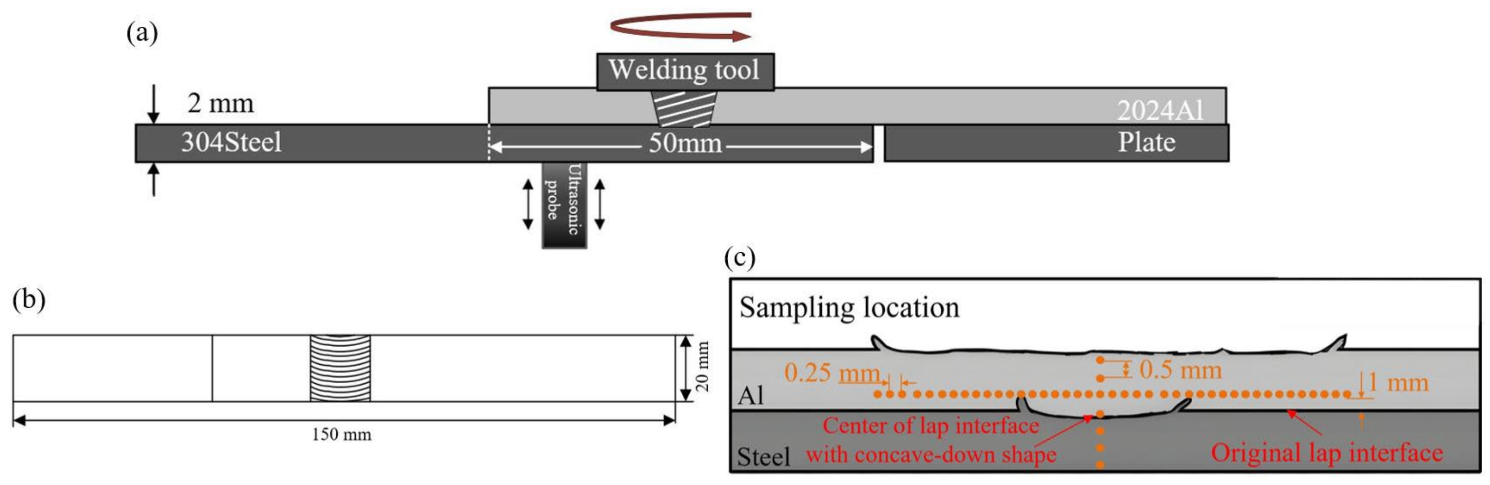
2. Materials and Methods

In the experiment, the upper and lower plates were 2024-T4 aluminum alloy and 304 stainless steel respectively, which were joined by the FSW-3LM-4012 friction stir welder (FSW, Fort Myers, FL, USA). As is known, for the butt joint by FSW, the steel plate is always put at the advancing side (AS) based on the difference in the thermal flow behaviors of these two materials [24,25,26]. For the lap joint, the aluminum alloy plate is often served as the upper plate in order to greatly decrease and even avoid the tool wear, and can be placed at the AS [30,33] or the retreating side (RS) [16,19]. In this study, the upper aluminum plate was placed at the AS, as displayed in Figure 1a. Before welding, the overlap area was cleaned with anhydrous ethanol to remove oil and impurities on the plate surface, and then the plates were fixed on a specially designed fixture. The size of the plate was 150 mm × 120 mm × 2 mm, the width of the overlap region was 50 mm. The separated ultrasonic vibration system was placed under the lower plate to be welded (Figure 1a). The ultrasonic power was chosen as 1500 W according to the ability of ultrasonic vibration system, and the distance between the ultrasonic probe and the weld center line was selected to be 20 mm according to previous works [12,34].
As is known, steel is a high-melting-point and high-strength metal, and WC-based alloys are often used to fabricate the welding tool and then friction stir butt weld similar steel materials [24] and dissimilar Al/steel materials [25,30] from the viewpoint of minimizing the tool wear. In fact, decreasing the contacting area between the tool and the base materials (BMs) to be welded is an effective method to reduce the tool wear, which is the main reason why the aluminum BM rather than the steel BM serves as the upper plate of lap joint and the tool pin slightly plunges into the lower plate during FSLW. In this study, the material of the welding tool with a conical pin was H13 steel [14,15,24]. In order to minimize the tool wear, the larger diameter of tool pin and the rational pin length were designed. For the tool used in this study, the diameter of the tool shoulder was 15 mm, the diameters of pin tip and diameter were, respectively, 5.5 mm and 4.5 mm, the length of the tool pin was 2 mm, and the plunge depth of tool shoulder into the upper plate was 0.05 mm. Thus, the plunge depth of the welding pin into the lower steel plate was 0.05 mm. It is known that sufficient material flow and the welding tool pin with a relatively small diameter are necessary for the FSW process in order to avoid volume defects such as cavities and tunnels [35,36]. Tufaro et al. [36] reported that the increased heat input could enhance the material flow during FSW. Considering that this study adopts a large tool pin diameter design, a large welding heat input under the high ratio of the rotating velocity to the welding speed is necessary. In this study, a constant welding speed of 75 mm/min was designed and the rotating velocities of 1000 rpm and 1200 rpm were chosen. Chitturi et al. [37] investigated the FSLW of 5052 aluminum alloy and 304 stainless steel at the tilt angles of 0°, 1.5°, and 2.5°, and found that the tilt angle of 2.5° eliminated weld defects including micro holes, cracks and even tunneling defects. Therefore, in this study, the 2.5° tilt angle of the welding tool was selected, and the welding tool rotated counterclockwise and moved along the centerline of the weld.
After welding, the experimentally achieved lap joints were subjected to metallographic observation and tensile shear tests, and the specimens were cut using a wire cutter with the cutting direction perpendicular to the welding direction. The width of the specimens for the tensile test was 20 mm, as displayed in Figure 1b. After polishing, the cross-section of the metallographic specimens was observed with the Olympus-GX51 optical microscope (LECO Corporation, St. Joseph, MI, USA), and the microhardness was determined by the HVS 1000 tester (LaiZhou Weiyi Experimental Machinery Manufacture Co., Ltd., Shandong, China) with a load of 20 N and a dwell time of 10 s. The microhardness was measured with the WILSON VH1102 hardness tester (Wilson, Houston, TX, USA) with a load of 200 g for 10 s, and two measured lines were chosen. One was located at the upper aluminum alloy and the distance between this line and the original lap interface was 0.5 mm; the other was distributed along the direction perpendicular to the original lap interface, as displayed in Figure 1c. The tensile shear test was carried out with the WDW-100 universal electronic material testing machine (HST) at room temperature with a loading speed of 2 mm/min. Each group of welding parameters was tested in three tensile shear specimens. Fracture characteristics and lap interface characteristics were analyzed using the CIQTEK-SEM3100 scanning electron microscope (Thermo Fisher Scientific Inc., Waltham, MA, USA) equipped with energy spectroscopy (EDS).

3. Results and Discussion

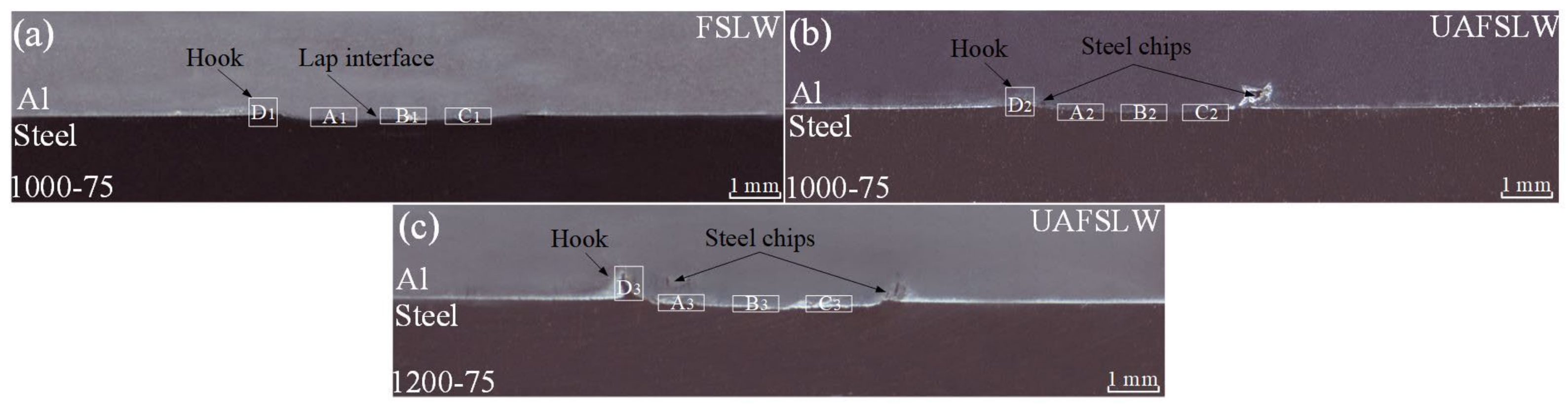
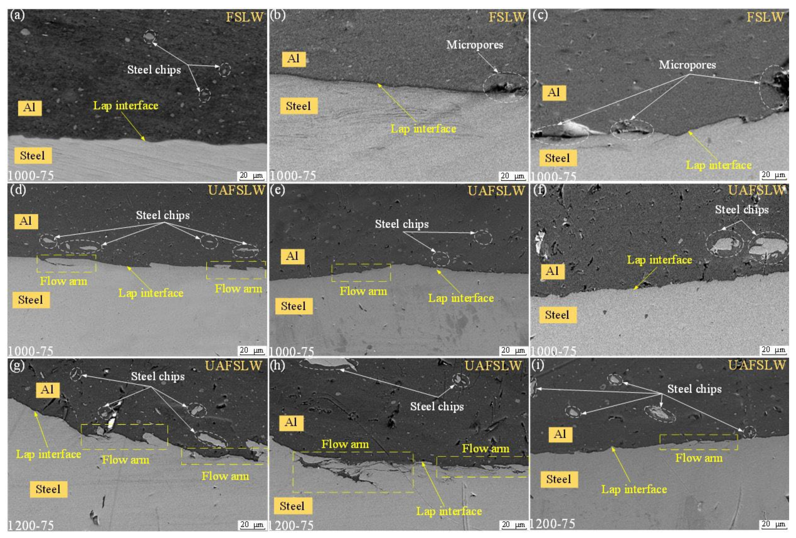
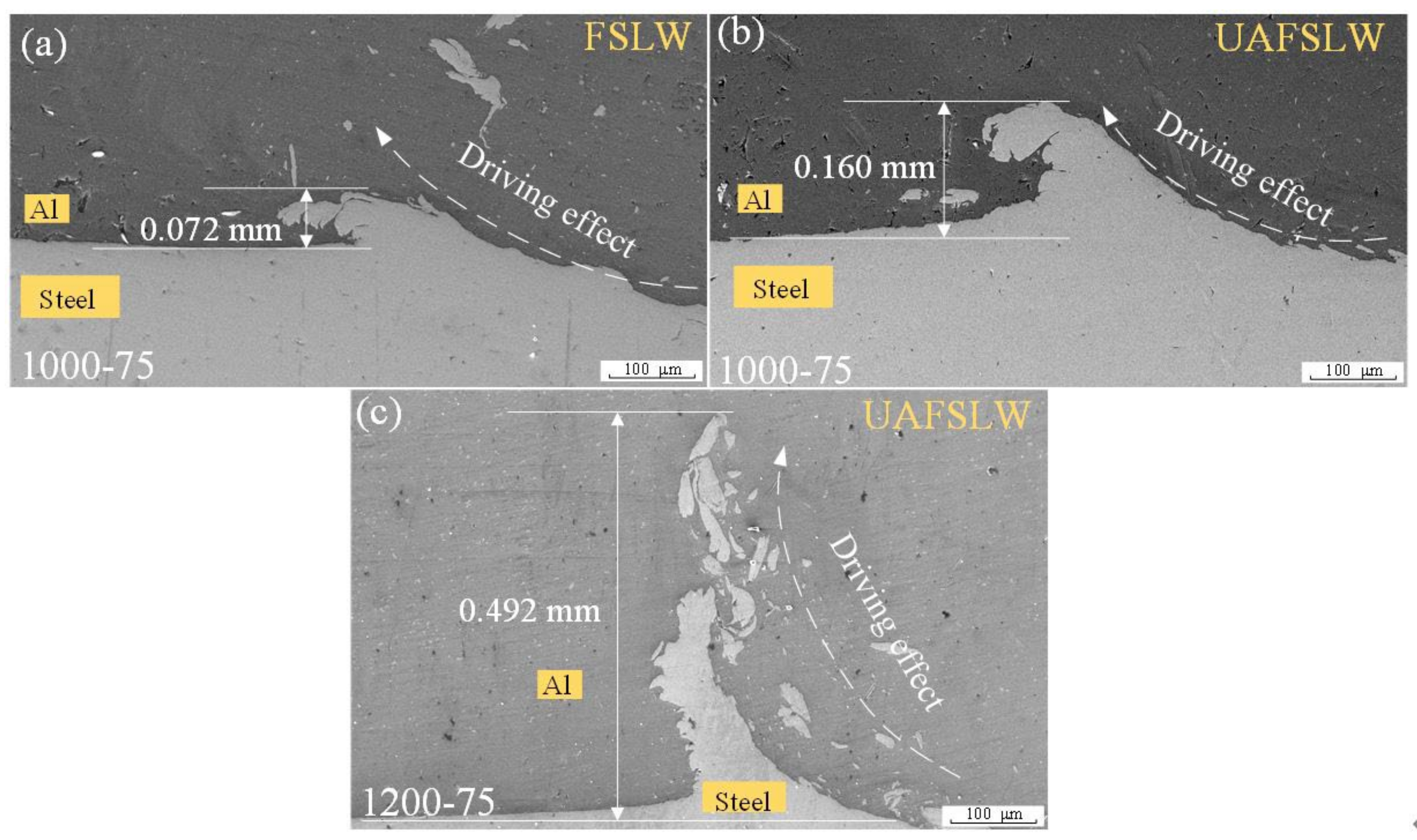
3.1. Joint Cross-Section

Figure 2 shows the cross-section morphologies of joints under different welding conditions. From the above-mentioned welding procedure, it is known that the tool pin plunges through the upper aluminum plate and then 0.05 mm into the lower steel plate. Ji et al. [10] reported that the region with high temperature during the FSW process was mainly located near the welding tool, and the temperature decreased with increasing the distance away from the welding tool. Because the melting point of steel is higher than that of aluminum alloy, the region with high temperature during welding is mainly located at the lap interface between the upper aluminum and lower steel plates [18,38]. Combined with the steel BM having a strength much higher than the aluminum BM, the plunging movement of the tool pin makes the materials in the lower plate contacting the tool pin flow upwards and then into the upper aluminum alloy due to the minimum resistance law [39,40], thereby leading to the concave-down shape and hook structure at the lap interface (Figure 2). Similar morphology features of the lap interface are also reported by some researchers such as Ji et al. [10], Chen et al. [18], Liu et al. [30], and so on. In order to more thoroughly analyze the formation features at the lap interface, typical regions are enlarged and displayed in Figure 3 and Figure 4.
Figure 3 displays the enlarged photos of typical regions with a concave-down shape under different welding conditions. During welding, the welding tool with high rotating velocity contacts with the top surface of the lower steel plate, and peels some materials off the steel plate and then breaks them into small chips. These small steel chips are driven into the upper aluminum plate, as displayed in Figure 3. Ji et al. [10], Liu et al. [30], and Chitturi et al. [37] also found the steel chips in the upper aluminum plate when the upper aluminum and the lower steel were welded using the FSLW process. Zhong et al. [41] reported that the addition of ultrasound during welding did not result in any obvious elevation of temperature. As is known, the steel is more easily stripped off the steel plate under the higher temperature of steel BM. Thus, compared with the traditional FSLW process (Figure 3a–c), the UAFSLW process makes more and larger steel chips into the upper aluminum plate (Figure 3d–i), which is only attributed to the enhanced flow behavior and mechanical vibration effect by the ultrasound [42,43]. Due to many steel chips that are peeled off the top surface of the steel plate under the action of the welding tool, the regions with micromechanical interlocking were found at the lap interface (Figure 3a,c). Compared with the traditional FSLW joint, the UAFSLW joint has more and better micro-mechanical interlocking regions with deeper pits at the lap interface (Figure 3d–i). According to the reported results by Kumar et al. [43], the ultrasonic vibration enhances the material flow behavior, causing the materials to fill up volume defects such as cavities or gaps formed during welding, thereby eliminating the volume defects in the welded FSW joint. This similar phenomenon occurs in this study, and the micropores are observed in the lap interface under the traditional FSLW process (Figure 3b,c) rather than the UAFSLW process. Moreover, the flow arm structure, which means some aluminum materials are moved into the lower steel plate, is found in the UAFSLW joint (Figure 3d,g,h) rather than the traditional FSLW joint, which results from the enhanced material flow by ultrasound. Liu et al. [30] performed the FSLW process of dissimilar aluminum alloy and steel materials, and observed the flow arm structure in the welded lap joint.
Figure 3. Typical enlarged views of lap interfaces with concave-down shape: regions A1 (a), B1 (b) and C1 (c) marked in Figure 2a; regions A2 (d), B2 (e) and C2 (f) marked in Figure 2b; regions A3 (g), B3 (h) and C3 (i) marked in Figure 2c.
Metals 14 00267 g003
Figure 4 presents the enlarged views of regions with hook structure under different welding conditions. As mentioned above, the steel materials flow into the upper aluminum alloy plate and then form the hook structure. The formation process of hook structure by the tool pin is similar to that of flash on the top surface of welded joint, which results from the materials flowing out of the plate due to the welding tool plunging into the plate [44]. The size of the hook structure is closely related to the material flow ability. Kumar et al. [43] reported that the addition of ultrasound during FSW enhanced the material flow ability. Therefore, the height of the hook in the UAFSLW joint (Figure 4b) is larger than that in the traditional FSLW joint (Figure 4a) due to the enhancement. Under the same process parameters including the 1000 rpm rotating velocity, the 70 mm/min welding speed, and the 0.05 mm plunging depth, the addition of ultrasound makes the height of the hook increase to 0.160 mm from 0.072 mm.
Figure 4. Typical enlarged views of typical regions with hook structure: (a) region D1 marked in Figure 2a, (b) region D2 marked in Figure 2b, and (c) region D3 marked in Figure 2c.
Metals 14 00267 g004
According to the reported results by Kimapong and Watanabe [20] and Geng et al. [44], increasing the rotating velocity of welding tool not only elevates the temperature but also enhances the flow velocity of material during FSW. Geng et al. [44] reported that the increased temperature decreases the deformation resistance of the material and then enhances the flow ability of the material. Moreover, the decreased deformation resistance of the material is beneficial to heightening the ability of the welding tool to peel the steel chips off the steel plate. Therefore, compared with the UAFSLW joint at 1000 rpm (Figure 3d–f and Figure 4b), the UAFSLW joint at 1200 rpm has a larger and higher hook structure, a better micro-mechanical interlocking structure with more and deeper pits at the lap interface, and more flow arms in the lower steel plate. When the rotating velocity of the welding tool increases from 1000 rpm to 1200 rpm, the hook height of the UAFSLW joint increases to 0.492 mm (Figure 4c) from 0.160 mm (Figure 4b). In fact, the hook structure can serve as the macro-mechanical interlocking structure, and it together with the micro-mechanical interlocking on the concave-down shape part at the lap interface play a positive role in improving the joint loading capacity [5,30].

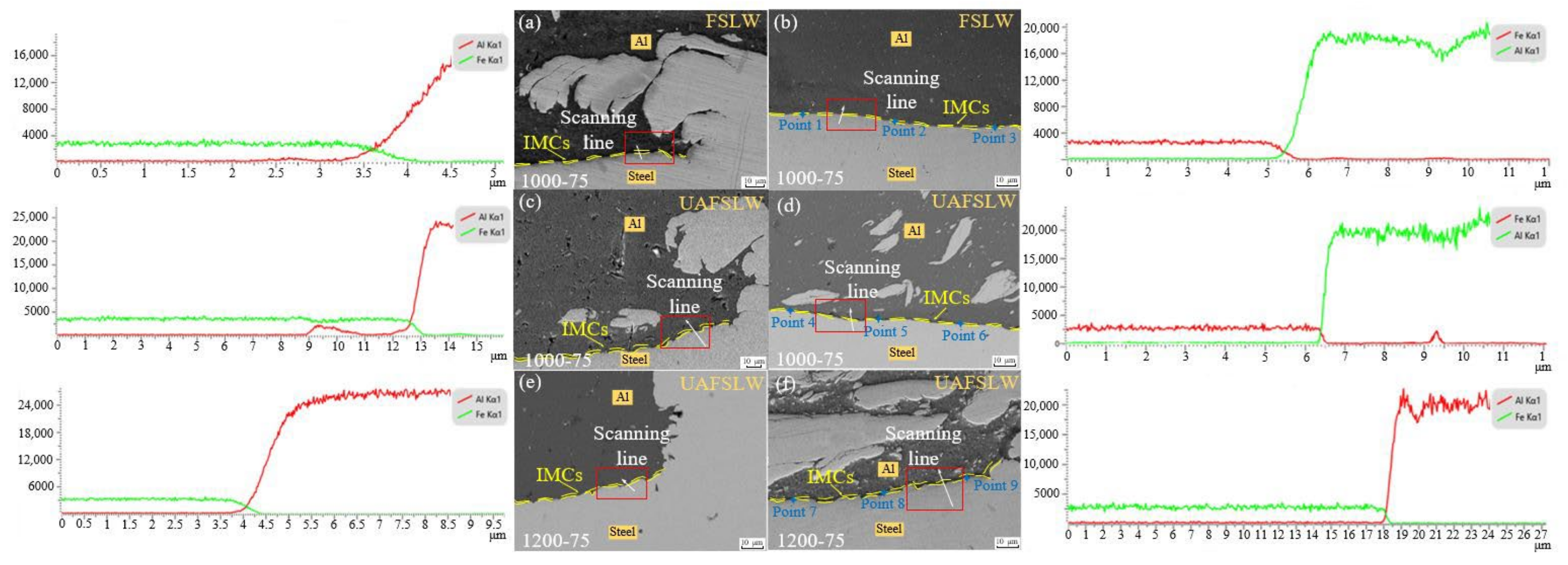
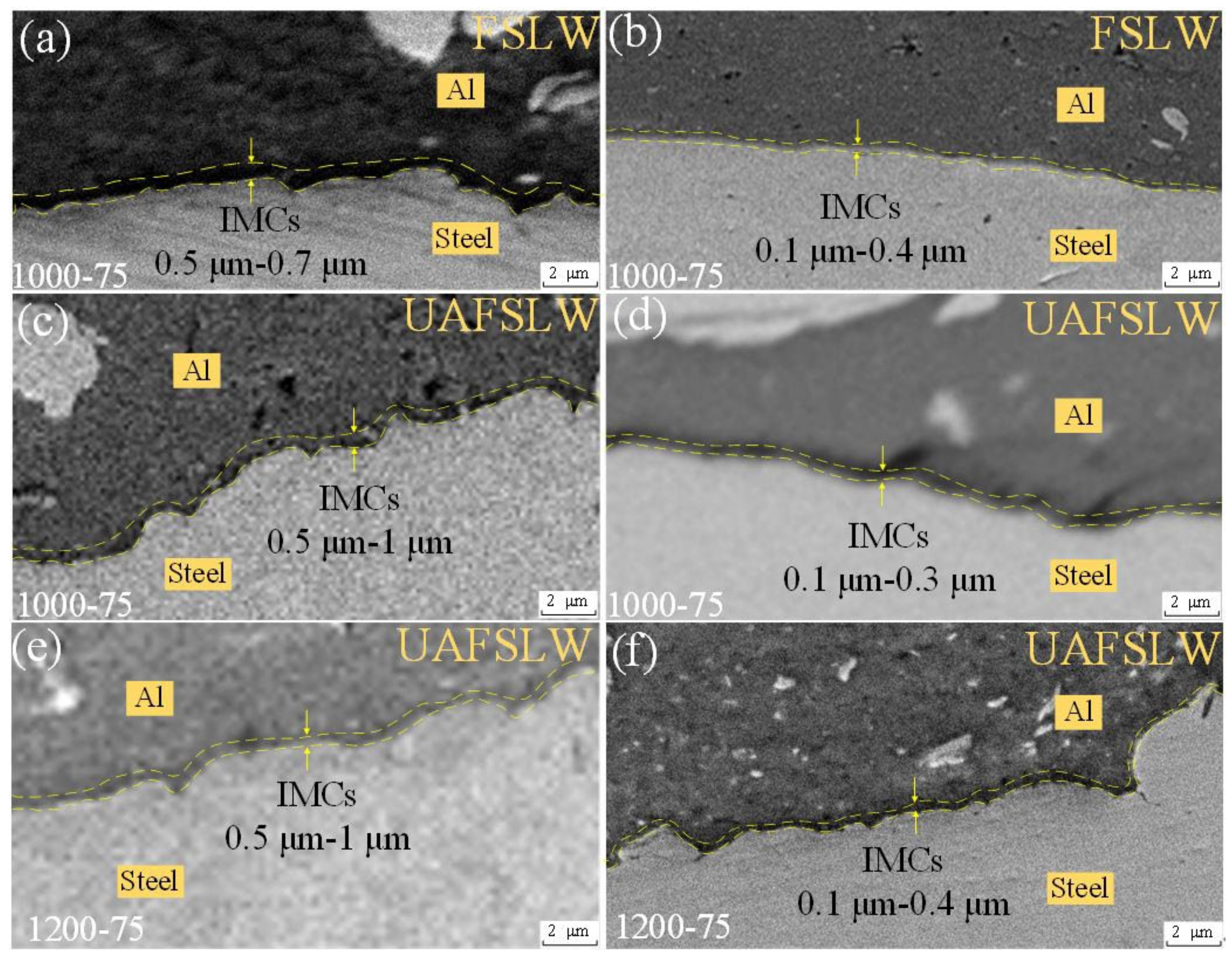
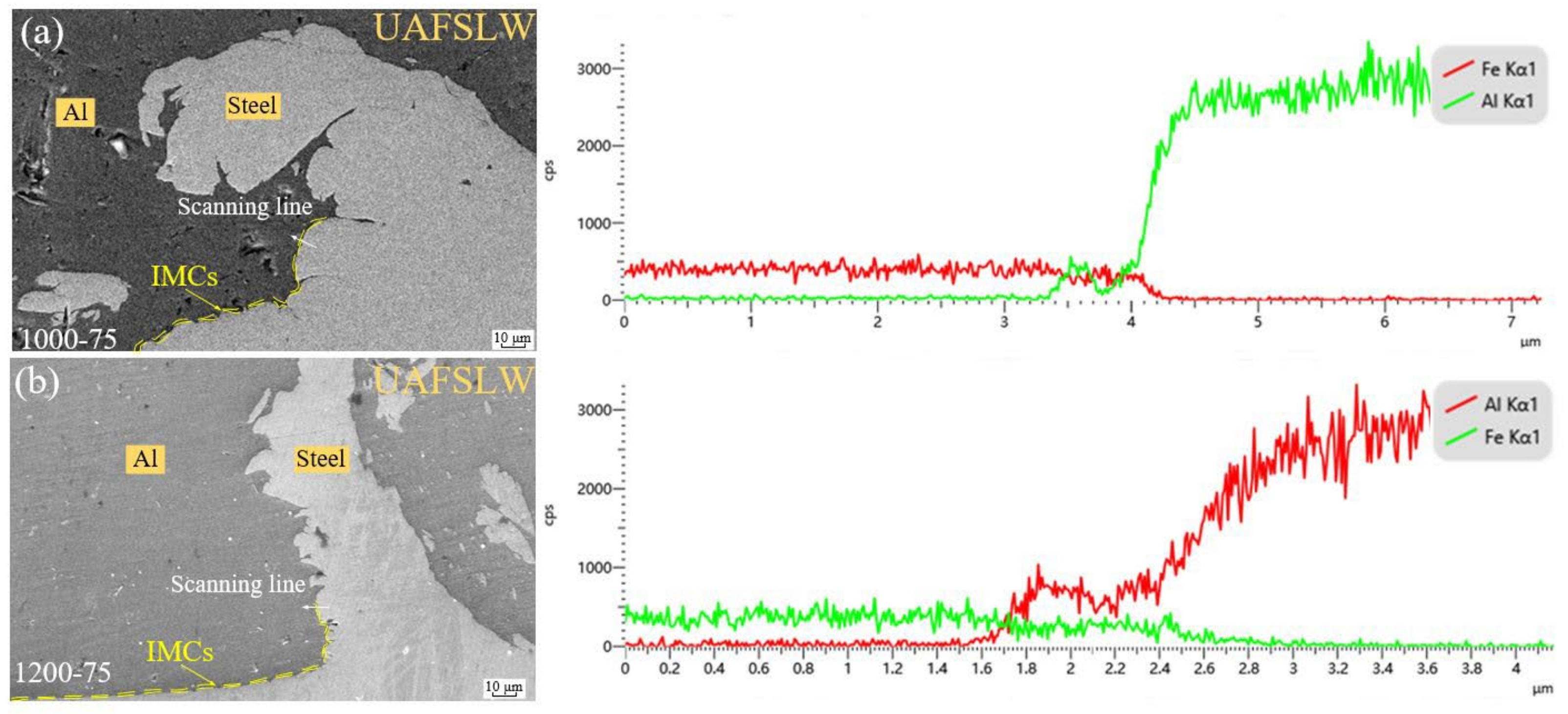
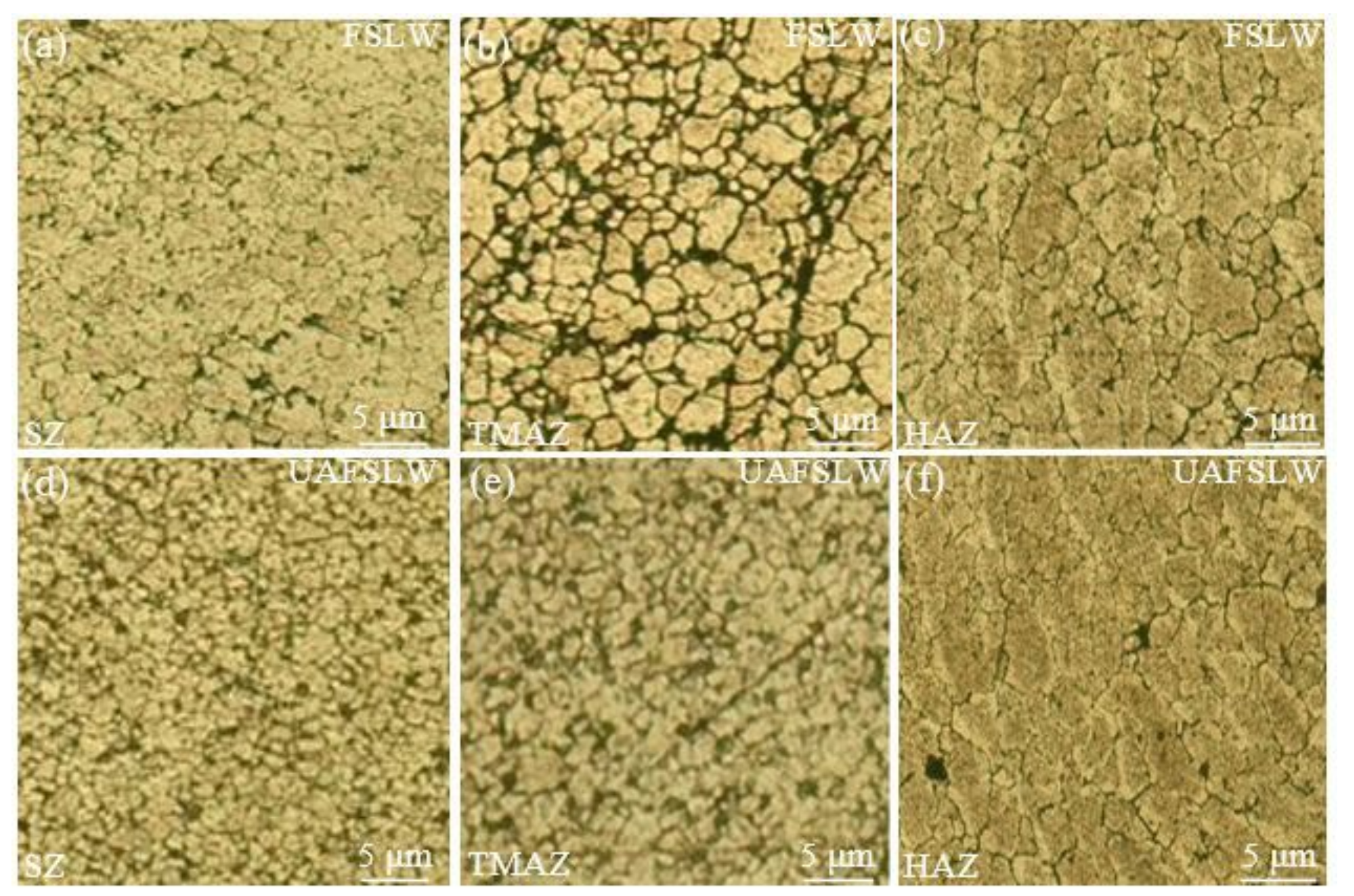
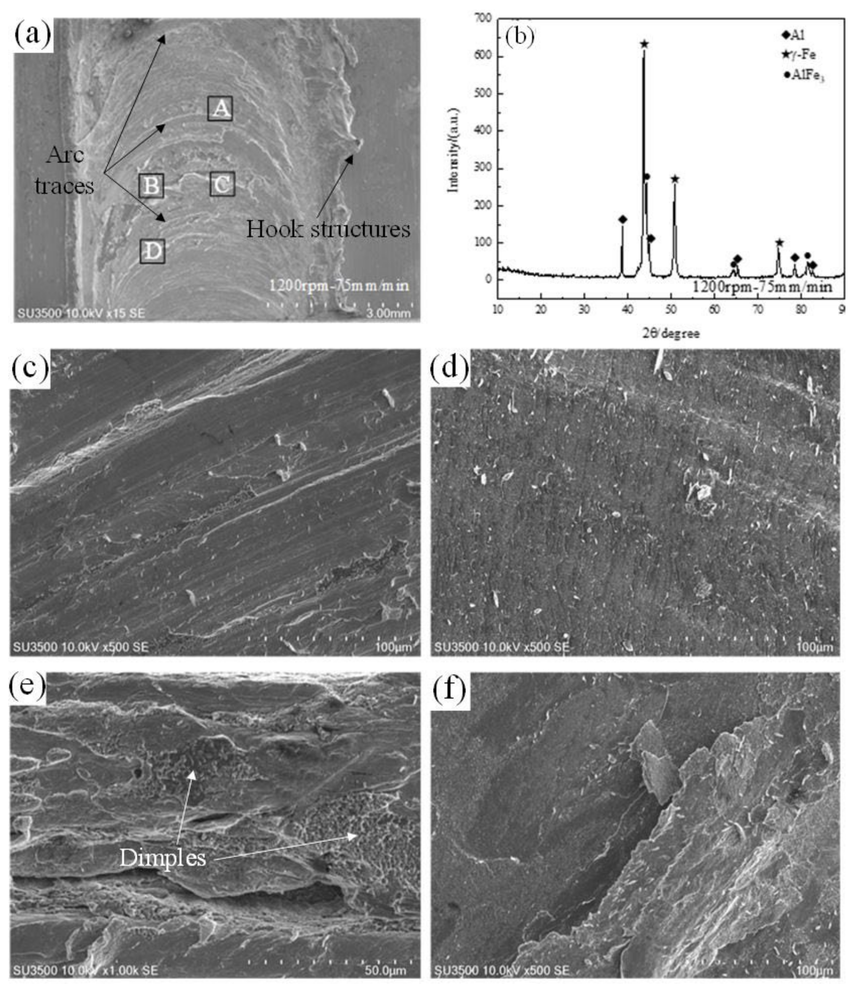
3.2. Atom Diffusion and Grain Size

Similar to other FSLW joints of dissimilar metals [4,10,45], the Al/steel FSLW joints are welded based on metallurgical bonding. The atom interdiffusion between the aluminum alloy and the steel is a prerequisite for metallurgical bonding, so the atom interdiffusion near the typical Al/steel interface regions was observed using the EDS method and the results are displayed in Figure 5. Similar to the reported literature [16,18,33], this study analyzes the atom diffusion of main elements including Al and Fe. Thereinto, the regions D1, D2, and D3 scanned by the EDS method are located outside the stir zone (SZ) and the distances between the scan line and the hook structure are nearly the same, while the regions B1, B2, and B3 scanned by the EDS method are located in the middle of concave-down lap interface in the SZ. Liu et al. [30] reported that the ultrasonic could enhance the velocity of atom interdiffusion during the FSW. In this study, under the same rotating velocity of 1000 rpm, the distances of atom interdiffusion along the scan line outside the SZ are respectively about 0.85 μm under traditional FSLW (Figure 5a) and 1.2 μm under UAFSLW (Figure 5c), and the heightened distance of atom interdiffusion of UAFSLW joint results from the effect of ultrasonic. However, the phenomenon of the enlarged distance of atom interdiffusion outside the SZ under the ultrasound does not occur in the SZ. From Figure 5b,d, it is known that the 0.6 μm distance of atom interdiffusion in the SZ under the traditional FSLW process is larger than the 0.3 μm value under the UAFSLW process. During FSLW, the ultrasound enhances not only the atom diffusion but also the material flow, and the enhanced material flow perhaps peels part of lap interface off the lap interface to form the chips in the SZ (Figure 3). This phenomenon of these peeled-off steel chips means that the addition of ultrasound during FSLW decreases the distance of atom diffusion.
During welding, the peak temperature is located near the welding tool and increases with increasing the rotating velocity of welding tool [9,46]. According to the discussions reported by Kimapong and Watanabe [20], it is known that the increased temperature is beneficial to heightening the velocity of atom interdiffusion and then increases the distance of atom interdiffusion. When the ultrasound is used, the region in the SZ at 1200 rpm owns the 0.6 μm distance of atom interdiffusion (Figure 5f) larger than the 0.3 μm distance at 1000 rpm (Figure 5d), which is mainly attributed to the increased temperature [46]. However, for the regions outside the SZ of the UAFSLW joint, the distance of atom interdiffusion at 1200 rpm (Figure 5e) is smaller rather than larger than that at 1000 rpm (Figure 5c) even if the welding temperature at 1200 rpm is higher than that at 1000 rpm [9], which is related to the difference in hook morphologies. The region outside the SZ is not directly heated by the welding tool and its temperature elevation during welding is related to the heat conduction from the materials with higher temperature. During FSLW, the hook structure extending into the upper aluminum plate owns higher temperature and heated its nearby region. The hook structure in Figure 5c shows the down-bending morphology at the tip and in Figure 5e it is upward. Under this condition, the location of the scan line in Figure 5c perhaps experiences more heat from the hook structure due to the increased size of the region heating the scan line location, which means that the distance of atom interdiffusion at 1000 rpm (Figure 5c) is bigger than that at 1200 rpm (Figure 5e). According to the reported literature [5,30], it is known that the thickness of the IMC layer is smaller than the distance of atom interdiffusion. The thickness values of the IMC layer on the typical regions were measured (Figure 5), and the enlarged view is further given in Figure 6.
Figure 5. Enlarged views of typical regions and their EDS results by line scan: (a,b) regions D1 and B1 marked in Figure 2a; (c,d) regions D2 and B2 marked in Figure 2b; (e,f) regions D3 and B3 marked in Figure 2c.
Metals 14 00267 g005
Figure 6. Enlarged views of typical regions: (af) region in red rectangular frame marked in Figure 5a–f.
Metals 14 00267 g006
Figure 7 shows the EDS analyses of typical locations on the hook structures of UAFSLW joints. These two locations in Figure 7 are both located at the outer wall of the hook structure, so the atom interdiffusion is mainly related to the temperature rather than the material flow. Based on the discussions mentioned above, it is known that the hook structure extending into the upper aluminum plates has a relatively high temperature and this temperature is closely related to the peak temperature near the Al/steel lap interface. The UAFSLW joint at 1200 rpm has a peak temperature higher than the joint at 1000 rpm [9], so it is considered that the temperature on the location for the scan line of EDS analysis at 1200 rpm is higher than that at 1000 rpm. Therefore, the 0.8 μm distance of atom interdiffusion at 1000 rpm (Figure 7a) is smaller than the 1.4 μm value at 1200 rpm (Figure 7b). According to the simulation results by Geng et al. [44], it is known that the temperature outside the SZ decreases with the distance away from the welding tool. For the UAFSLW joint at 1200 rpm, the 1.4 μm distance of atom interdiffusion at the outer wall of the hook (Figure 7b) is larger than the 0.6 μm value at the lap interface outside the SZ (Figure 5e) due to the difference in temperature. Combined with the results in Figure 5c–f and Figure 7, it is known that the elevated temperature is beneficial to enhancing the atom diffusion velocity at the Al/steel interface, and the temperature of materials outside the SZ is influenced by several factors including the welding process combination, the distance away from the SZ and the size of nearby region with high temperature.
It is well known that the IMCs are the products of the atom interdiffusion, and its thickness is smaller than the distance of atom interdiffusion [29,30]. Geng et al. [44] reported that an IMC layer thickness lower than 1.5 μm at the Al/steel interface was beneficial to heightening the strength of lap joint. According the discussions reported by Dong et al. [33] and Liu et al. [30], the IMC layer thickness lower than 2 μm is positive on the loading capacity of dissimilar aluminum and steel alloys FSLW joint. In this study, the IMC thickness is necessarily smaller than 1.5 μm (Figure 5, Figure 6 and Figure 7) since the largest distance of atom interdiffusion in Figure 5 and Figure 7 is only 1.4 μm, which is the suitable value from the viewpoint for heightening the FSLW joint strength. In fact, besides the IMC layer thickness, the IMC type influences the loading capacity of the Al/steel FSLW joint. Therefore, the typical nine points marked in Figure 5b,d,f were analyzed using EDS, and the results are shown in Table 1. Based on the results in Table 1 and the location position in Figure 5, it is known that the concave-down lap interface in the traditional FSLW joint mainly has two aluminum-rich IMC types including Al5Fe2 and Al13Fe4, and the lap interface in the UAFSLW joint has iron-rich IMC types including AlFe and AlFe3. Azizieh et al. [47] reported that aluminum-rich IMC types such as Al6Fe, Al4Fe, Al3Fe, and Al2Fe had relatively high brittleness and the iron-rich IMC types such as AlFe and AlFe3 had relatively high toughness. It is known that compared with the high brittleness of IMCs, the high toughness of IMCs is beneficial to enhancing the bonding strength at the Al/steel interface. Therefore, based on the difference in IMC type, it is inferred that the addition of ultrasound during FSLW is beneficial to heightening the loading capacity of the welded lap joint.
In this study, the microstructures of upper aluminum alloy in the welded joint at 1000 rpm were observed, as displayed in Figure 8. Due to the dynamic recrystallization under the high temperature and strong material flow [30,48], the SZ consists of fine equiaxed grains. As mentioned above, the addition of ultrasound results in no obvious change of temperature during welding [41]. Thus, the grain size in SZ is mainly related to material flow behavior during FSLW. Amini et al. [49] reported that the addition of ultrasound enhanced the material flow during FSW. Liu et al. [30] reported that the grain size in the SZ was refined due to the enhanced the material flow during FSW assisted by ultrasound. A similar phenomenon is obtained in this study. The grain size in the SZ of the traditional FSLW joint (Figure 8a) is smaller than that of the UAFSLW joint (Figure 8d). Compared with the traditional FSLW joint (Figure 8b), the UAFSLW joint has a thermo-mechanically affected zone (TMAZ) with finer grains (Figure 8e) due to the enhanced plastic flow state under the ultrasound [30]. However, the addition of ultrasound does not result in an obvious change in grain size in the heat-affected zone (HAZ) (Figure 8c,f), which is attributed to the temperature during UAFSLW being nearly the same as that during traditional FSLW [41]. According to the results reported by Vysotskiy et al. [50] and Guo et al. [51], the refined grains in the joints are beneficial to heightening the joint loading capacity so long as the crack during tensile testing propagates along the joint thickness, whether it is a butt joint or a lap joint fabricated by the FSW process. However, the effect of the refined grains on the loading capacity of the Al/steel FSLW joint can be omitted in this study, because the shear fracture rather than the tensile fracture is obtained.

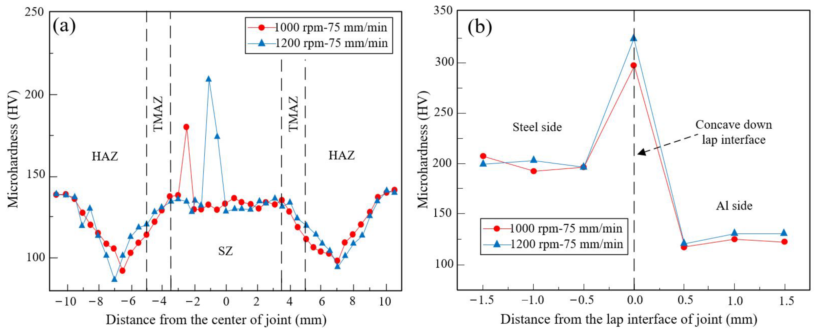
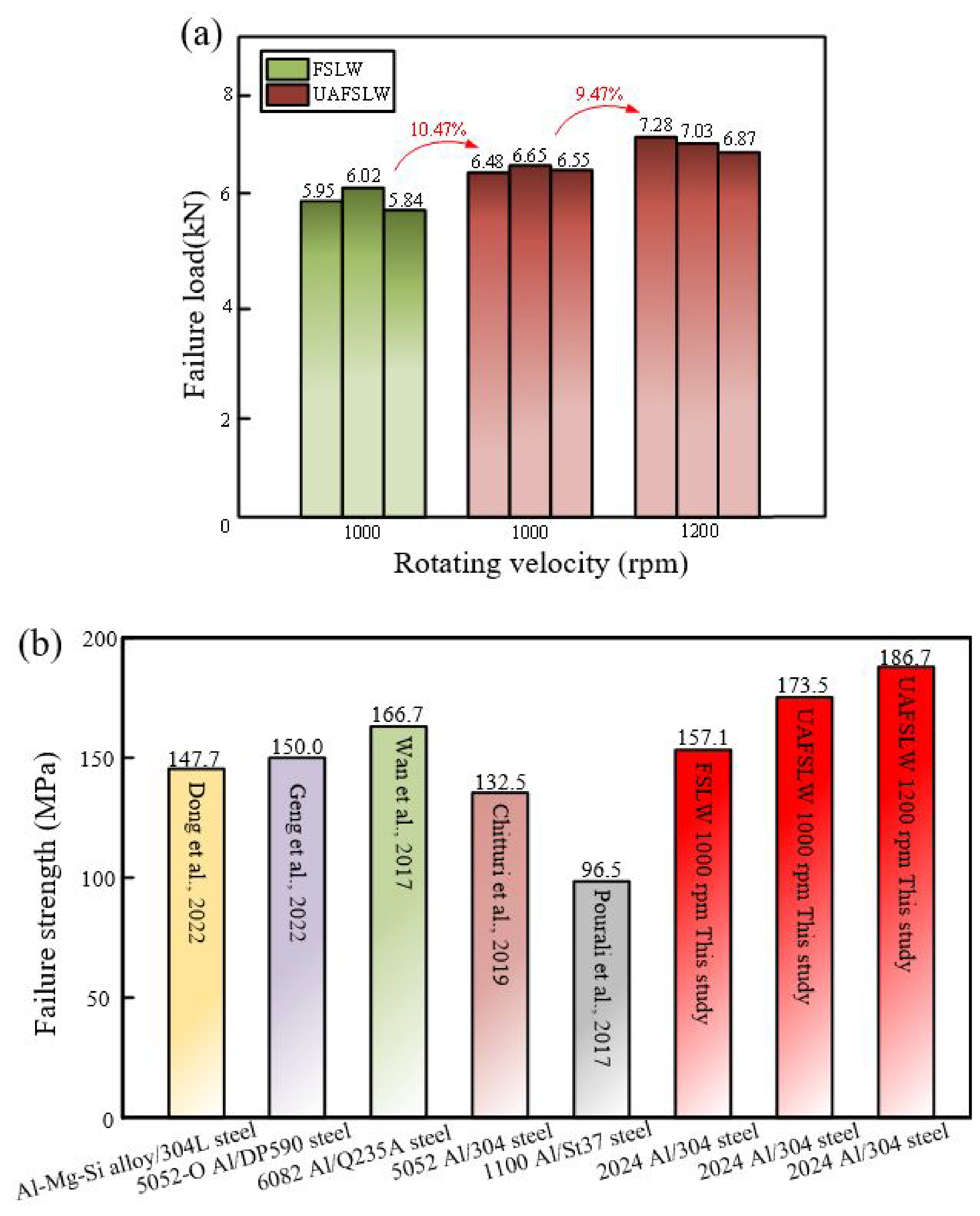
3.3. Mechanical Properties

Figure 9 displays the microhardness distributions of joints using UAFSLW, and the measured points are shown in Figure 1c. As is well known, the FSW joint can be divided into SZ, TMAZ, HAZ, and BM [5,9,30]. 2024-T4 aluminum alloy is a kind of aluminum alloy strengthened by heat treatment, and its microhardness values in the SZ, TMAZ, and HAZ of the FSW joint are lower than the microhardness value in the BM, which is mainly attributed to the coarsening of the strengthening particles in the HAZ and the dissolution of strengthening particles in the SZ and TMAZ [15,30,52]. The microhardness distribution along the direction parallel to the original lap interface is similar to the above-mentioned distribution reported by Liu et al. [15] and Liu et al. [30]. However, there are some points with a microhardness higher than the 145 Hv microhardness of 2024 aluminum alloy BM, which results from the steel chips into the upper aluminum plate, and the 304 steel BM with a microhardness 220 Hv higher than 2024 aluminum alloy BM. Ji et al. [53] performed the FSLW of 2024 aluminum alloys and stated that the softening region was widened and the minimum microhardness value outside the SZ was decreased under the higher heat input. A similar phenomenon is obtained in this study (Figure 9a). For the UAFSLW joint, the minimum microhardness of the joint at 1200 rpm is 37.5 Hv, and this value is 22.7 Hv smaller than the 60.2 Hv value at 1000 rpm. Moreover, the number of high-microhardness points and the corresponding microhardness values in the SZ at 1200 rpm are both larger than those in the SZ at 1000 rpm, which can be attributed to more and larger steel chips into the upper aluminum alloy plate at 1200 rpm (Figure 3).
In Figure 9b, the highest microhardness value is located at the lower point of the concave-down lap interface, while the microhardness values of points in the lower plate are higher than those in the upper plate because the steel BM has higher microhardness than the aluminum BM. According to the measured values reported by Wan et al. [9], Liu et al. [15], and Liu et al. [30], it is known that the Al-Fe IMCs have higher microhardness than steel BM. The Al-Fe IMCs appear near the lower point of the concave-down lap interface (Figure 5 and Table 1), so this point obtains the highest microhardness value (Figure 9b). Based on the results in Figure 6 and the above-mentioned discussion, it is inferred that due to the enlarged IMC layer thickness, the microhardness value at the lower point of the concave-down lap interface of the joint at 1200 rpm is higher than that at 1000 rpm. Wan et al. [9] performed the FSW of 6082-T6 aluminum and Q235A steel metals and reported that the Al-Fe IMC microhardness value was 349 Hv. In this study, the highest microhardness value of 323 Hv obtained at 1200 rpm is smaller than the 349 Hv reported by Wan et al. [9], which can be attributed to the relatively small thickness of Al-Fe IMCs.
Figure 9. Microhardness distributions of UAFSLW joints along the direction (a) parallel to and (b) perpendicular to the original lap interface.
Metals 14 00267 g009
In this study, the failure loads of FSLW joints under different welding conditions were tested, and the results are presented in Figure 10a. In order to better explain the advantages of ultrasound addition during the FSLW process of aluminum to steel, the failure strengths of FSLW joints in this study and the reported literature [9,16,33,37,44] are compared, as displayed in Figure 10b. Therein, the failure strength in Figure 10b means the failure strength is obtained by dividing the maximum failure load by the width of test specimen and the thickness of the upper plate. In this study, the traditional FSLW joint has a failure load of 5.94 kN, and the addition of ultrasound heightens the failure load of the welded lap joint. When the rotating velocity increases from 1000 rpm to 1200 rpm, the failure load of the UAFSLW joint reaches the maximum value of 7.06 kN from 6.56 kN (Figure 10a). Dong et al. [6] performed the traditional FSLW of aluminum to steel and the upper aluminum alloy plate had a thickness of 2 mm. Their results show that the maximum failure load of 4.43 kN is obtained, and this value is much smaller than the 5.94 kN failure load of traditional FSLW joints in this study. This phenomenon results from the welding tool not plunging into the lower steel plate and no mechanical interlocking formed at the Al/steel lap interface in Ref. [33]. Combined with the results in Refs. [9,16,33,37,44] and the results in this study, it is known that for the traditional FSLW joint, the 157 MPa failure strength in this study is a relatively high value, which is attributed to the formation of macro-mechanical interlocking (Figure 4a) and a rational IMC layer smaller than 1.5 μm (Figure 5, Figure 6 and Figure 7). It is noteworthy that in the reported literature [16], the minimum failure strength of dissimilar aluminum and steel metal FSLW joints is only 96.5 MPa. The reason why the reported strength of joint in Ref. [16] is very low is that the BM of the upper plate is the low-strength pure aluminum and the fracture mode is the tensile fracture. In fact, when the BMs of upper plate are 2024 [15] and 5052 [44] series aluminum alloys, the main fracture mode is the shear fracture mode because the BM of the upper plate has a relatively high strength. In this study, only the shear fracture mode of the welded lap joint is obtained, and the corresponding schematic diagrams under the traditional FSLW and UAFSLW processes are drawn (Figure 11).
When the FSLW joint bears the external tensile shear load, there are two fracture modes including the tensile fracture [54] and the shear fracture [29]. For the FSLW joint of aluminum to steel, the fracture mode is always the shear fracture mode because the formation of brittle Al-Fe IMCs at the Al/steel lap interface always becomes the crack source and the crack propagation path [30], and the shear fractured lap joint in this study is displayed in Figure 11a. Under the shear fracture mode, the crack mainly propagates along the lap interface after welding rather than along the direction perpendicular to the lap interface [55], so the morphologies along the lap interface rather than the microstructures in the SZ, and the steel chip in the upper aluminum plate determines the loading capacity of the FSLW joint. In Figure 11a, some traces of the hook and pit structures can be seen on the lower surface of the upper aluminum plate, which is caused by these structures left in the upper surface of the lower steel plate. Figure 11b,c are, respectively, the schematics of shear fractured joints by traditional FSLW and UAFSLW, which are drawn according to the interface features of the joint and used to explain how the micro- and macro-mechanical interlocking effects influence the joint failure strength. For the FSLW joint, the failure load is mainly determined by the fracture location and the length and complexity of the fracture path [30,56]. Nian et al. [57] reported that the micro- and macro-mechanical interlockings in dissimilar materials’ FSLW joints enhanced the joint loading capacity due to the lengthened fracture path and the enhanced path complexity. In this study, the traditional FSLW joint rather than the UAFSLW joint has micropores (Figure 3b,c), and the pores decrease the length of the fracture path under the shear fracture mode and go against the loading capacity of the welded lap joint. Compared with the traditional FSLW (Figure 3a–c and Figure 11a), the UAFSLW joint (Figure 3d–i) has a larger size and larger depth of micro-mechanical interlocking, thereby having a higher failure strength. From Figure 4 and Figure 11, it is known that the macro-mechanical interlocking effect of the hook structure with a larger size in the UAFSLW joint is better than that in traditional FSLW, which is another factor in heightening the failure strength due to the addition of ultrasound. Therefore, under the reasonable IMC thickness lower than 1.5 μm in all the joints of this study [44], these above-mentioned three positive factors together with the formation of the iron-rich IMCs along the lap interface means that the addition of ultrasound enhances the failure strength of the welded lap joint and the maximum failure strength of 186.7 MPa is higher than the strength values of reported literature (Figure 10b). Moreover, for the UAFSLW joint, not only the micro-mechanical interlocking but also the macro-mechanical interlocking of the joint at 1200 rpm (Figure 3g–i and Figure 4c) are better than those at 1000 rpm (Figure 3d–f and Figure 4b), so the failure strength at 1200 rpm is larger than that at 1000 rpm (Figure 10b).
Figure 11. (a) Fractured lap joint after tensile test; schematics of shear fractured joints by (b) traditional FSLW and (c) UAFSLW.
Metals 14 00267 g011
In this study, the characteristics of the fracture surface of the Al/steel UAFSLW joint were analyzed, and the research object was chosen as the steel side of fractured joint. Figure 12a displays the fracture surface and some arc traces are found. The formation of arc traces is thought to be caused by the pin tip slightly plunging into the lower steel, and this formation is similar to the formation of marks on the joint top surface by the tool shoulder [58]. Moreover, because the hook structure is composed of high-strength steel, it is not separated from the lower steel plate under the external tensile load as observed in Figure 12a. Figure 12b shows the result by XRD and the iron-rich AlFe3 IMC is found, which verifies the analysis about IMC types of typical points at the lap interface in Table 1. Figure 12c–f displays the enlarged views of typical regions on the fracture surface in Figure 12a, and the cleavage steps and dimples (Figure 12e) are both observed. Thus, the UAFSLW joint presents the brittle–ductile mixed fracture and this similar fracture is also reported by Liu et al. [15] and Chittuiri et al. [37].

4. Conclusions

Under the addition of ultrasound during FSLW and the welding tool slightly plunging into the lower steel plate, dissimilar 2024-T4 aluminum alloy and 304 stainless steel metals were successfully joined. The interface characteristics and mechanical properties under different welding conditions were compared. The following conclusions were obtained.
(1)
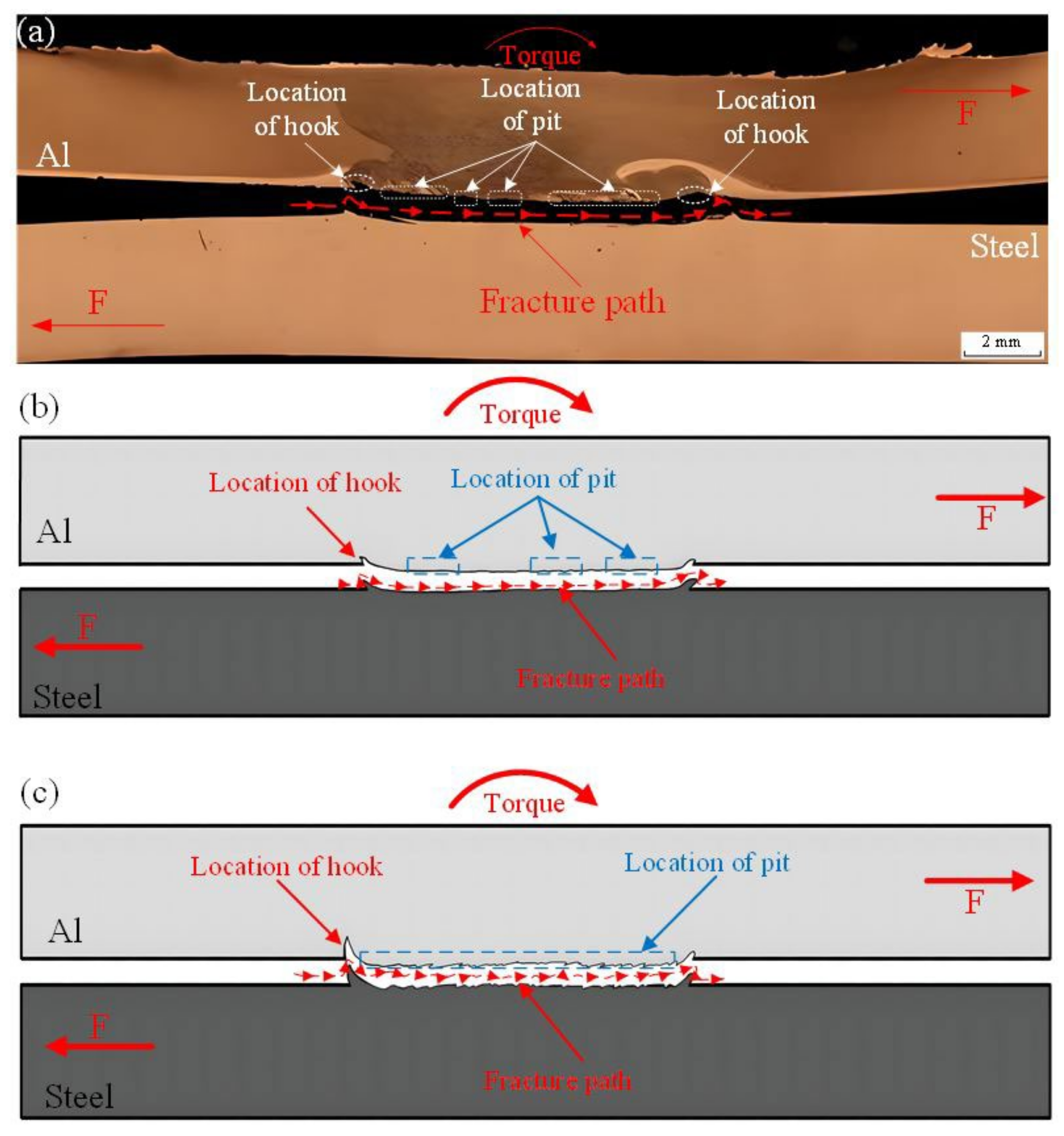
Under the positive effect of ultrasound, the joint was fabricated with the improved interface features including no micropores, more and larger pits, and larger hook structure. The pit and the hook structure at the lap interface played a role of the micro- and macro-mechanical interlocking structures, respectively. The addition of ultrasound not only made more and larger steel chips into the upper aluminum plate but also determined the amount of aluminum materials in the lower steel plate and formed the flow arm structure.
(2)
The addition of ultrasound increased the atom interdiffusion distance near the Al/steel interface outside the SZ, and decreased the atom interdiffusion distance in the SZ. Whether the traditional FSLW or the UAFSLW was used, the thickness of the IMC layer was controlled within 1.5 μm which was positive on the loading capacity of the lap joint.
(3)
The UAFSLW joint had a failure strength higher than the traditional FSLW joint, and the strength of the UAFSLW joint at 1200 rpm was larger than that at 1000 rpm. The maximum strength value of the UAFSLW joint reached 186.7 MPa, which was much larger than that of the reported joint of aluminum to steel. The welded joint shear fractured along the lap interface and presented a brittle–ductile mixed fracture.

Author Contributions

Conceptualization, L.H., D.Y. and L.M.; literature search, Z.Y.; data collection, Z.Y. and Y.R.; figures, L.M. and Z.Y.; formal analysis L.H., Z.Y., D.Y. and Y.R.; methodology, L.H. and Z.Y.; writing—original draft preparation, L.H. and Z.Y.; writing—review and editing: L.M. All authors have read and agreed to the published version of the manuscript.

Funding

This project was supported by the Natural Science Foundation project of Liaoning Province (2023-MS-238) and the Guangdong Special Branch Plans (2023TX07H218).

Data Availability Statement

The raw data supporting the conclusions of this article will be made available by the authors on request.

Conflicts of Interest

Authors Dejun Yan and Yuzhong Rao were employed by the company CSSC Huangpu Wenchong Shipbuilding Company Limited. The remaining authors declare that the re-search was conducted in the absence of any commercial or financial relationships that could be construed as a potential conflict of interest.

References

  1. Hussein, S.A.; Tahir, A.S.M.; Hadzley, A.B. Characteristics of aluminum-to-steel joint made by friction stir welding: A review. Mater. Today Commun. 2015, 5, 32–49. [Google Scholar] [CrossRef]
  2. Ji, S.D.; Huang, R.F.; Meng, X.C.; Zhang, L.G.; Huang, Y.X. Enhancing Friction Stir Weldability of 6061-T6 Al and AZ31B Mg Alloys Assisted by External Non-rotational Shoulder. J. Mater. Eng. Perform. 2017, 26, 2359–2367. [Google Scholar] [CrossRef]
  3. Zhou, L.; Li, G.H.; Zhang, R.X.; Zhou, W.L.; He, W.X.; Huang, Y.X.; Song, X.G. Microstructure evolution and mechanical properties of friction stir spot welded dissimilar aluminum-copper joint. J. Alloys Compd. 2019, 775, 372–382. [Google Scholar] [CrossRef]
  4. Yue, Y.M.; Zhang, Z.; Ji, S.D.; Li, Z.W.; Yan, D.J. Friction stir lap welding of 6061-T6 Al to Ti-6Al-4V using low rotating speed. Int. J. Adv. Manuf. Technol. 2018, 96, 2285–2291. [Google Scholar] [CrossRef]
  5. Wu, C.H.; Gao, S.; Yin, Q.P.; Shi, L.; Kumar, S.; Zhao, W. Research on the mechanical properties and fracture mechanism of ultrasonic vibration enhanced friction stir welded Aluminum/Steel joint. Mater. Charact. 2024, 207, 1044–5803. [Google Scholar] [CrossRef]
  6. Hasanniah, A.; Movahedi, M. Gas tungsten arc lap welding of aluminum/steel hybrid structures. Mar. Struct. 2019, 64, 295–304. [Google Scholar] [CrossRef]
  7. Singh, J.; Arora, K.S.; Shukla, D.K. Lap weld-brazing of aluminium to steel using novel cold metal transfer process. J. Mater. Process. Technol. 2020, 283, 116728. [Google Scholar] [CrossRef]
  8. Florence, P.L.; Narayanaswamy, K.S.; Sesha Talpa Sai, P.H.V.; Devaraj, S. Impact of friction stir welding tool profile on the strength of dissimilar aluminium and stainless steel welded joints. Mater. Today Proc. 2021, 46, 583–585. [Google Scholar] [CrossRef]
  9. Wan, L.; Huang, Y. Microstructure and Mechanical Properties of Al/Steel Friction Stir Lap Weld. Metals 2017, 7, 542. [Google Scholar] [CrossRef]
  10. Ji, S.D.; Cui, X.; Ma, L.; Liu, H.; Zuo, Y.Y.; Zhang, Z.Q. Achieving High-Quality Aluminum to Copper Dissimilar Metals Joint via Friction Stir Double-Riveting Welding. Acta Metall. Sin. Engl. Lett. 2023, 36, 552–572. [Google Scholar] [CrossRef]
  11. Burford, D.; Widener, C.; Tweedy, B. Advances in Friction Stir Welding for Aerospace Applications. In Proceedings of the 6th AIAA Aviation Technology Integration and Operations Conference ATIO, Wichita, KA, USA, 25–27 September 2006. [Google Scholar] [CrossRef]
  12. Ji, S.D.; Niu, S.Y.; Liu, J.G. Dissimilar Al/Mg alloys friction stir lap welding with Zn foil assisted by ultrasonic. J. Mater. Sci. Technol. 2019, 35, 1712–1718. [Google Scholar] [CrossRef]
  13. Xu, R.Z.; Cui, S.L.; Li, H.; Hou, Y.X.; Wei, Z.C. Improving hook characterization of friction stir lap welded Al alloy joint using a two-section stepped friction pin. Int. J. Adv. Manuf. Technol. 2019, 102, 3739–3746. [Google Scholar] [CrossRef]
  14. Kaushik, P.; Dwivedi, D.K. Effect of tool geometry in dissimilar Al-Steel Friction Stir Welding. J. Manuf. Process. 2021, 68, 198–208. [Google Scholar] [CrossRef]
  15. Liu, J.; Guo, R.; Gong, P.; Yue, Y.; Yu, Z.; Zhang, Y. Interface Characteristics and Mechanical Properties of 2024 Aluminum Alloy and 304 Stainless Steel Dissimilar Alloys FSLW Joint with Ni Interlayer. Metals 2022, 12, 1574. [Google Scholar] [CrossRef]
  16. Pourali, M.; Abdollah-zadeh, A.; Saeid, T.; Kargar, F. Influence of welding parameters on intermetallic compounds formation in dissimilar steel/aluminum friction stir welds. J. Alloys Compd. 2017, 715, 1–8. [Google Scholar] [CrossRef]
  17. Haghshenas, M.; Abdel-Gwad, A.; Omran, A.M.; Gökçe, B.; Sahraeinejad, S.; Gerlich, A.P. Friction stir weld assisted diffusion bonding of 5754 aluminum alloy to coated high strength steels. Mater. Des. 2014, 55, 442–449. [Google Scholar] [CrossRef]
  18. Chen, Z.W.; Yazdanian, S.; Littlefair, G. Effects of tool positioning on joint interface microstructure and fracture strength of friction stir lap Al-to-steel welds. J. Mater. Sci. 2012, 48, 2624–2634. [Google Scholar] [CrossRef]
  19. Kimapong, K.; Watanabe, T. Effect of welding process parameters on mechanical property of fsw lap joint between aluminum alloy and steel. Mater Trans. 2005, 46, 2211–2217. [Google Scholar] [CrossRef]
  20. Kimapong, K.; Watanabe, T. Lap joint of A5083 aluminum alloy and SS400 steel by friction stir welding. Mater Trans. 2005, 46, 835–841. [Google Scholar] [CrossRef]
  21. Liu, X.; Lan, S.; Ni, J. Electrically assisted friction stir welding for joining Al 6061 to TRIP 780 steel. J. Mater. Process. Technol. 2015, 219, 112–123. [Google Scholar] [CrossRef]
  22. Merklein, M.; Giera, A. Laser assisted Friction Stir Welding of drawable steel-aluminium tailored hybrids. Int. J. Mater. Form. 2008, 1, 1299–1302. [Google Scholar] [CrossRef]
  23. Bang, H.; Bang, H.; Jeon, G.; Oh, I.; Ro, C. Gas tungsten arc welding assisted hybrid friction stir welding of dissimilar materials Al6061-T6 aluminum alloy and STS304 stainless steel. Mater. Des. 2012, 37, 48–55. [Google Scholar] [CrossRef]
  24. Thomä, M.; Wagner, G.; Straß, B.; Wolter, B.; Benfer, S.; Fürbeth, W. Ultrasound enhanced friction stir welding of aluminum and steel: Process and properties of EN AW 6061/DC04-Joints. J. Mater. Sci. Technol. 2018, 34, 163–172. [Google Scholar] [CrossRef]
  25. Chen, Y.; Zhang, F. Improving the Quality of Dissimilar Al/Steel Butt-Lap Joint via Ultrasonic-Assisted Friction Stir Welding. Materials 2022, 15, 1741. [Google Scholar] [CrossRef]
  26. Thomä, M.; Gester, A.; Wagner, G.; Fritzsche, M. Analysis of the Oscillation Behavior of Hybrid Aluminum/Steel Joints Realized by Ultrasound Enhanced Friction Stir Welding. Metals 2020, 10, 1079. [Google Scholar] [CrossRef]
  27. Prangnell, P.; Haddadi, F.; Chen, Y.C. Ultrasonic spot welding of aluminium to steel for automotive applications—Microstructure and optimisation. Mater. Sci. Technol. 2024, 27, 617–624. [Google Scholar] [CrossRef]
  28. Macwan, A.; Kumar, A.; Chen, D.L. Ultrasonic spot welded 6111-T4 aluminum alloy to galvanized high-strength low-alloy steel: Microstructure and mechanical properties. Mater. Des. 2017, 113, 284–296. [Google Scholar] [CrossRef]
  29. Hong, K.; Wang, Y.; Zhou, J.; Zhou, C.; Wang, L. Investigation on ultrasonic assisted friction stir welding of aluminum/steel dissimilar alloys. High Temp. Mater. Process. 2021, 40, 45–52. [Google Scholar] [CrossRef]
  30. Liu, T.; Gao, S.; Ye, W.; Shi, L.; Kumar, S.; Qiao, J. Achievement of high-quality joints and regulation of intermetallic compounds in ultrasonic vibration enhanced friction stir lap welding of aluminum/steel. J. Mater. Res. Technol. 2023, 25, 5096–5109. [Google Scholar] [CrossRef]
  31. Liu, T.; Gao, S.; Shen, X.; Yin, Q.; Shi, L.; Kumar, S.; Qiao, J.; Zhang, H. Analysis on the performance of aluminum/steel UVeFSW joints by changing ultrasonic powers. Mater. Lett. 2024, 354, 135388. [Google Scholar] [CrossRef]
  32. Rashkovets, M.; Contuzzi, N.; Casalino, G. Modeling of Probeless Friction Stir Spot Welding of AA2024/AISI304 Steel Lap Joint. Materials 2022, 15, 8205. [Google Scholar] [CrossRef]
  33. Dong, J.-H.; Liu, H.; Ji, S.-D.; Yan, D.-J.; Zhao, H.-X. Diffusion Bonding of Al-Mg-Si Alloy and 301L Stainless Steel by Friction Stir Lap Welding Using a Zn Interlayer. Materials 2022, 15, 696. [Google Scholar] [CrossRef]
  34. Liu, Z.L.; Ji, S.D.; Meng, X.C. Joining of magnesium and aluminum alloys via ultrasonic assisted friction stir welding at low temperature. Int. J. Adv. Manuf. Technol. 2018, 97, 4127–4136. [Google Scholar] [CrossRef]
  35. Hamid, A.; Ismail, D.; Afendi, A.; Zainuddin, M.; Baharudin, M. The Effect of Pin Size on Friction Stir Welded AA5083 Plate Lap Joint. Eng. Mater. Sci. 2015. [Google Scholar] [CrossRef]
  36. Tufaro, L.N.; Manzoni, I.; Svoboda, H.G. Effect of heat input on AA5052 friction stir welds characteristics. Procedia Mater. Sci. 2015, 8, 914–923. [Google Scholar] [CrossRef]
  37. Chitturi, V.; Pedapati, S.R.; Awang, M. Effect of Tilt Angle and Pin Depth on Dissimilar Friction Stir Lap Welded Joints of Aluminum and Steel Alloys. Materials 2019, 12, 3901. [Google Scholar] [CrossRef] [PubMed]
  38. Arora, A.; Zhang, Z.; De, A.; DebRoy, T. Strains and strain rates during friction stir welding. Scr. Mater. 2009, 61, 863–866. [Google Scholar] [CrossRef]
  39. Liu, Z.; Ji, S.; Meng, X. Improving Joint Formation and Tensile Properties of Dissimilar Friction Stir Welding of Aluminum and Magnesium Alloys by Solving the Pin Adhesion Problem. J. Mater. Eng. Perform. 2018, 27, 1404–1413. [Google Scholar] [CrossRef]
  40. Cui, F.K.; Xie, Y.F.; Xiao, D.D.; Li, M.H. Simulation Analysis of Metal Flow in High-Speed Cold Roll-Beating. Appl. Mech. Mater. 2014, 556–562, 113–116. [Google Scholar] [CrossRef]
  41. Zhong, Y.B.; Wu, C.S.; Padhy, G.K. Effect of ultrasonic vibration on welding load, temperature and material flow in friction stir welding. J. Mater. Process. Technol. 2017, 239, 273–283. [Google Scholar] [CrossRef]
  42. Gao, S.; Wu, C.S.; Padhy, G.K.; Shi, L. Evaluation of local strain distribution in ultrasonic enhanced Al 6061-T6 friction stir weld nugget by EBSD analysis. Mater. Des. 2016, 99, 135–144. [Google Scholar] [CrossRef]
  43. Kumar, S.; Wu, C.S.; Zhen, S.; Ding, W. Effect of ultrasonic vibration on welding load, macrostructure, and mechanical properties of Al/Mg alloy joints fabricated by friction stir lap welding. Int. J. Adv. Manuf. Technol. 2018, 100, 1787–1799. [Google Scholar] [CrossRef]
  44. Geng, P.; Ma, Y.; Ma, N.; Ma, H.; Aoki, Y.; Liu, H.; Fujii, H.; Chen, C. Effects of rotation tool-induced heat and material flow behaviour on friction stir lapped Al/steel joint formation and resultant microstructure. Int. J. Mach. Tools Manuf. 2022, 174, 103858. [Google Scholar] [CrossRef]
  45. Hu, W.; Ma, Z.; Ji, S.; Qi, S.; Chen, M.; Jiang, W. Improving the mechanical property of dissimilar Al/Mg hybrid friction stir welding joint by PIO-ANN. J. Mater. Sci. Technol. 2020, 53, 41–52. [Google Scholar] [CrossRef]
  46. Kar, A.; Vicharapu, B.; Morisada, Y.; Fujii, H. Elucidation of interfacial microstructure and properties in friction stir lap welding of aluminium alloy and mild steel. Mater. Charact. 2020, 168, 110572. [Google Scholar] [CrossRef]
  47. Azizieh, M.; Yazdi, M.; Tahmasebi, M.; Miraali, M.; Mashtizadeh, A. Characteristics of dissimilar friction stir spot brazing between aluminum and galvanized steel. Mater. Res. Express 2018, 6, 026515. [Google Scholar] [CrossRef]
  48. Lu, K.C.; Ma, L.; Fu, T.W.; Cui, Q.H.; Ji, S.D. Changes in effective grain delineation criteria induced by strong texturing of Zn-0.15Mg alloys after friction stir processing. Mater. Lett. 2024, 357, 135751. [Google Scholar] [CrossRef]
  49. Amini, S.; Amiri, M.R. Study of ultrasonic vibrations’ effect on friction stir welding. Int. J. Adv. Manuf. Technol. 2014, 73, 127–135. [Google Scholar] [CrossRef]
  50. Vysotskiy, I.; Zhemchuzhnikova, D.; Malopheyev, S.; Mironov, S.; Kaibyshev, R. Microstructure evolution and strengthening mechanisms in friction-stir welded Al–Mg–Sc alloy. Mater. Sci. Eng. A 2020, 770, 138540. [Google Scholar] [CrossRef]
  51. Guo, R.X.; Hu, W.; Song, Q.; Ji, S.D.; Qi, W.W.; Yu, H.S. Improving the Tensile Shear Load of Al–Mg–Si Alloy FSLW Joint by BPNN–GA. Trans. Indian Inst. Met. 2021, 74, 1521–1528. [Google Scholar] [CrossRef]
  52. Zhang, Z.Q.; Zhang, J.Q.; Ji, S.D.; Gong, P.; Sun, Y.F.; Liu, H.; Ma, L. Microstructure, mechanical property and bonding mechanism of the repaired mechanical hole out of dimension tolerance of 2024 aluminum alloy by radial-additive friction stir repairing. J. Mater. Res. Technol. 2024, 29, 1565–1578. [Google Scholar] [CrossRef]
  53. Ji, S.D.; Li, Z.W.; Zhou, Z.L.; Zhang, L.G. Microstructure and mechanical property differences between friction stir lap welded joints using rotating and stationary shoulders. Int. J. Adv. Manuf. Technol. 2016, 90, 3045–3053. [Google Scholar] [CrossRef]
  54. Meng, X.C.; Xie, Y.M.; Ma, X.T.; Liang, M.Y.; Peng, X.Y.; Han, S.W.; Kan, L.; Wang, X.; Chen, S.H.; Huang, Y.X. Towards Friction Stir Remanufacturing of High-Strength Aluminum Components. Acta Metall. Sin. Engl. Lett. 2022, 36, 91–102. [Google Scholar] [CrossRef]
  55. Yue, Y.M.; Zhou, Z.L.; Ji, S.D.; Zhang, J.; Li, Z.W. Effect of welding speed on joint feature and mechanical properties of friction stir lap welding assisted by external stationary shoulders. Int. J. Adv. Manuf. Technol. 2017, 89, 1691–1698. [Google Scholar] [CrossRef]
  56. Li, Q.H.; Ma, Z.W.; Ji, S.D.; Song, Q.; Gong, P.; Li, R. Effective joining of Mg/Ti dissimilar alloys by friction stir lap welding. J. Mater. Process. Technol. 2020, 278, 116483. [Google Scholar] [CrossRef]
  57. Nian, S.Q.; Li, M.S.; Ji, S.D.; Hu, W.; Zhang, Z.Q.; Sun, Z.L. A novel seal-flow multi-vortex friction stir lap welding of metal to polymer matrix composites. Chin. J. Aeronaut. 2024, 37, 451–462. [Google Scholar] [CrossRef]
  58. Nandan, R.; Roy, G.G.; Lienert, T.J.; Debroy, T. Three-dimensional heat and material flow during friction stir welding of mild steel. Acta Mater. 2007, 55, 883–895. [Google Scholar] [CrossRef]
Figure 1. Schematics diagrams for UAFSLW process: (a) UAFSLW process, (b) tensile samples, and (c) measured lines for microhardness.
Metals 14 00267 g001
Figure 2. Joint cross sections under different welding conditions: (a) traditional FSLW process at 1000 rpm; UAFSLW process at (b) 1000 rpm and (c) 1200 rpm.
Metals 14 00267 g002
Figure 7. Line scan results by EDS on the outer wall of hook structures of UAFSLW joint at (a) 1000 rpm and (b) 1200 rpm.
Metals 14 00267 g007
Figure 8. Microstructures of upper aluminum alloy in the welded joint at 1000 rpm: (a) SZ, (b) TMAZ, and (c) HAZ by traditional FSLW, (d) SZ, (e) TMAZ, and (f) HAZ by UAFSLW.
Metals 14 00267 g008
Figure 10. (a) Failure loads of FSLW joints in this study and (b) failure strengths of FSLW joints of this study and reported literature [9,16,33,37,44].
Metals 14 00267 g010
Figure 12. Characteristics of the fracture surface at the steel side of the Al/steel UAFSLW joint: (a) fracture morphology and (b) XRD analysis; enlarged views of regions A (c), B (d), C (e) and D (f) marked in (a).
Metals 14 00267 g012
Table 1. EDS results of typical points marked in Figure 5.
AtlasAl (At %)Fe (At %)IMCs
170.8929.11Al5Fe2
279.8420.16Al13Fe4
399.850.15Aluminum-rich compounds
471.8328.17Al5Fe2
556.4343.4AlFe
627.6272.38AlFe3
744.6655.34AlFe
825.5774.43AlFe3
922.7977.21AlFe3
Disclaimer/Publisher’s Note: The statements, opinions and data contained in all publications are solely those of the individual author(s) and contributor(s) and not of MDPI and/or the editor(s). MDPI and/or the editor(s) disclaim responsibility for any injury to people or property resulting from any ideas, methods, instructions or products referred to in the content.

