
Novel Route for Preparing Diamond-Enhanced Cemented Carbides via Reactive Sintering

Abstract
:1. Introduction
2. Materials and Methods
2.1. Materials
2.2. Powder Preparation and Sintering Process
2.3. Specimen Preparation and Characterization Methods
3. Results and Discussion
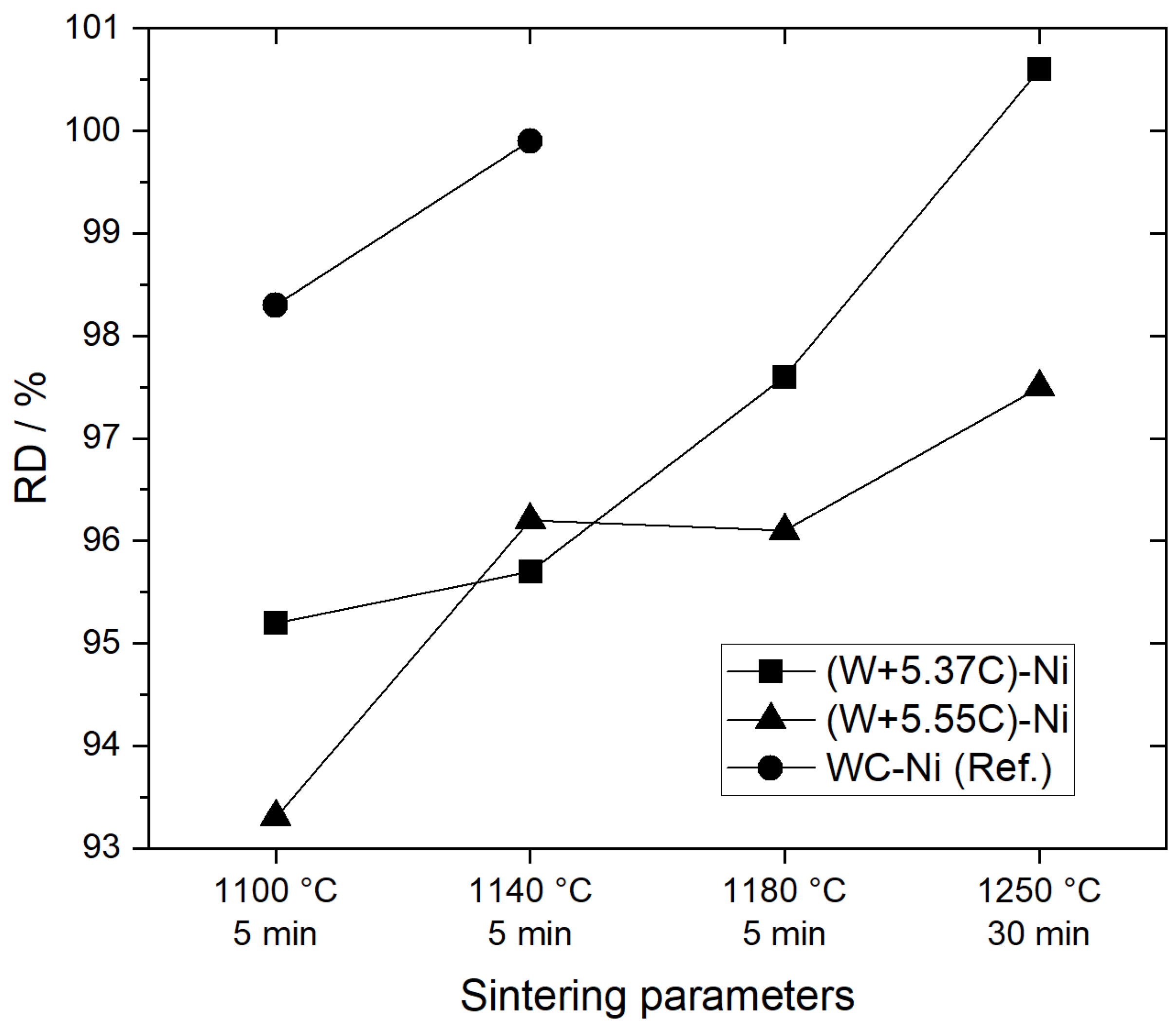
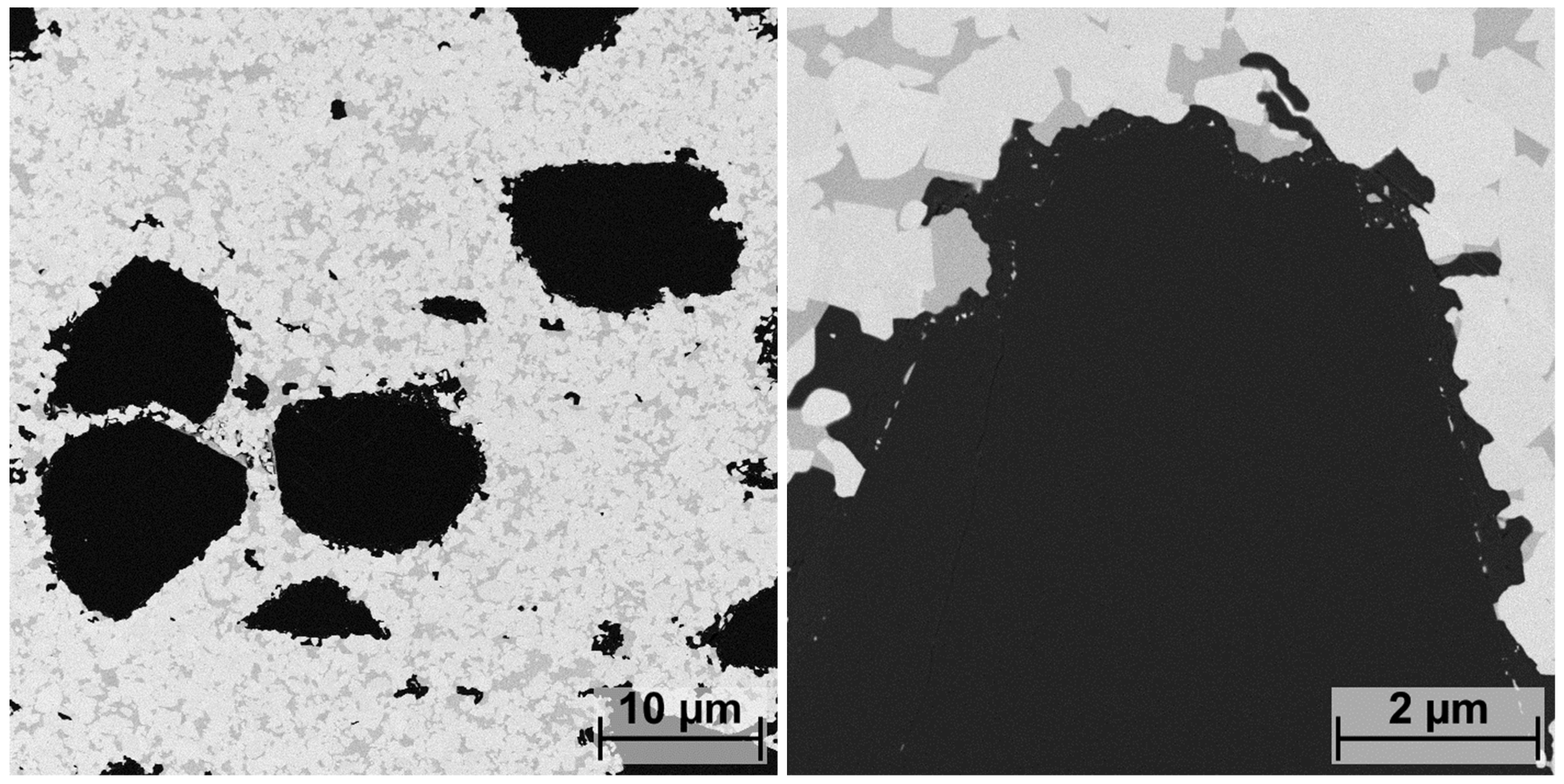
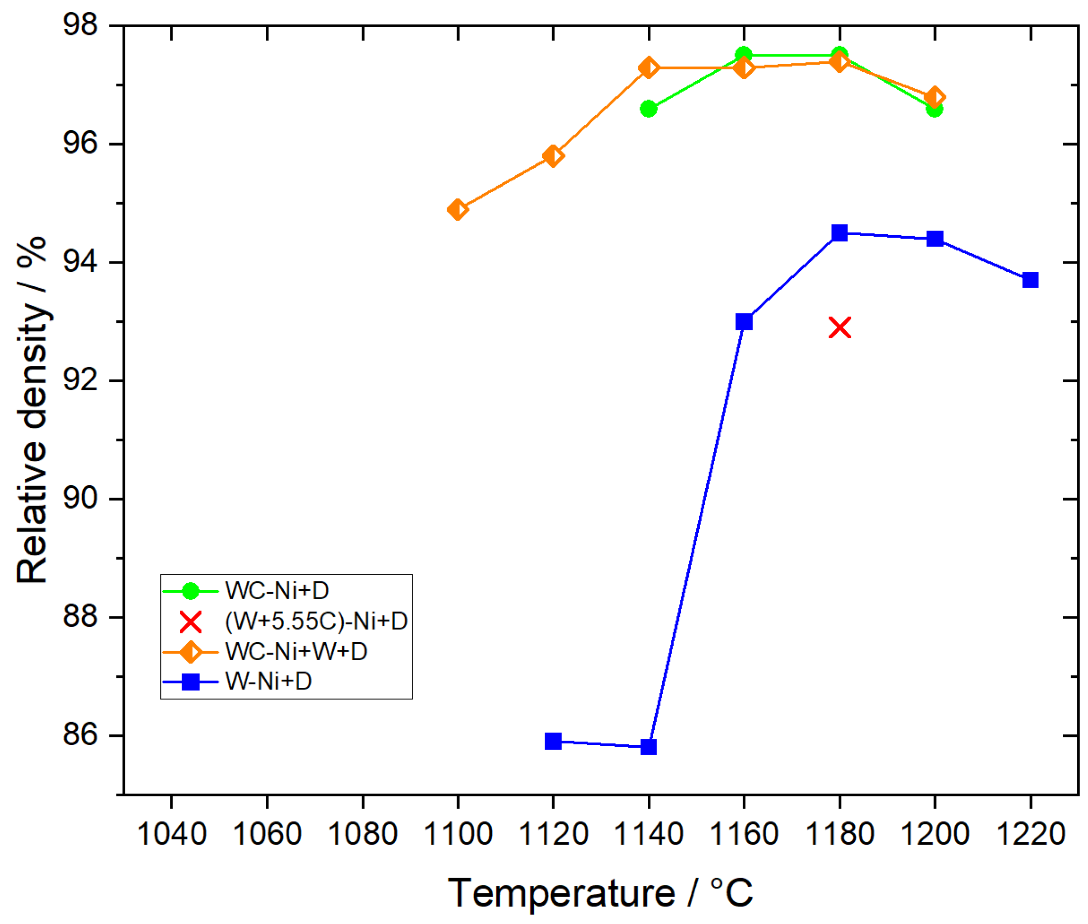
3.1. WC-Ni Hardmetal
3.2. DECC
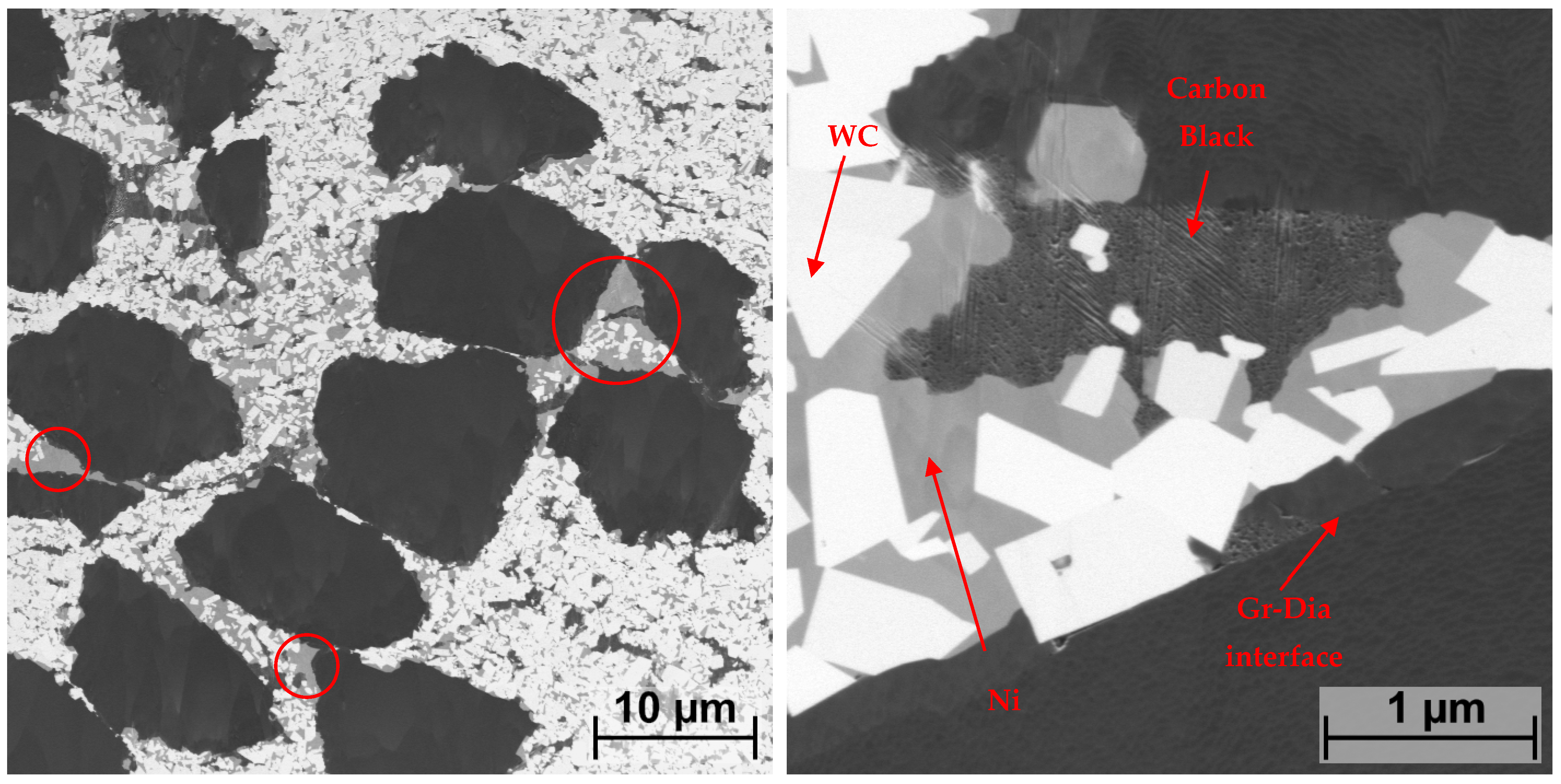
3.2.1. (W+5.55C)-Ni+D
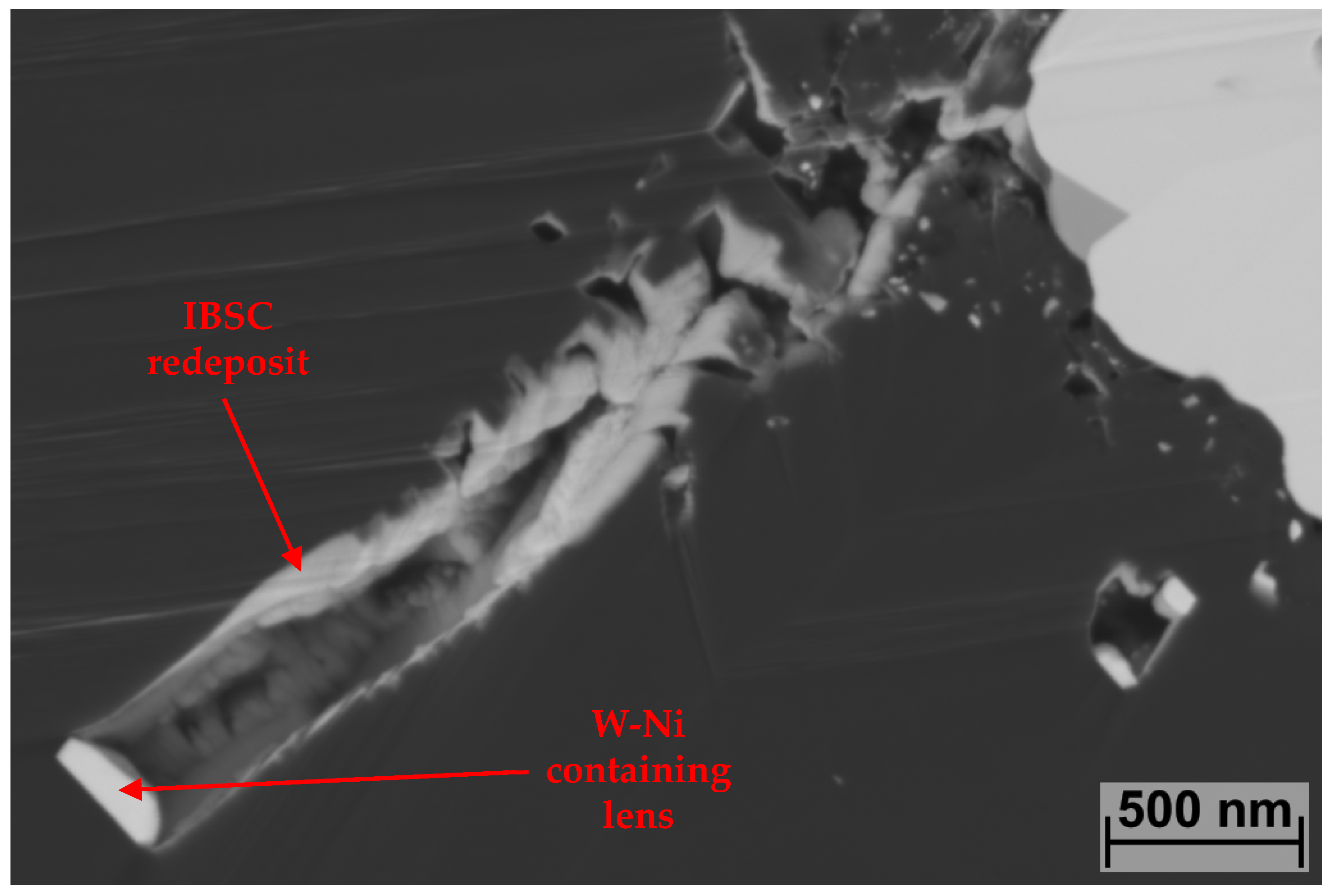
3.2.2. W-Ni+D
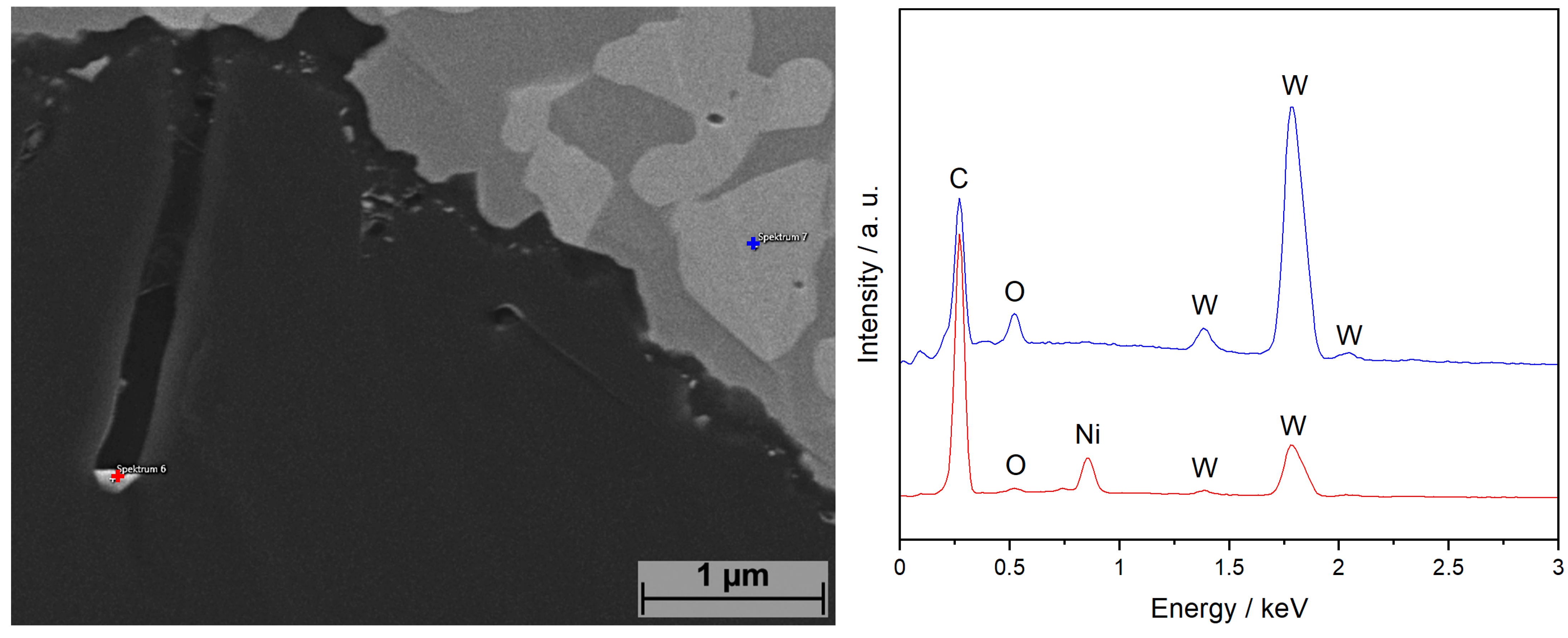
3.2.3. WC-Ni+W+D
4. Conclusions
Author Contributions
Funding
Data Availability Statement
Conflicts of Interest
References
- Konyashin, I.; Ries, B. Cemented Carbides; Elsevier: Amsterdam, The Netherlands, 2022; ISBN 9780128228210. [Google Scholar]
- Sarin, V.K.; Mari, D.; Llanes, L.; Nebel, C.E. Comprehensive Hard Materials: Volume 1–3: Hardmetals, Ceramics, Super Hard Materials; Elsevier: Amsterdam, The Netherlands; Waltham, MA, USA; Heidelberg, Germany, 2014; ISBN 9780080965284. [Google Scholar]
- Konstanty, J. Powder Metallurgy Diamond tools, 1st ed.; Elsevier: Amsterdam, The Netherlands; London, UK, 2005; ISBN 9781856174404. [Google Scholar]
- Gant, A.J.; Konyashin, I.; Ries, B.; McKie, A.; Nilen, R.; Pickles, J. Wear mechanisms of diamond-containing hardmetals in comparison with diamond-based materials. Int. J. Refract. Met. Hard Mater. 2018, 71, 106–114. [Google Scholar] [CrossRef]
- Shi, X.L.; Shao, G.Q.; Duan, X.L.; Xiong, Z.; Yang, H. The effect of tungsten buffer layer on the stability of diamond with tungsten carbide–cobalt nanocomposite powder during spark plasma sintering. Diam. Relat. Mater. 2006, 15, 1643–1649. [Google Scholar] [CrossRef]
- Moriguchi, H.; Tsuduki, K.; Ikegaya, A.; Miyamoto, Y.; Morisada, Y. Sintering behavior and properties of diamond/cemented carbides. Int. J. Refract. Met. Hard Mater. 2007, 25, 237–243. [Google Scholar] [CrossRef]
- Michalski, A.; Rosiński, M. Sintering Diamond/Cemented Carbides by the Pulse Plasma Sintering Method. J. Am. Ceram. Soc. 2008, 91, 3560–3565. [Google Scholar] [CrossRef]
- Wachowicz, J.; Wilkowski, J. Influence of Diamond Grain Size on the Basic Properties of WC-Co/Diamond Composites Used in Tools for Wood-Based Materials Machining. Materials 2022, 15, 3569. [Google Scholar] [CrossRef] [PubMed]
- Holke, R.; Richter, V.; Böhlke, W.; Weiland, F.; Barbier, G. Sintering of Diamond-Cemented Carbide-Composites; European Powder Metallurgy Association: Shrewsbury, UK, 2006; ISBN 1899072349. [Google Scholar]
- Grasso, S.; Hu, C.; Maizza, G.; Sakka, Y. Spark Plasma Sintering of Diamond Binderless WC Composites. J. Am. Ceram. Soc. 2012, 95, 2423–2428. [Google Scholar] [CrossRef]
- Spalden, M.v.; Pötschke, J.; Rosinski, M. Low Temperature Sintering of WC Based Diamond Enhanced Cemented Carbides with Novel Co-Free Binder Systems. In Proceedings of the World PM, Lyon, France, 9–13 October 2022. [Google Scholar]
- Ren, X.; She, D.; Peng, Z. Fabrication of diamond enhanced WC-Ni composites by spark plasma sintering. Int. J. Refract. Met. Hard Mater. 2022, 102, 105732. [Google Scholar] [CrossRef]
- Ke, Z.; Zheng, Y.; Zhang, J.; Zhang, G.; Wu, H.; Xu, X.; Zhou, W.; Zhu, X. Effect of WO3 content on microstructure and mechanical properties of dual-grain structured hardmetals fabricated by in-situ carbothermal reduction of WO3. Ceram. Int. 2020, 46, 20138–20143. [Google Scholar] [CrossRef]
- Joost, R.; Pirso, J.; Viljus, M.; Letunovitš, S.; Juhani, K. Recycling of WC-Co hardmetals by oxidation and carbothermal reduction in combination with reactive sintering. Est. J. Eng. 2012, 18, 127. [Google Scholar] [CrossRef]
- Amiri-Moghaddam, A.; Kalantar, M. In-situ synthesis of WC–X% Co composite in the WO3–Co3O4–C system by carbothermal reduction method. J. Aust. Ceram Soc. 2017, 53, 839–845. [Google Scholar] [CrossRef]
- Howard, S.M. (Ed.) Rapid Synthesis of Ultrafine WC-Co Cemented Carbides by In-Situ Reactions and Spark Plasma Sintering. In Proceedings of the Sessions and Symposia Sponsored by the Extraction & Processing Division (EPD) of the Minerals, Metals & Materials Society (TMS)—TMS 2008 Annual Meeting & Exhibition, New Orleans, LA, USA, 9–13 March 2008; TMS: Warrendale, PA, USA, 2008. ISBN 9780873397155. [Google Scholar]
- Liu, W.; Song, X.; Wang, K.; Zhang, J.; Zhang, G.; Liu, X. A novel rapid route for synthesizing WC–Co bulk by in-situ reactions in spark plasma sintering. Mater. Sci. Eng. A 2009, 499, 476–481. [Google Scholar] [CrossRef]
- Juhani, K.; Pirso, J.; Viljus, M.; Letunovitš, S.; Tarraste, M. The Influence of Cr3C2 and VC as Alloying Additives on the Microstructure and Properties of Reactive Sintered WC-Co Cermets. Mater. Sci. 2012, 18, 79–83. [Google Scholar] [CrossRef]
- Tarraste, M.; Juhani, K.; Pirso, J.; Viljus, M. Reactive Sintering of Bimodal WC-Co Hardmetals. Mater. Sci. 2015, 21, 382–385. [Google Scholar] [CrossRef]
- Tarraste, M.; Kübarsepp, J.; Mere, A.; Juhani, K.; Kolnes, M.; Viljus, M. Ultrafine Cemented Carbides with Cobalt and Iron Binders Prepared via Reactive In-situ Sintering. Solid State Phenom. 2021, 320, 176–180. [Google Scholar] [CrossRef]
- Tulić, S.; Waitz, T.; Čaplovičová, M.; Habler, G.; Varga, M.; Kotlár, M.; Vretenár, V.; Romanyuk, O.; Kromka, A.; Rezek, B.; et al. Covalent Diamond-Graphite Bonding: Mechanism of Catalytic Transformation. ACS Nano 2019, 13, 4621–4630. [Google Scholar] [CrossRef] [PubMed]


| Powders | Average Particle Size/µm | Manufacturer |
|---|---|---|
| WC | 1.4 | H.C. Stark Tungsten GmbH, Goslar, DE |
| W | 0.7 | Wolfram Bergbau und Hütten AG, St. Martin i.S., AT |
| C (Carbon Black) | 0.005 | Degussa GmbH, Düsseldorf, DE |
| Ni | 2.5 | Eurotungstene, Grenoble, FR |
| Diamond | 14–20 | Vollstädt Diamant GmbH, Seddiner See, DE |
| Designation | Content/w.% | TD/g/cm3 | |||||
|---|---|---|---|---|---|---|---|
| W | WC | C | Ni | Dia. | HM | HM + Dia. | |
| (W+5.37C)-Ni | 82.18 | - | 5.37 | 12.45 | - | 14.318 | - |
| (W+5.55C)-Ni [+D] | 82.05 | - | 5.55 | 12.40 | 9.74 | 14.318 | 11.079 |
| W-Ni [+D] | 86.85 | - | - | 13.15 | 14.39 | - | 11.079 |
| WC-Ni+W [+D] | 15.46 | 71.96 | - | 12.58 | 9.36 | - | 11.393 1 |
| WC-Ni [+D] (Ref.) | - | 87.55 | - | 12.45 | 9.53 | 14.318 | 11.079 |
| Specimen Designation | Sintering Parameters | C Loss/w.% |
|---|---|---|
| WC-Ni | 1140 °C, 5 min | 0.08 |
| (W+5.37C)-Ni | 1140 °C, 5 min | 0.20 |
| (W+5.37C)-Ni | 1180 °C, 5 min | 0.18 |
Disclaimer/Publisher’s Note: The statements, opinions and data contained in all publications are solely those of the individual author(s) and contributor(s) and not of MDPI and/or the editor(s). MDPI and/or the editor(s) disclaim responsibility for any injury to people or property resulting from any ideas, methods, instructions or products referred to in the content. |
© 2023 by the authors. Licensee MDPI, Basel, Switzerland. This article is an open access article distributed under the terms and conditions of the Creative Commons Attribution (CC BY) license (https://creativecommons.org/licenses/by/4.0/).
Share and Cite
Spalden, M.v.; Pötschke, J.; Michaelis, A. Novel Route for Preparing Diamond-Enhanced Cemented Carbides via Reactive Sintering. Metals 2023, 13, 1908. https://doi.org/10.3390/met13111908
Spalden Mv, Pötschke J, Michaelis A. Novel Route for Preparing Diamond-Enhanced Cemented Carbides via Reactive Sintering. Metals. 2023; 13(11):1908. https://doi.org/10.3390/met13111908
Chicago/Turabian StyleSpalden, Mathias von, Johannes Pötschke, and Alexander Michaelis. 2023. "Novel Route for Preparing Diamond-Enhanced Cemented Carbides via Reactive Sintering" Metals 13, no. 11: 1908. https://doi.org/10.3390/met13111908