Review

Analysis and Prospect of Precision Plastic Forming Technologies for Production of High-Speed-Train Hollow Axles

1
Faculty of Mechanical Engineering and Mechanics, Ningbo University, Ningbo 315211, China
2
Zhejiang Provincial Key Laboratory of Part Rolling Technology, Ningbo 315211, China
3
College of Mechanical and Automotive Engineering, Ningbo University of Technology, Ningbo 315211, China
*
Author to whom correspondence should be addressed.
Metals 2023, 13(1), 145; https://doi.org/10.3390/met13010145
Submission received: 24 November 2022 / Revised: 20 December 2022 / Accepted: 4 January 2023 / Published: 10 January 2023
(This article belongs to the Special Issue Rolling Process of Metallic Materials)

Abstract

:
The hollow axle is the key basic component of high-speed trains. How to realize its production with short process and high-quality precision plastic forming is the frontier of current research and a major problem to be solved. On the basis of analyzing the advantages and disadvantages of the existing forging process of the hollow axle, this paper expounds the principles and characteristics of multi-wedge synchrostep cross-wedge rolling (MSCWR) technology, multi-roll cross-wedge rolling (MCWR) technology, three-roll skew rolling (TRSR) technology, and tandem flexible skew rolling (TFSR) technology in detail, and discusses the feasibility and key technical problems of these technologies to form the hollow axle. It is concluded that tandem flexible skew rolling (TFSR) technology has the advantages of short process, high quality, high efficiency, energy saving, and material saving, and this technology is the development direction of precision plastic forming of the hollow axle. The research results provide technical guidance and research directions for promoting global high-speed rail development.

1. Introduction

High speed and heavy load are the long-term goals of high-speed transportation. The key to achieving these goals is the light weight of components. The hollow axle contributes an important part of being lightweight. It is a new axle structure, as shown in Figure 1. The hollow axle can not only meet the strength requirements of the axle, but also greatly reduce the unsprung weight of the train and improve the stability and safety of the train operation. Therefore, hollow axles are widely used in high-speed trains.
At present, the forming processes of hollow axle blanks include mainly open-die forging and radial precision forging. The open-die forging forming process is that the solid billet is forged with 2~4 arc anvils under the open-die forging machine at the same speed, and after one side is pressed down, it continues to be forged along the axis to make it form radially. This proceeds as the workpiece is fed along the axis until finally being formed. The working principle is shown in Figure 2a. After the solid axle is formed, the hollow axle meeting the requirements can be produced by drilling. Although the process of forming the hollow axle by open-die forging is simple, the forming quality is poor, in that the unilateral allowance is large (generally 10~15 mm), and the material utilization is low (58~65%). Moreover, the cost of subsequent finishing is high, and the production environment is poor (the noise is greater than 100 dB). At the same time, with the increase in billet size, the forging qualities such as ovality, machining allowance, axis offset, and internal quality are difficult to control. The radial precision forging forming process consists of conducting high-frequency radial forging of thick-wall hollow tubes through multiple hammers on a radial precision forging machine, and the hollow tube blank is circumferentially rotated and axially fed at a certain rate throughout the production process. The production of hollow-stepped shafts is realized by controlling the radial feed rate of hammers. Its working principle is shown in Figure 2b. The production line is characterized by two aspects, including equipment and process. The equipment mainly includes an annular heating furnace, a radial forging machine, a hot saw, a cooling bed, a typewriter, a heat treatment furnace, etc. In the process aspect, it is determined by the forming process data package consisting of both forging and heat treatment. As the core equipment of the production line, the radial forging machine is mainly designed and manufactured by GFM and SMS MEER, especially GFM, which has accumulated rich experience because of its early development of the radial forging machine. The SX series mechanical radial forging machine has stable and reliable performance, convenient maintenance, and low use cost. At present, most axle production lines based on the radial forging machine are manufactured by GFM, with its RF series being newly developed in recent years. This is a new type of radial forging machine driven by the main force machinery and driven by the hammer adjustment hydraulic system. On the other hand, SMS MEER developed the radial forging machine late, and its full hydraulic radial forging machine has a certain market among large tonnage radial forging machines because of its large reduction and good forging permeability [1]. Compared with the open-die forging forming process, the radial precision forging forming the hollow axle has better forming quality and higher production efficiency, and the forging processing precision is high, leaving only the finishing allowance, and the material utilization rate is high (65~73%). Although the radial precision forging process in forming the hollow axle has many advantages, the large radial precision forging machine technology limited by the forging force of more than 10 MN has been monopolized by a few manufacturers in developed countries, especially the large radial precision forging machine technology used in manufacturing high-end pipes such as the high-speed railway hollow axle, nuclear tube, and gun tube.
Industrial applications have proven that, although open-die forging and radial precision forging are the main processes for the production of train axles at present, these two processes still have a number of limitations, including adverse pollution, large investment, low efficiency, etc. Therefore, it is necessary to develop other forming processes. In recent years, scholars at home and abroad have carried out a lot of research on the forming process of the hollow axle, and have made some beneficial progress. To further enhance the development of this research, this paper points out the development direction of precision plastic forming of the high-speed train shaft by analyzing the principle and characteristics of multi-wedge synchrostep cross-wedge rolling (MSCWR) technology, multi-roll cross-wedge rolling (MCWR) technology, three-roll skew rolling (TRSR) technology, and tandem flexible skew rolling (TFSR) technology, the feasibility of forming the hollow axle by these processes and the key technical problems, and provides technical guidance and research directions for promoting the development of global high-speed railway.

2. Cross-Wedge Rolling Forming Technology of High-Speed-Train Axle

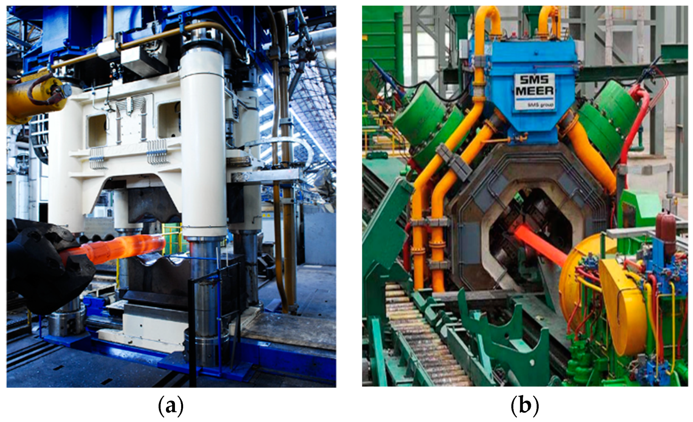
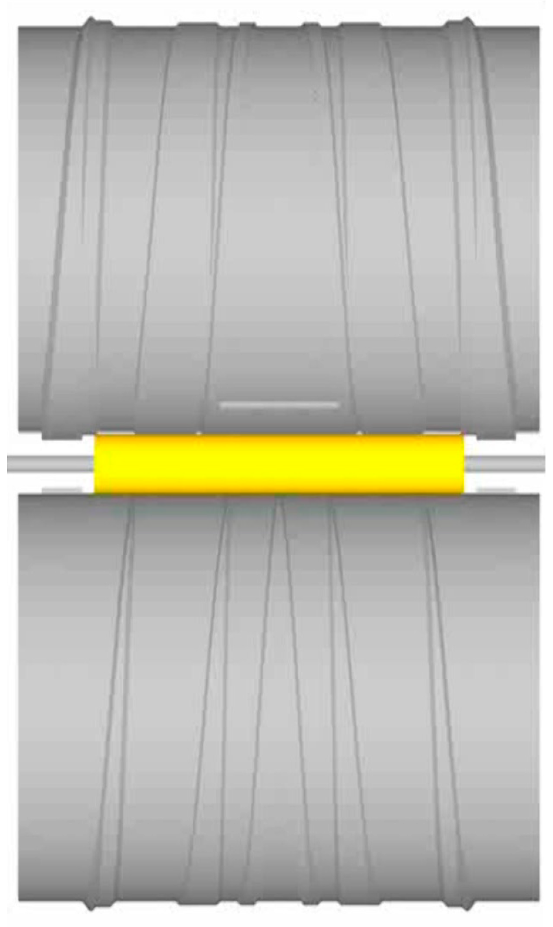
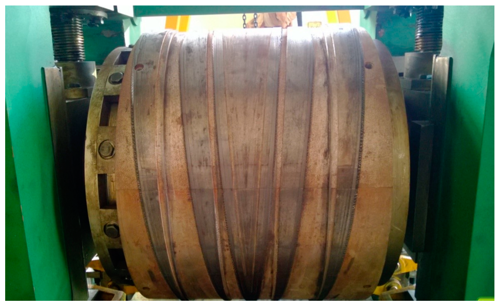
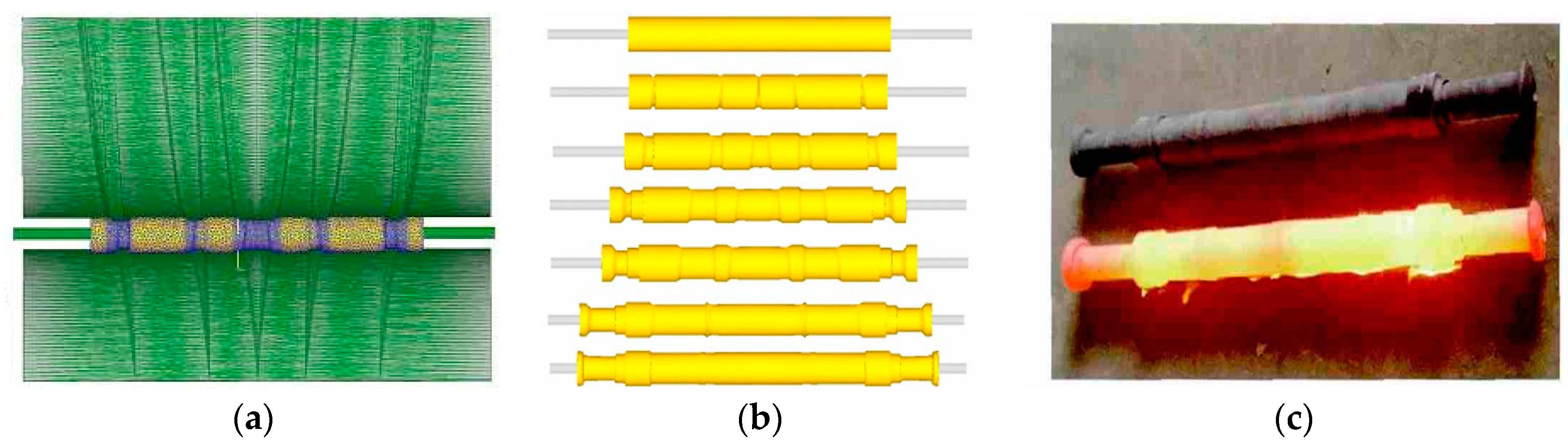
2.1. Multi-Wedge Synchrostep Cross-Wedge Rolling

Multi-wedge synchrostep cross-wedge rolling is a kind of advanced shaft part forming process [2] with multiple wedge-shaped dies simultaneously performing radial compression and axial extension of the rolled piece. Two multi-wedged rolls rotate in the same direction and drive the circular roller piece to rotate, as shown in Figure 3. The workpiece is rolled into shaft parts of various shapes and lengths under the action of the hole shape in the die, and subjected to external forces of the roll, namely, the radial rolling force P, the tangential friction force T, the axial force Q, and the axial friction force considering when the rolled piece is long. The continuous radial compression deformation of the rolled piece is maintained by the radial rolling force P that makes the radial compression deformation and the tangential friction force for rotation. The rolled piece is also subjected to an axial force Q, which promotes or prevents the rolled piece from extending. Under the action of these external forces, the deformation process and metal flow law inside the rolled piece are very complex, and there are complex mutual constraints between the wedges.
The advantages and disadvantages of cross-wedge rolling compared with the traditional forging process are shown in Table 1.
Rotating condition is the primary condition to determine whether the cross multi-wedge synchronous rolling hollow shaft can proceed smoothly. Figure 4 is the mechanical model, where (a) is the solid shaft, and (b) is the hollow shaft.
Based on the rotation condition of solid shaft multi-wedge rolling [3], Zheng et al. [4,5] calculated the rotation condition of hollow shaft multi-wedge rolling by considering the deformation characteristics, and obtained the stable rolling condition of the hollow shaft by introducing the concept of the plastic hinge and calculating the average unit positive pressure. These results laid an important theoretical foundation for hollow axle rolling by cross-wedge rolling.
Figure 4. Mechanical model of MSCWR: (a) solid shaft; (b) hollow shaft [5]. (Reprinted with permission from Ref. [5]. 2023, Springer Nature).
Metals 13 00145 g004
tan α tan β 2 d μ 2 nk π d k m 2 ( 1 + d D )
where α is the forming angle, β is the spreading angle, d is the diameter of the rolled piece, D is the roll diameter, μ is the friction coefficient, n is the wedge numbers, k is the instantaneous spread coefficient of the rolled piece (0 < k < 1), dk is the rolling radius, and m is the ellipticity parameter.
t μ b ( e μ b λ 1 ) < λ ξ ( 1 λ ) ( sin γ 2 γ π )
where t is the workpiece thickness, μ is the friction coefficient, b is the tangential width of the contact area, γ is the central angle of the contact area, ξ is the correction coefficient, and λ is the initial relative wall thickness of the rolled piece.
Li et al. established the finite-element model of a cross multi-wedge rolling railway RD2 axle in DEFORM.3D software. By analyzing the metal flow law and the internal stress state of the rolled piece when the three wedges are simultaneously wedged into the blank, it was found that when the process parameters are reasonably selected, the equal-section shaft section of the multi-wedge rolling is smoothly connected, avoiding the phenomenon of stress concentration during the transition connection, and the rolled axle is equivalent to the loose grade of the raw material. The above research results initially verify the feasibility of cross-wedge rolling railway axles [6].
By combining the finite-element simulation and experiment, Shu et al. found the optimal design parameters of the axle multi-wedge die (as shown in Figure 5) [2], and obtained the effect of process parameters on the stress of the railway axle by MSCWR. A three-dimensional rigid-plastic finite-element model of the MSCWR was established, and the influence law of the die process parameters such as the spreading angle on the force and energy parameters of the hollow axle was analyzed. The 1:5 multi-wedge rolling hollow axle experiment was carried out, and the relative error between the experimental rolling torque and the numerical simulation results was within 10 %. The correctness of the finite-element model is verified [3,7].
Zheng et al. established a rigid-plastic FE model of MSCWR in DEFORM-3D, and explained the deformation mechanism and forming process. After that, a 1:5 ratio hollow axle was rolled by a cross-wedge rolling mill (as shown in Figure 6). It can be seen from the figure that the finished hollow axle has a satisfactory imaging quality, which verifies the accuracy of the proposed FE model [5]. Huang et al. established the mathematical model of the deflection angle of the hollow axle by MSCWR, and obtained the deflection angle of each wedge of the hollow axle by MSCWR, which provided a method for selecting the deflection angle, and can be used as a reference for the design of multi-wedge die [8]. The above research results provide a theoretical basis for promoting cross multi-wedge synchronous rolling technology, realizing the efficient material-saving production of railway axles, and improving the quality.

2.2. Multi-Roll Cross-Wedge Rolling for High-Speed-Train Axle

Pater et al. proposed a variety of ideas for cross-wedge rolling of railway axles, one of which consists of forming the axle in two steps with two sets of rolls (as shown in Figure 7). The first step includes forming the central step, while the other step involves forming the end step of the railway axle. The FE simulation results(as shown in Figure 8 and Figure 9) show that the load and torque of the process are low, and the process can prevent material cracking in the axial area [9].
In addition, the hollow axle is rolled by the three-roll cross-rolling process by using a specific roll shape. The three rolls are distributed at 120° in the circumferential direction of the rolled piece (as shown in Figure 10). The formation of cracks in the rolling process is analyzed, and the wall thickness variation law, equivalent strain (as shown in Figure 11), distribution of damage (as shown in Figure 12) and temperature distribution of the rolled piece are determined, as well as the rolling mill power required to produce hollow axles by this process. These new ideas break through traditional thinking and provide a new idea for the cross-wedge rolling train axle [10].

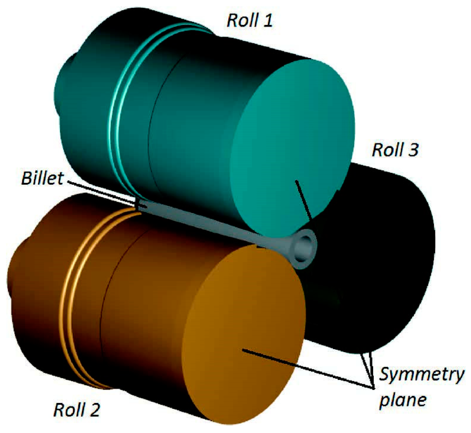
3. Three-Roll Skew Rolling Technology for High-Speed Train Axle

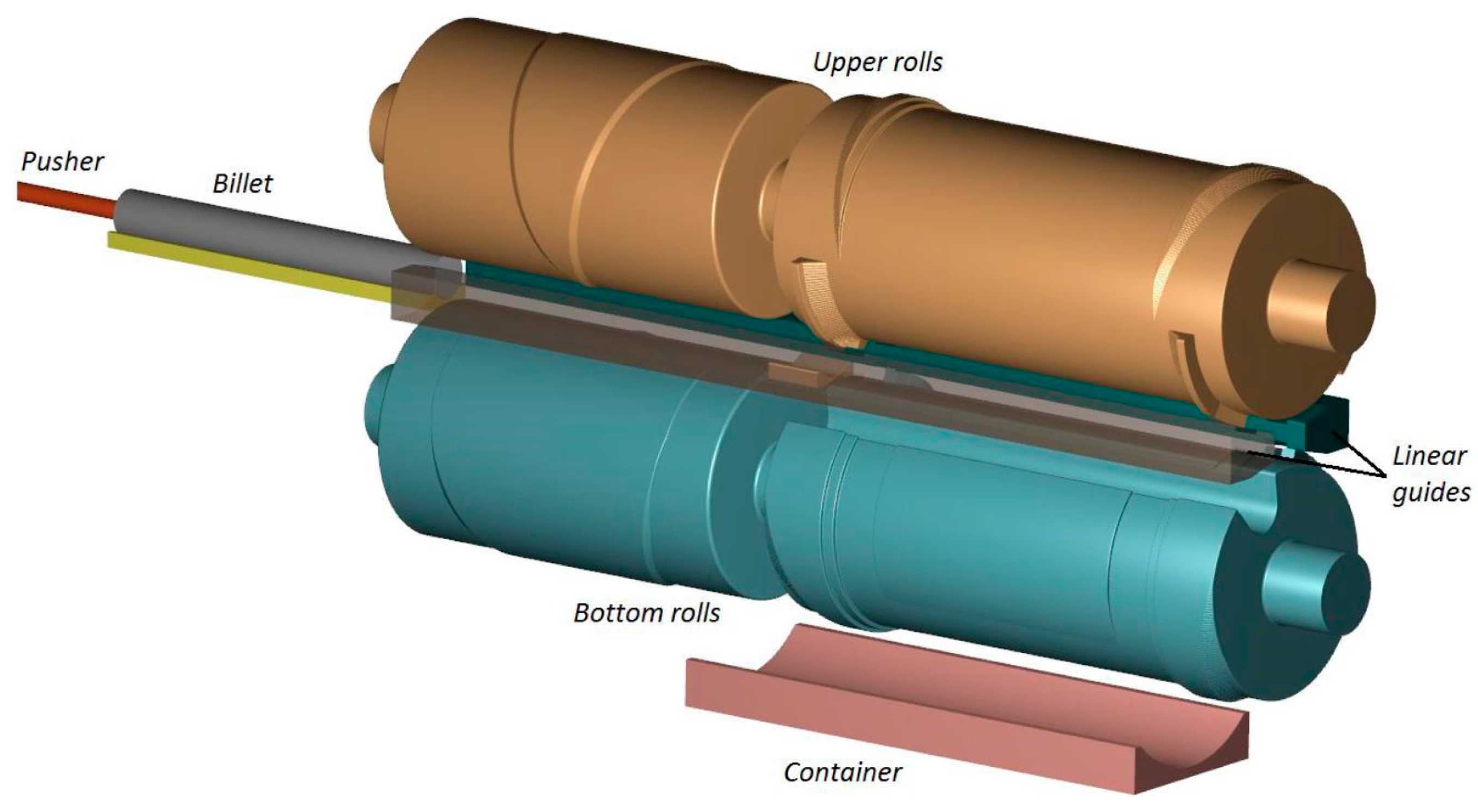
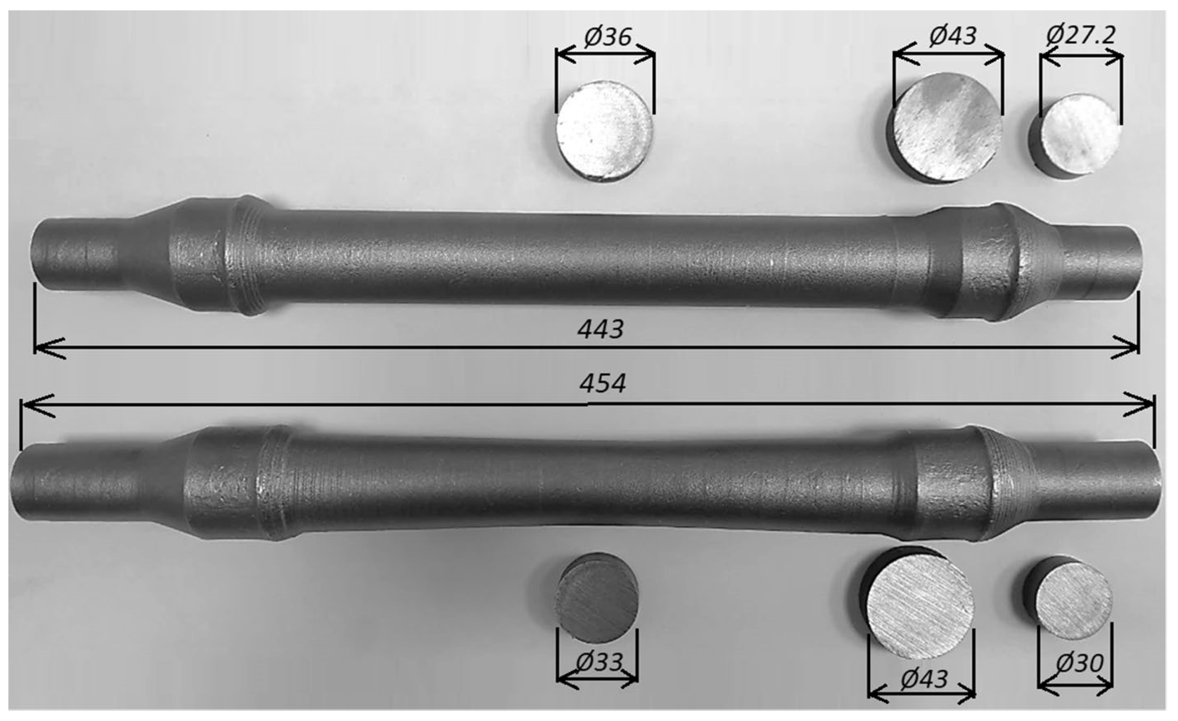
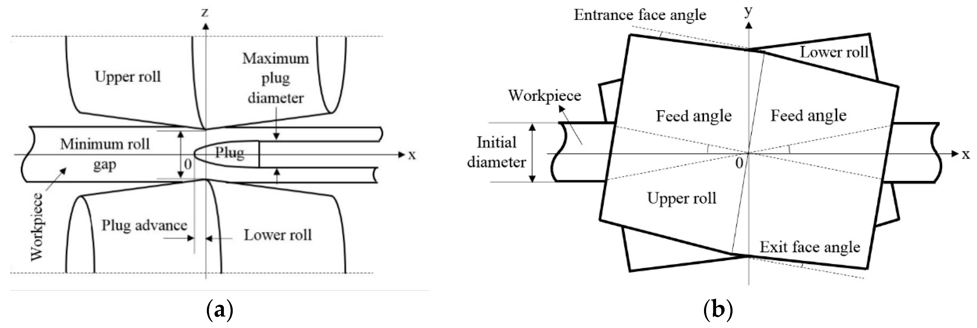
3.1. Forming Principle of Three-Roll Skew Rolling Shaft Parts

Shu et al. proposed to use the three-roll skew rolling method to produce the high-speed train hollow axle, and carried out systematic research on it [11], pointing out that the three-roll skew rolling process belongs to the local loading axial continuous plastic forming technology. The principle is shown in Figure 13. Three disc rollers are distributed 120° around the blank, and the roller axis and the blank axis deflect at a certain angle (deflection angle). During rolling, the three rollers rotate in the same direction synchronously to drive the rolled piece to rotate reversely. At the same time, the rolled piece is driven by the clamp to move along the axial direction, and the three rollers feed radially synchronously to achieve the formation of the stepped shaft.
Zhang and Pater made many contributions to the velocity vector analysis of the deformation zone of the rolled piece during stable rolling, as shown in Figure 14 [13,14]. Point O is defined as the rotation center of the roller around the rotation when the feed angle is adjusted, and the vertical line of the rolling line (the rolling line is generally coincident with the axis of the rolled piece) is the rotation axis. The plane composed of the rotating axis and rolling line is the main rolling plane, and the plane composed of the rotating axis and roller axis is the main roller plane. Taking any point P in the deformation zone as the coordinate origin, the crossing point P is the x-axis along the rolling direction, the crossing point P is the y-axis along the tangential direction of the rolled piece, and the vertical line of the crossing point P as the rolling line is the z-axis. The A-A view is the projection along the rolling direction perpendicular to the main plane of the rolling, and the B-B view is the projection along the roll axis perpendicular to the main rolling plane. β is the feed angle, γ is the angle between the z-axis and the main rolling plane, and j is the angle between the line connecting the P point and the roller axis (the roller radius passing the P point) and the main plane of the roller.
At the stable rolling stage, the point O is set at the interface between the roller and the rolled piece, and the point P is located on the rotation axis of the roller. The relationship between the roller rotation speed nb and the rolled piece rotation speed nr can be expressed as:
n b = ρ max r a n r η y cos β
where ρmax is the maximum radius of the roller, ra is the exit section radius of the rolling deformation zone of the rolled piece, and ηy is the tangential slip coefficient of any point P in the deformation zone of the rolled piece, and its axial slip coefficient ηx is selected from the measured value or empirical value, ranging from 0.5 to 1.3 [15].
The lead Zx and pitch zx of the rolled piece along the rolling direction are:
Z x = 60 u x r a ρ max n r η y cos β
z x = 20 u x r a ρ max n r η y cos β
It can be seen from Equations (4) and (5) that the method of controlling the pitch of the rolled piece to be equal or less than a certain value in the variable diameter section of the rolled piece consists of adjusting the axial traction speed of the fixture or the rotational speed of the roller. In the diameter-increasing section, it is necessary to reduce the axial traction speed of the clamp or increase the roller rotation speed. In the diameter-reducing section, it is necessary to increase the axial traction speed of the clamp or reduce the roller rotation speed.
The advantages and disadvantages of TRSR compared with the traditional forging process are shown in Table 2.

3.2. Feasibility Analysis of Three-Roll Skew Rolling Axle

Pater et al. verified the feasibility of three-roll skew rolling light truck spindles, laying an important foundation for subsequent research [12]. Later, Pater et al. conducted a lot of research on the feasibility of applying this technology to the rolling of the train axle, including finite-element simulation of the process of rolling the train axle with the three-roll skew rolling process, and analysis of the temperature field and strain field of the train axle (as shown in Figure 15 and Figure 16). It was found that the train axle has good forming quality, the strain mainly occurs on the surface of the axle, and the temperature of the rolled piece is always in the appropriate range during the rolling process [16]. Xu et al. proposed to apply this technology to the production of the high-speed train hollow axle, clarified the forming mechanism of the process, and theoretically proved the influence of process parameters on the force and energy parameters [17,18]. Wang et al. analyzed the influence of process parameters on the average grain size and microstructure uniformity of the rolled piece. The results showed that the grain size was obviously refined and the distribution was relatively uniform. The optimum rolling temperature is 1050 °C, the optimal deflection angle is 9°, and the optimal roller rotation speed is 90 rad/min [19].
Pater et al. tried a 1:5 scale train axle using a CNC three-roll skew rolling mill (as shown in Figure 17). From the experimental results, it can be seen that the spiral lines and stacking appeared on the axle surface. In response to this defect, the impact was evaluated. Then, through the optimization of process parameters, the occurrence of spiral pattern and stacking phenomenon was effectively controlled [20,21,22]. Through rolling experiments, Shu et al. found that the grain size of the rolled piece gradually increases from the outer surface to the inner surface. It can be seen that at higher rolling temperatures, the initial grain size and the final average grain size are larger than that at lower temperature (as shown in Figure 18, Figure 19 and Figure 20). By increasing the axial traction speed, not only can the rolling time be shortened, but the coarse grains can also be avoided. Therefore, the mechanical properties can be improved [23].

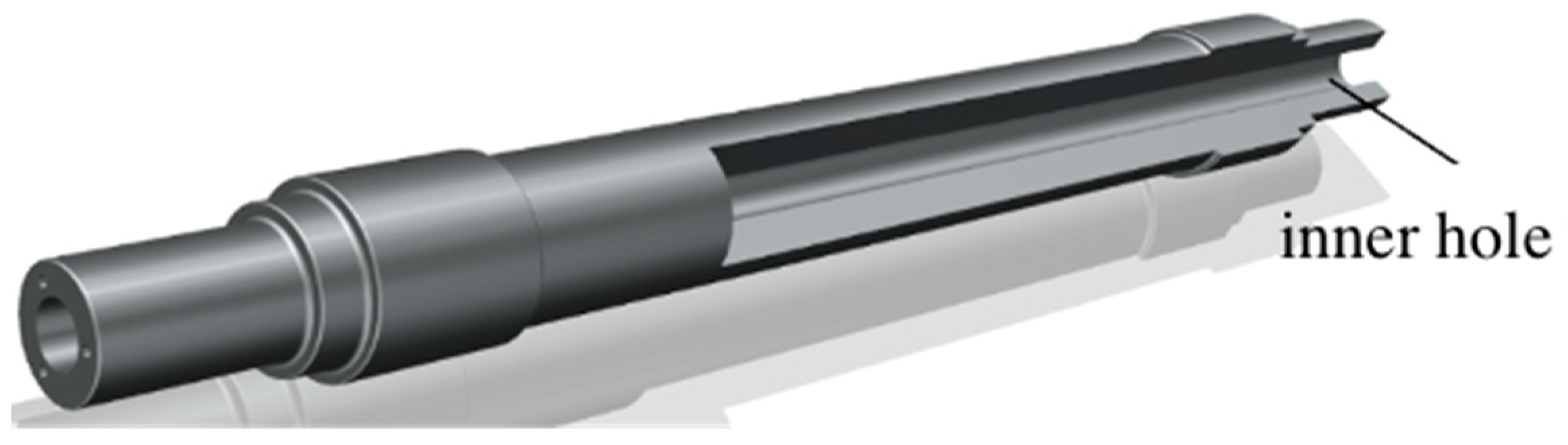
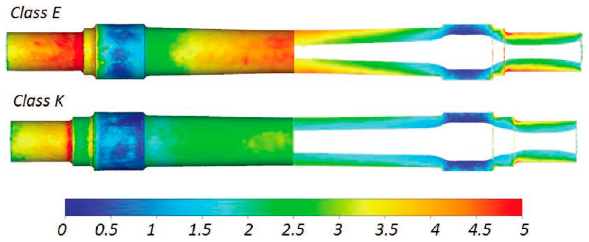
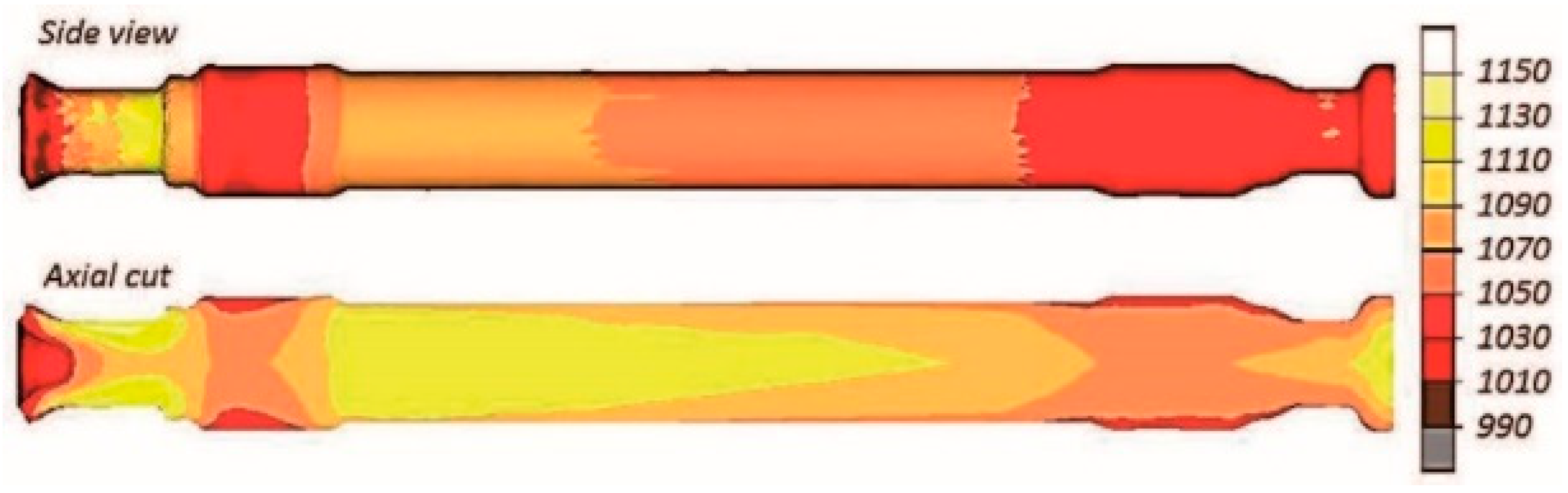
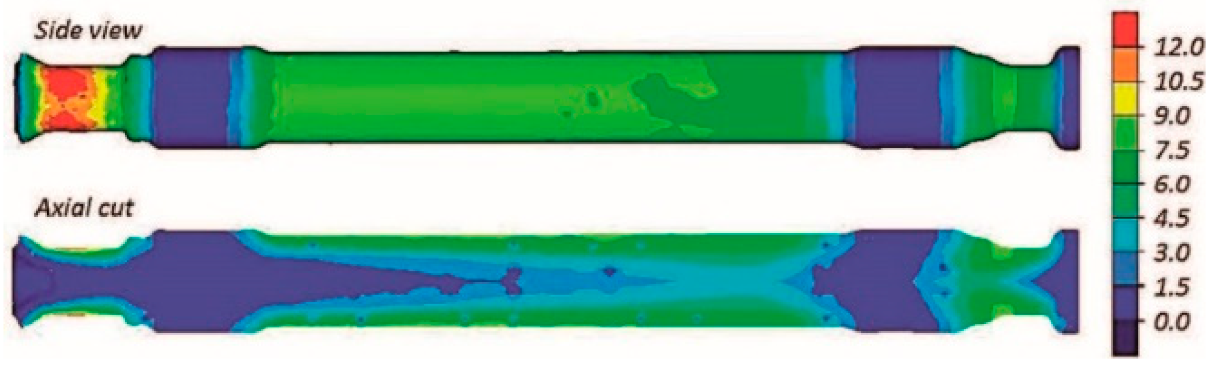
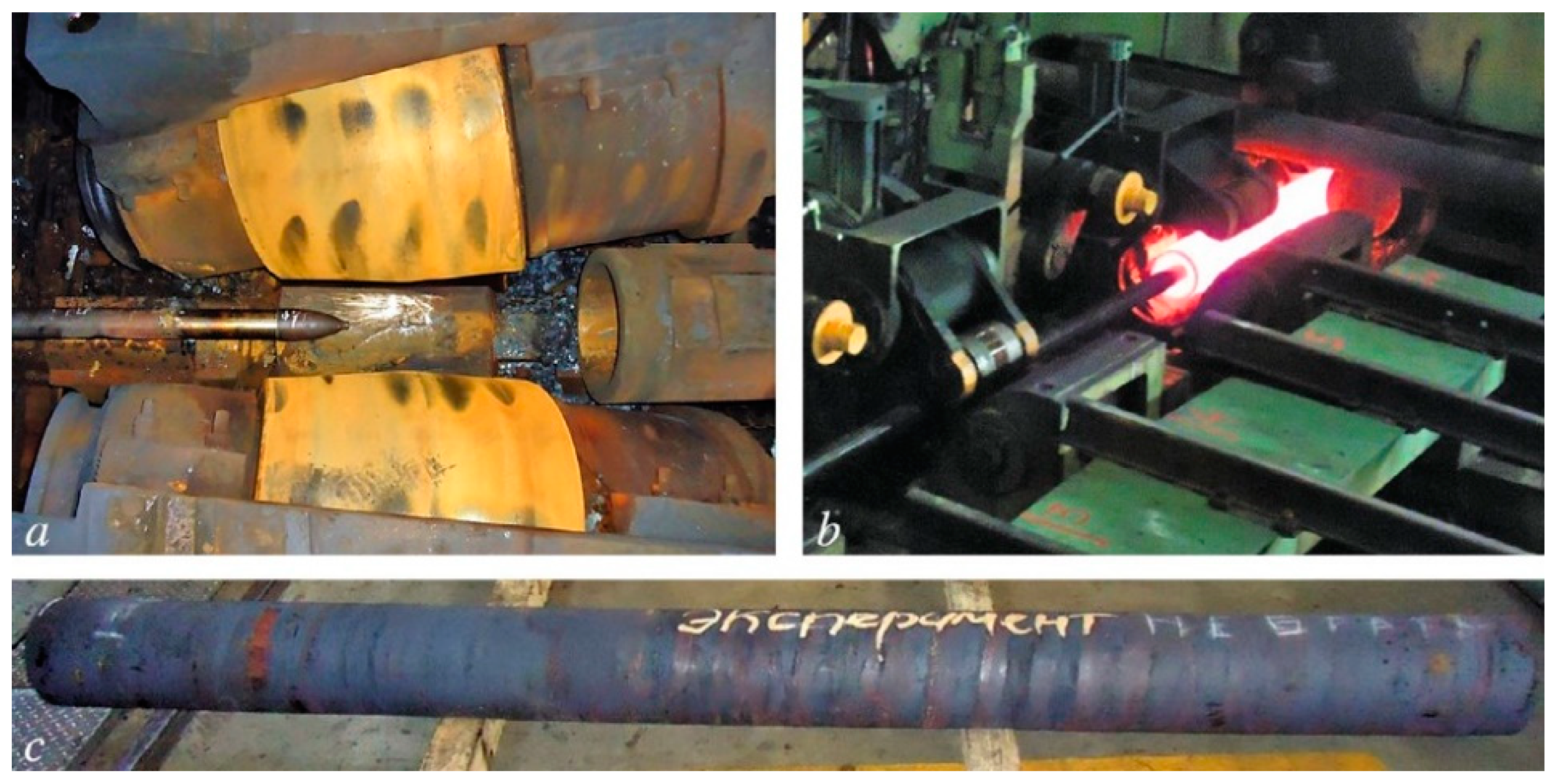
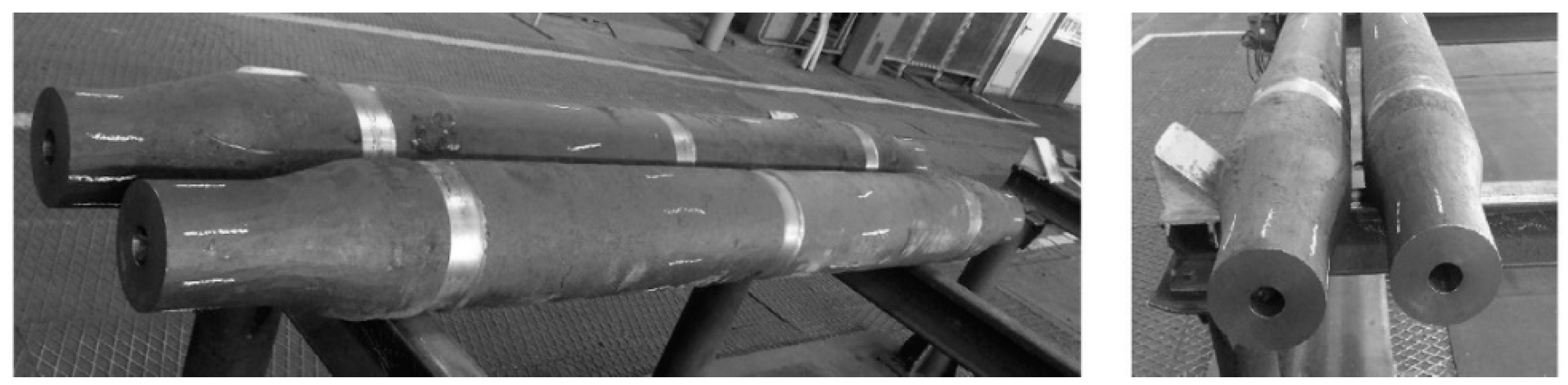
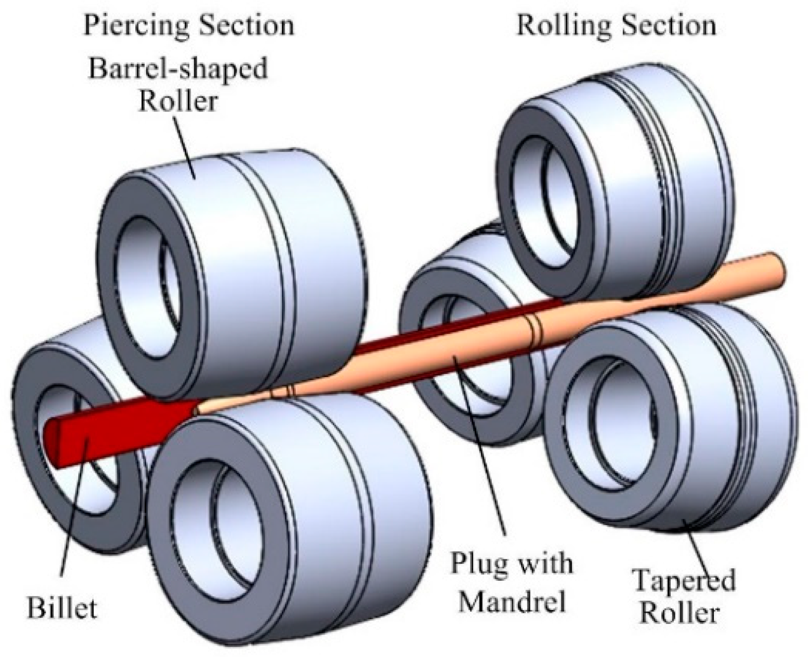
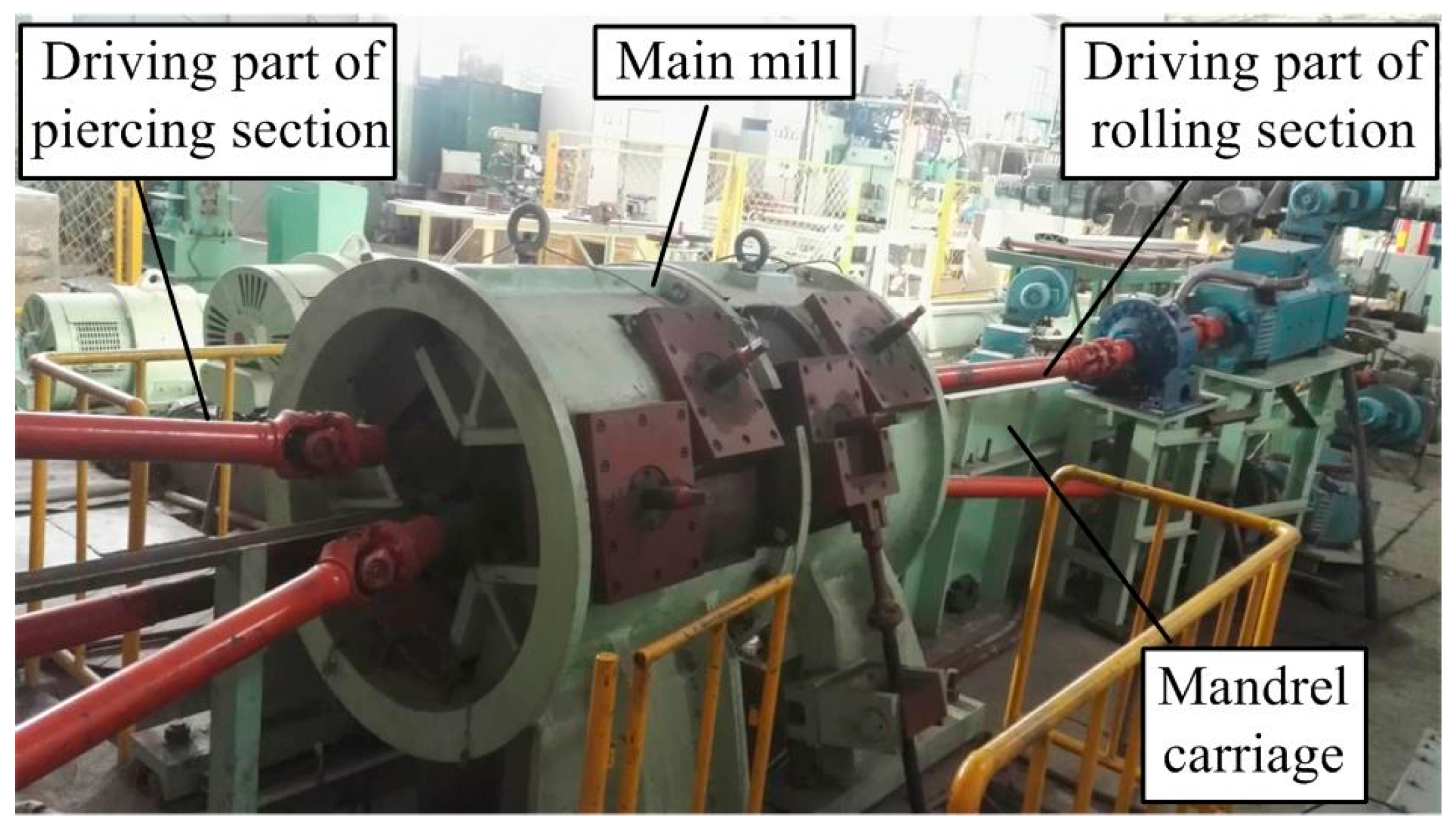
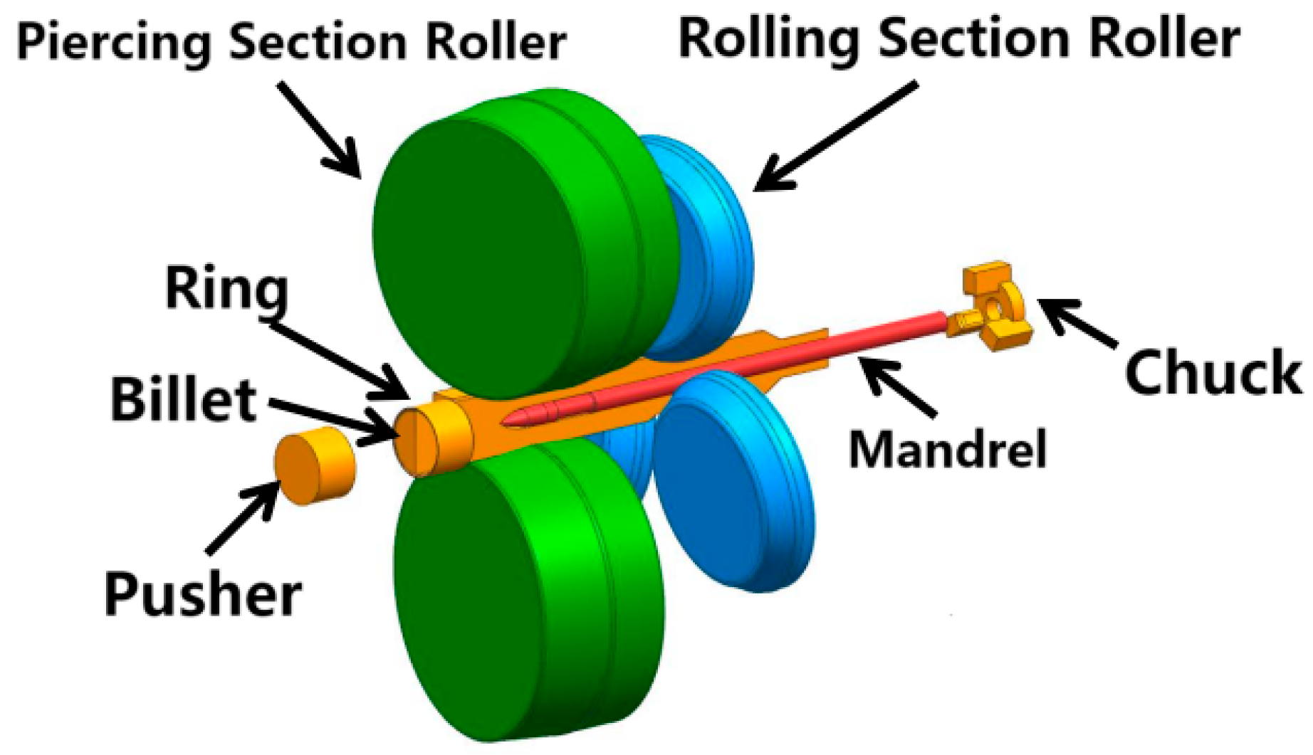
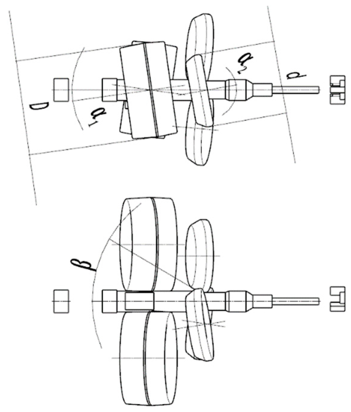
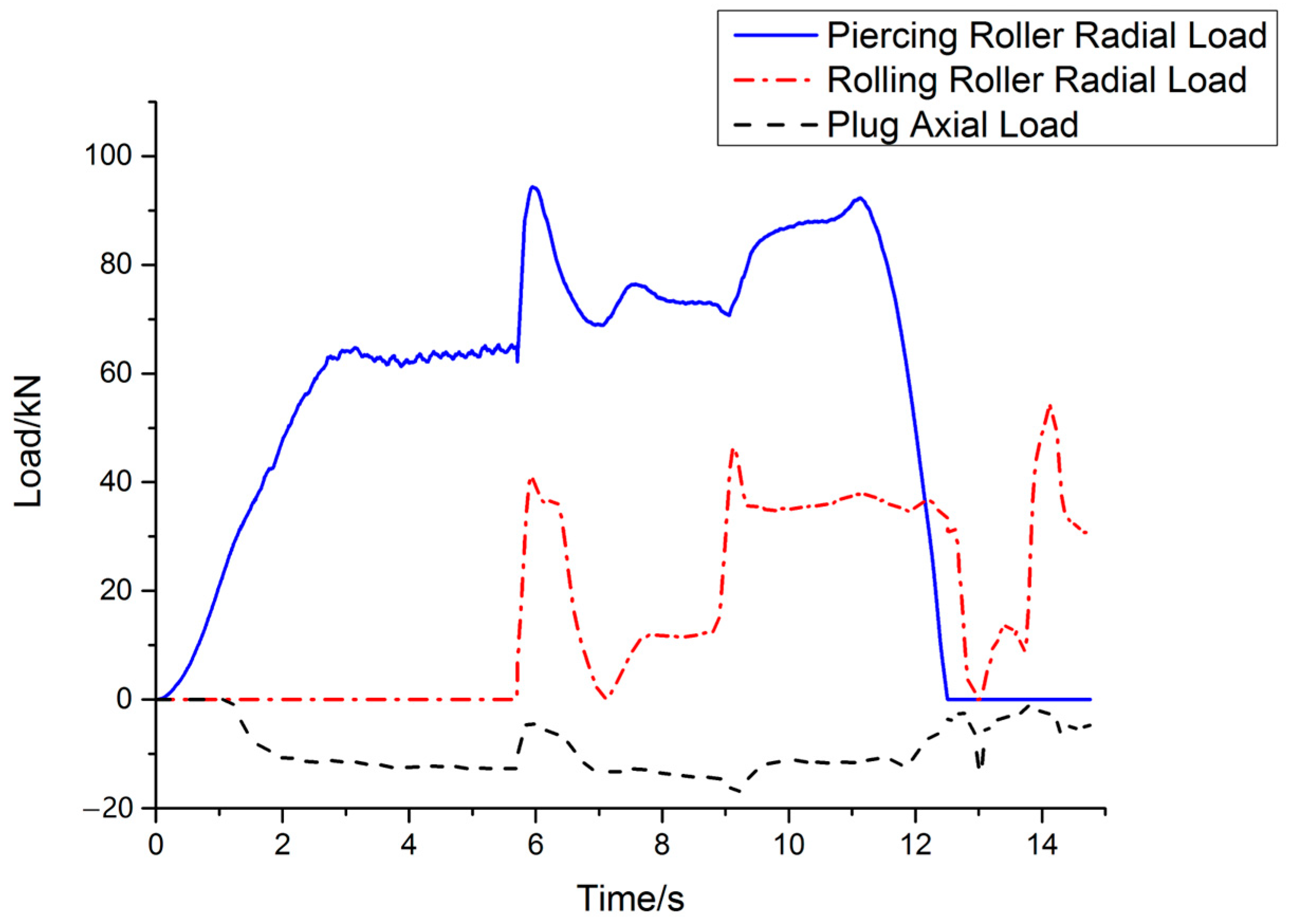
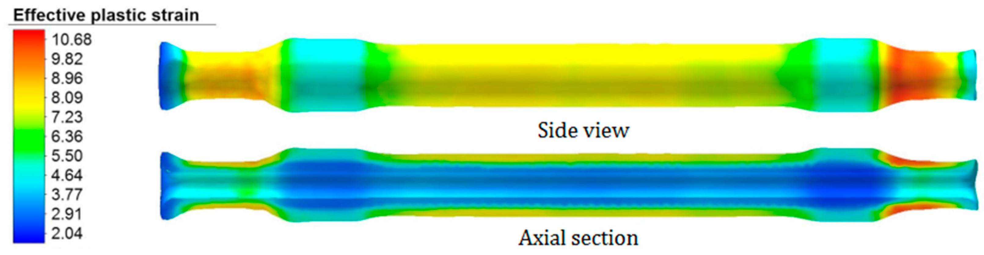
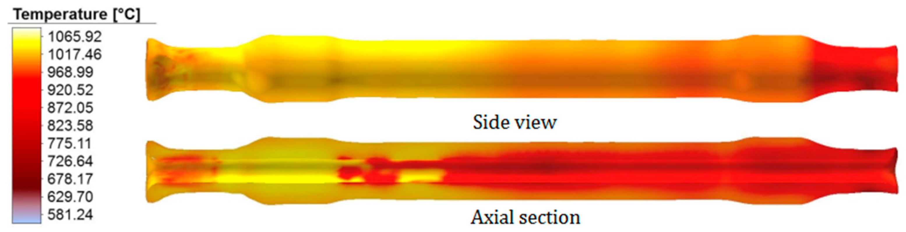
4. TFSR Technology of Hollow Axle

4.1. Two-Roll Rotary Piercing

Because the machining process of the hollow axle inner hole is very complex and inefficient, and the required equipment is very expensive, many internal hole machining alternatives have also been proposed, especially rotary piercing. Rotary piercing refers to the process in which two or three rolls with the same rotation direction bite the heated tube blank (the center line of the piercing and the center line of the roll form a certain spatial intersection relationship), and the solid tube blank is threaded into a blank under the interaction of the roll and the plug. The rotary piercing actually uses the cracked and unbroken loose state of the metal in the core area of the tube blank under the action of the piercing tool to place the plug in the loose area for piercing, as shown in Figure 21.
Compared with the traditional machining hollow axle bore, the rotary piercing process has the following advantages: Since the step of cutting the inner hole is omitted, this process can reduce steel consumption and save about 100 kg of materials. The rotary piercing reduces the difficulty of machining and saves the cost of boring. The tube rolled by this process is more compact, the fiber flows along the rolling direction, and the main working stress is perpendicular to the fiber distribution direction, which is conducive to improving its working stress and fatigue life.
Yuanrui et al. obtained 35CrMo super-thick-wall seamless steel pipes of a certain size with a Pilger mill. After analyzing the metallographic structure and mechanical properties and conducting other tests on the seamless steel pipes, it was confirmed that the quality of this batch of steel pipes met the technical requirements for hollow axle blanks [25]. Romanenko et al. studied the method of preparing hollow axle blanks for railway vehicles by using a two-roll rotary piercing machine, carried out experimental rolling in the rolling device (as shown in Figure 22 and Figure 23), and compared the mechanical properties of the hollow axle and the solid axle. It was found that the average impact strength and minimum impact strength of the hollow axle produced by this method were 34.6% and 63.2% higher than the GOST standard [26,27] respectively. Smk et al. analyzed the stress and deformation state of the axle blank with the roll feed angles of 6° and 12°, and found that the stress intensity distribution in the longitudinal section is uneven, and the maximum stress appears at the end of the mandrel and the extrusion area. When analyzing the deformation state of the rolled piece under a large feed angle, the surface of the rolled piece was found to form spiral stripes [28].

4.2. Tandem Skew Rolling

Tandem skew rolling is a new process for hot rolling seamless steel tubes (Figure 24 and Figure 25), which is suitable for rolling metal materials with small rolling temperature intervals and difficulty in deformation [29]. This process is a multi-step process of piercing and rolling on two groups of rolls. The principle diagram of tandem skew rolling is shown in Figure 26. This process is proposed on the basis of the three-roll combination piercing process [30,31]. Fujie et al. [32,33] put forward the tandem skew rolling and expounded the forming mechanism of the process. Feilong et al. [34,35,36] analyzed the kinematics of the forming process and carried out tandem skew rolling experiments on hard deformed metals such as AZ31 magnesium alloy, 42CrMo high-strength steel, TC4 titanium alloy, etc., by using a tandem skew rolling machine.

4.3. Tandem Flexible Skew Rolling

Tandem flexible skew rolling of the hollow axle refers to the two processes of rotary piercing and rolling the stepped axle, which are completed in one stage. There are two sets of rolls in this process, namely, piercing roll and disc roll, which are used to form the inner hole and stepped axle, respectively (as shown in Figure 27). The working principle of this process is: first, the billet is pushed by the pusher to the deformation area of the piercing part and bitten by the piercing roll. After passing through the deformation area of the piercing part, the billet becomes a capillary, then the capillary reaches the rolling deformation area and is bitten by the disc roll. The capillary is rolled into a stepped shaft with a certain size through the radial movement of the roll. When the whole workpiece passes through the deformation area of the piercing part, the chuck behind the disc roll will bite the workpiece and make the axial move at a certain speed with the radial speed of the disc roll until the rolling process is completed.
Compared with the traditional manufacturing process of the hollow axle blank, the tandem flexible skew rolling technology of the hollow axle has the following advantages: locally loaded axial continuous forming; the rolled parts are placed outside the equipment, significantly saving the rolling space of the equipment, reducing the size of the equipment body, and solving the problems of large forming contact area; large forming force; large and complex dies; large and complicated equipment costs; etc. The problem that the rolled piece size is limited by the die size in the traditional process forming is overcome. Dieless flexible forming integrates the forming manufacturing technology with digital technology and automation technology. Through multi-degree of freedom active control of tooling and variable roll pitch, it can flexibly realize the precision forming of different shape steps of axles. It can quickly respond to manufacturing needs and solve the problems of the high cost of die processing, long die adjustment/repair cycle, and large die storage space requirements existing in traditional die forming manufacturing technology. The inner hole and shape of the hollow axle are formed synchronously. Because tandem flexible skew rolling consists of completing the inner hole forming and step shaft forming in one process, it is not needed to drill the inner hole separately in the later stage, which avoids unnecessary waste of materials and effectively improves the utilization rate of materials.
The advantages and disadvantages of TFSR compared with the traditional forging process are shown in Table 3.
As shown in Figure 28, the piercing roll and disc roll are, respectively, aligned with the central axes α1 and α2, where α1 can be taken within 7°~10°, and α2 can be taken from 8° to 12°. It is understood that there must be a continuous rolling relationship between the two sets of rolls in the process of rolling hollow axles. At this time, the metal flow in the deformation zone of the two sets of rolls needs to meet the rule of volume flow rate, namely:
Δ 1 = Δ 2
F 1 v 1 = F 2 v 2
where ∆ is the metal second flow volume of the two stands, F is the cross-sectional area of the rolled piece at the outlet of the two stands, and v is the exit speed of the rolled piece of the two stands.
Caoqi et al. [37] creatively put forward tandem flexible skew rolling on the basis of tandem skew rolling, clarified the value range of the tandem flexible skew rolling deflection angle of two sets of rolls and the principles to be followed, simulated the process of rolling the hollow axle with finite-element software, and analyzed the change law of force parameters in the rolling process, as well as the strain and temperature distribution of the rolled axle blank (Figure 29, Figure 30 and Figure 31), The simulation results verify the feasibility of rolling the hollow axle with this technology, and lay a theoretical foundation for the short process of forming hollow axle blanks.

5. Conclusions and Outlook

5.1. Conclusions

  • The structure and performance of the hollow axle formed by radial precision forging are fine, but the process is long, the investment is large, the efficiency is low, and the core technology is monopolized by some companies;
  • Although cross-wedge rolling has the advantages of high efficiency, material saving, and energy saving, it is difficult to industrialize due to the complexity and huge size of dies, high equipment cost, etc.;
  • Three-roll skew rolling can realize the dieless forming of the train shaft profile, but for solid billets, the deep hole process needs to be added after forming the profile, which still cannot solve the problem of the short process;
  • Tandem flexible skew rolling has the advantages of dieless flexible forming and integrates the forming manufacturing technology with digital technology and automation technology and synchronous forming of the inner hole and shape of the hollow axle. Because tandem flexible skew rolling consists of completing the inner hole forming and step shaft forming in one process, it is not needed to drill the inner hole separately in the later stage, which avoids the unnecessary waste of materials and effectively improves the utilization rate of materials. However, the coordination of two sets of roll speeds is an urgent problem to be solved.

5.2. Outlook

Tandem flexible skew rolling is the best process for forming hollow train shafts with short process and high quality, and is the development direction for realizing high-quality manufacturing of high-speed train shafts. However, how to match the rotating speeds of two sets of rolls during stable and coordinated rolling is the key and difficult point of this technology. Therefore, future research should focus on the following two points: the exploration of the shape coordination control mechanism under the piercing composite forming process and the exploration of the interaction mechanism of the piercing process. Facing the future, the establishment of an intelligent decision-making platform for axle piercing synchronous forming and the establishment of an ultrasonic flaw detection mechanism under high temperature are also necessary conditions for realizing short process and flexible digital precision forming of the high-speed train axle. These studies can provide technical support for establishing a digital high-quality forming production line for hollow axles.

Author Contributions

Conceptualization, X.S.; methodology, X.S. and C.Y.; software, C.Y.; validation, J.W. and Y.X.; formal analysis, S.Z. and Y.D.; writing—original draft preparation, X.S. and C.Y.; writing—review and editing, X.S.; supervision, Y.W. and H.X. All authors have read and agreed to the published version of the manuscript.

Funding

This study was funded by the Natural Science Foundation of Zhejiang, China (Grant Number: LZ22E050002), the National Natural Science Foundation of China (Grant Number: 51975301), and the Major Project of Science and Technology Innovation 2025 in Ningbo City, China (Grant Number: 2022Z064, 2022Z009, 2022Z015).

Data Availability Statement

As this is a review article, the data in this article are all from other scholars, and no new data is generated.

Conflicts of Interest

The authors declare no conflict of interest.

References

  1. Liu, Q.; Pan, Y.W.; Huang, Y.L.; Su, J.T.; He, X.L. Status and development trend of radial forging machine and radial forging production line for axle. China Met. Equip. Manuf. Technol. 2016, 51, 7–9. [Google Scholar]
  2. Shu, X.D.; Li, C.M.; Hu, Z.H. The study on key technology to design multi-wedge dies of rolling railway axles. J. Univ. Sci. Technol. Beijing 2007, 29 (Suppl. S2), 159–161. [Google Scholar]
  3. Shu, X.D.; Li, C.M.; Hu, Z.H. Research of effect on stress for rolling railway axis by multi-wedge synchrostep. J. Iron Steel Res. 2011, 23, 12–16. [Google Scholar]
  4. Zheng, S.H.; Shu, X.D.; Sun, B.S.; Peng, W.F. Wall thickness uniformity of railway hollow shafts by cross-wedge rolling. Chin. J. Eng. 2015, 37, 648–654. [Google Scholar]
  5. Zheng, S.H.; Shu, X.D.; Han, S.T.; Yu, P.H. Mechanism and force-energy parameters of a hollow shaft’s multi-wedge synchrostep cross-wedge rolling. J. Mech. Sci. Technol. 2019, 33, 2075–2084. [Google Scholar] [CrossRef]
  6. Li, C.M.; Shu, X.D.; Hu, Z.H. Feasibility study on multi-wedge cross wedge rolling of railway axles with finite element analysis. China Mech. Eng. 2006, 19, 2017–2019. [Google Scholar]
  7. Shu, X.D.; Liu, C.; Sun, B.S.; Peng, W.F.; Yu, P.H. Influence of mold technological parameters on the forming force parameters in multi-wedge rolling of the railway hollow shafts. J. Plast. Eng. 2016, 23, 23–28. [Google Scholar]
  8. Huang, H.B.; Zhang, T.; Shu, X.D. Theoretical modeling for deflection angle of multi-wedges-synchrostep cross-wedge-rolling for hollow axle. J. Syst. Simul. 2014, 26, 774–779. [Google Scholar]
  9. Pater, Z.; Tomczak, J. A new cross wedge rolling process for producing rail axles. MATEC Web Conf. 2018, 190, 11006. [Google Scholar] [CrossRef]
  10. Pater, Z.; Tomczak, J.; Bulzak, T.; Wójcik, Ł. Conception of a three roll cross rolling process of hollow rail axles: Forming processing and thermomechanical treatment. ISIJ Int. 2021, 61, 895–901. [Google Scholar] [CrossRef]
  11. Shu, X.D.; Zhang, S.; Shu, C.; Wang, J.T.; Ye, C.Q.; Xia, Y.X.; Essa, K.; Pater, Z. Research and prospect of flexible forming theory and technology of hollow shaft by three-roll skew rolling. Int. J. Adv. Manuf. Technol. 2022, 123, 689–707. [Google Scholar] [CrossRef]
  12. Pater, Z.; Tomczak, J.; Bulzak, T. Numerical analysis of the skew rolling process for main shafts. Metalurgija 2015, 54, 627–630. [Google Scholar]
  13. Zhang, S.; Shu, X.D.; Xia, Y.X.; Wang, J.T. Formation mechanism and control of the spiral marks of three-roll skew-rolled hollow axles. Metalurgija 2021, 60, 51–54. [Google Scholar]
  14. Pater, Z.; Tomczak, J.; Bulzak, T. Problems of forming stepped axles and shafts in a 3-roller skew rolling mill. J. Mater. Res. Technol. 2020, 9, 10434–10446. [Google Scholar] [CrossRef]
  15. Wang, T.; Qi, K. Metal Plasticity—Rolling Theory and Technology; Metallurgical Industry Press: Beijing, China, 2016. (In Chinese) [Google Scholar]
  16. Pater, Z.; Tomczak, J.; Bulzak, T. Numerical analysis of the skew rolling process for rail axles. Arch. Metall. Mater. 2015, 60, 415–418. [Google Scholar] [CrossRef]
  17. Xu, C.; Shu, X.D.; Zhu, Y. Simulation and analysis of three-roll skew rolling forming of the railway hollow shaft. J. Ningbo Univ. NSEE 2018, 31, 16–19. [Google Scholar]
  18. Xu, C.; Shu, X.D. Influence of process parameters on the forming mechanics parameters of the three-roll skew rolling forming of the railway hollow shaft with 1:5. Metalurgija 2018, 57, 153–156. [Google Scholar]
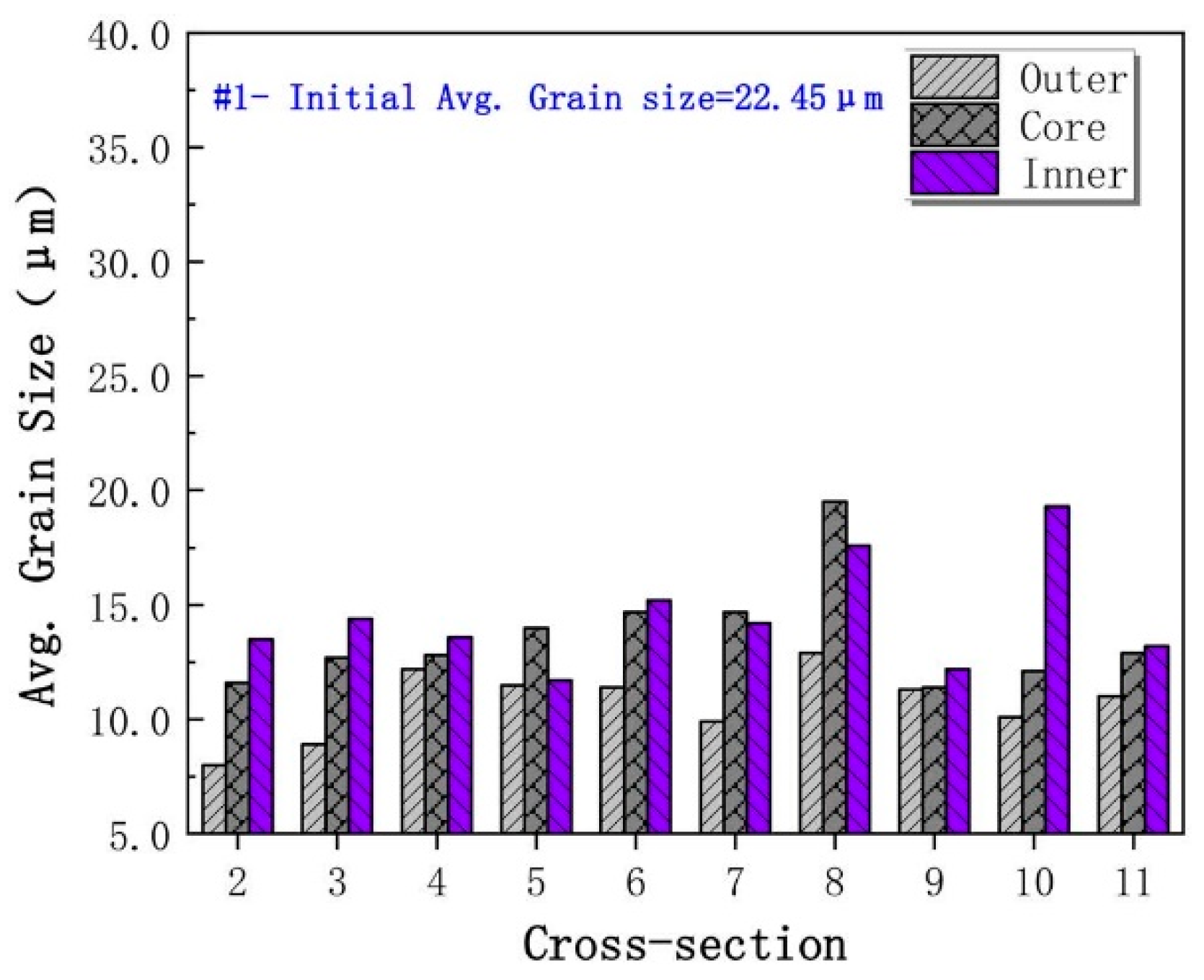
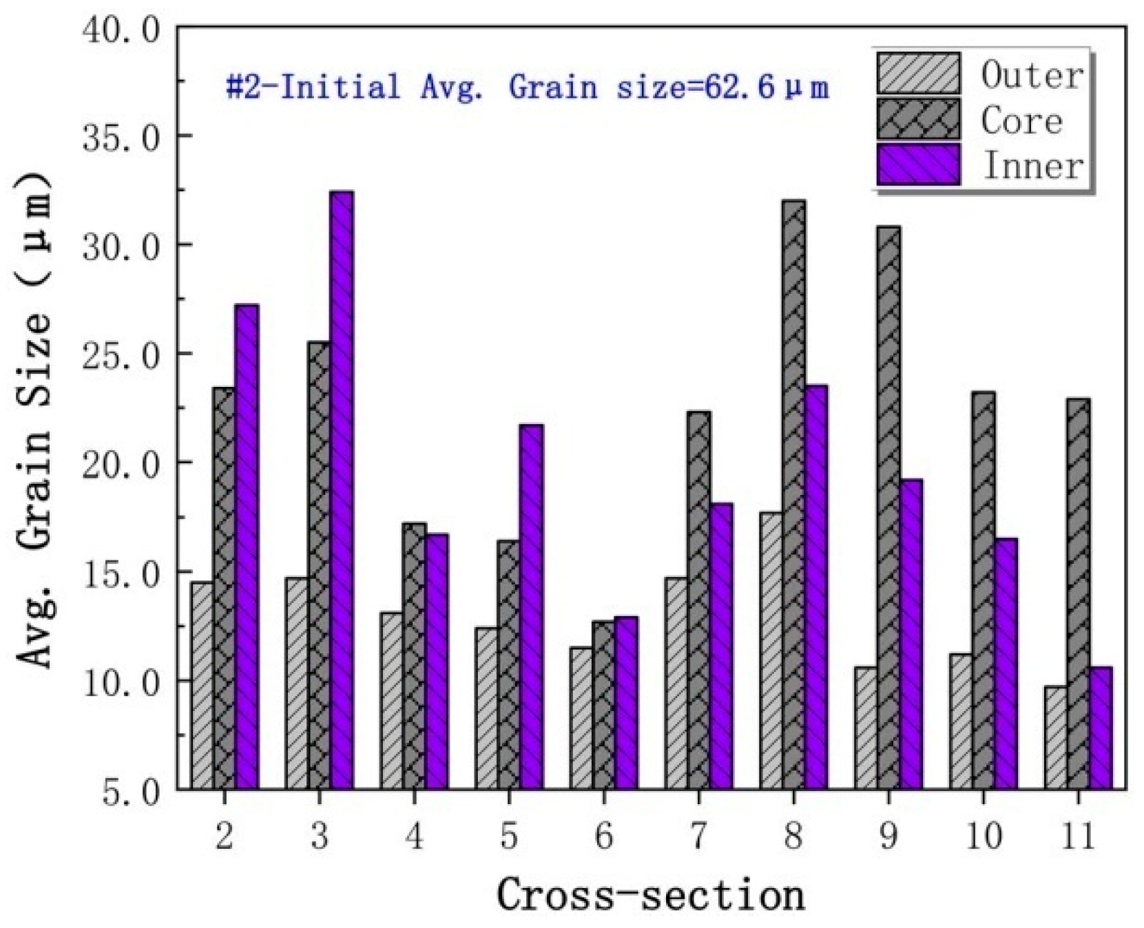
  19. Wang, J.T.; Shu, X.D.; Zhang, S. Effect of process parameters on average grain size and microscopic uniformity of the three-roll skew rolling forming of the railway hollow shaft. Metalurgija 2020, 59, 47–50. [Google Scholar]
  20. Pater, Z.; Tomczak, J.; Lis, K.; Bulzak, T.; Shu, X.D. Forming of rail car axles in a CNC skew rolling mill. Arch. Civ. Mech. Eng. 2020, 20, 1–13. [Google Scholar] [CrossRef]
  21. Pater, Z.; Patrycja, W.G. Conception of hollow axles forming by skew rolling with moving mandrel. Adv. Sci. Technol. Res. J. 2021, 15, 146–154. [Google Scholar] [CrossRef]
  22. Tomczak, J.; Pater, Z.; Bulzak, T.; Lis, K.; Tomasz, K.; Andrzej, S.; Marcin, S. Design and technological capabilities of a CNC skew rolling mill. Arch. Civ. Mech. Eng. 2021, 21, 72. [Google Scholar] [CrossRef]
  23. Shu, C.; Zhang, S.; Bidare, P.; Essa, K.; Abdel, W.A.; Shu, X.D.; Pater, Z.; Bartnicki, J. Microstructure evolution of three-roll skew-rolling formed hollow axles with uniform wall thickness. Int. J. Adv. Manuf. Technol. 2022, 121, 4069–4085. [Google Scholar] [CrossRef]
  24. Topa, A.; Kim, K.; Kim, Y. 3D numerical simulation of seamless pipe piercing process by fluid-structure interaction method. MATEC Web Conf. 2018, 203, 6016. [Google Scholar] [CrossRef]
  25. Li, Y.R.; Hui, Z.Q.; Zhang, Y.; Zheng, S.J. Hot rolling 35CrMo ultra-thick wall seamless tubes. J. Chongqing Univ. 2008, 31, 1360–1364. [Google Scholar]
  26. Romanenko, V.P.; Romantsev, B.A.; Illarionov, G.P.; Fomin, A.V.; Zimin, V.Y.; Stepanov, P.P. Billet preparation method for railcar hollow axle production. Metallurgist 2014, 58, 684–688. [Google Scholar] [CrossRef]
  27. Romanenko, V.P.; Stepanov, P.P.; Kriskovich, M. Production of hollow railroad axles by screw piercing and radial forging. Metallurgist 2018, 61, 873–877. [Google Scholar] [CrossRef]
  28. Kriskovich, S.; Romanenko, V.P.; Vavilkin, N.; Fortunatov, A. Features of the stress-strain state of screw piercing of extra-thick-walled hollow billets for mechanical engineering. ChernyeMetally 2022, 6, 55–59. [Google Scholar] [CrossRef]
  29. Wang, F.J.; Shuang, Y.H.; Zhang, G.Q. A new type of seamless steel pipe production process—Tandem skew rolling process. Steel Pipe 2014, 43, 54–58. [Google Scholar]
  30. Wang, F.J.; Shuang, Y.H. Tandem skew rolling process for compact producing seamless steel tubes. Iron Steel 2016, 51, 44–48. [Google Scholar]
  31. Pehle, H.J. Position and Future Prospects of the Seamless Steel Tube. Pipe Tube 2004, 33, 47–51. [Google Scholar]
  32. Shuang, Y.H.; Wang, F.J.; Wang, Q.H. Explorative study of tandem skew rolling process and equipment for producing seamless steel tubes. J. Mech. Eng. 2017, 53, 18–24. [Google Scholar] [CrossRef]
  33. Wang, F.J.; Shuang, Y.H.; Hu, J.H.; Wang, Q.H.; Sun, J.C. Explorative study of tandem skew rolling process for producing seamless steel tubes. J. Mater. Process. Technol. 2014, 214, 1597–1604. [Google Scholar] [CrossRef]
  34. Mao, F.L.; Shuang, Y.H.; Wang, Q.H.; Wang, F.J.; Gou, Y.J.; Zhao, C.J. Theoretical and experimental study of the tandem skew rolling process. Steel Res. Int. 2018, 89, 1800022. [Google Scholar] [CrossRef]
  35. Ding, X.F. Forming Mechanism and Experimental Research of Rotary Piercingfor Magnesium Alloy Seamless Tube. Ph.D. Thesis, Taiyuan University of Science and Technology, Taiyuan, China, 2018. [Google Scholar]
  36. Mao, F.L.; Wang, F.J.; Shuang, Y.H.; Hu, J.H.; Chen, J.X. Deformation behavior and experiments on a light alloy seamless tube via a tandem skew rolling process. Metals 2019, 10, 59. [Google Scholar] [CrossRef] [Green Version]
  37. Ye, C.Q.; Shu, X.D.; Xia, Y.X.; Wang, J.T.; Zhang, S. Mechanism of integrated forming of shape and inner hole of hollow axle. Metalurgija 2022, 61, 167–170. [Google Scholar]
Figure 1. Hollow axle of high-speed-train.
Metals 13 00145 g001
Figure 2. Forging process of hollow axle:(a) open-die forging process; (b) radial precision forging.
Metals 13 00145 g002
Figure 3. Principle of MSCWR.
Metals 13 00145 g003
Figure 5. Die of MSCWR.
Metals 13 00145 g005
Figure 6. Hollow axle rolled with MSCWR: (a) FE model; (b) forming process; (c) hollow axle [5] (Reprinted with permission from Ref. [5]. 2023, Springer Nature).
Metals 13 00145 g006
Figure 7. Model of two-stage CWR for producing rail axles by rolls with 1200 mm nominal diameter [9] (Reprinted from ref. [9]).
Metals 13 00145 g007
Figure 8. Distribution of effective strains in a rail axle produced by two-stage CWR [9] (Reprinted from ref. [9]).
Metals 13 00145 g008
Figure 9. Damage function distribution in a rail axle produced by two-stage CWR [9] (Reprinted from ref. [9]).
Metals 13 00145 g009
Figure 10. Three-roll cross-wedge rolling [10] (Reprinted from ref. [10]).
Metals 13 00145 g010
Figure 11. Numerically simulated distribution of effective strain in cross-rolled rail axles [10] (Reprinted from ref. [10]).
Metals 13 00145 g011
Figure 12. Numerically simulated distribution of damage function in cross-rolled rail axles [10] (Reprinted from ref. [10]).
Metals 13 00145 g012
Figure 13. Design of the skew rolling process with three tapered rolls [12] (Reprinted from ref. [12]).
Metals 13 00145 g013
Figure 14. Velocity vector analysis diagram of deformation zone of three-roll skew rolling axle [13,14]. (Reprinted from ref. [13,14]).
Metals 13 00145 g014
Figure 15. Distribution of temperature field in the three-roll skew rolling rail axle [16] (Reprinted from ref. [16]).
Metals 13 00145 g015
Figure 16. Distribution of strain intensity in the three-roll skew rolling rail axle [16] (Reprinted from ref. [16]).
Metals 13 00145 g016
Figure 17. Rail axles produced in 1:5 scale after machining allowance removal and shot peening [20] (Reprinted from ref. [20]).
Metals 13 00145 g017
Figure 18. Locations of the cross-section in the rolled piece for microstructure observation samples [23] (Reprinted from ref. [23]).
Metals 13 00145 g018
Figure 19. Average grain size at different cross-sections in No. 1 rolled piece [23] (Reprinted from ref. [23]).
Metals 13 00145 g019
Figure 20. Average grain size at different cross-sections in No. 2 rolled piece [23] (Reprinted from ref. [23]).
Metals 13 00145 g020
Figure 21. Schematic diagram of the rotary piercing process: (a) front view; (b) top view [24] (Reprinted from ref. [24]).
Metals 13 00145 g021
Figure 22. Forming inner hole of hollow axle by rotary piercing: (a) rolling mill; (b) billet piercing process; (c) steel pipe [26] (Reprinted with permission from Ref. [26]. 2023, Springer Nature).
Metals 13 00145 g022
Figure 23. Hollow axle blank [27] (Reprinted with permission from Ref. [27]. 2023, Springer Nature).
Metals 13 00145 g023
Figure 24. Process principle of tandem skew rolling [36] (Reprinted from ref. [36]).
Metals 13 00145 g024
Figure 25. Tandem skew rolling mill [36] (Reprinted from ref. [36]).
Metals 13 00145 g025
Figure 26. Finished seamless steel pipe prepared by tandem skew rolling [36] (Reprinted from ref. [36]).
Metals 13 00145 g026
Figure 27. Tandem flexible skew rolling [37] (Reprinted from ref. [37]).
Metals 13 00145 g027
Figure 28. Design of the process for producing hollow axle [37] (Reprinted from ref. [37]).
Metals 13 00145 g028
Figure 29. Change of force parameters of each part during forming [37] (Reprinted from ref. [37]).
Metals 13 00145 g029
Figure 30. Distribution of effective strain in hollow axle [37] (Reprinted from ref. [37]).
Metals 13 00145 g030
Figure 31. Distribution of temperature in hollow axle [37] (Reprinted from ref. [37]).
Metals 13 00145 g031
Table 1. Comparison between MSCWR process and forging process.
AdvantagesDisadvantages
High efficiencyLarger die
High material utilizationLow roundness
Table 2. Comparison between TRSR process and forging process.
AdvantagesDisadvantages
Low energy consumptionPoor workpiece surface quality
Universal die
Small equipment size
Low material utilization
Table 3. Comparison between TFSR process and forging process.
AdvantagesDisadvantages
High efficiencyPoor workpiece surface quality
High material utilization
Low energy consumption
Complex equipment structure
Disclaimer/Publisher’s Note: The statements, opinions and data contained in all publications are solely those of the individual author(s) and contributor(s) and not of MDPI and/or the editor(s). MDPI and/or the editor(s) disclaim responsibility for any injury to people or property resulting from any ideas, methods, instructions or products referred to in the content.

