Article

Friction Stir Lap Welding of Inconel 625 and a High Strength Steel

by
Elisangela Pelizzari Bossle
1,
Buchibabu Vicharapu
2,
Guilherme Vieira Braga Lemos
3,*,
Cleber Rodrigo de Lima Lessa
4,
Luciano Bergmann
5,
Jorge Fernandez dos Santos
6,
Thomas Gabriel Rosauro Clarke
1 and
Amitava De
7
1
Laboratório de Metalurgia Física (LAMEF), Programa de Pós Graduacão em Engenharia de Minas, Metalúrgica e de Materiais (PPGE3M), Universidade Federal do Rio Grande do Sul (UFRGS), Porto Alegre 91501-970, RS, Brazil
2
Indian Institute of Technology Palakkad, Palakkad 678623, India
3
Engenharia Mecânica, Campus Cachoeira do Sul, Universidade Federal de Santa Maria (UFSM), Cachoeira do Sul 96503-205, RS, Brazil
4
Programa de Pós-Graduação em Tecnologia e Engenharia de Materiais (PPGTEM), Instituto Federal do Rio Grande do Sul (IFRS), Caxias do Sul 95043-700, RS, Brazil
5
Solid State Materials Processing (WMP), Institute of Materials Mechanics, Helmholtz-Zentrum Hereon, 21502 Geesthacht, Germany
6
Energy and Environment Directorate, Pacific Northwest National Laboratory, Richland, WA 99354, USA
7
Indian Institute of Technology, Mumbai 400076, India
*
Author to whom correspondence should be addressed.
Metals 2023, 13(1), 146; https://doi.org/10.3390/met13010146
Submission received: 3 December 2022 / Revised: 2 January 2023 / Accepted: 8 January 2023 / Published: 10 January 2023
(This article belongs to the Special Issue New Advances in Dissimilar Material Joining)

Abstract

:
The joining of dissimilar hard metals such as high-strength steel and nickel-based alloy is required for shipbuilding and offshore applications to enhance the strength, fracture toughness, and corrosion resistance of the exposed parts. However, the joining of these dissimilar alloys has remained a major challenge due to the limited solubility of Fe and Ni in each other, which commonly results in the formation of brittle intermetallic compounds. We present here a novel investigation on the joining of overlapped nickel-based alloy 625 and marine-grade GL E36 steel plates by friction stir lap welding (FSLW). The interface microstructure and its influence on joint strength are rigorously tested. The main bonding mechanism is found to be the mechanical mixing of Fe and Ni along the interface. The interface thermal cycles are computed by a three-dimensional numerical heat transfer model and their effects on the microstructure are examined. Multiple micro tensile specimens are extracted from the stir zone to examine the through-thickness variation in the stir zone properties. The welded joint is characterized further by evaluating the interface microhardness distribution, lap-shear strength, and surface residual stresses.

1. Introduction

The lapping of nickel-based alloy plates on thick, high-strength steel plates is a potential route to improve the strength and serviceability of the steel plates for marine and offshore applications [1,2]. However, the fusion welding of nickel-based alloys might lead to severe degradation of their material properties and increased susceptibility to both hot cracking and reheat cracking, which also depends on the process conditions [3,4,5]. In contrast to fusion welding, friction stir lap welding (FSLW) involves the joining of alloys in a solid-state manner, which can mitigate the challenges due to melting and solidification [6]. Although FSLW of stainless steel [7], copper [8], and aluminium alloy [9,10] plates on high-strength steel substrates have been reported in recent times, similar studies on FSLW of nickel-based alloy on steel substrate have just begun [6,11].
Li et al. [12] used FSLW to fabricate aluminized titanium plates to improve their oxidation resistance. Anand and Sridhar [13] presented a review of the influence of tool rotational speed, welding speed, and tool geometry on the joint structure and properties for FSW of similar and dissimilar aluminium alloys. The effect of tool offset [14] and tool probe eccentricity [15] on the welded joint structure and property was also examined for FSW of Al-alloys. FSLW was used to produce Al-Cu bimetallic tubes [16] and plates [17] to enhance their shear strength. Kimura et al. [18] joined a nickel-based alloy plate with a heat-resistant steel substrate using continuous drive friction welding (FW) and reported the formation of a thick mechanically mixed zone across the interface. A similar intermixed zone along the joint interface was also reported for FW of Inconel 718 with S45C medium carbon steel [19] and of Fe-Ni and Fe-Cu with Ti-Cu alloy [20]. Friction stir welding (FSW) of steel and Ti-alloy plates with Al-alloy substrates also led to the formation of interface intermixed zones [21,22]. The presence of a mechanically mixed zone at the joint interface has been shown to provide good mechanical properties and joint strength in FSLW of dissimilar materials such as aluminum alloys and steel [18], and aluminum and titanium alloys [23]. The influence of the thermal cycles on the evolution of the interface intermixed zone was investigated for FSLW [24], gas-metal arc (GMA) brazing [25], and gas tungsten arc (GTA)-assisted FSW [26] of dissimilar alloys. The aforementioned literature shows an increasing interest in the solid-state joining of dissimilar alloys and FSLW of Ni-based alloy with steels has been of continuing importance.
A detailed investigation on FSLW of a nickel-based alloy on a marine-grade steel substrate is therefore considered in this work. The evolution of the microstructure in the interface intermixed region is examined thoroughly. The computed thermal cycles from a three-dimensional heat transfer analysis are used for a quantitative understanding of Fe and Ni diffusion in the intermixed region. The tensile mechanical properties of the joint and of the stir zone are evaluated using lap-shear and micro-tensile samples, respectively. The influence of the microstructure on the joint properties is reported.

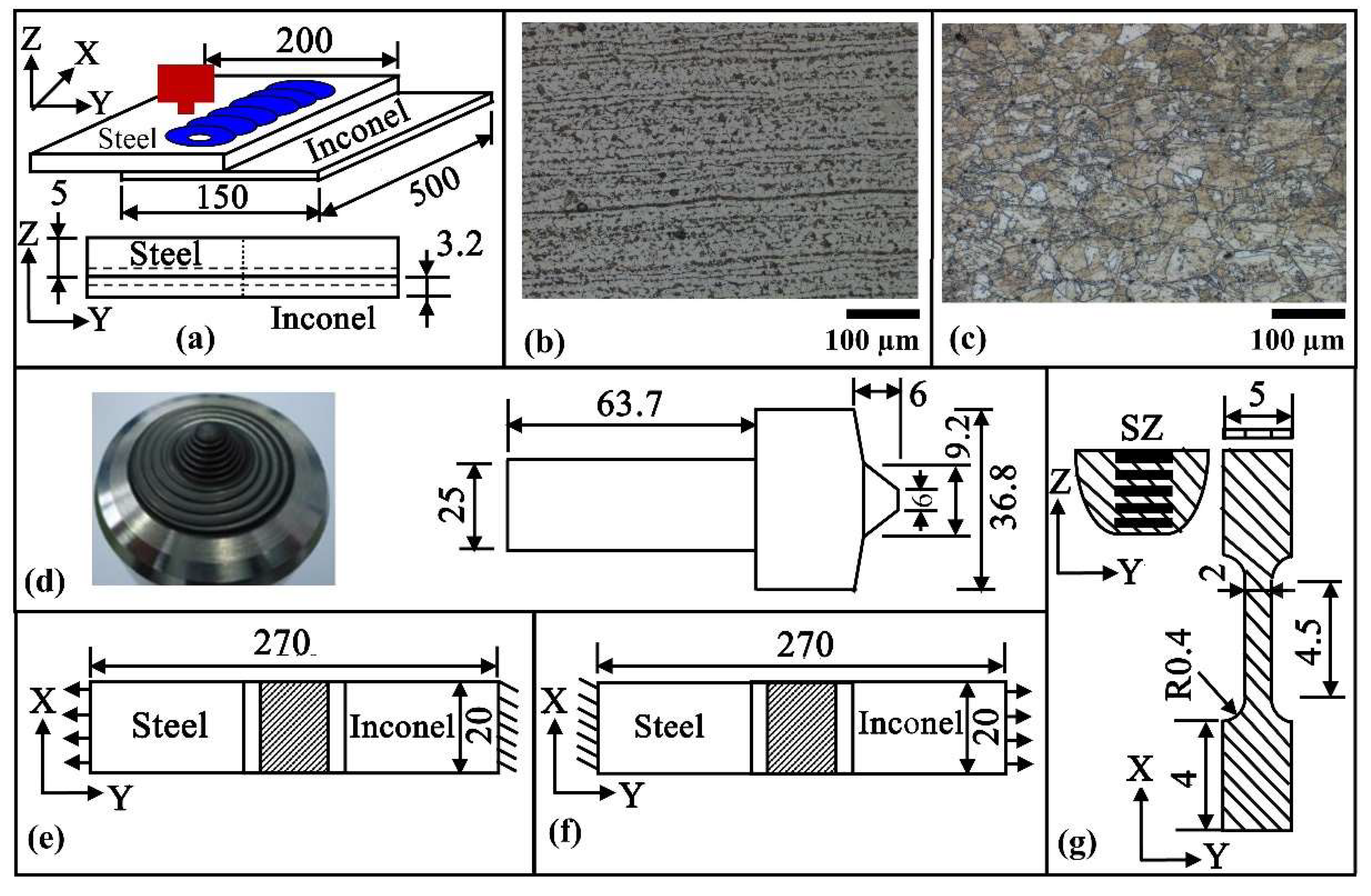
2. Materials and Methods

A 3 mm thick Inconel 625 plate was friction stir-lap welded onto a marine-grade GL E36 steel substrate using FSLW. Table 1 presents the chemical composition of the Inconel 625 and GL E36 steel materials. Figure 1a shows the lap joint configuration and the dimensions of both the steel and Inconel 625 plates. Figure 1b,c show the microstructures of the steel and Inconel 625 plates, respectively, in the as-received condition. The steel plate (Figure 1b) exhibits ferrite and pearlite phases aligned in the rolling direction. The Inconel 625 plate (Figure 1c) shows an austenite phase with MC carbonitrides in the nickel matrix, and M6C and M23C6 carbides along some grain boundaries [27]. FSLW was carried out at a constant tool rotational speed of 500 rpm and two different tool travel speeds of 1 mm/s and 3 mm/s. Figure 1d shows a three-dimensional view of the FSLW tool and its dimensions on a two-dimensional section. The tool conforms to a Q70 type of pcBN and is manufactured by MegaStir©. The tool was set at a tilt angle of 1° with its normal to the steel surface [27,28,29,30]. The tool was inserted through the steel and introduced to the Inconel 625 to minimize the interaction between the tool and the nickel-based alloy to avoid wear and damage to the tool [31]. The tool probe penetrates 1 mm into the Inconel 625 plate. Argon gas was used for shielding from the steel top surface. The thermal cycles were measured using K-type thermocouples at a depth of around 3.5 mm from the steel surface and 15 mm away in the transverse direction from the tool shoulder periphery.
The specimens for microscopy analysis were considered from the mid-length of the actual weld seam. The welded specimens were transversely cut using a diamond-plated blade and ground and polished for microstructure evaluation. The GL E36 steel and Inconel 625 were etched individually with 3% Nital and Adler solutions, respectively. A scanning electron microscope (SEM) equipped with an energy dispersive spectroscope (EDS) was used to examine the diffusion of Fe and Ni through the interface and for fractography analysis. The residual stress was measured using X-ray diffraction (XRD) on both the GL E36 steel and Inconel 625 sides using a GE-Seifert-Charon-M X-ray diffractometer (research edition) with Bragg–Brentano geometry and an X-ray tube with Cr–Kα radiation [27]. A diffracted beam was used from a collimator with a 2 mm primary aperture and a 20° GE-Meteor-1D linear detector. The evaluation of the residual stresses considered the sin2ψ method [27]. The microhardness distributions were measured with a load of 500 g and at a regular gap of 0.3 mm along the dashed lines in the Y-direction as shown in Figure 1a. Similarly, the hardness measurements were also done along the dotted line in the Z-direction (through-thickness) at a regular gap of 0.15 mm (Figure 1a).
Figure 1e,f show the transverse welded specimens for the evaluation of the joint tensile strength. Six lap-shear specimens were tested for each process condition with the steel plate being pulled for three cases, as shown in Figure 1e, and the Inconel 625 plate being pulled for the other three samples, as shown in Figure 1f. The separate engagement of the steel and Inconel 625 plates during the lap-shear tensile testing was conducted to evaluate the effect of stir zone asymmetry on the final weld joint strength. Figure 1g shows the longitudinal micro-tensile testing specimen and its dimensions, which are extracted from different heights through the stir zone. The micro-tensile specimens conform to a thickness of 0.5 mm. In total, eight micro-tensile specimens were extracted through the 8.2 mm thick stir zone (SZ), as shown in Figure 1g, for each process condition to examine the local variations of the joint quality through the stir zone (SZ) thickness.

3. Theoretical Formulation

A steady-state three-dimensional heat conduction analysis has been carried out considering the following governing equation:
x ( k T x ) + y ( k T y ) + z ( k T z ) + Q ˙ = ρ C P v T x
where v is the tool travel speed, ρ, k, and Cp refer to the density, thermal conductivity, and specific heat of the workpiece materials, respectively, T is the temperature variable, and, x, y and z are spatial variables. Figure 1a shows the solution domain considered for the analysis. The FSLW process was simulated considering the Inconel 625 plate lapped onto the steel plate from the bottom and an introduction of the tool probe from the top through the steel plate until a depth of 0.5 mm into the Inconel 625 plate. The term on the right-hand side of Equation (1) accounts for the spatial temperature gradient that evolves due to the relative velocity between the workpiece and the tool. The rate of heat generation q along the tool–workpiece interface has been computed as:
q = η h [ η m ( 1 δ ) τ y + δ μ f P N ] ( ω r ) ( A i / V i )
where ηh and ηm are the fraction of total heat transferred to the workpiece materials and the fractional mechanical work due to sticking friction converted to heat, respectively, r is the radial distance of a point i from the tool axis, and, PN, ω, and τy are the axial pressure, the angular speed of the tool, and the shear yield stress of workpiece materials, respectively. The terms δ and µf in Equation (2) provide a measure of the local variations of fractional sliding and the co-efficient of friction along the tool–workpiece interface and are calculated empirically as [31,32]:
δ = 0.026 + 0.50 exp ( r ω / 1.87 )
μ f = 0.51 exp ( δ r ω )
The term Q ˙ in Equation (1) was used to provide the heat generation per unit volume along the tool probe and workpiece interface and estimated as [31,32]
Q ˙ = q ( A i / V i )
where the term (Ai/Vi) refers to the ratio of the contact area to the shear volume of a small element, which encloses the point i, along the tool–workpiece interface [31,32].
The steel and Inconel 625 plate surfaces, open to the atmosphere, were assumed to experience heat loss due to natural convection and a temperature-dependent film heat transfer co-efficient h0(T − T0)0.25, where h0 = 5 W/m2K0.25, was applied [31,32]. The overlapped plate assembly was clamped on a backup plate and to account for this, a constant film heat transfer coefficient (h) of 10 W/m2 K was applied along the bottom surface of the Inconel 625 plate [31,32].
The numerical heat conduction model for FSLW was implemented using the commercial finite element software, ABAQUS© 2020. The solution domain was discretized using a linear three-dimensional eight-node iso-parametric brick element DCC3D8 with temperature as the nodal degree of freedom [24,31]. The solution domain was meshed with a minimum element size of 0.2 mm for the tool–workpiece interface region to a maximum element size of 2 mm for the regions far from the interface. The user subroutine DFLUX in ABAQUS was used for the calculation of both the surface heat flux q and the volumetric heat input Q ˙ terms [31]. Likewise, the user subroutine UFILM in ABAQUS was utilized to compute the convective heat loss along the steel and Inconel 625 plate surfaces [31] The relative velocity between the overlapped plates and the tool was accounted for by using a user subroutine UMASFL [31]. Samples of these three user subroutines, as used in the present work, are presented in Appendix A. The temperature-dependent thermo-physical properties of Inconel 625 and GL E36 steel are considered from references [31,33] and provided in Table 2. A single layer of discrete elements of 0.2 mm height was used to consider the interface between the steel and Inconel 625 plates and the material properties along this interface region were an average of those for Inconel 625 and steel.

4. Results and Discussion

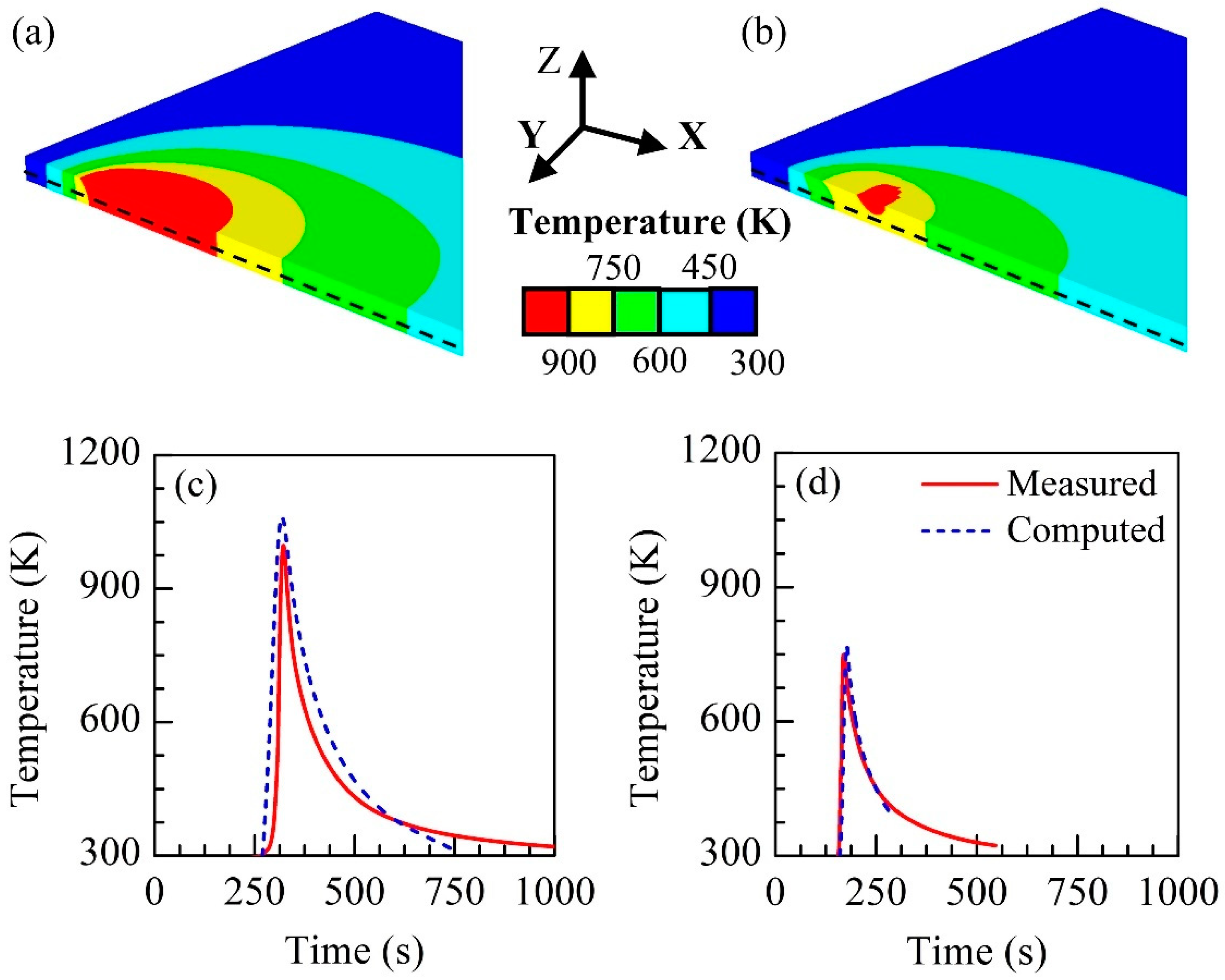
4.1. Temperature Distribution and Thermal Cycles

Figure 2a,b shows the computed temperature field for a constant tool rotational speed of 500 rpm and two tool travel speeds of 1 mm/s and 3 mm/s. The computed peak temperature at the joint interface is around 1249 K and 896 K for the tool travel speeds of 1 mm/s and 3 mm/s, respectively. The reduced peak temperature at higher tool travel speed is attributed to the decrease in the rate of heat generation per unit length of weld. Figure 2c,d exhibits a fair match between the numerically computed and corresponding experimentally measured thermal cycles at the two different tool travel speeds. Although the formation of the intermetallic compound FeNi3 appears to be likely between the temperature range of around 473 K to 790 K, such a reaction requires a long-time duration [34,35]. A solid solution of FCC nickel and the austenite phase is expected above 1000 K [34,35]. Although a strong interdiffusion between the austenite phase and nickel is likely above 790 K due to their identical FCC structure, the formation of FeNi3 at the low temperature range from 473 K to 790 K also requires a long duration, Figure 2c shows a time duration of around 115 s between the temperature range 473 K to 790 K, which is deemed inadequate for the formation of the intermetallic compound FeNi3. Figure 2d also shows a very small time duration between the temperature range 473 K to 790 K.

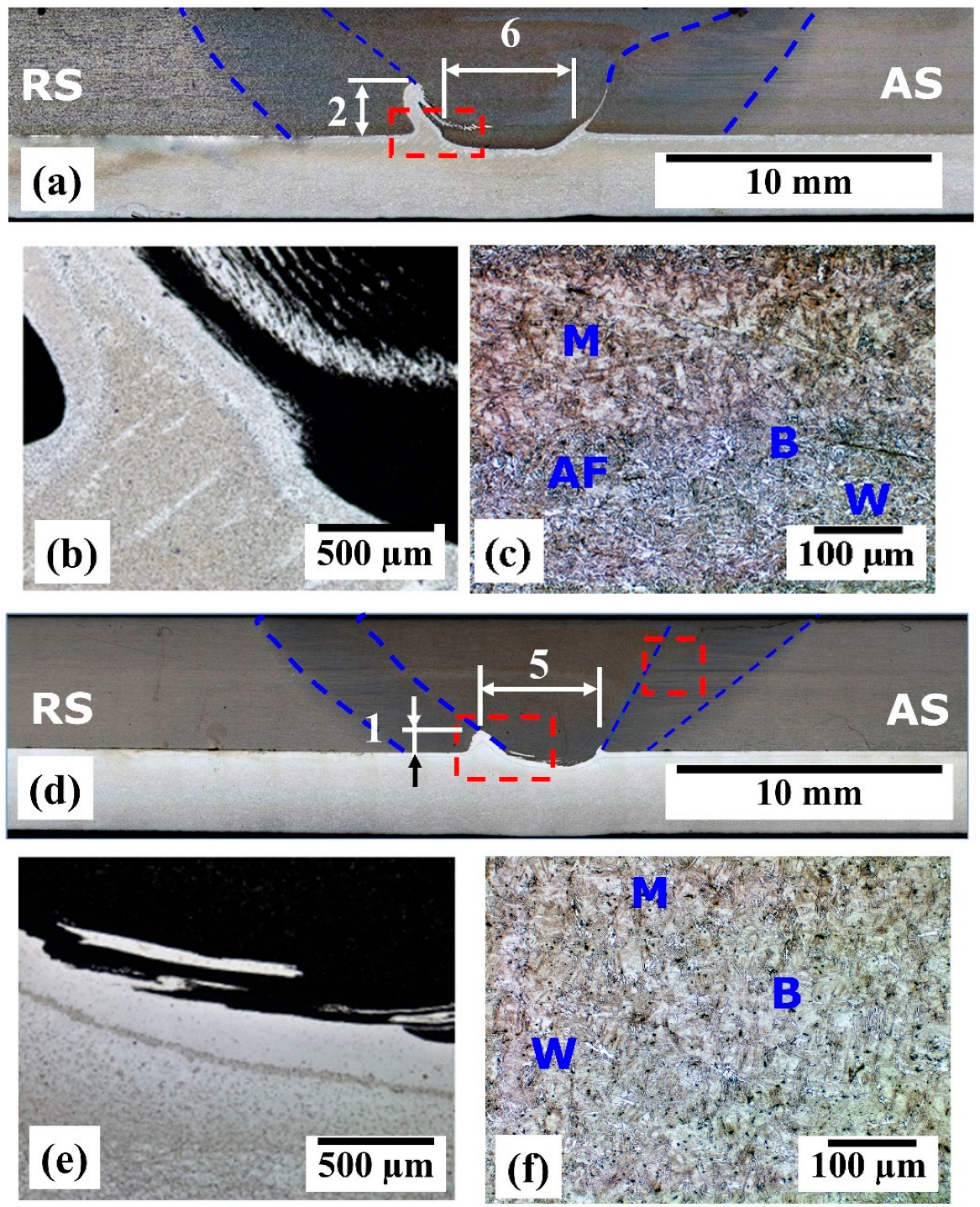
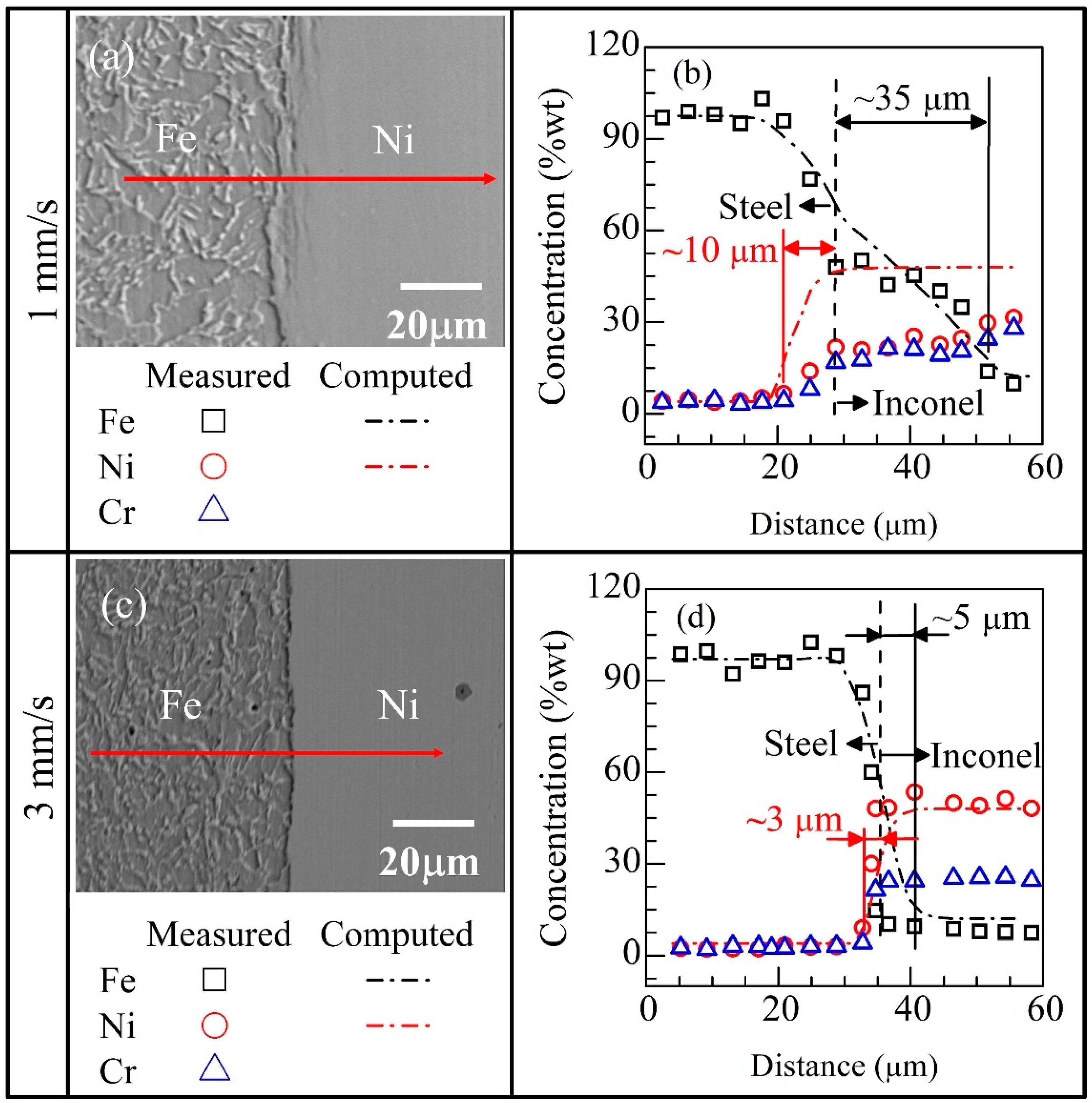
4.2. Macro and Microstructures of the Processed Regions

Figure 3a–f shows the macrographs of the joint cross-sections for two different tool travel speeds, and the corresponding zoomed views of a joint interface and a stir zone. The formation of a typical hook is observed for both joints as shown in Figure 3a,d. The hook height and the bonding length near the interface are found around 2 mm and 1 mm, and 6 mm and 5 mm, respectively, for the tool travel speeds of 1 mm/s and 3 mm/s. The formation of the hook is attributed to the severe plastic deformation of Inconel 625, particularly beneath the tool probe. The “hook formation” is more prominent in Figure 3a than in Figure 3d. The high softening of the Inconel 625 at a higher interface temperature (~1249 K) due to a lower tool travel speed resulted in high hook height Figure 3a. In contrast, the peak temperature was smaller at the higher tool travel speed resulting in relatively colder and harder material and no prominent hook formation has been noted in Figure 3d.
Figure 3b,e shows the zoomed views of the joint interface location for the two tool travel speeds. The dark and bright regions in Figure 3b,e correspond to steel and Inconel 625, respectively, and their appearances are due to the Adler solution, which reveals only the Inconel 625 microstructure. The formation of the alternate layers of GL E36 steel and Inconel 625 in Figure 3b arises from intermixing, which occurs due to the shearing of Inconel 625 beneath the tool probe. Similar shear layers and intermixed zone near the center of the consumable steel plug was also observed in friction hydro-pillar processing (FHPP) [6]. The intermixing of GL E36 steel and Inconel 625 is nearly absent in Figure 3e, which is attributed to inadequate thermal softening and plastic flow of materials at a higher tool travel speed. For example, the computed peak temperatures of Inconel 625 are around 1249 K and 896 K for the tool travel speeds of 1 mm/s and 3 mm/s, respectively. Corresponding to these peak temperatures, the shear strengths of Inconel 625 are around 223 MPa and 126 MPa, respectively. The greater rate of thermal softening and plastic deformation of Inconel 625 at the lower tool travel speed of 1 mm/s has therefore promoted a prominent hook formation and intermixing between GL E36 steel and Inconel 625. The bright layer in Figure 3b,e refers to the diffused Fe and Cr from steel in Ni-matrix.
Figure 3c,f show the microstructures in the stir zone near the top surface of the welded GL E36 steel plate at the tool travel speeds of 1 mm/s and 3 mm/s, respectively. As shown in Figure 3c, the steel microstructure exhibits a predominance of Bainite (B) and Widmanstätten ferrite (W), with needle-shaped acicular ferrite (AF). Furthermore, the bright-like structure is identified as M in Figure 3c. In contrast, no AF could be traced in the stir zone (Figure 3f). This has been attributed to the high cooling rates and low transformation temperatures; meaning that intragranular nucleation sites are unable to induce the AF transformation, and as a result, the main microstructure is B. In addition, less time would be available for stirring the material at the higher travel speed (Figure 3f, 3 mm/s), which has facilitated the formation of the phase that does not involve diffusion (Martensite (M)) rather than those that take a longer time to grow; so, it has more M than that in Figure 3c. The stir zone in the welded GL E36 steel plate confirmed the AF, M, B, and W phases under similar process conditions as also reported by Cunha et al. [30].
Figure 4 shows the SEM images (Figure 4a,c) and the corresponding EDS line scans (Figure 4b,d) of the joint interface at two different tool travel speeds. A comparison of Figure 4a,c show an uneven interface profile at the lower tool travel speed, which is attributed to the greater plastic flow of GL E36 steel. A common boundary that finds a minimum of 40% to 60% of the parent elements of the respective workpiece materials is considered a tentative original interface for this study. The SEM micrographs and EDS line scan data, which are presented in Figure 4, are utilized for this purpose. The EDS measurements show Fe diffusing in Inconel 625 up to a depth of around 25 µm and, Ni and Cr diffusing up to a depth of around 10 µm in steel at a tool travel speed of 1 mm/s (Figure 4b). The higher diffusion depth of Fe in Inconel 625 is attributed to the FCC structure of both Fe and Ni matrices at a high interface temperature and relatively longer diffusion time. In contrast, the diffusion of Fe in Ni and Ni in the Fe matrix is found to decrease significantly to 5 µm and 3 µm, respectively, at the higher tool travel speed of 3 mm/s, which is attributed to the lower peak temperature (896 K) along the interface (Figure 4d).
The measured Fe and Ni diffusion profiles shown in Figure 4b,d can be expressed well by the standard empirical relation DV = D × exp(−Q/RT), where D, Q, R, and T refer to the diffusion coefficient, activation energy, universal gas constant, and temperature variable, respectively [22,23,25,34]. The values of the diffusion constant D as 10.6 and 2.5 respectively for the diffusion of Fe in the Ni matrix and Ni in the Fe matrix are found to represent the measured diffusion profiles for both the tool travel speeds. The SEM images in Figure 4a,c show the joint interface with little or no contrast difference, which is presumed to indicate an absence of intermetallic compounds. This is attributed to inadequate time for elemental interdiffusion and lower peak temperature. The absence of FeNi3 compound for FSW of Inconel 625 and steel was also reported by Rodrigues and Ramirez [35], although they noted a thin layer of NbC carbide along the joint interface. A further examination for IMCs along the joint interface involving expensive TEM microscopy analysis is, therefore, not attempted as a part of this study. The diffusion of Cr in the Fe matrix is not examined further considering the unlikely formation of any intermetallic compounds [36].

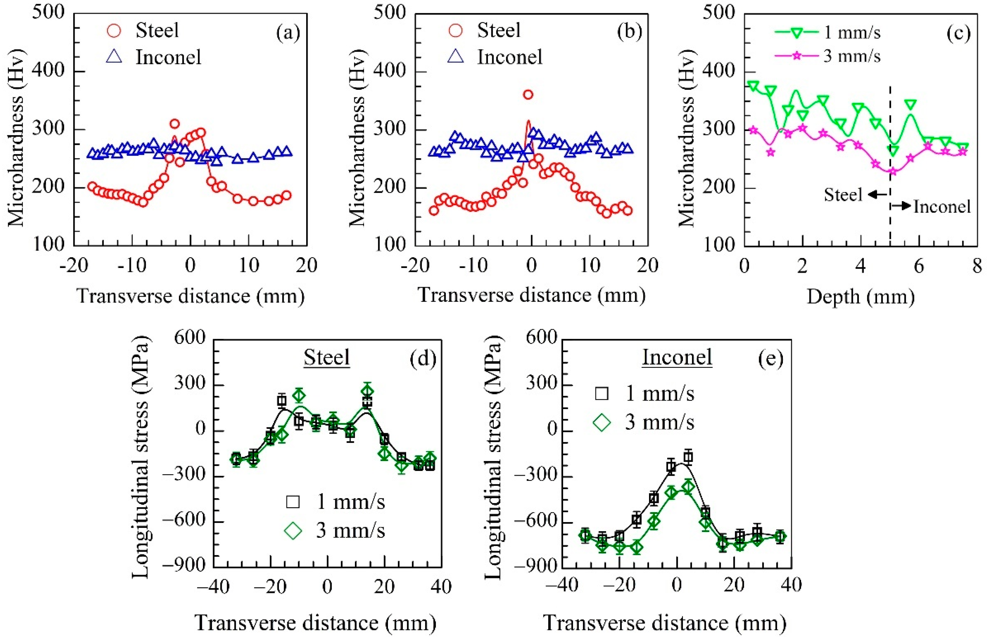
4.3. Hardness and Surface Residual Stresses

Figure 5a,b show the measured hardness distribution on the GL E36 steel and Inconel 625 for the tool travel speeds of 1 mm/s and 3 mm/s, respectively. The hardness values within the stir zone (~3 mm from the weld center) on either side are found to vary between 375 Hv to 425 Hv, which is attributed to the martensite and bainite phases as exhibited in Figure 3c. The sharp fall in hardness is apparent between ~3 mm to 8 mm from the weld center on both sides of the joint in Figure 5a, which is depicted as the thermo-mechanically affected zone (TMAZ). The drop in the hardness in the TMAZ is attributed to the lower peak temperature and cooling rates, which are ineffective to form hard phases. The hardness value beyond ~8 mm from the weld center is around 195 ± 5 Hv, which is close to the hardness of the GL E36 steel before FSLW (unprocessed steel presenting the microstructure composed of ferrite and pearlite). The hardness of Inconel 625 remains nearly the same at around 270 ± 10 Hv.
For the tool travel speed of 3 mm/s, Figure 5b shows a peak high hardness (~370 Hv) near the weld center that drops in the TMAZ region. The high hardness near the weld center can be attributed to the formation of harder phases, as indicated in Figure 3f. A similar harness profile was also reported by Cunha et al. [29] and Vicharapu et al. [33] for friction-based welding of GL E36 steel. Figure 5c shows a comparison of the measured hardness distribution along the weld center through the plate thickness for two tool travel speeds. The consistently lower hardness at the higher tool travel speed is attributed to the formation of relatively softer phases near the joint interface.
Figure 5d,e present the measured longitudinal residual stresses at the top surface of steel and the bottom surface of Inconel 625 for two travel speeds. The as-received GL E36 steel and Inconel 625 surfaces exhibited compressive residual stresses of around −200 MPa and −800 MPa, respectively. Figure 5d shows a typical ‘M’-shaped tensile stress distribution for both the tool travel speeds. The measured residual stresses on the Inconel 625 surface in Figure 5d show a bell-shaped profile with very little tensile stress beneath the joint interface at the lower tool travel speed. Overall, Figure 5c,d show the evolution of very little or no tensile residual stresses on the Inconel 625 surface and only a small peak tensile residual stress on the GL E36 steel surface due to FSLW. A further investigation of the residual stresses at the joint interface is, therefore, not carried out in the present study.

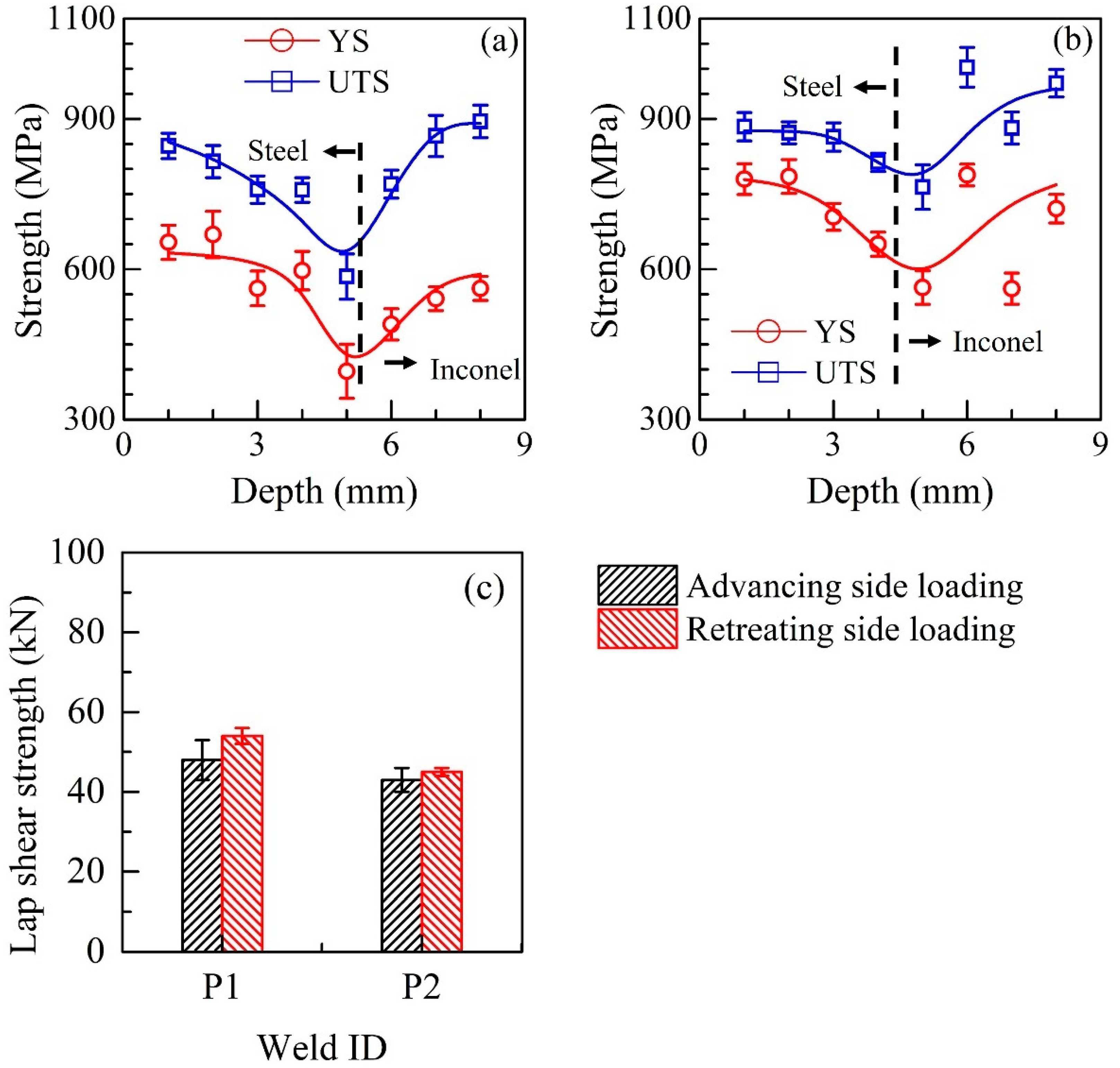
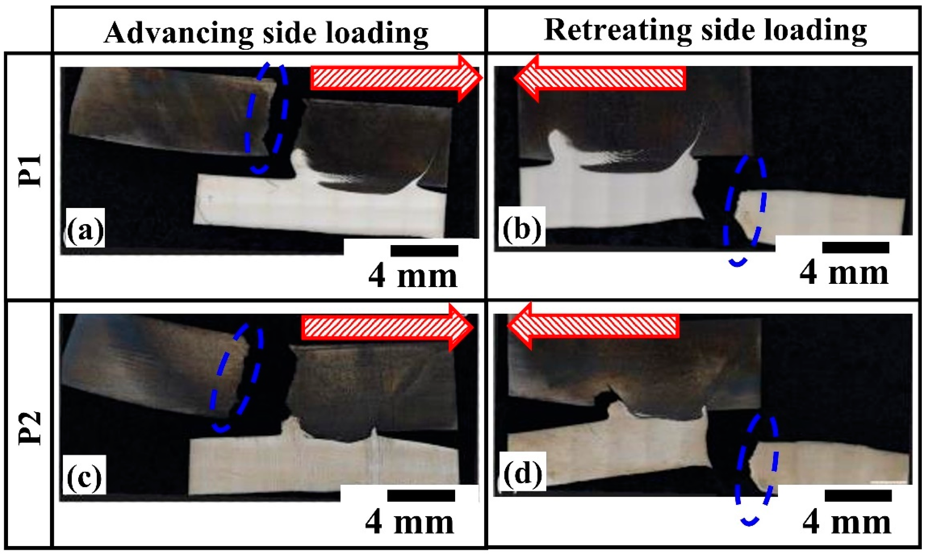
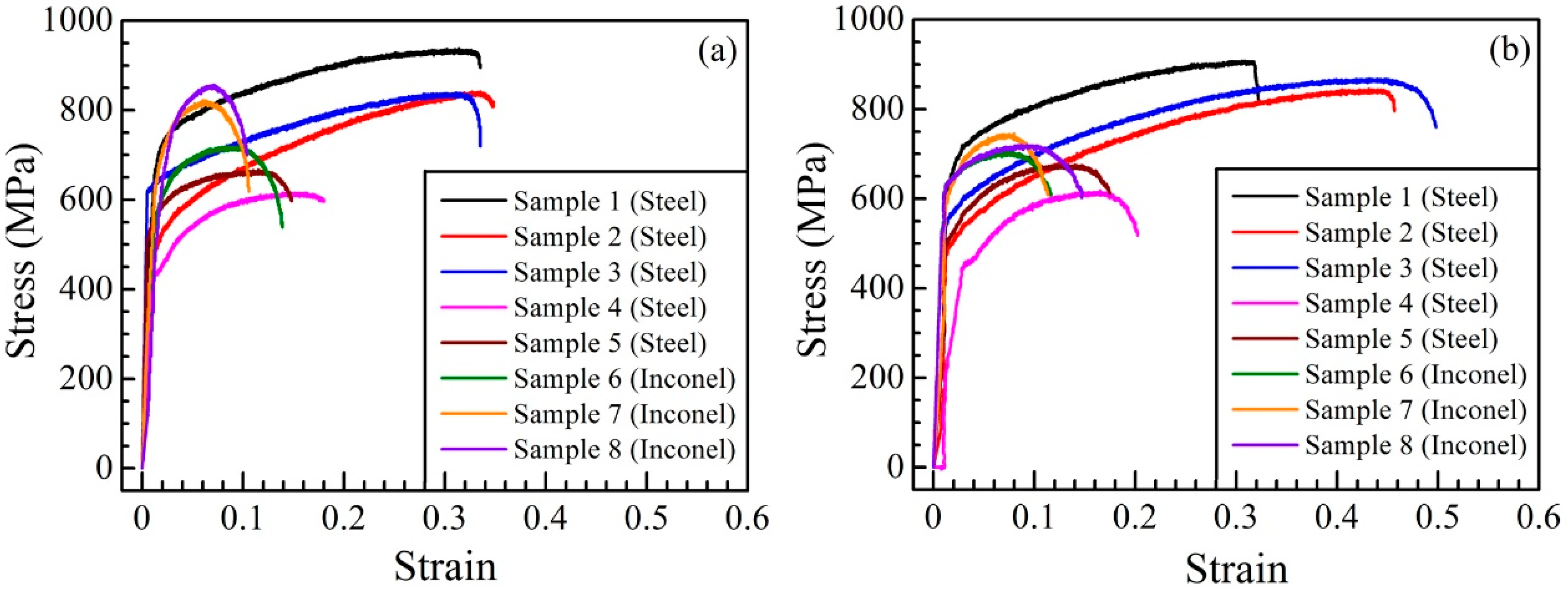
4.4. Tensile and Lap Shear Properties of the Joints

Figure 6a,b show the yield strengths (YS) and ultimate tensile strengths (UTS) at different depths through the stir zone, which were measured using micro tensile samples. Such results are rarely reported in the context of FSLW. The measured stress-strain curves for the micro-tensile specimens through the steel-Inconel thickness, as shown in Figure 1g, for each welding condition are presented in Appendix B. The measured strengths decrease gently through the stir zone in the steel up to the joint interface followed by an increase in the Inconel 625. The decrease in strength is slightly higher at the higher tool travel speed of 3 mm/s, which is attributed to the formation of the softer phases as discussed in the previous sections. The mechanically mixed zone at the joint interface showed a lower strength compared to that of both the base materials in Figure 6a,b. This is due to the local variation in chemical composition, and inadequate material mixing at the joint interface. A thin layer of brittle compounds may also have deteriorated the joint properties [35]. A subsequent increase in the measured strength on the Inconel 625 side is attributed to there being very little stirring of the bulk Inconel 625 during the welding process. The nature of the variation in YS and UTS through the stir zone thickness in Figure 6a,b corroborates well with the through-thickness hardness variations shown in Figure 5c.
The hook shape near the joint interface is asymmetric about the weld center (ref. Figure 2a,d) which can affect the load-bearing capacity of the joint based on the application of the loading in actual applications. The lap shear tests are therefore conducted considering the loading on both the advancing and retreating side and the results are shown in Figure 6c. The lap shear strengths of the joints, which are loaded on the retreating side, are found to be slightly higher at both tool travel speeds. Figure 7 shows the fractured lap shear specimens for both tool travel speeds. A comparison of Figure 7a–d shows that the samples loaded on the retreating side have always failed through the Inconel 625, which is stronger. In contrast, the samples loaded on the advancing side have failed through the steel, which is attributed to a possible crack opening in the vicinity of the hook and its propagation through the softer stir zone in steel.
The nature of the fracture of the lap shear specimens is examined further by a rigorous fractography analysis, presented in Figure 8. The figure shows the fractographies for two different process conditions. The denser dimples in Figure 8a,c represent a ductile failure in the steel. In contrast, the less-populated dimples with more depth in Figure 8b,d exhibit the ductile failure of the Ni-matrix, enriched with carbides.
In summary, Inconel 625 is joined with a marine-grade GL E36 steel substrate by FSLW at a constant tool rotational speed and two different tool travel speeds. The computed peak temperatures at the joint interface are found to be around 1249 K and 896 K for tool travel speeds of 1 mm/s and 3 mm/s, respectively. The joint interface shows the formation of a typical hook from Inconel 625 and its size varies with tool travel speed. A detailed microstructural analysis revealed no intermetallic compounds at the joint interface. Two unique investigations are further undertaken. The local variation in strength through the thickness of the stir zone is measured by micro tensile specimens. The joint interface showed the minimum strength at both tool travel speeds, which is attributed to the formation of mechanically mixed zones. Secondly, lap shear tensile testing is performed with the specimens loaded separately on the advancing and retreating sides. The specimens that were loaded on the retreating side fractured through the Inconel 625 plate and yielded slightly higher strength.

5. Summary and Conclusions

A detailed investigation of the evolution of interface structure and joint properties has been undertaken for friction stir lap welding (FSLW) between Inconel 625 and marine-grade high-strength GL E36 steel plates. The following are the main conclusions:
  • A lower tool travel speed at a given tool rotation speed resulted in higher hook height and wider bonding length at the joint interface due to the higher peak temperatures, at which the Inconel 625 flowed more easily.
  • The hook height and bonding length were found to decrease with the increase in welding speed due to the significant reduction in peak temperature at the interface that makes the Inconel 625 flow less readily and difficult to form a hook.
  • The stir zone microstructures near the weld center top surface of the GL E36 steel exhibited hard microstructures such as Martensite and Bainite phases at lower tool travel speeds. This gradually transformed into a complex microstructure in which martensite, bainite, acicular ferrite, and Widmansttantten phases co-exist. At higher tool travel speeds, the stir zone microstructure near the joint interface is dominated by the bainite and martensite microstructures.
  • The measured micro tensile test results revealed that the joint interface is the weakest part at both welding conditions, and these observations were subsequently confirmed by the microhardness results.
  • The lap shear results show that the samples loaded on the retreating side have always failed through the Inconel 625 material, which is stronger at lower welding speeds. In contrast, the samples loaded on the advancing side have failed through the GL E36 steel.
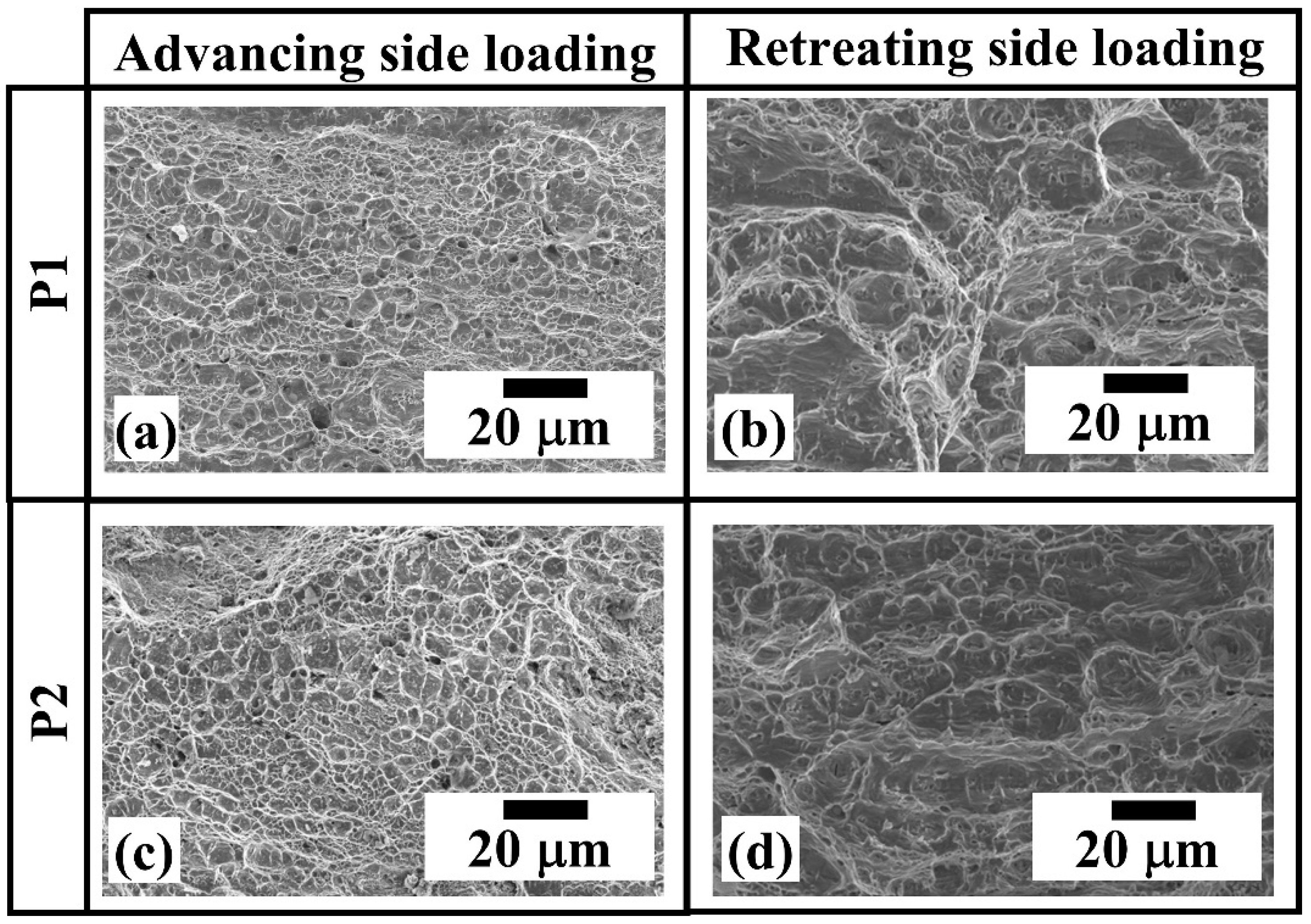
  • The fractographies corresponding to the Inconel 625 and GL E36 steel exhibit less populated dimples with more depth and denser dimples with a shallower depth, respectively, revealing the overall a ductile failure.

Author Contributions

Conceptualization, E.P.B., B.V., G.V.B.L., J.F.d.S. and T.G.R.C.; methodology, E.P.B., B.V., G.V.B.L., C.R.d.L.L., L.B., J.F.d.S., T.G.R.C. and A.D.; validation, E.P.B., B.V. and G.V.B.L.; formal analysis, E.P.B., B.V. and G.V.B.L.; investigation, E.P.B., B.V., G.V.B.L., C.R.d.L.L. and L.B.; data curation, E.P.B., B.V., G.V.B.L., C.R.d.L.L. and L.B.; writing—original draft preparation, E.P.B., B.V., G.V.B.L.; writing—review and editing, E.P.B., B.V., G.V.B.L., T.G.R.C. and A.D.; visualization, E.P.B., B.V., G.V.B.L., C.R.d.L.L. and L.B.; supervision, J.F.d.S., T.G.R.C. and A.D.; project administration, T.G.R.C. and A.D.; funding acquisition, T.G.R.C. All authors have read and agreed to the published version of the manuscript.

Funding

The financial support of CAPES (National Council for Scientific and Technological Development—grant numbers 88881.198810/2018–01 and 23038.000341/2019-71) is acknowledged.

Institutional Review Board Statement

Not required.

Informed Consent Statement

Not applicable.

Data Availability Statement

All necessary information is provided in the manuscript. Further queries can be addressed upon the reasonable request through email to the authors.

Acknowledgments

The authors would like to show their gratitude to Telmo Roberto Strohaecker (LAMEF-PPGE3M-UFRGS) whose presence and wisdom are profoundly missed.

Conflicts of Interest

The authors declare no conflict of interest.

Appendix A

DFLUX, UFILM and UMASFL subroutines for ABAQUS CAE
C------------------------------------------------------------------------------------------------------------
      SUBROUTINE DFLUX(FLUX,SOL,KSTEP,KINC,TIME,NOEL,NPT,COORDS,
      JLTYP,TEMP,PRESS,SNAME)
C
      INCLUDE ‘ABA_PARAM.INC’
C
      DIMENSION COORDS(3),FLUX(2),TIME(2)
      CHARACTER × 80 SNAME
C
C   defined variables
      real xc, yc, zc, platet, pi, sr, pr, ph, offset
      real omega, amuf, delta, p, slt, etam, etah
      real xr, yr, zr, r, tau_stl, tau_in625
      real avratio1, avratio2, avratio3
C
C   defined fixed values
      platet = (−8.2 × 10⁻³)   ! plate thickness (m)
      pi = 3.14159   ! pi value
      sr = 1.8 × 10⁻³   ! shoulder radius (m)
      prr = 4.6 × 10⁻³   ! Pin radius at root (m)
      prt = 3.6 × 10⁻³   ! Pin radius at tip (m)
      pr = 4.1 × 10⁻³   ! (prt + ((prr −prt)/platet) × coords(3)); tool pin radius at the tip
      slt = 4.7 × 10⁻³   ! (prt + ((sr − prt)/platet) × coords(3)); outer radius of shear layer
      ph = 5.5 × 10⁻³   ! Pin height (m)
      offset = (−0.5 × 10⁻³)   ! Offset from top for body flux on pin vertical face
      omega = 52.33    ! Angular velocity (rad/s), 500rpm
      v = 1.0 × 10⁻³   ! Welding speed (m/s), 1 mm/s
      p = 40.0 × 10⁶! Pressure in z-direction (Pa)
      etam = 0.1   ! Efficiency_mechanical
      etah = 0.5   ! Heat partition efficiency
      xc = 0.040   ! X current coordinate initialized (m)
      yc = (−0.11) ! Y current coordinate initialized (m)
      zc = (−0.0)      ! Z current coordinate initialized (m)
      amuf = 0.0
      delta = 0.0
      xr = 0.0
      yr = 0.0
      zr = 0.0
      r = 0.0
      tau1 = 0.0
      tau = 0.0
      avratio1 = 0.0
      avratio2 = 0.0
      avratio3 = 0.0
C
C   Beginning of the code
      if (KSTEP.eq.1) then
C   Distance of a point in cartsian coordinates from tool axis
      xr = COORDS(1) − xc
      yr = COORDS(2) − yc
      zr = COORDS(3) − zc
      r = sqrt(xr2 + yr2)
C
C   Yield shear stress at I.P. temperature
             if ((SOL.gt.0.0)) then
tau_stl = ((((414.76 – 33.61)/(1 + exp((SOL − 433.25)/23.40))) + 33.61)/sqrt(3.0)) × 106
C
tau_in = (((((928.97 − 337.29)/(1 + exp((SOL − 755.02)/178.29))) + 337.29))/sqrt(3.0)) × 106
             endif
             if (tau.le.0.0) tau = 0.0
C
             Body flux around pin (pin volume)
             if ((JLTYP.eq.1).and.(r.ge.pr).and.(r.le.slt)) then
                  if ((zr.ge.0.0).and.(zr.lt.(0.005))) then
C
                  delta = (−0.026 + 0.31 × exp(omega × r/1.87))
                  if (delta.le.0.3) delta = 0.3
                  if (delta.ge.0.7) delta = 0.7
C
                  amuf = 0.5 × exp(−delta × omega × r)
                  if (amuf.le.0.16) amuf = 0.16
                  if (amuf.ge.0.49) amuf = 0.49
C
                  avratio1 = 2.0 × pr/(slt2 − pr2)
C
      FLUX(1) = etah × ((etam × (1 − delta) × tau_al) + (delta × amuf × tau_al × sqrt(3.0))) × ((omega × pr) − (v × (yr/r))) × avratio1
C
                  endif
             endif
C
C   Body flux at pin bottom
             if ((JLTYP.eq.1).and.(r.ge.0.0).and.(r.le.prt)) then
                  if (zr.ge.(5.0 × 10⁻³)).and.(zr.lt.(5.5 × 10⁻³))) then
C
                  delta = (−0.026 + 0.31 × exp(omega × r/1.87))
                  if (delta.le.0.3) delta = 0.3
                  if (delta.ge.0.7) delta = 0.7
C
                  Amuf = 0.5 × exp(−delta × omega × r)
                  if (amuf.le.0.16) amuf = 0.16
                  if (amuf.ge.0.49) amuf = 0.49
C
                  avratio2 = (1/1.6 × 10−3)
C
      FLUX(1) = etah × ((etam × (1 − delta) × tau_in625) + (delta × amuf × tau_in625 × sqrt(3.0))) × ((omega × prt) − (v × (yr/r))) × avratio2
                  endif
             endif
C   Surface flux
             if ((JLTYP.eq.0).and.(r.ge.pr).and.(r.le.sr)) then
             delta = (−0.026 + 0.31 × exp(omega × r/1.87))
             if (delta.le.0.3) delta = 0.3
             if (delta.ge.0.7) delta = 0.7
C
             amuf = 0.5 × exp(−delta × omega × r)
             if (amuf.le.0.16) amuf = 0.16
             if (amuf.ge.0.49) amuf = 0.49
C
             FLUX(1) = etah × ((etam × (1 − delta) × tau) + (delta × amuf × p)) × (omega × r)
endif
      endif
C
      RETURN
      END
C--------------------------------------------------------------------------------------------------
      SUBROUTINE FILM(H,SINK,TEMP,KSTEP,KINC,TIME,NOEL,NPT, CO
      ORDS,JLTYP,FIELD,NFIELD,SNAME,NODE,AREA)
      INCLUDE ‘ABA_PARAM.INC’
      DIMENSION H(2),TIME(2),COORDS(3),FIELD(NFIELD)
      CHARACTER*80 SNAME
C
      H(1) = 0.0     ! initialized heat transfer coeff.
      H(2) = 0.0
C
      SINK = 0.0     ! initialized sink temperature
      if (KSTEP.eq.1) then
             if (JLTYP.eq.0) then
C
             if (TEMP.lt.300.15) TEMP = 300.15
C
             SINK = 300.15
             H(1) = 5.0 × ((TEMP-300.00)0.25)
             endif
      endif
C
RETURN
END
C-------------------------------------------------------------------------------------------------------------------
      SUBROUTINE UMASFL(FLOW,KFLOW,KSTEP,KINC,TIME,NODE,COORDS)
      INCLUDE ‘ABA_PARAM.INC’
      DIMENSION FLOW(KFLOW), TIME(2), COORDS(3)
C
      real zc, zr
      zc = 0.0
      zr = 0.0
C
      KFLOW = 3   !(Assigned flow velocity along x-, y- and z-directions)
C
      if (KSTEP.eq.1) then
      zr = COORDS(3) − zc
C
             if ((zr.ge.0.0).and.(zr.lt.(0.005))) then
             FLOW(1) = (−7.8)   !7800 × 0.001 (along-ve X direction)
             FLOW(2) = 0.0   ! initialized mass flow velocity along y-direction
             FLOW(3) = 0.0   ! initialized mass flow velocity along z-direction
             endif
C
             if ((zr.ge.(0.005)).and.(zr.lt.(0.008))) then
             FLOW(1) = (−8.4) !8400 × 0.001 (along-ve X direction)
             FLOW(2) = 0.0   ! initialized mass flow velocity along y-direction
             FLOW(3) = 0.0   ! initialized mass flow velocity along z-direction
             endif
      endif
RETURN
END

Appendix B

Figure A1a,b present the measured stress-strain curves for the micro-tensile specimens through the steel-Inconel joint thickness, as shown in Figure 1g, for the two welding conditions. In Figure A1a,b, samples 1 to 8 correspond to the micro-tensile specimens, which are taken at different depths from the top surface of the steel plate as indicated in Figure 1g. Samples 1 to 5 are from the steel plate and samples 6 to 8 are from the Inconel plate. The measured values of the yield strength and ultimate tensile strength for the micro-tensile specimens at different depths through the steel-Inconel joint thickness are plotted in Figure 6a,b.
Figure A1. Measured stress-strain curves for tensile testing of the micro-tensile specimens, which are extracted at different depths from the top surface through the steel-Inconel joint thickness for two different welding conditions. (a) tool rotational speed = 500 rpm, travel speed = 1 mm/s, (b) tool rotational speed = 500 rpm, travel speed = 3 mm/s.
Metals 13 00146 g0a1

References

  1. Fernandez, J.R.; Ramirez, A.J. Microstructural Evolution during Friction Stir Welding of Mild Steel and Ni-Based Alloy 625. Met. Mater. Trans. A 2017, 48, 1092–1102. [Google Scholar] [CrossRef]
  2. Maurya, A.K.; Pandey, C.; Chhibber, R. Dissimilar welding of duplex stainless steel with Ni alloys: A review. Int. J. Press. Vessel. Pip. 2021, 192, 104439. [Google Scholar] [CrossRef]
  3. Kumar, S.; Ghosh, P.K. Thermal behaviour of TIG arc surfacing affecting mechanical properties of AISI 4340 steel substrate under static and dynamic loading. Mater. Sci. Eng. A 2019, 773, 138734. [Google Scholar] [CrossRef]
  4. Liu, Y.; Ding, Y.; Yang, L.; Sun, R.; Zhang, T.; Yang, X. Research and progress of laser cladding on engineering alloys: A review. J. Manuf. Process. 2021, 66, 341–363. [Google Scholar] [CrossRef]
  5. Li, S.; Li, J.; Jiang, Z.; Cheng, Y.; Li, Y.; Tang, S.; Leng, J.; Chen, H.; Zou, Y.; Zhao, Y.; et al. Controlling the columnar-to-equiaxed transition during Directed Energy Deposition of Inconel 625. Addit. Manuf. 2022, 57, 102958. [Google Scholar] [CrossRef]
  6. Landell, R.M.; Lessa, C.R.D.L.; Bergmann, L.; dos Santos, J.F.; Kwietniewski, C.E.F.; Klusemann, B. Investigation of friction stir welding process applied to ASTM 572 steel plate cladded with Inconel®625. Weld. World 2020, 65, 393–403. [Google Scholar] [CrossRef]
  7. Argade, G.; Shukla, S.; Liu, K.; Mishra, R. Friction stir lap welding of stainless steel and plain carbon steel to enhance corrosion properties. J. Mater. Process. Technol. 2018, 259, 259–269. [Google Scholar] [CrossRef]
  8. Mahto, M.K.; Kumar, A.; Raja, A.R.; Vashista, M.; Yusufzai, M.Z.K. Cladding of copper sheet on mild steel using friction stir welding. Int. J. Adv. Manuf. Technol. 2021, 118, 3345–3360. [Google Scholar] [CrossRef]
  9. Al-Badour, F.A.; Adesina, A.Y.; Ibrahim, A.B.; Suleiman, R.K.; Merah, N.; Sorour, A.A. Electrochemical Investigation of the Effect of Process Parameters on the Corrosion Behavior of Aluminum-Cladded Pressure Vessel Steel Using a Friction Stir Diffusion Cladding Process. Metals 2020, 10, 623. [Google Scholar] [CrossRef]
  10. Oliveira, J.P.; Duarte, J.F.; Inácio, P.; Schell, N.; Miranda, R.M.; Santos, T.G. Production of Al/NiTi composites by friction stir welding assisted by electrical current. Mater. Des. 2017, 113, 311–318. [Google Scholar] [CrossRef]
  11. Lessa, C.R.D.L.; Landell, R.M.; Bergmann, L.; dos Santos, J.F.; Kwietniewski, C.E.F.; Reguly, A.; Klusemann, B. Two-Pass Friction Stir Welding of Cladded API X65. Procedia Manuf. 2020, 47, 1010–1015. [Google Scholar] [CrossRef]
  12. Li, B.; Shen, Y.; Luo, L.; Hu, W. Effects of processing variables and heat treatments on Al/Ti-6Al-4V interface microstructure of bimetal clad-plate fabricated via a novel route employing friction stir lap welding. J. Alloys Compd. 2016, 658, 904–913. [Google Scholar] [CrossRef]
  13. Anand, R.; Sridhar, V. Studies on process parameters and tool geometry selecting aspects of friction stir welding—A review. Mater. Today Proc. 2020, 27, 576–583. [Google Scholar] [CrossRef]
  14. Hou, W.; Ding, Y.; Huang, G.; Huda, N.; Shah, L.H.A.; Piao, Z.; Shen, Y.; Shen, Z.; Gerlich, A. The role of pin eccentricity in friction stir welding of Al-Mg-Si alloy sheets: Microstructural evolution and mechanical properties. Int. J. Adv. Manuf. Technol. 2022, 121, 7661–7675. [Google Scholar] [CrossRef]
  15. Hou, W.; Shah, L.H.A.; Huang, G.; Shen, Y.; Gerlich, A. The role of tool offset on the microstructure and mechanical properties of Al/Cu friction stir welded joints. J. Alloys Compd. 2020, 825, 154045. [Google Scholar] [CrossRef]
  16. Tavassolimanesh, A.; Nia, A.A. A new approach for manufacturing copper-clad aluminum bimetallic tubes by friction stir welding (FSW). J. Manuf. Process. 2017, 30, 374–384. [Google Scholar] [CrossRef]
  17. Mahto, M.K.; Kumar, A.; Raja, A.R.; Vashista, M.; Yusufzai, M.Z.K. Friction stir cladding of copper on aluminium substrate. CIRP J. Manuf. Sci. Technol. 2021, 36, 23–34. [Google Scholar] [CrossRef]
  18. Kar, A.; Vicharapu, B.; Morisada, Y.; Fujii, H. Elucidation of interfacial microstructure and properties in friction stir lap welding of aluminium alloy and mild steel. Mater. Charact. 2020, 168, 110572. [Google Scholar] [CrossRef]
  19. Lakshminarayanan, A.; Harikrishna, K.L. Role of Overlap Ratio on the Microstructure of Friction Stir Multiseam Cladded Copper-Stainless Steel Lap Joints. Mater. Sci. Forum 2020, 979, 102–106. [Google Scholar] [CrossRef]
  20. Kimura, M.; Nakashima, K.; Kusaka, M.; Kaizu, K.; Nakatani, Y.; Takahashi, M. Joining phenomena and tensile strength of joint between Ni-based superalloy and heat-resistant steel by friction welding. Int. J. Adv. Manuf. Technol. 2019, 103, 1297–1308. [Google Scholar] [CrossRef]
  21. Cheepu, M.; Che, W.S. Characterization of Interfacial Microstructure in Friction Welds Between Inconel 718 and SM45C Steel. Trans. Indian Inst. Met. 2020, 73, 1567–1571. [Google Scholar] [CrossRef]
  22. Meshram, S.; Mohandas, T.; Reddy, G.M. Friction welding of dissimilar pure metals. J. Mater. Process. Technol. 2007, 184, 330–337. [Google Scholar] [CrossRef]
  23. Kar, A.; Kailas, S.V.; Suwas, S. Effect of Mechanical Mixing in Dissimilar Friction Stir Welding of Aluminum to Titanium with Zinc Interlayer. Trans. Indian Inst. Met. 2019, 72, 1533–1536. [Google Scholar] [CrossRef] [Green Version]
  24. Das, H.; Jana, S.S.; Pal, T.K.; De, A. Numerical and experimental investigation on friction stir lap welding of aluminium to steel. Sci. Technol. Weld. Join. 2013, 19, 69–75. [Google Scholar] [CrossRef]
  25. Das, A.; Shome, M.; Goecke, S.-F.; De, A. Numerical modelling of gas metal arc joining of aluminium alloy and galvanised steels in lap joint configuration. Sci. Technol. Weld. Join. 2016, 21, 303–309. [Google Scholar] [CrossRef]
  26. Bang, H.-S.; Hong, S.M.; Das, A.; Bang, H.-S. Study on the Weldability and Mechanical Characteristics of Dissimilar Materials (Al5052-DP590) by TIG Assisted Hybrid Friction Stir Welding. Met. Mater. Int. 2019, 27, 1193–1204. [Google Scholar] [CrossRef]
  27. Lemos, G.V.B.; Farina, A.B.; Nunes, R.M.; da Cunha, P.H.C.P.; Bergmann, L.; dos Santos, J.F.; Reguly, A. Residual stress characterization in friction stir welds of alloy 625. J. Mater. Res. Technol. 2019, 8, 2528–2537. [Google Scholar] [CrossRef]
  28. Lemos, G.V.B.; Farina, A.B.; Piaggio, H.; Bergmann, L.; Ferreira, J.Z.; dos Santos, J.F.; Voort, G.V.; Reguly, A. Mitigating the susceptibility to intergranular corrosion of alloy 625 by friction-stir welding. Sci. Rep. 2022, 12, 3482. [Google Scholar] [CrossRef]
  29. da Cunha, P.H.C.P.; Lemos, G.V.B.; Bergmann, L.; Reguly, A.; dos Santos, J.F.; Marinho, R.R.; Paes, M.T.P. Effect of welding speed on friction stir welds of GL E36 shipbuilding steel. J. Mater. Res. Technol. 2018, 8, 1041–1051. [Google Scholar] [CrossRef]
  30. Lemos, G.V.B.; Cunha, P.H.C.P.; Nunes, R.M.; Bergmann, L.; dos Santos, J.F.; Clarke, T. Residual stress and microstructural features of friction-stir-welded GL E36 shipbuilding steel. Mater. Sci. Technol. 2017, 34, 95–103. [Google Scholar] [CrossRef]
  31. Vicharapu, B.; Lemos, G.V.B.; Bergmann, L.; dos Santos, J.F.; De, A.; Clarke, T. Probing underlying mechanisms for PCBN tool decay during friction stir welding of nickel-based alloys. Tecnol. Metal. Mater. Min. 2021, 18, e2455. [Google Scholar] [CrossRef]
  32. Kanan, L.F.; Vicharapu, B.; Bueno, A.F.B.; Clarke, T.; De, A. Friction Hydro-Pillar Processing of a High Carbon Steel: Joint Structure and Properties. Met. Mater. Trans. B 2018, 49, 699–708. [Google Scholar] [CrossRef]
  33. Vicharapu, B.; Kanan, L.F.; Clarke, T.; De, A. An investigation on friction hydro-pillar processing. Sci. Technol. Weld. Join. 2017, 22, 555–561. [Google Scholar] [CrossRef]
  34. Baker, H. Section 1 Introduction to Alloy Phases Diagrams. In AST Handbook; ASM International: Almere, The Netherlands, 1992; Volume 3, pp. 1.1–1.29. [Google Scholar]
  35. Rodriguez, J.; Ramirez, A. Microstructural characterisation of friction stir welding joints of mild steel to Ni-based alloy 625. Mater. Charact. 2015, 110, 126–135. [Google Scholar] [CrossRef]
  36. Ayer, R.; Jin, H.; Mueller, R.; Ling, S.; Ford, S. Interface structure in a Fe–Ni friction stir welded joint. Scr. Mater. 2005, 53, 1383–1387. [Google Scholar] [CrossRef]
Figure 1. (a) Schematic three-dimensional and two-dimensional sectional views with plate dimensions of the overlapped GL E36 steel and Inconel 625 for FSLW. The horizontal dashed and vertical dotted lines in the two-dimensional sectional view are the locations for the microhardness measurement. (b,c) Microstructures of as-received (b) GL E36 steel, and (c) Inconel 625. (d) Three-dimensional and sectional view of pcBN tool with dimensions. (e,f) Schematic view of transverse tensile specimens with (e) steel and (f) Inconel 625 plates being engaged separately during actual testing. The hatched portion in (e,f) indicates the lap joint stir zone (SZ). (g) Schematic view of longitudinal micro-tensile specimens taken at different heights from the stir zone. The thickness of the micro-tensile specimens is 0.5 mm.
Metals 13 00146 g001
Figure 2. Computed temperature isotherms (a,b), and the computed and experimentally measured thermal cycles (c,d) for a constant tool rotational speed of 500 rpm and at two tool travel speeds of 1 mm/s (a,c) and 3 mm/s (b,d).
Metals 13 00146 g002
Figure 3. (a) Macrograph of joint cross-section for a tool rotational speed of 500 rpm and travel speed of 1 mm/s and, the zoomed views of (b) joint interface and (c) stir zone; (d) macrograph of joint cross-section for a tool rotational speed of 500 rpm and travel speed of 3 mm/s, and the zoomed views of (e) joint interface and (f) stir zone. “B”, “AF”, “M” and “W” in Figure (c,f) refer to the bainite, acicular ferrite, martensite, and Widmanstätten ferrite phases, respectively.
Metals 13 00146 g003
Figure 4. SEM images (a,c) of joint cross-sections, and energy dispersive spectroscopy (EDS) line scans (b,d) along the red lines on the corresponding SEM images.
Metals 13 00146 g004
Figure 5. (a,b) Measured hardness distributions above (steel side) and below (Inconel 625 side) the joint interface (please refer to Figure 1d). (c) Measured hardness distribution at the weld center in the thickness direction from the top to bottom surface of the weld. (d,e) Measured longitudinal residual stresses on the (d) steel and the (e) Inconel 625 surfaces. Measurements are done along the joint transverse sections. All the joints are made at a tool rotational speed of 500 rpm. Travel speeds are (a) 1 mm/s and (b) 3 mm/s.
Metals 13 00146 g005
Figure 6. (a) Measured strengths from the micro tensile test specimens at different depths in the stir zone from the steel top surface to the Inconel 625 bottom surface. The travel speeds for the weld are (a) 1 mm/s, and (b) 3 mm/s. (c) Measured lap-shear strength of the joints made at travel speeds of 1 mm/s and 3 mm/s. The tool rotational speed is kept at 500 rpm for all welds.
Metals 13 00146 g006
Figure 7. Fractured lap shear test specimens of the weld made at a tool travel speed of 1 mm/s (a,b), and 3 mm/s (c,d) under the advancing side loading (a,c), and retreating side loading (b,d). The tool rotational speed is kept constant at 500 rpm for all welds. Regions encompassed by a yellow dashed circle are used for fractography analysis.
Metals 13 00146 g007
Figure 8. (ad) Fractographies along the regions highlighted by yellow dashed circles in Figure 7 of lap-shear test specimens.
Metals 13 00146 g008
Table 1. Chemical composition (% by weight) of Inconel 625 and GL E36 steel.
NiCrFeMoNbCoMnAlTiSiC
GL E36-0.06Bal.0.0060.025-1.40.0270.0030.390.17
Alloy 625Bal.21.74.78.63.380.030.090.130.180.180.015
Table 2. Properties of Inconel 625 and GL E36 steel [T in K].
Inconel 625 [31]GL E36 Steel [33]
ρ (kg/m3)84007800
k, (W/m K)5.06 + 0.02T;
for 300 K ≤ T ≤ 1255 K
63 − 0.03T; for T < 1073 K
27[1 + (T − 1073)/(1175 − 1073); for T ≥ 1073 K
CP, (J/kg K)381.83 + 0.21T;
for 300 K ≤ T ≤ 1365 K
347.3 + 62.3 exp(T/471.7); for T < 1075 K
962.3; for T ≥ 1075 K
σY, (MPa)337.29 + (928.97 − 337.29)/(1 + exp(T − 755)/178.29);
for 300 K ≤ T ≤ 1500 K
190.12 − 0.1503 T; for T < 1500 K
10.0; for T ≥ 1500 K
Disclaimer/Publisher’s Note: The statements, opinions and data contained in all publications are solely those of the individual author(s) and contributor(s) and not of MDPI and/or the editor(s). MDPI and/or the editor(s) disclaim responsibility for any injury to people or property resulting from any ideas, methods, instructions or products referred to in the content.

