Article

Comprehensive Estimation of Changes in the Microgeometry of Steel 45 by Ultrasonic Plastic Deformation with a Free Deforming Element

by
Dmitriy S. Fatyukhin
*,
Ravil I. Nigmetzyanov
,
Vyacheslav M. Prikhodko
,
Aleksandr V. Sukhov
and
Sergey K. Sundukov
Department of “Technology of Construction Materials”, Moscow Automobile and Road Construction State Technical University (MADI), Leningradsky Prospect, 64, 125319 Moscow, Russia
*
Author to whom correspondence should be addressed.
Metals 2023, 13(1), 114; https://doi.org/10.3390/met13010114
Submission received: 25 November 2022 / Revised: 30 December 2022 / Accepted: 4 January 2023 / Published: 6 January 2023

Abstract

:
A method of ultrasonic surface plastic deformation is widely used to change the properties of the surface layers of metal products. Under the influence of this type of treatment, the structure of the material changes, microhardness increases, roughness decreases, internal tensile stresses are removed, and compressive stresses are created. Now many types of ultrasonic surface plastic deformation have been developed, which differ in the degree of impact on the material. The object of this paper is to study the change in the microgeometry of steel 45 (ASTM M1044; DIN C45; GB 45) under the action of ultrasonic plastic deformation by a free deforming element (indenter in the form of a surface rolling ball). During the study, factors that have the greatest influence on the change in the microgeometry of the sample during treatment were identified. These include the initial roughness of the sample, the number of passes of the indenter, the feed of the indenter, the force with which the indenter is pressed to the treated surface, and the amplitude of the oscillations of the ultrasonic horn. The paper presents the dependences of changes in the main roughness parameters on the above factors. The value of the initial roughness at which it is possible to obtain a uniform surface microrelief is determined. The optimization of treatment parameters providing a change in the height and step parameters of roughness was carried out. Recommendations for choosing the most effective technological modes of ultrasonic treatment of steel 45 with a surface rolling ball are given.

1. Introduction

The increase in the resource of structural elements and parts is carried out in engineering practice in various areas. It is the creation of new heavy-duty materials, modification and improvement of properties of existing metals and alloys due to various alloying additions, engineering solutions at the design stage, etc. Technological methods for improving the operational characteristics of various parts, associated with the operation of surface plastic deformation (SPD), not requiring the removal of a layer of the material from the workpiece [1], take a special place in this series. As a result of this treatment, the surface layer is strengthened, and roughness is reduced, which leads to an increase in wear resistance, and a decrease in fatigue and corrosionfatigue strength.
One of the effective methods for solving problems that arise during SPD is the application of ultrasonic vibrations on a working tool. That makes it possible to significantly modify the properties of the surface layers of parts by high-energy exposure to harmonic vibrations of ultrasonic frequency, control changes in the microgeometry of the formed surface, its hardness, degree of strain hardening, and obtain a regular microrelief [2,3,4,5,6,7,8].
The most common use of ultrasonic surface plastic deformation (USPD) is in two versions—as a deforming element (indenter) rigidly connected to an ultrasonic oscillatory system (UOS) and free working tools [9].
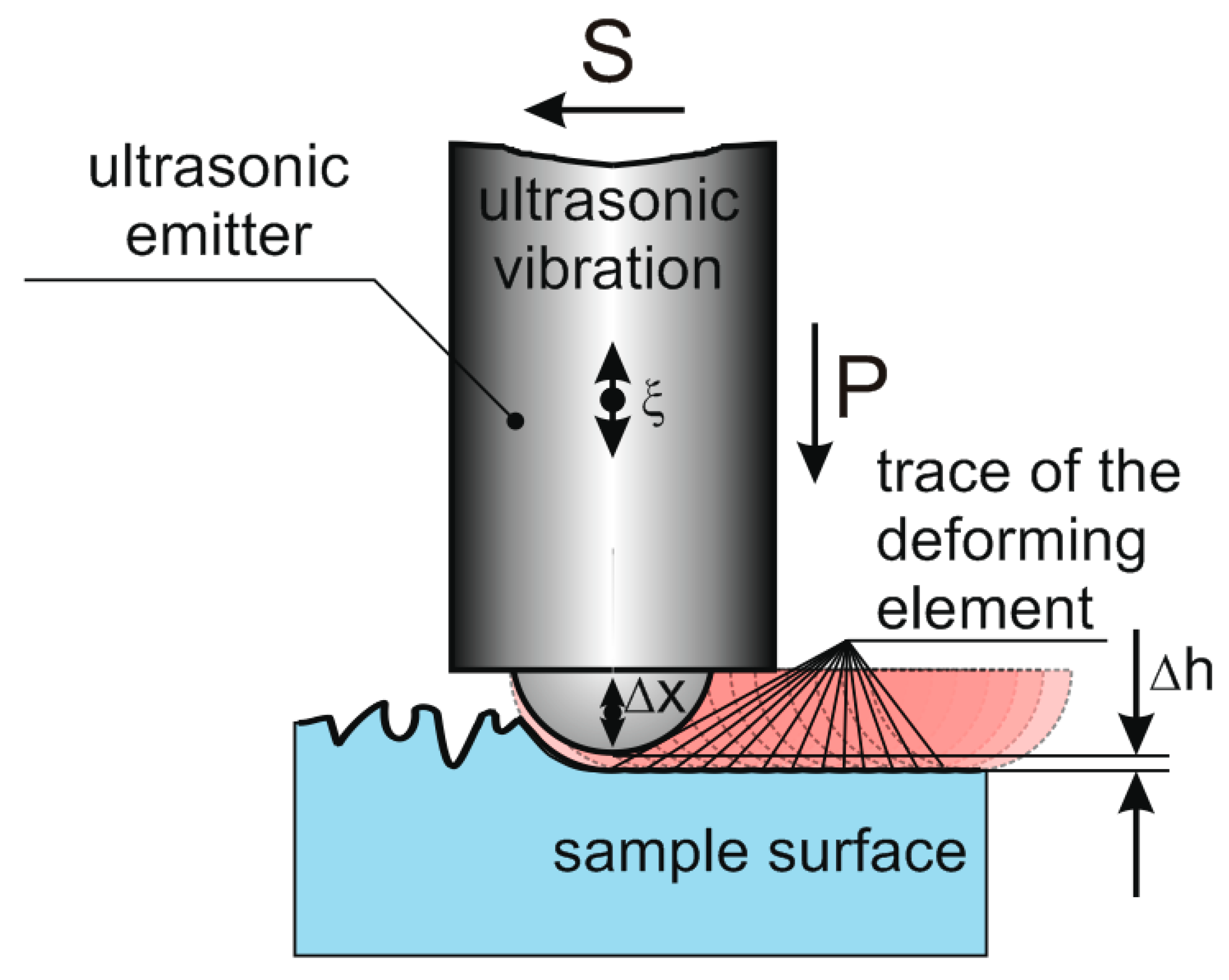
Treatment with a rigidly connected indenter—USPD—was first proposed in 1964 by I.I. Mukhanov (Figure 1) [10]. In 1975 I.A. Stebelkov proposed a method of treatment with free working bodies—ultrasonic vibration shock treatment (UVST) (Figure 2) [11]. USPD results in better surface uniformity and a greater reduction in surface roughness than UVST. At the same time, UVST makes it possible to obtain a greater depth of the hardened layer [3].
Rigid indenter treatment is currently being actively researched, and a distinction can be made between technologies such as ultrasonic surface rolling processing (USPR) based on ultrasonic impact peening (UIP), ultrasonic nanocrystal surface modification (UNSM), and its combinations with other treatments.
USPR is a severe plastic deformation surface method that is an integration of ultrasonic impact peening and deep rolling methods.
This method was proposed in [12] to solve the problem of tool wear in the treatment of steel 40 Kh [13]. The results showed that tool wear is reduced (the tool life increased by 800 times). Additionally, the surface roughness decreases (up to 0.06 microns), the microhardness increases (from 280 HV to 405 HV, i.e., by 52.6%), and the compressive residual stresses can reach −846 MPa.
The possibility of using the USPR method for various materials isbeing actively researched. For example, in [14] the possibilities of ultrasonic rolling of steel 25CrNi2MoV are shown. The results showed that ultrasound makes it possible to bring the depth of the layer with plastic deformation to 29 µm, while the maximum load is 1200 N. In this case, the nature of wear changes from adhesive to abrasive, and the coefficient of friction and the amount of wear decrease in the case of fretting wear on the surface.
However, in this paper, one amplitude value is considered, despite the fact that the oscillation amplitude is one of the most important ultrasonic treatment parameters. This does not allow us to talk about a complete study of the hardening process of 25CrNi2MoV steel.
A study [15] describes the rolling of a high-entropy alloy (HEA) CrMnFeCoNi, which is treated by ultrasonic rolling after production by laser additive manufacturing and turning. The results showed that after USRP there was a significant increase in hardness to 352.28 HV, while the hardness immediately after production was 231.52 HV. Samples after USRP demonstrate a low coefficient of friction and low losses, showing better wear resistance.
In [16], the effect of ultrasonic rolling on austenitic motor valve steel 33Cr23Ni8Mn3N (23-8N) is considered. The results showed that ultrasonic treatment allows for obtaininghigher compressive residual stresses and lower surface roughness of the material. Herewith, with an increase in frequency from 20 to 30 kHz, the highest values of these parameters are achieved. Additionally, for treated surfaces, the coefficient of friction is reduced, and wear resistance and fatigue strength are increased. However, authors consider only an amplitude of 10 μm. This amplitude is shown as optimal based on the results of experiments with titanium alloy HIP Ti–6Al–4V [17,18,19], where ultrasound also increases microhardness, wear resistance, and other parameters. It should be noted that the amplitude intervals were selected with an uneven interval between the points (15, 10, and 8 µm).
A further development of the USRP method is the ultrasonic nanocrystal surface modification (UNSM) method. The new method differs from the previous method by a lower pressing force and increased amplitude.
Ref. [20] describes the influence of UNSM on S45C steel. The authors considered three treatment modes, in which the number of vibration shocks was 34,000, 45,000, and 68,000 times/mm2. In the mode of 68,000 times/mm2, the smallest roughness is achieved, the fatigue strength increases by 33%, and the microhardness increases.
In [21], the influence of UNSM on the process of nitriding steel 300 M is described. The UNSM pretreatment increased the efficiency of nitriding by forming a plastic deformation surface layer with refined and deformed lath martensite, which provided more channels for nitrogen diffusion. Aftertreatment, samples showed the best corrosion resistance, which is the result of the formation of a thicker nitride layer and an increase in nitrogen concentration.
The UNSM treatment of steel 304 [8,22,23] has also shown its efficiency over shot peening, deep rolling, or laser impact treatment. In [23] it was shown that samples treated with UNSM have a longer service time, as well as the smallest grain size, in comparison with shot peening (SP) treatment and the SP + UNSM combination. This results in the greatest fatigue life at various stress levels.
In addition, the UNSM method was used to treat samples from the AlSi10Mg alloy produced on a 3D printer [24]. Ultrasonic treatment showed its effectiveness, reducing the roughness of the sample from 18 µm to 3.5 µm, while the amplitude was 12 µm.
Studieswith various combinations of existing treatment methods are being actively carried out now.
For example, in [25] the thermal stability of the compressive residual stress increased, as a result of the effect of hot ultrasonic rolling on ultra-high-strength steel 45CrNiMoVA.Ultrasonic treatment was carried out at a pressing force of 1300 N, an amplitude of 8 μm, and a frequency of 28 kHz. The highest efficiency is achieved at temperatures of 150–200 °C, where the surface intact after ultrasonic hot rolling is the best. However, the paper does not provide criteria for optimizing the treatment efficiency.
The process similar to the UVST is a process the authors call the ultrasonic vibration-assisted ball-burnishing process (UVABB) [26,27,28].The purpose of this type of treatment is to reduce roughness, while it is possible to reduce the required pressing force of the tool to the surface to be treated, reduce friction, and increase the operating time of the indenter.
Basically, it works on the subject of UVST, the issues of changing the structure and physical and mechanical properties of materials are considered in detail, while little attention is paid to the microgeometry of the surface. Generally, information is limited to data about the minimum height of microroughness obtained by this method.
The treatment methods discussed above make it possible to improve the surface properties of products from a wide variety of materials. However, in considered papers, treatment parameters even for similar materials can be different. In this regard, the object of this paper is to determine rational treatment parameters bythe ultrasonic vibration shock treatment (UVST) method in order to form the required surface roughness.

2. Materials and Methods

2.1. Materials

A hot-rolled rod made of structural steel 45 with a diameter of 42 mm was used for experimental studies. Cylindrical samples 185, …, 190 mm long were cut from the rod. The chemical composition of the steel was determined by optical-emission spectral analysis using spectrometers Foundry-Master LAB (LLC SINERCON, Moscow, Russia). The chemical composition of steel is given in Table 1.
The samples were treated on a 16E20 normal precision lathe of the Alma-Ata Machine Tool Plant. A surface layer 0.75 mm thick was removed from the samples, after which treatment was carried out with a contour cutter with the parameters: cutter feed S = 0.24 mm/r, rotation frequency n = 560 rpm, cutting depth t = 0.25 mm. During treatment with a contour cutter with a vertex radius of 0.4 mm, a regular surface microrelief was obtained with surface roughness parameters Ra = 4.59 µm, Rz = 23.8 µm, Rmax = 27.6 µm, Sm = 0.193 mm, S = 0.051 mm, t30 = 20.7%. Obtained values correspond to semi-finishing treatment.
Grooves were made with a depth of 3, …, 4 mm on the samples every 30 mm, which are needed to divide the surface of the sample into parts.
Three samples of the same type were made from steel 45 with these treatment parameters. Each sample was used to determine the effect of one of the factors (the feed, the vibration amplitude) on changes in surface roughness after ultrasonic surface deformation.
Additionally, 5 samples were made to determine the effect of the initial roughness and the number of passes of the deforming element on the roughness after ultrasonic treatment. In this case, samples were divided into parts, which were treated by turning with a rotation frequency of n = 560 rpm, a depth of cut t = 0.25 mm with different feeds: 0.1; 0.24; 0.29; 0.34, 0.38 mm/rev. That made it possible to vary the initial roughness in terms of the Ra parameter and obtain the values: 1.3; 4.59; 6.82; 9.6; 22.6 µm.
Each sample passed from 1 to 5 cycles of ultrasonic surface plastic deformation. The scheme of multipass treatment of samples is presented in the next section.
Before ultrasonic treatment, the samples were normalized at T = 860 °C.

2.2. Experiment Scheme and Equipment

Ultrasonic surface plastic deformation was carried out according to the scheme shown in Figure 3. An ultrasonic oscillatory system with a waveguide concentrator was fixed in the tool holder of the lathe. A PMS-2.0-22 rod three-half-wave magnetostrictive oscillatory system (LLC “Inlab”, St. Petersburg, Russia) was used. It consisted of a magnetostrictive transducer made of iron–cobalt alloy (Fe: 47–50 wt.%, Co: 48–50 wt.%, V: 1.5–2 wt.%), located in a water-cooling jacket, with a titanium alloy waveguide concentrator soldered to its end.
To ensure that the indenter is pressed to the treated surface with the necessary force, the oscillating system is equipped with a spring that provides the calculated pressing force.
A step titanium emitter with a diameter of the emitting surface of Ø15 mm, which has a coefficient of increase in the oscillation amplitude ky = 2, was connected to the waveguide of the oscillatory system by means of a threaded connection. At the working surface of the emitter, a blind spherical hole is made, into which an indenter (a ball from a ball bearing) made of steel ShKh15 GOST 801-78 (analog 100Cr6 DIN 17230) with a diameter of 11 ± 0.1 is installed with a gap. Such a design solution allows you to quickly change the indenter in case of wear.
The oscillating system was powered by a UZG2-22 generator (LLC Apfalina, Moscow, Russia), with a maximum output power of up to 2 kW, which is required to achieve high oscillation amplitudes. The generator had automatic frequency and amplitude control functions that made it possible to change the resonant frequency with a change in the mechanical load at the end of the emitter.
For measuring the amplitude of vibrational displacements of the end of the waveguide concentrator ξmax, an electrodynamic vibrometer was used. It is a magnetic system consisting of acircular permanent magnet (TU 48-1301-16-73) and a measuring coil on a Plexiglas frame containing 800 turns of PEV2-0.1 wire and disk magnetic circuits. The vibrometer was placed on the waveguide of the rod oscillatory system.
To estimate ξmax, the vibrometer was calibrated by the optical method using a microscope. During the use of the oscillatory system, the signal from the electrodynamic vibrometer was transmitted to a voltmeter, the scale of which was calibrated using a microscope. This method allows you to control the amplitude of the end of the waveguide concentrator according to the indication of the voltmeter when the tool transmits vibrations to the indenter.
The sample was fixed in the lathe chuck from one end and was pressed by a lathe center from the other end. To prevent the transfer of high-frequency vibrations to the lathe chuck and center, they are equipped with fluoroplastic vibrationinsulation pads.
The lathe spindle speed was set to n = 560 rpm, which ensures the processing speed Vr ≈ 1.2 m/s for the chosen sample. An analysis of the literature [29,30] and data from preliminary experiments show that a change in the spindle frequency has little effect on the change in hardness and roughness. When varying the speed in a wide range, the roughness at constant other parameters changed by no more than 8, …, 12%, and the change in hardness did not exceed 10%. In addition, the temperature of the indenter (ball) also increases significantly with an increase in speed.

2.3. Methodology for Ultrasonic Surface Plastic Deformation

The study of the influence of the number of passes on the properties of the deformed layer was carried out as follows.
Based on the analysis of SPD studies and the data of preliminary experiments, the maximum number of tool passes, equal to five, was chosen. The choice is justified by the greatest changes in hardness and roughness, which are observed during one pass of the tool. When the number of passes is 3, …, 4, the overhardening of the surface begins, which leads to the appearance of microcracks and spalling of the surface layer of the sample.
The indenter of the oscillatory system was pressed to the right point of the sample (Sample part 6) with a preassigned force. The pressing force was regulated by a spring. Required treatment parameters were set on the lathe, then the lathe was turned on. The working tool (indenter) sequentially treated sample parts 6-5-4-3-2 with the left feed, then 3-4-5-6 with the right feed, then 6-5-4 with the left feed, then 5-6 with the right feed, and finally 6 with the right feed. Thus, sample part 1 was not treated by plastic deformation (control sample), sample part 2 was treated with one tool pass, sample part 3—with two passes, sample part 4—with three passes, sample part 5—with four passes, and sample part 6—with five passes.
Since the main treatment parameters are S feed, oscillation amplitude ξ, and pressing force FN, three series of experiments were carried out on the effect of these parameters on the properties of steel 45 according to the described method.
In each series of five experiments, only one of the parameters changed, and the others remained constant. In the first series, the feed S was changed, in the second the oscillation amplitude ξ, and in the third, the pressing force FN.

2.4. Estimation of Structure and Surface Properties

Standard roughness parameters were evaluated for control and treated samples. Certain roughness parameters given in this study correspond to EN ISO 4287:1997, including the arithmetic mean deviation (Ra), ten-point height (Rz), and maximum peak-to-valley height (Rtm), while the others correspond to GOST 2789-73, including the average pitch of the profile roughness (Sm), the average pitch of local peaks (S), and the relative reference length of the profile (tp, where p is the level of the profile section). Measuring the level of the profile section was taken equal to 30%.
Roughness parameters were measured on a Model 130 profilometer (Proton JSC, Zelenograd, Russia).
The operation of the profilometer analyzes the roughness of the measured surface with an inductive sensor at a constant speed. The sensor probe is a diamond needle. Then, the movement of the probe is converted from an analog to a digital signal with further processing of the signal on the computer. The tracing length is up to 12.5 mm. The measurement error limits for the roughness parameter do not exceed 6% in the range from 0.001 to 0.1 µm, 4% in the range from 0.1 to 1 µm, and vary from 2% to 0.08% in the range from 1 to 3000 µm (according to GOST 8.296-2015).
Numerical and graphic processing of the measurement results was carried out in statistical software.Since the spread of the obtained values did not exceed the 3-sigma rule, the data can be considered reliable While the dependences of the roughness parameters were plotted, the values were taken as the arithmetic means of five measurements in different parts of the sample. The fact that the profilometer measures 10 basic lengths in one measurement allows us to speak of a total number of 50 measurements of roughness parameters at one point.This, in turn, provides a confidence level of 0.95 for the values obtained. The obtained experimental data were approximated by the method of least squares.

3. Results and Discussion

3.1. Feed

In the first series of experiments, the influence of the longitudinal feed Sx on the roughness parameters Ra, Rz, Rtm, Sm, S, and tp was studied.The experimental results are shown in Figure 4. As expected, with a decrease in the feed rate, a significant decrease in roughness is observed.
During ultrasonic plastic deformation, the deforming element moves equidistantly to the profile of the treated surface. In the case under consideration, the trajectory of movement is a spiral. The smaller the pitch of the spiral, the greater the uniformity and depth of hardening that can be achieved. The pitch is determined by the quantity of longitudinal feed Sx.
Despite the fact that the rational choice of feed is based not only on providing the greatest impact on the surface but also on reducing the treatment time, the feed value must be minimal in order to achieve the maximum technological effect.
The results of the experiments, shown in Figure 4, show that for the given material and treatment conditions it is the most rational to use a feed rate of no more than 0.3 mm/rev. With this value, the roughness parameters Ra, Rz, Rtm, Sm, and S are significantly reduced, and the relative reference length increases (Tables S1–S6).This is explained by the fact that the impact traces of the deforming element overlap and form a regular surface microrelief. Exceeding this value leads to a sharp decrease in the quality of treatment. However, the use of feeds up to 0.2 mm/rev significantly reduces the productivity of treatment and can only be applied in case of increased requirements for surface finish.

3.2. Pressing Force

The specificity of the considered method of ultrasonic treatment is the impact of the deforming element, which is normal towards the surface profile. At high pressing forces, the deforming element and the emitter are made in phase oscillations, i.e., the ball does not come off the treated surface and the treatment conditions are close to rolling. Herewith, the main mechanism of deformation is the pressure of the ball (indenter) on the treated surface, created by the vibrations of the emitter.
With a decrease in the pressing force of the indenter to the surface, a gap appears between them. This is related to the fact that, after activation of vibrations, the ball, pressed to the surface with an initial force is indented the surface and deforms it by ΔS, while the ball does not have time to move at the speed of the emitter due to its inertia. There is a break in the contact between the emitter and the ball, i.e., the deforming element begins to oscillate between the emitter and the treated surface. The ball receives an impulse from the emitter and moves with acceleration to the treated surface, hits it, performs a deformation work, rebounds, and moves until it collides with the emitter. Then, the cycle repeats.
The period of impact of the ball on the surface will be directly proportional to ΔS and inversely proportional to the average speed of the ball. Considering that the speed of the ball will also depend on ΔS, the period of oscillation and the impulse of force will be proportional to the size of the gap, which is determined by the initial force of the static press.
Accordingly, with a decrease in the pressing force, the amplitude and impact force of the ball increase, and the frequency of impacts decreases.
Observations of ultrasonic treatment by a free deforming element, carried out using a high-speed film camera, made it possible to study the dynamics of the indenter movement. The experiment was carried out at an emitter oscillation frequency of 21.2 kHz and an amplitude of oscillation displacements of the emitter = 20 μm. As an example, in Figure 5 the dynamics of the ball movement aregiven for pressing forces of 5 N, 55 N, and 105 N.
At various pressing forces, the nature of the movement of the deforming body (ball) is quasi-periodic. An analysis of film frames shows that with a force of 5 N, the impact frequency is approximately 550 Hz, and the range (doubled amplitude) of oscillations is 20, …, 30 μm. With an increase in the pressing force to 55 N, the impact frequency increases to 1400 Hz, and the range is 9, …, 12 µm. At the pressing force 105 N, the impact frequency increases to 6000 Hz, and the range is 6, …, 9 µm.
The obtained data on the change in the roughness parameters at different pressing forces of the deforming element to the treated surface are shown in Figure 6.
On the given functions, the roughness values at the pressing force FN = 0 N correspond to the initial value of the sample roughness. With small pressing forces, the frequency of impacts of the deforming element is low, as a result of which there is no uniform significant change in roughness. In the range FN = 5, …, 100 N, the greatest changes occur. When FN = 100, …, 120 N is reached, the process stabilizes, and a further increase in the pressing force does not lead to a significant result. At such values of FN, the deforming element stops detaching from the emitter surface and the change in roughness is insignificant.

3.3. Emitter Oscillation Amplitude

The emitter oscillation amplitude ξmax largely determines the force interaction of the deforming element and the treated surface. From the point of view of microrelief formation, a significant factor is the creation of a quasi-viscous friction mode [29,30], in which the friction force between elements of the system “treated surface—deforming element—emitter” is reduced under the influence of high-frequency oscillations.
Obtained functions of the roughness parameters on the emitter oscillation amplitude are shown in the Figure 7.
Without oscillations, i.e., with the emitter oscillation amplitude ξmax = 0 μm, the type of treatment corresponds to rolling and does not lead to appreciable results at low pressing forces. With the activation of vibrations, changes occur in the interaction of the deforming element and the surface to be treated. Operating conditions of the deforming element change even at small oscillation amplitudes ξmax = 2, …, 4 µm. A significant reduction in roughness is observed at oscillation amplitudes up to ξmax = 8, …, 10 µm. With a further increase in the amplitude, no changes in microgeometry occur.
In addition, it should be noted that without oscillations (ξmax = 0 μm), the deforming element is rapidly heated to temperatures above 300–400 °C. As a result of heating, the resource of the deforming element is reduced. At high amplitudes (ξmax = 15 µm), the heating is not so significant, and the temperature does not exceed 150 °C.
Since the increase in the oscillation amplitude is proportional to the expended power, it is most advantageous to choose the amplitudes ξmax = 9, …, 10 µm, which provide the required technological effect.

3.4. Initial Sample Roughness and Number of Indenter Passes

One of the issues to be solved during the setting of research objectives was to identify the initial roughness of the sample, at which uniform treatment of the entire surface occurs, i.e., at which the deformation action reaches the profile valleys.
During treatment of samples with an initial roughness corresponding to semi-finish turning (Rtm < 100 μm), with an increase in the number of passes of the deforming element, a monotonous decrease in the height of microroughness occurs, and the relative reference length of the profile increases. The greatest changes occur during the first and second passes of the deforming element (Figure 8). With an increase in the number of passes more than three, the height of the roughness begins to increase slightly. This is due to the formation of surface hardening, as a result of which pores, submicrocracks, and other defects appear in the material.
A different situation is observed during the treatment of samples with an initial roughness corresponding to rough turning (Rtm > 100 μm). With an increase in the number of passes of the deforming element, a monotonous decrease in the height of microroughness occurs, and the relative reference length of the profile increases, while the average pitch of the profile roughness changes insignificantly. Observations show that with such sizes of microroughness, only surface peaks are processed. The impact of the tool does not reach the valleys, as a result of which a regular specific surface microrelief is formed.
Special studies of the achieved profile for friction and wear have not been carried out, but it is possible that the regular micro-pits of the profile can serve as oil pockets. In this case, it becomes possible to increase the product life (similar to honing).
The obtained functions show that, at an initial roughness up to Rtm = 40 μm, it does not significantly affect the roughness resulting from surface plastic deformation. So, for all samples with an initial roughness Ra = 1.3, …, 6.9 μm after three passes of the indenter, the arithmetic mean deviation of the profile was Ra = 0.101, …, 0.174 μm.
As an example, there are changes in microprofiles of the surface of samples with an initial roughness Rtm = 27.6 µm and Rtm = 108 µm (Figure 9).

4. Conclusions

As a result of the studies on the effect of ultrasonic surface plastic deformation by a free deforming element on the surface roughness of samples made of steel 45, functions were obtained that make it possible to determine a rational processing mode depending on the feed and pressing force of the deforming element, the amplitude of the emitter oscillations, the initial roughness and the number of passes of the deforming element.
As the experimental data in Figure 4 shows, when processing steel 45 by the UVST method, the best results in the feed range under consideration are achieved at Sx = 0.1 mm/rev. The height and step parameters of roughness decrease, and tP increases by 4, …, 5 times. At Sx = 0.2, …, 0.3 mm/rev, the treatment quality begins to deteriorate slightly. Exceeding these values leads to a sharp decrease in the quality of treatment.
The experimental dependences in Figure 6 show that the pressing force FN = 0 N corresponds to the initial value of the sample roughness. With an increase in the pressing force from 5 N to 100 N, vibro-impact processing begins, in which the deforming element strikes the surface to be treated. The greatest influence on the roughness is observed at FN = 100, …, 110 N. The Ra parameter decreases to 0.4–0.5 µm, the tp parameter increases to 70%. With a further increase in FN, the process stabilizes and does not lead to a significant result. At such values of FN, the deforming element ceases to detach from the radiator surface and the change in roughness is insignificant.
As shown in Figure 7, when the amplitude of the oscillatory displacements of the emitter ξmax = 0 μm, no significant results are observed, since the rolling process occurs. At oscillation amplitudes starting from ξmax = 2 µm, a significant decrease in roughness is observed. The greatest effect is observed at oscillation amplitudes up to ξmax = 8, …, 10 µm. With a further increase in the amplitude, the changes in the microgeometry are insignificant. Since the increase in the oscillation amplitude is proportional to the power expended, it is most advantageous to choose the amplitudes ξmax = 9, …, 10 µm, which provide the required technological effect. In this case, the Ra parameter is reduced to 0.4 μm, the tp parameter increases to 80%.
Studies show that the initial surface roughness obtained as a result of semi-finishing does not significantly affect the result of treatment. With an arithmetic mean deviation of the profile above ≈ 10 μm, an increase in the number of passes of the deforming element is required to obtain a uniform surface. It is characteristic that when the number of passes is 1, …, 3, hardening occurs with a decrease in the height of the roughness, and with a further increase in the number of passes, defects appear on the surface.
Based on the conducted studies, it can be stated that for the formation of microgeometry for the selected material (steel 45) by the method of surface plastic deformation with a free deforming element UVST, the greatest decrease in the height and step parameters of roughness, as well as an increase in the relative reference length of the profile, is observed during three-pass treatment with a feed rate of 0.1 mm/rev, a pressing force of 120 N, and an emitter oscillation amplitude of 10 μm.
Ultrasonic treatment in the selected modes allows us to reduce the height parameters of roughness by 75–85% compared to smoothing and increase the relative reference length of the profile up to 90% at a profile section level of 30%.

Supplementary Materials

The following supporting information can be downloaded at: https://www.mdpi.com/article/10.3390/met13010114/s1. Profilo-grams obtained in the study of the influence of the pressing force on the roughness parameters. Table S1: FN = 0 N; Table S2: FN = 5 N; Table S3: FN = 55 N; Table S4: FN = 105 N; Table S5: FN = 155 N; Table S6: FN = 205 N.

Author Contributions

Conceptualization, D.S.F. and V.M.P.; methodology, S.K.S. and A.V.S.; software, R.I.N.; validation, D.S.F. and S.K.S.; formal analysis, R.I.N. and A.V.S.; investigation, S.K.S. and D.S.F.; resources, R.I.N. and A.V.S.; data curation, S.K.S. and D.S.F.; writing—original draft preparation, S.K.S.; writing—review and editing, D.S.F.; visualization, A.V.S. and R.I.N.; supervision, V.M.P.; project administration, V.M.P.; funding acquisition, V.M.P. All authors have read and agreed to the published version of the manuscript.

Funding

This research was funded by the Russian Science Foundation, grant number No. 21-19-00660.

Institutional Review Board Statement

Not applicable.

Informed Consent Statement

Not applicable.

Data Availability Statement

The data presented in this study are available on request from the corresponding author.

Conflicts of Interest

The authors declare no conflict of interest. The funders had no role in the design of the study; in the collection, analysis, or interpretation of data; in the writing of the manuscript, or in the decision to publish the results.

References

  1. Radchenko, V.P.; Saushkin, M.N.; Bochkova, T.I. Mathematical modeling and experimental study of the formation and relaxation of residual stresses in flat specimens from the EP742 alloy after ultrasonic hardening under conditions of high-temperature creep. Bull. Perm Natl. Res. Polytech. Univ. Mech. 2016, 1, 93–112. [Google Scholar] [CrossRef]
  2. Krylova, N.A. Ensuring the reliability and quality of surfaces of parts by ultrasonic surface plastic deformation. In Proceedings of the International Symposium “Reliability and Quality”, Toronto, ON, Canda, 2–4 August 2018; pp. 205–206. [Google Scholar]
  3. Abramova, O.V.; Prikhodko, V.M. (Eds.) Powerful Ultrasound in Metallurgy and Mechanical Engineering; Janus-K: Moscow, Russia, 2006; 687p, ISBN 5-8037-0314-1. [Google Scholar]
  4. Zhang, Y.; Huang, L.; Lu, F.; Qu, S.; Ji, V.; Hu, X.; Liu, H. Effects of ultrasonic surface rolling on fretting wear behaviors of a novel 25CrNi2MoV steel. Mater. Lett. 2021, 284 Pt 2, 128955. [Google Scholar] [CrossRef]
  5. Lai, F.; Qu, S.; Lewis, R.; Slatter, T.; Fu, W.; Li, X. The influence of ultrasonic surface rolling on the fatigue and wear properties of 23-8N engine valve steel. Int. J. Fatigue 2019, 125, 299–313. [Google Scholar] [CrossRef]
  6. Li, G.; Qu, S.; Xie, M.; Ren, Z.; Li, X. Effect of Multi-Pass Ultrasonic Surface Rolling on the Mechanical and Fatigue Properties of HIP Ti-6Al-4V Alloy. Materials 2017, 10, 133. [Google Scholar] [CrossRef] [PubMed] [Green Version]
  7. Zhao, W.; Liu, D.; Qin, H.; Zhang, X.; Zhang, H.; Zhang, R.; Ren, Z.; Ma, C.; Auezhan, A.; Pyun, Y.-S.; et al. The effect of ultrasonic nanocrystal surface modification on low temperature nitriding of ultra-high strength steel. Surf. Coat. Technol. 2019, 375, 205–214. [Google Scholar] [CrossRef]
  8. John, M.; Ralls, A.M.; Dooley, S.C.; Thazhathidathil, A.K.V.; Perka, A.K.; Kuruveri, U.B.; Menezes, P.L. Ultrasonic Surface Rolling Process: Properties, Characterization, and Applications. Appl. Sci. 2021, 11, 10986. [Google Scholar] [CrossRef]
  9. Cao, X.; Pyoun, Y.; Murakami, R. Fatigue properties of a S45C steel subjected to ultrasonic nanocrystal surface modification. Appl. Surf. Sci. 2010, 256, 6297–6303. [Google Scholar] [CrossRef]
  10. Mukhanov, I.I.; GolubevYu, M. Hardening of steel parts with a ball vibrating at an ultrasonic frequency. Vestnikmashinostroeniya 1966, 11, 52–53. [Google Scholar]
  11. Stebelkov, I.A. The Method of “Surface Hardening”. USSR Patent No. 456704, 15 January 1975. [Google Scholar]
  12. Ma, C.; Dong, Y.; Ye, C. Improving Surface Finish of 3D-printed Metals by Ultrasonic Nanocrystal Surface Modification. Procedia CIRP 2016, 45, 319–322. [Google Scholar] [CrossRef] [Green Version]
  13. Ye, C.; Telang, A.; Gill, A.S.; Suslov, S.; Idell, Y.; Zweiacker, K.; Wiezorek, J.M.; Zhou, Z.; Qian, D.; Ramaiah Mannava, S.; et al. Gradient nanostructure and residual stresses induced by Ultrasonic Nano-crystal Surface Modification in 304 austenitic stainless steel for high strength and high ductility. Mater. Sci. Eng. A 2014, 613, 274–288. [Google Scholar] [CrossRef] [Green Version]
  14. Cherif, A.; Pyoun, Y.; Scholtes, B. Effects of Ultrasonic Nanocrystal Surface Modification (UNSM) on Residual Stress State and Fatigue Strength of AISI 304. J. Mater. Eng. Perform 2010, 19, 282–286. [Google Scholar] [CrossRef]
  15. Amanov, A.; Karimbaev, R.; Maleki, E.; Unal, O.; Pyun, Y.-S.; Amanov, T. Effect of combined shot peening and ultrasonic nanocrystal surface modification processes on the fatigue performance of AISI 304. Surf. Coat. Technol. 2019, 358, 695–705. [Google Scholar] [CrossRef]
  16. Mukhanov, I.I. Ultrasonic hardening and finishing of steel and cast iron. Vestnikmashinostroeniya 1968, 6, 51–54. [Google Scholar]
  17. Rosenberg, L.D. Physics and Technology of Powerful Ultrasound. In Physical Foundations of Ultrasonic Technology; Rosenberg, L.D., Ed.; Science: Moscow, Russia, 1970; Volume 3, p. 689. [Google Scholar]
  18. Kazantsev, V.F.; Statnikov, E.S. Ultrasonic Surface Plastic Deformation of Solids. In Influence of Powerful Ultrasound on the Interfacial Surface of Metals; Manokhin, A.I., Ed.; Academy of Sciences of USSR: Russia, Moscow, 1986; pp. 186–216. [Google Scholar]
  19. Suslov, A.G. Technologist’s Handbook; Suslov, A.G., Bezyazyachny, V.F., Bazrov, B.M., Eds.; Publishing House “Innovative Engineering”: Moscow, Russia, 2019; 800p. [Google Scholar]
  20. Chen, L.; Li, W.; Luo, M. Effect of stacking faults in nanograins on the tensile properties of Mg–Y–Nd–Gd–Zr alloys subjected to ultrasonic surface rolling processing. Surf. Coat. Technol. 2022, 436, 128305. [Google Scholar] [CrossRef]
  21. Chen, R.; Xue, H.; Li, B. Comparison of SP, SMAT, SMRT, LSP, and UNSM Based on Treatment Effects on the Fatigue Properties of Metals in the HCF and VHCF Regimes. Metals 2022, 12, 642. [Google Scholar] [CrossRef]
  22. Han, X.; Li, C.; Chen, C.; Zhang, X.; Zhang, H. Fabrication of Low Roughness Gradient Nanostructured Inner Surface on an AISI 304 Stainless Steel Pipe via Ultra-Sonic Rolling Treatment (USRT). Nanomaterials 2021, 11, 1769. [Google Scholar] [CrossRef]
  23. Xu, C.; Liang, Y.; Yang, M.; Yu, J.; Peng, X. Effects of the Ultrasonic Assisted Surface Rolling Process on the Fatigue Crack Initiation Position Distribution and Fatigue Life of 51CrV4 Spring Steel. Materials 2021, 14, 2565. [Google Scholar] [CrossRef]
  24. Zhao, X.; Liu, K.; Xu, D.; Liu, Y.; Hu, C. Effects of Ultrasonic Surface Rolling Processing and Subsequent Recovery Treatment on the Wear Resistance of AZ91D Mg Alloy. Materials 2020, 13, 5705. [Google Scholar] [CrossRef]
  25. Liu, P.; Yu, R.; Gao, X.; Zhang, G. Influence of Surface Ultrasonic Rolling on Microstructure and Corrosion Property of T4003 Ferritic Stainless Steel Welded Joint. Metals 2020, 10, 1081. [Google Scholar] [CrossRef]
  26. Fernández-Osete, I.; Estevez-Urra, A.; Velázquez-Corral, E.; Valentin, D.; Llumà, J.; Jerez-Mesa, R.; Travieso-Rodriguez, J.A. Ultrasonic Vibration-Assisted Ball Burnishing Tool for a Lathe Characterized by Acoustic Emission and Vibratory Measurements. Materials 2021, 14, 5746. [Google Scholar] [CrossRef]
  27. Jerez-Mesa, R. Ultrasonic Vibration-Assisted Ball-Burnishing Process. Encyclopedia. Available online: https://encyclopedia.pub/entry/1250 (accessed on 20 December 2022).
  28. Estevez-Urra, A.; Llumà, J.; Jerez-Mesa, R.; Travieso-Rodriguez, J.A. Monitoring of Processing Conditions of an Ultrasonic Vibration-Assisted Ball-Burnishing Process. Sensors 2020, 20, 2562. [Google Scholar] [CrossRef] [PubMed]
  29. Kazantsev, V.F.; Prikhodko, V.M.; Fatyukhin, D.S. The Use of Ultrasound in Assembly and Disassembly Operations; Tekhpoligraftsentr Publishing House: Russia, Moscow, 2008; 146p, ISBN 978-5-94385-040-0. [Google Scholar]
  30. Prikhodko, V.M. Ultrasonic Technology in the Manufacture, Maintenance and Repair of Automotive Engineering; Tekhpoligraftsentr Publishing House: Russia, Moscow, 2003; 253p. [Google Scholar]
Figure 1. Scheme of treatment by a connected deforming element (S—feed; P—static pressing force; ξ—vibration amplitude of the emitter; Δx—vibration amplitude of the deforming element (Δx = ξ); Δh—dent depth of the sample surface).
Metals 13 00114 g001
Figure 2. Scheme of treatment by a free deforming element (S—feed; P—static pressing force; ξ—amplitude of the emitter vibrations; Δx—vibration amplitude of the deforming element (Δx ˃ ξ); Δh—dent depth of the sample surface).
Metals 13 00114 g002
Figure 3. Ultrasonic treatment scheme.
Metals 13 00114 g003
Figure 4. Graph of the change in height Ra, Rz, Rtm (a) and stepSm, S, tp (b) roughness parameters from the feed Sx of the deforming element (dotted lines indicate the roughness values before ultrasonic treatment).
Metals 13 00114 g004
Figure 5. Dynamics of movement of the deforming element with a pressing force: (a)-5 N, (b)-55 N, (c)-105 N (Δx-range (doubled amplitude) of oscillations, τ-time).
Metals 13 00114 g005
Figure 6. Functions of changes in height Ra, Rz, Rtm (a) and stepSm, S, tp (b) roughness parameters from the pressing force of the deforming element.
Metals 13 00114 g006
Figure 7. Functions of changes in height Ra, Rz, Rtm (a) and stepSm, S, tp (b) roughness parameters on the emitter oscillation amplitude.
Metals 13 00114 g007
Figure 8. Functions of changes in roughness parameters Ra (a), Rz (b), Rtm (c), Sm (d), S (e), tp (f) on the number of passes for different initial roughness (in the upper right corner of each graph (af) the values of the roughness parameters of the samples measured after cutting and before ultrasonic surface deformation are indicated).
Metals 13 00114 g008aMetals 13 00114 g008b
Figure 9. Schematic representation of a microprofileof the steel 45 surface after turning (a), after1 (b), 2 (c), 3 (d) passes of the deforming element and a photograph of the surface after treatment (e).
Metals 13 00114 g009
Table 1. Chemical composition of steel 45 (%).
MaterialCCrMnNiCuWSiFe
450.460.090.550.270.10.010.2198.31
Disclaimer/Publisher’s Note: The statements, opinions and data contained in all publications are solely those of the individual author(s) and contributor(s) and not of MDPI and/or the editor(s). MDPI and/or the editor(s) disclaim responsibility for any injury to people or property resulting from any ideas, methods, instructions or products referred to in the content.

