Article

Mechanical Behavior of Multi-Material Single-Lap Joints under High Rates of Loading Using a Split Hopkinson Tension Bar

Fraunhofer Institute for High-Speed Dynamics, Ernst Mach Institute, EMI, 79014 Freiburg, Germany
*
Author to whom correspondence should be addressed.
Metals 2022, 12(7), 1082; https://doi.org/10.3390/met12071082
Submission received: 9 May 2022 / Revised: 20 June 2022 / Accepted: 21 June 2022 / Published: 24 June 2022
(This article belongs to the Special Issue Hybrid Metal-Polymer Joints)

Abstract

:
In the presented research, a split Hopkinson tension bar (SHTB) was used to measure the mechanical response of multi-material single-lap joints in the high-rate loading regime. High-performance applications require high-quality measurements of the mechanical properties to define safe design rules. Servo-hydraulic machines are commonly used to investigate such small structures, but they are prone to produce oscillation-affected force measurements. To improve force–displacement measurements, an SHTB was chosen to investigate these joints. Three different kinds of joints were tested: multi-material bolted joints, multi-material bonded joints, and multi-material bonded/bolted joints. One substrate of the joints was made of aluminum (Al-2024-T3) and the other one was made of a laminated composite (TC250). A countersunk titanium bolt and a crash-optimized epoxy adhesive (Betamate 1496 V) were used to fasten the joints. A constant impedance mounting device was implemented to limit wave reflections and to improve the signal quality. Quasi-static experiments at a servo-hydraulic machine were performed to compare the data with the respective data from the high-rate loading conditions. The presented research shows that high-quality high-rate tests of multi-material single-lap joints can be achieved by employing an SHTB. With this high-quality measurement, a rate dependency of the mechanical behavior of these joints was identified. The dynamic increase (DI), which is the ratio of a high rate of loading over quasi-static loading, was measured for each of the joint types, where the dynamic increase in the max force was DI = 1.1 for the bolted, DI = 1.4 for the bonded, and DI = 1.6 for the bonded/bolted joints.

1. Introduction

The multi-material design of structures in the aircraft and automotive industries is becoming more widely accepted, driven by the potential to optimize weight and performance. As a consequence, the mechanical behavior of multi-material joints must be understood to maximize the benefit of a multi-material design. During the lifetimes of these structures, they will be subjected to different kinds of loads, including static, cyclic, and high-rate loads. Especially for safety-critical structures, such as the crash-absorbing components of a vehicle, it is necessary to understand their behavior under high-rate loading conditions [1]. Different fastening methods are available to join multi-material structures. The most commonly used methods are: (1) a mechanically fastened joint with a bolt, rivet, or pin; (2) an adhesively bonded joint; and (3) a bonded/bolted joint (often called a hybrid), where the mechanical fastener and adhesive-bonding methods are combined.
There have been several experimental investigations of all three joining methods using different material substrates, adhesives, and bolt configurations for both quasi-static and high-rate loading conditions [2,3,4,5,6,7,8,9]. Most of these investigations used servo-hydraulic testing machines. The use of the same experimental device for all loading rates is, on the one hand, desirable, as it provides the same experimental conditions between different loading ranges. On the other hand, these servo-hydraulic machines present a significant drawback for high-rate testing; namely, the large masses in the grips induce inertia effects and changes in the impedance. Both consequently affect stress wave propagation and lead to the recording of strong oscillations in the force signal. Filters are often used to handle these oscillations and obtain a smoother signal, at the cost of a loss of information in the test measurements.
Egan et al. [2] and Pearce et al. [4] investigated single-lap joints with different loading rates using a servo-hydraulic machine. Both filtered their data to remove oscillations in the force signal. The use of a filter is a common practice, as global maximums or minimums can be seen more clearly due to the smoother data. Nevertheless, smoother data also means a loss of information and a decrease in the amplitude, or the induction of a time shift in the signal. This loss of information can mask the true force–displacement response. Oscillations in the measured signals also make it more difficult to draw strong conclusions about the tested specimens. Essersi et al. [7] investigated adhesively bonded double-lap joints with different materials and different loading rates on a servo-hydraulic machine. The measured amplitudes of the oscillations in the force–displacement figures were higher for the higher loading rates than for the quasi-static rates, leading to a barely identifiable maximum force for loading speeds in the range of 10 m/s. This circumstance must be kept in mind when comparing high-rate loading experiments with quasi-static ones—especially when the compared joints show a difference in their mechanical loading behavior for different loading rates.
As mentioned in Bodjana et al. [10], high-rate experiments on multi-material joints are a valuable addition to the field of bonded/bolted joining. Only a few authors have investigated multi-material bonded/bolted joints under high-rate conditions [11,12,13]. These authors have shown that these joints can reach a higher load and energy absorption than the fastening techniques considered individually. Moreover, the mechanical response of these types of joints is not always a simple superposition of the response of the individual joining methods. Additionally, the mechanical behavior of materials or structures can also depend on the loading rate and loading direction [14,15,16,17]. Therefore, high-quality high-rate loading tests are necessary, as the mechanical behavior of a structure can be complex under high-rate loading conditions.
Ledford and co-workers [18,19] have successfully characterized double-lap joints (DLS) under high rates of loading using a split Hopkinson tension bar (SHTB). Other authors have used an SHTB to investigate small structures [13,20,21,22,23,24,25,26,27,28]. Gonzales [13] studied the effect of loading rates on the strength of Al/S2-glass hybrid joints, in both a bonded and a bolted configuration, using a split Hopkinson tension bar. An increase in the strength with increasing loading rate was reported in all cases. Daimaruya et al. [20] used a split Hopkinson tension bar to investigate the rate effect on bolted metallic joints and found an increase in strength with increasing loading rate. Yokoyama [23] used a split Hopkinson tension bar to assess the effect of loading rates on the tensile strength of butt joints. Yokoyama reported an influence of loading rates, substrate material, and the thickness of the cyanoacrylate layer on the strength of the joint. Zhao et al. [25] also used an SHTB to characterize adhesively bonded metallic joints under high rates of loading. They reported an increase in the strength and energy absorption with an increasing loading rate. An important aspect for all split Hopkinson tension bar investigations is a suitable mounting system that connects the specimen with the bars. In order to reduce the impedance mismatch between the specimen and the bars, a specially designed mounting system is necessary.
In our research, we used an SHTB with titanium bars to investigate the mechanical behavior of three different representative aircraft joints under an in-plane tensile load, resulting in a shear load on the joining region in the high-rate loading regime. This constituted a challenge, as the classical specimen dimensions for SHTB tensile tests on single materials are in the range of 10 mm. However, structures that include joining materials as bolts must be significantly larger in order to capture the representative behavior. Furthermore, stress wave propagation in multi-material structures that are subjected to high loading rates has not been investigated so far. Given these challenges for SHTB testing, particular attention was paid to the used materials for the joining and substrates, the size of the specimens, the joining methods, and the use of a countersunk titanium bolt for the bolted and bonded/bolted joints. In order to achieve high-quality force measurements during the high-rate tensile tests, a dedicated constant impedance mounting device was implemented to limit the wave reflections in the specimen-gripping region. Quasi-static experiments were performed using a servo-hydraulic machine to obtain a baseline for the comparison of the mechanical behavior of the specimens at different loading rates. Our primary focus in this paper was to show that the measured force signal from the SHTB, combined with the displacement signal from high-speed digital image correlation DIC, enables clean force–displacement signals, which can be used directly to evaluate the high-rate mechanical behavior of multi-material joints without filtering the data. After a successful demonstration of the high quality of the measurements, the bonded/bolted joints described above were investigated and compared with the individual joining methods.

2. Materials and Methods

2.1. Material and Specimen Configuration

Figure 1a shows a technical drawing of a multi-material bonded/bolted specimen. All specimens had an overlap length of 26 mm and a width of 18.5 mm. Additionally, the dimensions shown in Figure 1a were the same for every kind of specimen and joining method, except that the substrates of the bonded joints did not feature a hole. To prevent delamination during the manufacturing of the holes, a special bit for carbon-fiber-reinforced composite (CFRP) was used, and a metal counterpart was placed beneath the CFRP. This setup ensured that the CFRP was pressed against the metallic part during the drilling to avoid delamination. All specimens were inspected for delamination or cracks after the holes were drilled. The diameter of the countersunk titanium bolt was 4.15 mm, and the distance between the axis of the bolt and the edge of the overlap length was 13 mm. A measurement of the bolt holes and the diameter of the used bolts showed an average bolt hole clearance of 0.021 mm. Figure 1b–d show the different kinds of tested joints: (b) multi-material bolted, (c) multi-material bonded, and (d) multi-material bonded/bolted joints. In all three different types of multi-material joints tested, the combination of substrate materials was the same. One of the substrates was made from a 2 mm-thick aluminum alloy Al2024-T3 sheet, and the other part was made of a 2.25 mm-thick composite material. The composite TC250, a thermoset carbon-fiber-reinforced composite (manufactured by Connova AG, Villmergen, Switzerland), featured a stacking sequence of [−45, 0, +45, 90] s and a fiber volume fraction of 60%.
The multi-material bolted joint featured a countersunk titanium Hi-Lite fastener, type HST315-5-3, mated with a Hi-Lite nut, a HST 71 collar with a torque-off head to control the installation torque. With this collar, every bolted and bonded/bolted specimen was clamped with a tightening torque between 1.7 and 2.8 Nm. The bolts were rated for a minimum double shear load level of 17.8 kN. For the applied tightening torque, a simple estimated single shear load of 8.9 kN was obtained. For the multi-material bonded joint, a crash-optimized adhesive Betamate 1496 V (DDP Specialty Products Germany GmbH, Bomlitz, Germany) was used. The multi-material bonded/bolted joint combined the bolt from the bolted joint and the adhesive from the bonded joint. For the bonded/bolted joints, the bolt was installed during the bonding of the two substrates, but without tightening it. This was done to control the bond line thickness in the same manner as it was done with the bonded joints. Therefore, the CFRP substrate was laid down in the custom bonding setup with the bolt side of the fastener sticking up through the CFRP substrate hole, but not tightened to the nut. Then, the uncured adhesive was spread on the CFRP and around the screw, and the aluminum substrate was installed above the CFRP. The two substrates, with the uncured adhesive and the installed bolt, were cured in the oven. Spacers were used to maintain the adhesive thickness. After the adhesive was fully cured, the nut/collar was tightened. There was no need to drill a hole in the cured adhesive for the screw with this joining process, and the adhesive bond was comparable with the joints that were only bonded.
All the contact surfaces of the bonded and bonded/bolted specimens were prepared before the bonding. This included cleaning with isopropanol, grinding to a 240 mm grit finish, and applying a plasma treatment (gas: oxygen, duration: 5 min) to increase the adhesion between the adhesive and the substrates. To achieve the maximum strength of the adhesive, the recommended curing cycle of Betamate 1496 V required a temperature of 180 °C for a minimum duration of 30 min. This temperature was the same as the maximum glass transition of the CFRP. Therefore, it was not feasible to cure the adhesive at 180 °C, as the mechanical stability of the CFRP could not be guaranteed under these high-temperature conditions. Pre-tests showed no difference in the mechanical stability when the coupons were heated to a temperature of 160 °C for 30 min. It was noted that the adhesive would not reach its full strength by using this curing process. However, for the experimental setup, this curing process was deemed to be acceptable.

2.2. Experimental Setup

2.2.1. Quasi-Static Setup

The quasi-static experiments were carried out to provide a baseline for any high-rate effects in the force–displacement response, and to evaluate the failure mechanisms. In general, three experiments with each joint configuration were performed. An Instron 8801 servo-hydraulic machine was used. The machine was operated in displacement control using a cross-head displacement rate of 0.005 mm/s. An integrated load cell of the machine measured the force during the experiments. Digital image correlation (DIC) was used to evaluate the displacement. Therefore, images were taken with a Basler acA2040 90um camera and subsequently evaluated via the software Correlate 2018. The frame rate of the camera was f = 0.2 Hz. Additionally, the energy absorption of every quasi-static experiment was calculated as the area under the measured force–displacement curve (see Section 2.2.3).
Figure 2 shows the multi-material bonded/bolted joint, BT-H03, at different time steps. The CFRP is on the left-hand side; the aluminum is on the right-hand side. In (a), the joint is at rest. The flanges on both loading grips secured a constant distance between every installed specimen and the camera, and the linearity between the specimen and the loading direction of the machine. The experiments with single-lap joints took care to introduce the load into the specimen without causing bending. Therefore, spacers were used to make sure that the force introduction was collinear. Figure 2b shows the specimen just before its first failure. In the quasi-static experiments, the first failure mechanism of the multi-material bonded/bolted joints was a delamination failure of the CFRP (Figure 2c) and was seen because of the remaining CFRP on the interface between the aluminum and the CFRP. After the delamination, the aluminum started to bend, and the countersunk bolt started tilting. It was also seen that the aluminum substrate bent more than the CFRP. Figure 2e,f show the second failure mechanism of the multi-material bonded/bolted joints. As a consequence of the bending of the aluminum, the countersunk bolt was pulled through the CFRP and delaminated the individual layers (markers 1 and 2). Figure 2f shows the experiment nearly at the end. Here, a layer that failed in net tension failure and the layers which failed in shear-out failure can be seen. Also, the fiber direction of the remaining CFRP on the aluminum can be seen. In this case, the fibers with a 0° orientation remained attached to the aluminum. This shows that the CFRP did not only fail at the outer plies.

2.2.2. High-Rate Setup

Following previous work by Ledford and co-workers [18,19], an SHTB was used to introduce a high-rate load into the single-lap shear specimens. Figure 3 shows the schematic setup and idealized wave propagation of the SHTB system. The SHTB setup and operating mode were similar to that of Ledford and co-workers [14,19].
In the following bullet points, the main attributes of the used SHTB are listed:
  • An aluminum striker (u-shape profile) and three titanium bars (20 mm diameter);
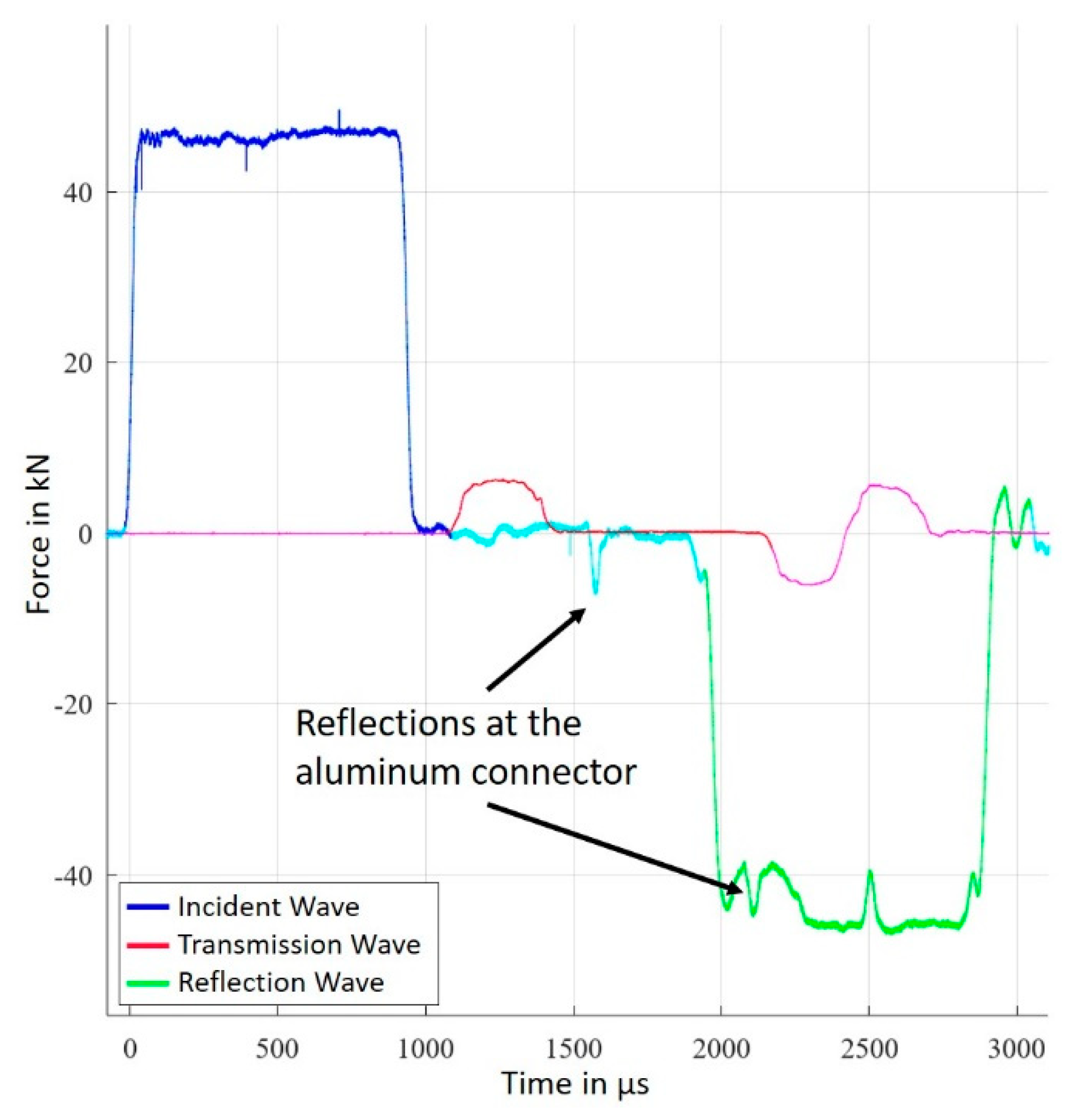
  • An air pressure launch system: 2.3 bar, which leads to a 13 m/s striker velocity and an incident pulse of 48 kN with a duration time of around 1 ms (see Figure 4);
  • A piece of paper between the flange and striker as a pulse shaper;
  • Strain gauges to measure the force, and DIC to evaluate the displacement;
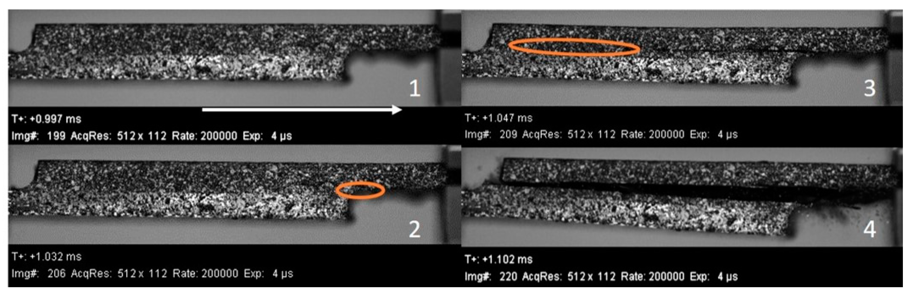
  • A high-speed camera for the DIC (Phantom v1610, 200,000 fps and 512 × 112 pixel).
Figure 3 shows the aluminum connector that connected the two incident bars. This aluminum connector induced reflections of the incident wave as well as small disturbances in the back reflection signals at strain gauges one and two (see Figure 3: Lagrange diagram). Figure 4 shows the incident, transmission, and reflected waves of the multi-material bolted experiment, BT-M05. It can be seen that the reflections from the connector did, however, affect the reflected wave, as seen by the spikes in Figure 4, but the reflections at the aluminum connector did not affect the specimen loading itself (transmission wave of BT-M05). The aluminum connector was necessary to allow for the long input bar required for long test times. Different materials and geometry combinations were tried out, and the aluminum connector shown was the best-performing of all variations.
A split Hopkinson tension bar (SHTB) requires some kind of mounting device. Often, an external thread is used to keep the specimen in position during the experiment [29,30]. Different mounting methods have been used for an SHTB, but most investigations conducted experiments with symmetric flat specimens which consisted of one material only [30,31,32,33,34]. It is important that all mounting devices enable the transfer of high loads to the specimens and do not disturb the elastic waves. A disturbance of such elastic waves happens when the impedance changes. The impedance of a structure depends on the cross-sectional area (A), the density (ρ), and the sound velocity (c) of the material, which leads to Equation (1) [34]:
zi = Aii*ci
Following the investigation of Ganzenmüller et al. [34], a constant impedance mounting device was developed to minimize such impedance changes. This device was made of the same material and diameter as the bars (titanium), and it was designed with a constant cross-sectional area from the beginning of the interface between the bars and the device to the end of the mounting device. The transition from round bars to rectangular sections was performed by interpolating through with 10 super-ellipses, as described by Ledford et al. [35]. Figure 5 shows the used mounting device after an experiment, as well as a technical drawing. Figure 5a shows the aluminum part fastened into the device and Figure 5b shows the CFRP part of a bonded/bolted joint. The specimen was held in place using four titanium bolts. These bolts clamped the ends of the mounting device together. Each bolt was torqued with 12 Nm, which was controlled with a torque wrench. To increase the friction force between the specimen and the mounting device, a silicon carbide powder was sprinkled on the ends of the substrates that were inserted in the grips. Figure 5c shows the device mounted into the SHTB. Each mounting device featured a notch in which the specimen was placed. It should be noted that this notch was not symmetrical inside the mounting device. In fact, it featured an offset to enable the alignment of each side of the single-lap specimen with the bars. Using this strategy, two of the same grips could be used by simply rotating one of them by an angle of 180° around the axis of the bar. With this technique, no additional spacers were necessary to avoid the bending of the specimen at the beginning of the experiments.

2.2.3. Data Analysis

Figure 6 shows the tracked points that were used to calculate the displacement for the specimen. The reported value was the magnitude of the vector between the two points. This displacement calculation included any bending in the specimen that occurred during the experiments. The points were located outside of the overlap area of the specimen to exclude any influence of the adhesive or bolt on the displacement measurements. A linear interpolation between the force measurement and the DIC data was performed to match the values in time. The energy absorption for each joint was calculated as the integral of the force–displacement curve up to the last point, where 400 N of force was transmitted. This was chosen as a lower cutoff to feature a consistent end to the data. This point was also taken as the maximum displacement for the joints.
Force equilibrium is one requirement for a valid high-rate experiment using an SHTB. This is an additional challenge when testing single-lap joints with an SHTB, compared to the relatively small flat specimens that are typically tested using an SHTB. At the beginning of an SHTB experiment, the specimen is stationary. When the incident wave reaches the specimen, one end of the specimen is accelerated, resulting in a load only at this end. When the incident wave reaches the other end of the specimen, a part of the wave propagates into the transmission bar, and another part is reflected and propagates through the specimen again. After multiple reflections inside the specimen, the loads on both sides of the specimen equilibrate, and force equilibrium can be assumed [30]. Usually, a load difference of about 5% on both sides of the specimen is enough to assume force equilibrium [36]. It is commonly assumed that 5 to 20 reflections inside the specimen are required to reach force equilibrium. The required time to reach force equilibrium can be estimated using Equation (2):
treflection = (n*ls)/cs
In Equation (2), n is the number of reflections, ls is the length, and cs is the wave speed of the specimen [30]. Here, the number of reflections was assumed to be n = 5. With the individual sound velocities of the materials (CFRP = 3070 m/s, aluminum = 6320 m/s, adhesive = 1428 m/s), the effective sound velocity of the joint was estimated to be in the range of 4500 m/s. The sound velocity of the adhesive was estimated based on Young’s modulus, the density, and Poisson’s ratio of Betamte 1496 V. In the end, the time until force equilibrium was estimated to be in the range of 50 µs. The vertical black lines in Figure 7 show the moment when force equilibrium was achieved for the typical high-rate experiments on bolted, bonded, and bonded/bolted (from left to right) experiments carried out using a split Hopkinson bar. In all cases, the equilibrium was reached during the initial slope, thus giving a high level of confidence in the recorded force–time data.

3. Results and Discussion

In the following sections, the results of the quasi-static and high-rate experiments are presented and discussed. The presented results consist of the unfiltered force–displacement curves, the failure sequences of the individual joints, and images of the failed specimens.

3.1. Multi-Material Bolted Joints

3.1.1. Phenomenology

Figure 8 shows the typical failure sequence observed during the high-rate loading of bolted joints. The aluminum substrate is shown on the top and the CFRP substrate is shown on the bottom. The numbers of the different pictures correspond to the marked time steps in Figure 7a. The loading velocity for this example was 11.2 m/s and was taken from the slope of the displacement–time curve after the force equilibrium. The white arrow in picture 1 (Figure 8) indicates the loading direction of the SHTB. This frame was recorded at the onset of the force plateau seen in Figure 7a. Here, the bending of the two substrates can be seen, leading to gaps forming at the free ends of the overlap region. At this moment no cracks, delamination, or fractures were noticed. After this first marked moment, the bending of the aluminum substrate increased significantly more than that of the CFRP. At the second marked moment, the first delamination occurred in the middle of the CFRP. This area is marked with the orange-colored oval. Despite the CFRP starting to fail, the bolted joint still transferred the plateau load level for an additional 50 µs. Subsequently, the CFRP delaminated at several interfaces, as seen in the third marked image. When this occurred, the bending of the aluminum substrate continued and the bolt was pulled deeper through the countersunk bolt hole on the CFRP side. The failure mode of the bolted joints was a complex combination of net tension, shear-out, and combined tension and shear-out failure.

3.1.2. Assessment of Rate Effects and Failure Modes

Figure 9 shows the unfiltered force–displacement curves for all quasi-static and high-rate multi-material bolted-joint experiments. The general trend of the force–displacement curves consisted of a steep rise and a plateau phase, followed by a steep fall. During the plateau phase, the force of the high-rate experiments oscillated with amplitudes that were smaller than 0.5 kN, which corresponded to approximately 8% of the maximum force. A rate effect was observed, as high-rate experiments showed a larger maximum force and displacement, and thus, a larger energy absorption than quasi-static experiments. On average, the maximum quasi-static force was 5.77 kN and the maximum high-rate force was 6.39 kN, which was an increase of approximately 10.7%. On average, the energy absorption for the quasi-static experiments was 12.15 J, while the average value of the absorbed energy for the high-rate experiments was 19.66 J, which corresponded to an increase of approximately 61.8%. The end of the domain that was considered to compute the energy absorption (a force below 400 N) is marked by black points in Figure 7a. Table 1 summarizes the recorded maximum forces, displacements, energy absorptions, loading rates, and failure modes for the bolted-joint experiments.
Figure 10 shows photographs of the bolted-joint specimens after testing. The images of BT-M01 and BT-M02 show the bolt head, which was pulled beneath some layers of the CFRP. Due to the countersunk bolt head and the bending of the substrate, the bolt cut into the CFRP layers, which were beneath the top layer of the composite. Therefore, the CFRP delaminated at all ply interfaces, and the bolt induced different failure modes for every failed ply. The aluminum substrate was plastically bent at all test speeds. BT-M03 was the specimen in which a bolt shear failure occurred. Therefore, the force–displacement curve in Figure 9 fell suddenly to zero at a force of 5.78 kN and a displacement of 1.61 mm. A bolt shear failure was only seen in the quasi-static experiments and indicated a rate dependency of the titanium bolt. The observed rate dependency of titanium is also supported by the literature [37].
Due to the different mechanical behavior and failure modes seen with the quasi-static and high-rate experiments, it was clear that the behavior of the bolted joints depended on the loading rate. Seidt et al. [14] investigated Al2024 and showed that the tensile mechanical behavior of this kind of aluminum was not dependent on the loading rate. Therefore, the difference in mechanical behavior was strongly influenced by the CFRP. This highlights the need to realize quasi-static and high-rate tests at the level of the joints. The silicon carbide powder—visible on the ends of the specimens—did not disturb the measurements because it was only on the ends of the specimens, which were mounted into the mounting device. This carbide powder was used to increase the friction between the specimen and the mounting device, and thus the transmitted force was increased.

3.2. Multi-Material Bonded Joints

3.2.1. Phenomenology

Figure 11 shows the typical failure sequence observed during high-rate loading of multi-material bonded joints. The CFRP substrate is shown on the top and the aluminum substrate is shown on the bottom. The numbers of the different pictures correspond to the marked time steps in Figure 7b. Unlike for the bolted joint, the velocity profile was not constant. At first, there was an acceleration phase that ended just before the time that force equilibrium was achieved. After this, the displacement-over-time rate stayed constant and was measured as 2.75 m/s. The loading rate of the multi-material bonded joints was lower than for the multi-material bolted joints due to the higher strength and stiffness of the bonded joints. This was a consequence of the open-loop nature of split Hopkinson testing, in which the loading rate depends on the specimen, even given the same applied tensile wave as described in Section 2.2.2. The loading rate was taken as the slope of the displacement–time curve, shown in Figure 7b, after the force equilibrium.
Picture 3 of Figure 11 shows the moment just before the delamination in the CFRP substrate spread over the whole overlap length. Inside the area of the orange-colored oval, the CFRP was still bonded. Picture 4 of Figure 11 shows the failed specimen in delamination mode. Similar observations regarding delamination failure in joints with composite substrates have been made by other researchers [38,39,40]. This was due to the fact that the interlaminar properties of the composite were lower than the strength of the adhesive used for this research. Compared to the bolted joints, the bending of the substrates was smaller.

3.2.2. Assessment of Rate Effects and Failure Modes

Figure 12 shows the unfiltered force–displacement curves of the quasi-static and high-rate bonded joints. The trend of the force–displacement curves consisted of a steep increase up to the maximum force; after that, the force dropped to zero. A rate effect was also observed here, as the high-rate experiments showed a larger maximum force than the quasi-static experiments. On average, the maximum quasi-static force was 9.48 kN; the maximum high-rate force was 13.26 kN, which was an increase of approximately 39.8%. On average, the energy absorption for the quasi-static experiments was 0.77 J, while the energy absorption for the high-rate experiments was 1.52 J, which was an increase of approximately 97.4%. Due to the lower frame rate of the camera used for the quasi-static experiments (f = 0.2 Hz), the datasets after the maximum force were not comparable for the two different rates. Therefore, the energy absorption was only calculated up to the point of maximum force. Other investigations measured a decrease in the energy absorption at higher loading rates [26,27,28]. Nevertheless, for this substrate material and adhesive combination, an increase in the energy absorption at a higher loading rate was measured. This shows the need for high-quality high-rate tests. Another material–adhesive combination could lead to a different result. Table 2 summarizes the recorded maximum forces, maximum displacements, energy absorptions, loading rates, and failure modes for the bonded-joint experiments.
Figure 13 shows photographs of the bonded-joint specimens after testing. The failure mode and the trend of the force–displacement curve until the maximum force were very similar between these two loading rates, and suggested a notable increase as expected for this adhesive. This has also been shown by May et al. [16]. The adhesive used for the experiment, Betamate 1496 V, was blue and could be seen on the edges of the overlap area. Figure 13 shows that the CFRP fibers were still attached to the aluminum substrate. This shows that the adhesive was stronger in both load cases than the CFRP. The fact that the bonded specimens failed in a similar manner at both experimental loading rates tends to highlight a rate-dependent effect in the composite material properties, which has also been repeatedly reported and summarized in review articles [41,42,43]. However, a specific layer in which the delamination failure occurred could not be identified. In Figure 13, different fiber directions are marked on both parts of the failed specimens. For example, on BT-B01 and BT-B04, some fibers that featured an orientation of 45° remained bonded on the aluminum, and the fibers with an orientation of 0° remained on the CFRP substrate. However, for the specimen BT-B05, the fibers with an orientation of 0° could be seen on both sides of the failed specimen. Therefore, there were not enough data here to determine whether the failure was interlaminar or intralaminar.

3.3. Multi-Material Bonded/Bolted Joints

3.3.1. Phenomenology

Figure 14 shows the typical failure sequence observed during the high-rate loading of multi-material bonded/bolted joints. The aluminum substrate is shown on the top and the CFRP substrate is shown on the bottom. The numbers of the different pictures correspond to the marked time steps in Figure 7c. Unlike for the bolted joint, the velocity profile was not constant (see Figure 7c). All the tested bonded/bolted joints showed two distinct regions: one where the bonded joint dominated, followed by a bolted-dominated region. In the bonded-dominated region, the loading rate was around 3 m/s, and in the bolted-dominated region it was around 11.4 m/s. The loading rates were slightly higher than, but comparable to the individual joining methods. This response was consistent across all the bonded/bolted joints, as seen in Table 3.
The marked time steps from Figure 7c show the failure process of the bonded/bolted joints in Figure 14. Picture 1 of Figure 14 was taken just before the first maximum force, and shows the beginning of the delamination (orange-colored oval) in the CFRP. The delamination propagated towards the bolt (picture 2). After reaching the bolt, the CFRP delaminated suddenly along the whole overlap length. Similar to the multi-material bonded joints, it was seen that the bending of the substrate was relatively small in this phase. After the first failure, the substrates started to bend more and more, which was comparable to the behavior of the multi-material bolted joints. Due to this bending, the bolt became more tilted and was pulled through the bolt hole.

3.3.2. Assessment of Rate Effects and Failure Modes

Figure 15 shows the unfiltered force–displacement curves of the quasi-static and high-rate multi-material bonded/bolted joints. The trends between the quasi-static and high-rate experiments of the force–displacement curves were similar. The force–displacement response of the bonded/bolted joints showed two distinct regions: one where the bonded joint dominated, followed by a bolted-dominated region. Due to the sudden release of energy occurring with the brittle delamination failure of the CFRP, additional oscillations were observed during the further loading of the specimen for the high-rate experiments between 0.5 mm and 1.5 mm, as seen in Figure 15. It was noted that these oscillations originated in the tested object and were not caused by the testing equipment of the SHTB. The reason for the observed post-CFRP-failure oscillations was the difference in the impedance between the specimen and the mounting devices, which led to stress wave reflections into the specimen. The only way to avoid this would be to make the substrates as long as the SHTB, which would be completely impractical.
A rate effect was observed, as the high-rate experiments showed a larger global maximum force and global displacement than the quasi-static experiments. On average, the maximum quasi-static force was 8.91 kN and the maximum high-rate force was 14.22 kN, which was an increase of approximately 60%. On average, the energy absorption for the quasi-static experiments was 12.74 J, while the energy absorption of the high-rate experiments was 18.88 J, which was an increase of approximately 48%. Table 3 summarizes the recorded maximum forces, maximum displacements, energy absorptions, loading rates, and failure modes for the multi-material bonded/bolted joints. The bonded/bolted joints were, in this case, a good superposition of the two joining methods, even though it has been shown that this is not necessarily the case [11].
Figure 16 shows photographs of the bonded/bolted-joint specimens after testing. For the high-rate experiments, it could be seen that the failure modes of the bonded/bolted joints were a combination of the bonded-only and bolted-only joints. In a similar manner as in the case of the bonded joints, the CFRP layers remained on the aluminum substrate, which was induced by the delamination of the CFRP. Also, layers with a different fiber direction could be seen on the aluminum. Additionally, no specific layer could be identified in which the CFRP delaminated. Furthermore, as with the bolted-only joints, the aluminum was plastically deformed and therefore permanently bent after the experiments. For the quasi-static specimen BT-H02, bolt failure occurred at a force of 6 kN and a displacement of 1.98 mm. As mentioned above for the bolted-only joints, only the quasi-static specimens observed bolt failure and showed a rate dependency for the titanium bolt. The observed rate dependency of the titanium was also supported by the literature [37].
BT-H01 also showed a different failure behavior. It showed two maximums at the bonded-dominated region of the force–displacement curves (see Figure 15). At the beginning, this specimen reached a maximum of 7.39 kN at a displacement of around 0.1 mm. After this maximum, the force dropped down to around 5.9 kN and rose again to a second maximum. It could be observed on the recorded images of the test that the CFRP did not fail over the hole overlap length after this first maximum. The first sudden failure occurred between the free end of the aluminum and the edge of the bolt. It seemed that the clamping force of the bolt and the load-sharing between the bolt and the bond line were strong enough to stop the failure process. A more detailed description of the failure process was not possible, because no cracks or damages were seen in the captured pictures until the first sudden failure. Therefore, in this case, the bonded part of the specimen BT-H01 completely failed after the second maximum. This failure behavior only occurred for the quasi-static-tested bonded/bolted joints.
In conclusion, the multi-material bonded/bolted joint’s force–displacement response and failure modes occurred in a sequential manner, where the bond line took the load initially, and after the delamination failure of the CFRP (similar to that of the bonded-only joint), the bolt continued to carry a lower load level until it was pulled out of the substrates (in a similar manner as that of the bolted-only joint).

3.4. Joint Type Comparison

Figure 17 shows the unfiltered force–displacement curves of one representative of every kind of joint and loading rate. For the joints tested at high rates, one representative curve was selected for each type of specimen, while for the joints tested under quasi-static loading conditions, average curves over all the repetitions of each specimen type are presented. Here, the mentioned two distinct regions of the bonded/bolted joints can be clearly identified. The first one is where the bonded joint dominates, and this is followed by the second bolted-joint-dominated region. However, the maximum force of the bonded/bolted joints in the second region was slightly lower in its respective loading rate compared to the bolted joints. As mentioned above, the CFRP failed through delamination after the global maximum. Therefore, the CFRP was pre-damaged when the bolt carried the load, and the bonded/bolted joints did not reach the same maximum load levels as the purely bolted joints. Figure 17 also shows the sudden delamination failure of the bonded/bolted joints at the global maximum force. The oscillations measured in the high-rate bonded/bolted joint were part of the joint response. A comparison of the level of oscillations caused by the testing setup (seen in the pink lines for the bolted-joint response) and those caused by the partial failure of the specimen during the test (seen in the blue lines of the bonded/bolted joint) gives a good impression of how clean the measured force signals were.
Table 5 shows the average values for the maximum force and energy absorption of the different kinds of joints. By comparing the different quasi-static experiments, it can be seen that the bonded joints reached the highest average maximum force, at 9.48 kN. It was expected that the bonded/bolted joints would reach the highest average force due to the load-sharing between the bolt and bond line. In bonded/bolted joints, there was a trade-off between load-sharing and removing the bonded surface for the bolt hole. However, the experiments show that the adhesive was not the weakness for the tested joint. Here, the CFRP failed through delamination for every bonded specimen. Nevertheless, the quasi-static bonded/bolted joints reached the highest average energy absorption compared to the other joints tested under quasi-static loading conditions, with an energy absorption of 12.74 J.
By comparing the responses of the different high-rate experiments, it can be seen that the multi-material bonded/bolted joints reached the highest average maximum force, with a value of 14.22 kN. There were potential differences observed between the bonded/bolted specimens and the bonded ones, such as a slightly higher global maximum load in the bonded section, but more specimens would be required to determine if the difference is statistically significant. The highest average energy absorption was seen with the multi-material bolted joints, at 19.66 J. The damages to the CFRP of the multi-material bonded/bolted joints after the first global maximum induced a lower force plateau compared to the multi-material bolted joints. Nevertheless, all the joints showed a strain rate dependency for both the maximum force and the absorbed energy. This can be expressed in terms of dynamic increase (DI), which is the ratio of the considered value at a high rate of loading divided by the value at quasi-static loading conditions. The results of the dynamic increase are listed in Table 4.
From the results of Table 5, it can be seen that the bonded/bolted joint does appear to be nearly a linear superposition of the two different joining methods. The maximum force of the bonded and bonded/bolted joints were similar, as was also the case for the energy absorbed by the bolted and bonded/bolted joints. This does not show any synergy from combining the different methods, which has been shown to be possible [15]; however, this result is not unexpected, as suggested by Kelly [44]. Here, the joint had a stiff adhesive and a brittle first failure seen in the composite. Nevertheless, it does show that combining the two joining methods does allow the joint to have both the high strength and stiffness of an adhesive joint and the high energy absorption of a bolted joint.
With the high-quality results shown in this work, the split Hopkinson tension bar appears to be an appropriate type of testing equipment for characterizing joints at high loading rates. An SHTB can be used to measure the differences in the maximum force and energy absorption at crash-relevant speeds without filtering the data and with limited oscillations.

4. Conclusions

Three different representative aerospace joints were investigated at low and high loading rates using a split Hopkinson tension bar (SHTB). The conclusions that can be drawn from this study fall into two categories: those about the testing method itself, and those about the tested multi-material bolted, bonded, and bonded/bolted joints.
Regarding the evaluation of the test method, it was demonstrated that it was possible to expand an SHTB specimen from a simple, small, homogenous specimen to larger, complex, multi-material joint. The SHTB technique was able to record high-quality force data on a realistic size and strength specimen, which allowed for a detailed analysis of the loading rate sensitivity without the ambiguity that might be caused by oscillations or filtering models. Additionally, it was shown that asymmetric single-lap joint specimens can be successfully tested with our newly designed mounting device.
Regarding the evaluation of the joint response, all different types of joints showed a rate dependency for both the maximum force and the absorbed energy. This corresponded to the following dynamic increases, which were the ratios of the considered values at a high rate of loading divided by the values at quasi-static loading conditions:
  • Bolted dynamic increase: force DI = 1.11; energy absorbed DI = 1.62;
  • Bonded dynamic increase: force DI = 1.4; energy absorbed DI = 5.12;
  • Bonded/Bolted dynamic increase: force DI = 1.6; energy absorbed DI = 1.48.
Furthermore, the mechanical behavior of the bonded/bolted joints could be well approximated by the superposition of the behavior of the two separate joint types. The loading-rate effects of the bonded/bolted joint were consistent with the understanding of the individual joint types, showing that high-strength and high-stiffness joints can be combined to create a large energy-absorption joint. Across all the different kinds of specimens, joint failure was dominated by the composite response, where the delamination of the CFRP was the initial failure. Additionally, the titanium fastener also showed a rate dependency. Some bolts failed in shear under quasi-static loading conditions, which was not observed at the high-rate loading conditions.
Based on the novel experimental procedure presented in this work, future research should investigate ways of optimizing multi-material joints.

Supplementary Materials

The following supporting information can be downloaded at: https://www.mdpi.com/article/10.3390/met12071082/s1: Video S1: Failure sequence of the multi-material bolted joint BT-M05; Video S2: Failure sequence of the multi-material bonded joint BT-B05; Video S3: Failure sequence of the multi-material bonded/bolted joint BT-H09.

Author Contributions

Conceptualization, M.M.; software, P.R. and N.L.; investigation, P.R.; resources, N.L. and M.M.; writing—original draft preparation, P.R.; writing—review and editing, N.L., M.I. and M.M.; visualization, P.R.; supervision, M.M.; project administration, M.I. All authors have read and agreed to the published version of the manuscript.

Funding

The funding for this research from the German Ministry of Defence (BMVg) is gratefully acknowledged.

Data Availability Statement

Not applicable.

Acknowledgments

The authors would like to thank Martin Blacha (Airbus Helicopters), Mircea Calomfirescu (Airbus Defence and Space), Sebastian Heimbs (Airbus Operations), and Jens Holtmannspötter (BAAINBw) for their fruitful discussions.

Conflicts of Interest

The authors declare no conflict of interest.

References

  1. May, M. Rate-Dependent Material Properties of Adhesively Bonded Joints—Must Have or Nice to Have? Key Eng. Mater. 2020, 858, 14–19. [Google Scholar] [CrossRef]
  2. Egan, B.; McCarthy, C.T.; McCarthy, M.A.; Gray, P.J.; O’Higgins, R.M. Static and high-rate loading of single and multi-bolt carbon–epoxy aircraft fuselage joints. Compos. Part A Appl. Sci. Manuf. 2013, 53, 97–108. [Google Scholar] [CrossRef] [Green Version]
  3. Shamaei-Kashani, A.R.; Shokrieh, M.M. Strain rate effects on the mechanical behavior of single-lap glass/carbon nanofiber/epoxy composite bolted joints. J. Compos. Mater. 2020, 54, 4807–4819. [Google Scholar] [CrossRef]
  4. Pearce, G.M.; Johnson, A.F.; Thomson, R.S.; Kelly, D.W. Experimental Investigation of Dynamically Loaded Bolted Joints in Carbon Fibre Composite Structures. Appl. Compos. Mater. 2010, 17, 271–291. [Google Scholar] [CrossRef]
  5. Murakami, S.; Sekiguchi, Y.; Sato, C.; Yokoi, E.; Furusawa, T. Strength of cylindrical butt joints bonded with epoxy adhesives under combined static or high-rate loading. Int. J. Adhes. Adhes. 2016, 67, 86–93. [Google Scholar] [CrossRef]
  6. Paul, H.; Ledford, N.; Sauer, M.; May, M.; Okamura, M. Assessment of test methods for thick and thin layer adhesive joints under high rates of loading. Int. J. Adhes. Adhes. 2018, 83, 123–129. [Google Scholar] [CrossRef]
  7. Essersi, O.; Tarfaoui, M.; Boyd, S.; Shenoi, R.A.; Meraghni, F. Experimental study of dynamic behaviour of Aluminum/Aluminum and Composite/Composite double lap joints. Appl. Mech. Mater. 2011, 62, 155–163. [Google Scholar] [CrossRef]
  8. Yao, M.; Zhu, D.; Yao, Y.; Zhang, H.; Mobasher, B. Experimental study on basalt FRP/steel single-lap joints under different loading rates and temperatures. Compos. Struct. 2016, 145, 68–79. [Google Scholar] [CrossRef]
  9. May, M.; Hesebeck, O. Assessment of experimental methods for calibrating rate-dependent cohesive zone models for predicting failure in adhesively bonded metallic structures. Eng. Fail. Anal. 2015, 56, 441–453. [Google Scholar] [CrossRef]
  10. Bodjona, K.; Lessard, L. Hybrid bonded-fastened joints and their application in composite structures: A general review. J. Reinf. Plast. Compos. 2016, 35, 764–781. [Google Scholar] [CrossRef]
  11. Ledford, N.; Paul, H.; Isakov, M.; Hiermaier, S. High rate loading of hybrid joints in a Split Hopkinson Tension Bar. In Proceedings of the DYMAT 2018—12th International Conference on the Mechanical and Physical Behaviour of Materials under Dynamic Loading, Arcachon, France, 9–14 September 2018. [Google Scholar]
  12. Di Franco, G.; Zuccarello, B. Analysis and optimization of hybrid double lap aluminum-GFRP joints. Compos. Struct. 2014, 116, 682–693. [Google Scholar] [CrossRef] [Green Version]
  13. Graham, D.P.; Rezai, A.; Baker, D.; Smith, P.A.; Watts, J.F. The development and scalability of a high strength, damage tolerant, hybrid joining scheme for composite–metal structures. Compos. Part A Appl. Sci. Manuf. 2014, 64, 11–24. [Google Scholar] [CrossRef] [Green Version]
  14. Gonzales, D.S. Mechanical Behavior of Metal-Composite Joints. Master’s Thesis, Michigan State University, East Lansing, MI, USA, 2014. [Google Scholar]
  15. Seidt, J.D.; Gilat, A. Plastic deformation of 2024-T351 aluminum plate over a wide range of loading conditions. Int. J. Solids Struct. 2013, 50, 1781–1790. [Google Scholar] [CrossRef]
  16. Heimbs, S.; Schmeer, S.; Blaurock, J.; Steeger, S. Static and dynamic failure behaviour of bolted joints in carbon fibre composites. Compos. Part A Appl. Sci. Manuf. 2013, 47, 91–101. [Google Scholar] [CrossRef]
  17. May, M.; Hesebeck, O.; Marzi, S.; Wolfgang, B.; Lienhard, J.; Kilchert, S.; Brede, M.; Hiermaier, S. Rate dependent behaviour of crash-optimized adhesives—Experimental characterization, model development, and simulation. Eng. Fract. Mech. 2015, 133, 112–137. [Google Scholar] [CrossRef]
  18. Porcaro, R.; Langseth, M.; Hanssen, A.G.; Zhao, H.; Weyer, S.; Hooputra, H. Crashworthiness of self-piercing riveted connections. Int. J. Impact Eng. 2008, 35, 1251–1266. [Google Scholar] [CrossRef]
  19. Ledford, N.; May, M. Modeling of multimaterial hybrid joints under high-rate loading. J. Process Mech. Eng. 2020, 234, 1–8. [Google Scholar] [CrossRef]
  20. Daimaruya, M.; Fujiki, H.; Ambarita, H.; Kobayashi, H.; Shin, H.-S. Shear fracture of jointed steel plates of bolted joints under impact load. J. Phys. Conf. Ser. 2013, 451, 012007. [Google Scholar] [CrossRef] [Green Version]
  21. Venkadachalam, A. Experimental & Numerical Study of Dynamically Loaded Bolted & Hybrid (Bolted/Bonded) Joints. Master’s Thesis, Engineering Mechanics, Michigan State University, East Lansing, MI, USA, 2014. [Google Scholar]
  22. VanderKlok, A.; Dutta, A.; Tekalur, S.A. Metal to composite bolted joint behavior evaluated at impact rates of loading. Compos. Struct. 2013, 106, 446–452. [Google Scholar] [CrossRef]
  23. Yokoyama, T. Experimental determination of impact tensile properties of adhesive butt joints with the split Hopkinson bar. J. Strain Anal. Eng. Des. 2003, 38, 233–245. [Google Scholar] [CrossRef]
  24. Goda, Y.; Sawa, T. Study on the Effect of Strain Rate of Adhesive Material on the Stress State in Adhesive Joints. J. Adhes. 2011, 87, 766–779. [Google Scholar] [CrossRef]
  25. Zhao, H.; Duan, X.; Ma, M.; Lu, L.; Cai, Z.; Wang, P.; Fickes, J. Dynamic characteristics of adhesive bonded high strength steel joints. Sci. Technol. Weld. Join. 2010, 15, 486–490. [Google Scholar] [CrossRef]
  26. Lißner, M.; Alabort, E.; Cui, H.; Rito, R.; Blackman, B.; Petrinic, N. Experimental characterisation and numerical modelling of the influence of bondline thickness, loading rate, and deformation mode on the response of ductile adhesive interfaces. J. Mech. Phys. Solids 2019, 130, 349–369. [Google Scholar] [CrossRef]
  27. Lißner, M.; Erice, B.; Alabort, E.; Thomson, D.; Cui, H.; Kaboglu, H.; Blackman, B.; Gude, M.; Petrinic, N. Multi-material adhesively bonded structures: Characterisation and modelling of their rate-dependent performance. Compos. Part B Eng. 2020, 195, 108077. [Google Scholar] [CrossRef]
  28. Lißner, M.; Alabort, E.; Erice, B.; Cui, H.; Blackman, B.R.; Petrinic, N. On the dynamic response of adhesively bonded structures. Int. J. Impact Eng. 2020, 138, 103479. [Google Scholar] [CrossRef]
  29. Ledford, N.; Paul, H.; Ganzenmüller, G.; May, M.; Höfemann, M.; Otto, M.; Petrinic, N. Investigations on specimen design and mounting for Split Hopkinson Tension Bar (SHTB) experiments. EPJ Web Conf. 2015, 94, 01049. [Google Scholar] [CrossRef] [Green Version]
  30. Chen, W.W.; Song, B. Split Hopkinson (Kolsky) Bar Design, Testing and Applications; Springer: New York, NY, USA, 2011. [Google Scholar]
  31. Owens, A.T.; Tippur, H.V. A Tensile Split Hopkinson Bar for Testing Particulate Polymer Composites Under Elevated Rates of Loading. Exp. Mech. 2009, 49, 799–811. [Google Scholar] [CrossRef]
  32. Huh, H.; Kang, W.J.; Han, S.S. A Tension Split Hopkinson Bar for Investigating the Dynamic Behavior of Sheet Metals. Exp. Mech. 2002, 42, 8–17. [Google Scholar] [CrossRef]
  33. Gerlach, R.; Siviour, C.R.; Wiegand, J.; Petrinic, N. In-plane and through-thickness properties, failure modes, damage and delamination in 3D woven carbon fibre composites subjected to impact loading. Compos. Sci. Technol. 2012, 72, 397–411. [Google Scholar] [CrossRef]
  34. Ganzenmüller, G.C.; Langhof, T.; Hiermaier, S. A Constant Acoustic Impedance Mount for Sheet-Type Specimens in the Tensile Split-Hopkinson Bar. EPJ Web Conf. 2018, 183, 02064. [Google Scholar] [CrossRef]
  35. Ledford, N.; Imbert, M.; May, M. High-Rate In-Plane Shear Testing of IM7/8552 Using the Split Hopkinson Tension Bar. AIAA J. 2021, 59, 4257–4263. [Google Scholar] [CrossRef]
  36. Yang, L.M.; Shim, V.P.W. An analysis of stress uniformity in split Hopkinson bar test specimens. Int. J. Impact Eng. 2005, 31, 129–150. [Google Scholar] [CrossRef]
  37. Verleysen, P.; Peirs, J. Quasi-static and high strain rate fracture behaviour of Ti6Al4V. Int. J. Impact Eng. 2017, 108, 370–388. [Google Scholar] [CrossRef]
  38. Kim, K.; Yoo, J.; Yi, Y.; Kim, C. Failure mode and strength of unidirectional composite single lap bonded joints with different bonding methods. Compos. Struct. 2006, 72, 477–485. [Google Scholar] [CrossRef]
  39. Song, M.-G.; Kweon, J.-H.; Choi, J.-H.; Byun, J.-H.; Song, M.-H.; Shin, S.-J.; Lee, T.-J. Effect of manufacturing methods on the shear strength of composite single-lap bonded joints. Compos. Struct. 2010, 92, 2194–2202. [Google Scholar] [CrossRef]
  40. Budhe, S.; Banea, M.; de Barros, S.; da Silva, L. An updated review of adhesively bonded joints in composite materials. Int. J. Adhes. Adhes. 2017, 72, 30–42. [Google Scholar] [CrossRef]
  41. Jacob, G.; Starbuck, J.; Fellers, J.; Simunovic, S.; Boeman, R. Strain Rate Effects on the Mechanical Properties of Polymer Composite Materials. J. Appl. Polym. Sci. 2004, 94, 296–301. [Google Scholar] [CrossRef]
  42. May, M. Measuring the rate-dependent mode I fracture toughness of composites—A review. Compos. Part A Appl. Sci. Manuf. 2016, 81, 1–12. [Google Scholar] [CrossRef]
  43. May, M.; Channammagari, H.; Hahn, P. High-rate mode II fracture toughness testing of polymer matrix composites—A review. Compos. Part A Appl. Sci. Manuf. 2020, 137, 106019. [Google Scholar] [CrossRef]
  44. Kelly, G. Load transfer in hybrid (bonded/bolted) composite single-lap joints. Compos. Struct. 2005, 69, 35–43. [Google Scholar] [CrossRef]
Figure 1. (a) Dimensions of a multi-material bonded/bolted specimen (all dimensions are in millimeters); (b) multi-material bolted specimen; (c) multi-material bonded specimen; and (d) multi-material bonded/bolted specimen.
Metals 12 01082 g001
Figure 2. Quasi-static experiment at different time steps of the multi-material bonded/bolted specimen, BT-H03 (overlap length 26 mm and width 18.5 mm), with marked failure modes (DF—delamination failure, SF—shear-out failure, and NF—net tension failure): (a) at the beginning of the experiment, (b) right before the delamination failure, (c) right after the delamination failure, (d) after 330 s of the experiment, (e) after 515 s of the experiment, and (f) at the end of the experiment.
Metals 12 01082 g002
Figure 3. The SHTB configuration with an idealized Lagrange diagram.
Metals 12 01082 g003
Figure 4. Incident, transmission, and reflected waves of the multi-material bolted experiment BT-M05.
Metals 12 01082 g004
Figure 5. The device after an experiment: (a) the aluminum side, (b) the CFRP side, (c) an overview of both devices mounted into the SHTB, and (d) a technical drawing of the mounting device.
Metals 12 01082 g005
Figure 6. Example of a bonded/bolted specimen (overlap length: 26 mm and height: 4.55 mm) with a speckle pattern; the tracked points are shown in yellow and the displacement reported for each specimen was the magnitude of the vector between the points.
Metals 12 01082 g006
Figure 7. Force–time recordings for the multi-material high-rate tests on (a) bolted joints, (b) bonded joints, and (c) bonded/bolted joints. The straight black line indicates the moment when force equilibrium was reached.
Metals 12 01082 g007
Figure 8. Failure sequence of the multi-material bolted joint BT-M05. (Supplementary Material Video S1).
Metals 12 01082 g008
Figure 9. Force–displacement curves of the multi-material bolted joints (QS—quasi-static and Dy—high-rate).
Metals 12 01082 g009
Figure 10. Multi-material bolted joints after testing (BF—bearing failure, SF—shear-out failure, NF—net tension failure, and SBF—bolt shear failure).
Metals 12 01082 g010
Figure 11. Failure sequence of the multi-material bonded joint BT-B05. (Supplementary Material Video S2).
Metals 12 01082 g011
Figure 12. Force–displacement curves of the multi-material bonded joints (QS—quasi-static and Dy—high-rate).
Metals 12 01082 g012
Figure 13. Multi-material bonded joints after testing.
Metals 12 01082 g013
Figure 14. Failure sequence of the multi-material bonded/bolted joint BT-H09. (Supplementary Material Video S3).
Metals 12 01082 g014
Figure 15. Force–displacement of the multi-material bonded/bolted joints (QS—quasi-static and Dy—high-rate).
Metals 12 01082 g015
Figure 16. Representative multi-material bonded/bolted joints after testing (NF—net tension failure, SF—shear-out failure, and SBF—bolt shear failure).
Metals 12 01082 g016
Figure 17. Force–displacement curves of one representative of each kind of joint (QS—quasi-static and Dy—high-rate).
Metals 12 01082 g017
Table 1. Results of the multi-material bolted joints (NF—net tension failure, SF—shear-out failure, SBF—bolt shear failure, TSF—tension and shear-out failure).
SpecimenMax
Force [kN]
Max
Displacement [mm]
Energy
Absorption [J]
Loading
Rate [m/s]
Failure Mode
BT-M015.93.9215.315 × 106SF, NF, TSF
BT-M025.644.2613.685 × 106SF, NF, TSF
BT-M035.781.617.465 × 106SBF
Average5.773.2612.155 × 106
BT-M046.573.4517.9710.8SF, NF, TSF
BT-M056.323.9918.7311.2SF, NF, TSF
BT-M066.504.5421.6311.1SF, NF, TSF
BT-M076.136.6325.5910.2SF, NF, TSF
BT-M086.463.3314.4011.1SF, NF, TSF
Average6.394.3919.6610.88
Table 2. Results of the multi-material bonded joints (DF—delamination failure).
SpecimenMax
Force [kN]
Max
Displacement [mm]
Energy
Absorption [J]
Loading
Rate [m/s]
Failure Mode
BT-B018.970.120.545 × 106DF
BT-B028.410.120.555 × 106DF
BT-B0311.060.171.225 × 106DF
Average9.480.140.775 × 106
BT-B0412.360.533.282.8DF
BT-B0514.160.734.602.75DF
Average13.260.633.942.78
Table 3. Results of the multi-material bonded/bolted joints (DF—delamination failure, SBF—bolt shear failure, NF—net tension failure, SF—shear-out failure, and TSF—tension and shear-out failure).
SpecimenMax
Force [kN]
Max
Displacement [mm]
Energy
Absorption [J]
Loading
Rate [m/s]
Failure Mode
BT-H017.393.6413.785 × 106(1) DF,
(2) SF, NF
BT-H0210.661.9810.485 × 106(1) DF,
(2) SBF
BT-H038.685.8713.965 × 106(1) DF,
(2) SF, NF
Average8.913.8312.745 × 106
BT-H0513.484.1318.66(1) 2.63,
(2) 10.7
(1) DF,
(2) SF, NF
BT-H0614.854.1419.01(1) 3.27,
(2) 11.8
(1) DF,
(2) SF, NF
BT-H0813.644.0718.26(1) 3.37,
(2) 11.8
(1) DF,
(2) SF, NF
BT-H0914.904.1519.59(1) 2.95,
(2) 11.3
(1) DF,
(2) SF, NF
Average14.224.1218.88(1) 3.05,
(2) 11.4
Table 4. Dynamic increase for every type of joint.
Force [-]Energy Absorption [-]
Bolted dynamic increase1.111.62
Bonded dynamic increase1.45.12
Bonded/Bolted dynamic increase1.61.48
Table 5. Average maximum force and energy absorption for each joint type and loading rate.
Multi-Material Joint TypeAverage Maximum
Force [kN]
Average Energy
Absorption [J]
Bolted Quasi-Static5.7712.15
Bolted High-Rate6.3919.66
Bonded Quasi-Static9.480.77
Bonded High-Rate13.263.94
Bonded/Bolted Quasi-Static8.9112.74
Bonded/Bolted High-Rate14.2218.88
Publisher’s Note: MDPI stays neutral with regard to jurisdictional claims in published maps and institutional affiliations.

