
Joining of Macroscopic 3D Steel Transition Wire Structures to Steel Sheets: Study on the Mechanical, Microstructural, and Phase Characteristics of Brazed and Glued Joints

 , ,
, ,
Abstract
:1. Introduction
2. Experimental Procedures
2.1. Materials and Methods
2.2. Characterization Techniques
2.2.1. Pull-Off Adhesion Test
2.2.2. Light Microscopy and Scanning Electron Microscopy
2.2.3. X-ray Diffractometry
3. Results and Discussions
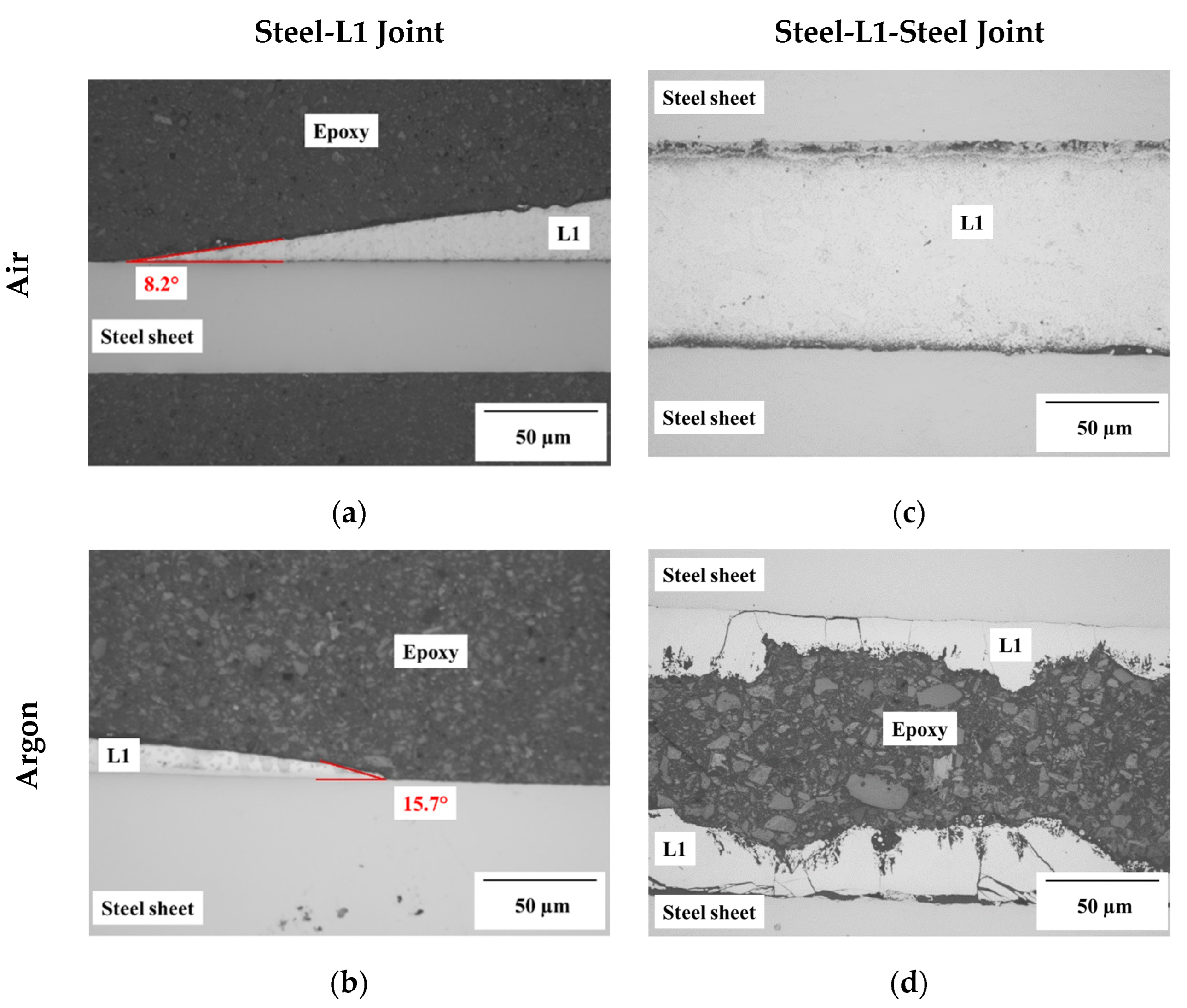
3.1. Contact Angle Analyses on L1 Joints
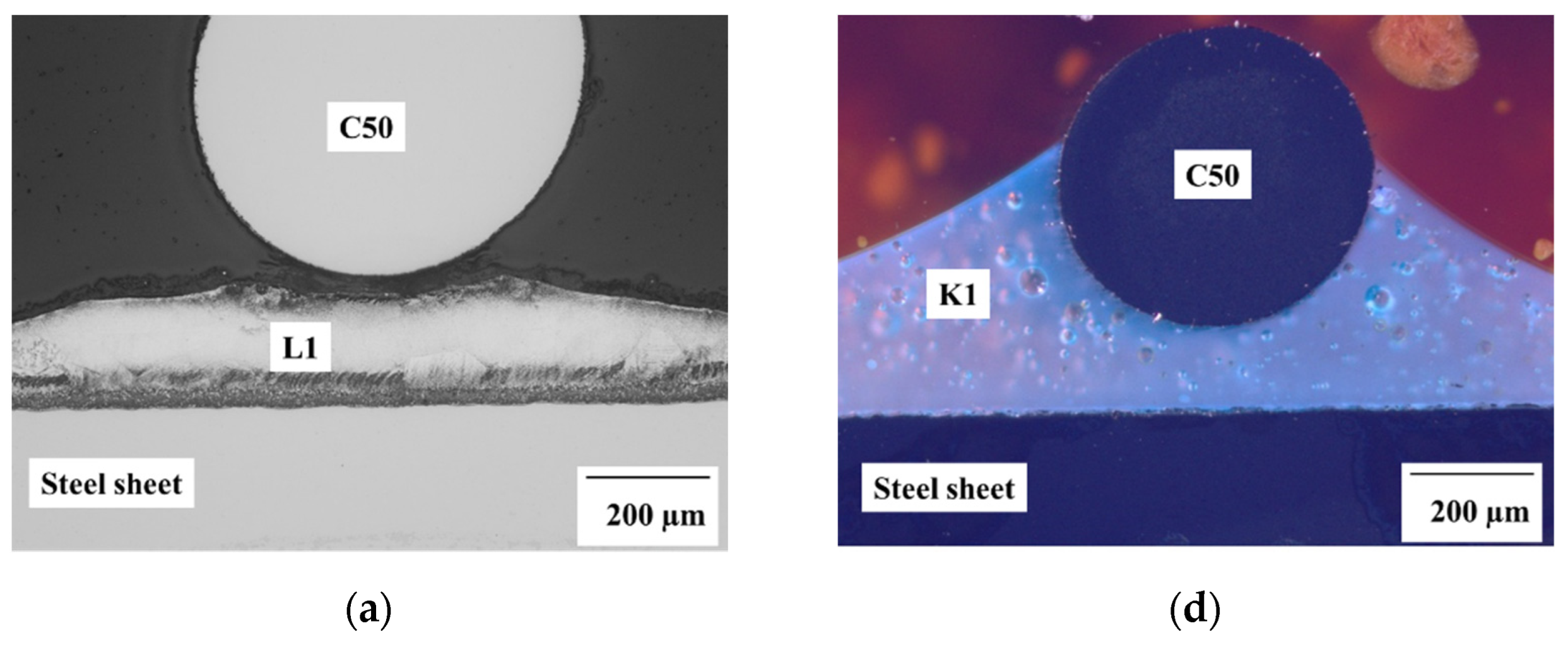
3.2. Brazing Alloy (L1) vs. Adhesive Paste (K1)
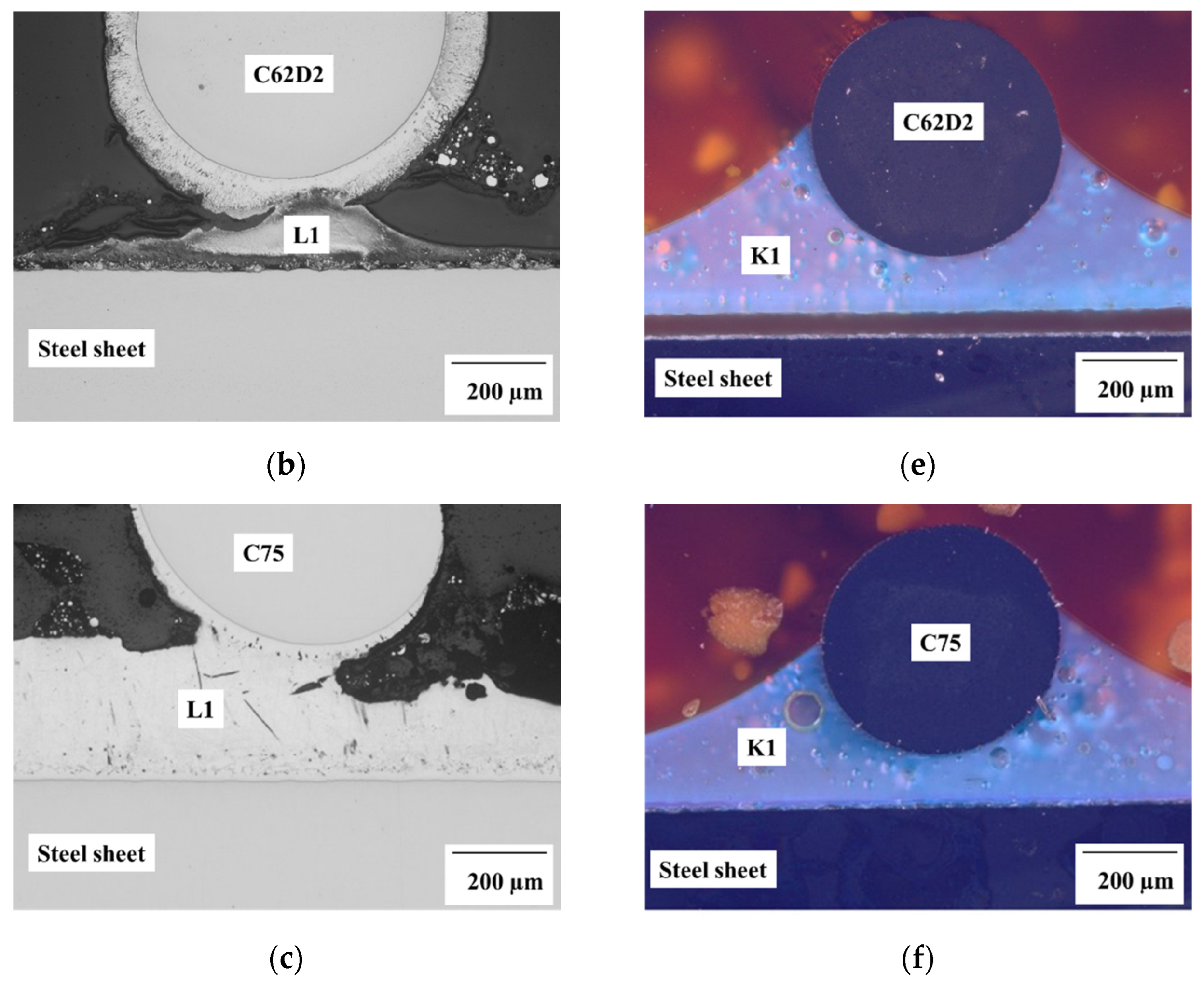
3.3. Effect of Zinc Coating on 3D-TWS
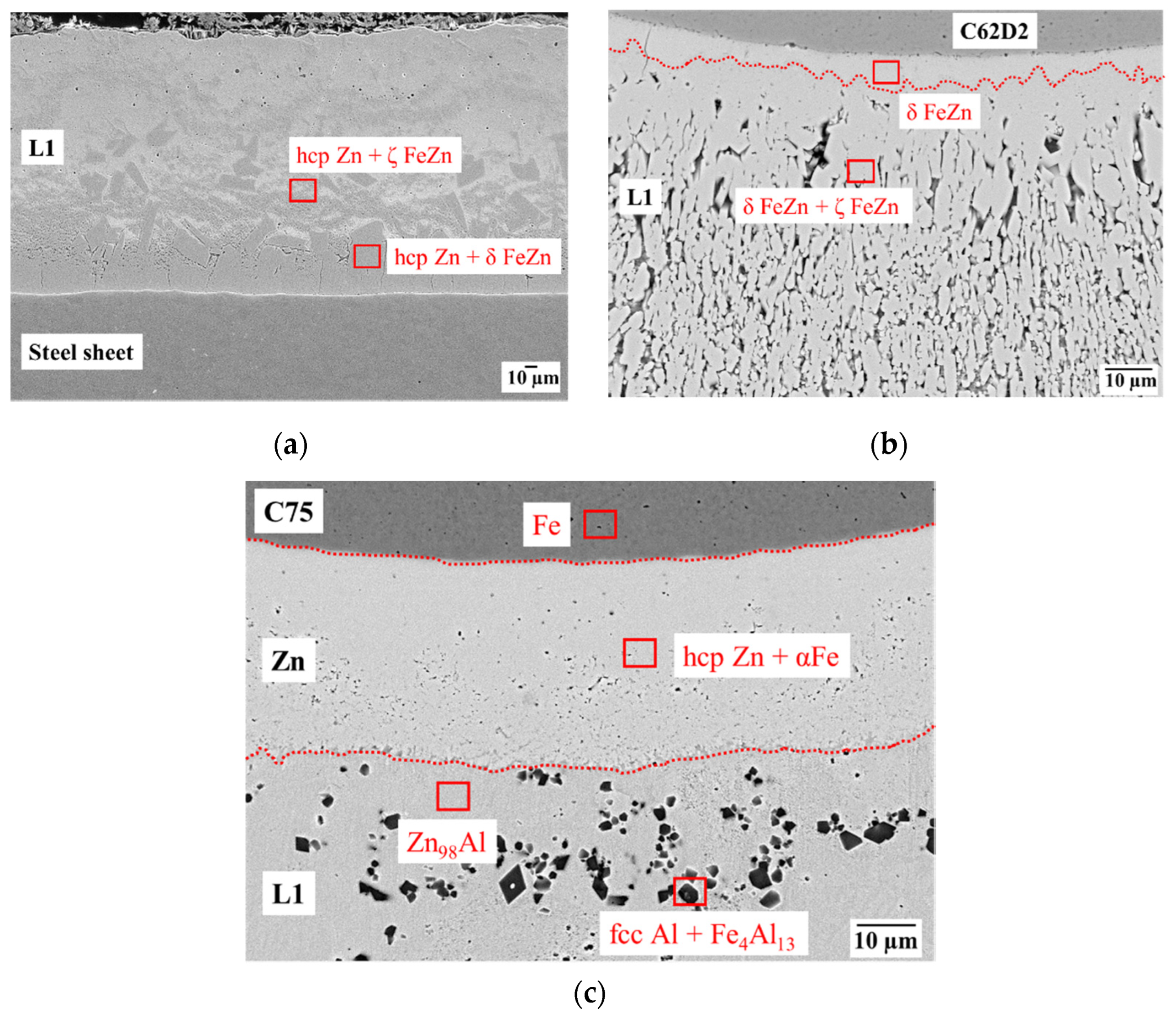
3.4. EDX Phase Analyses
4. Conclusions
Author Contributions
Funding
Institutional Review Board Statement
Informed Consent Statement
Data Availability Statement
Acknowledgments
- Husam Ahmad (Group of Composites and Material Compounds, IWW, TU Chemnitz, Germany) for the SEM and EDX phase analyses;
- Marc Pügner (Group of Materials and Surface Engineering, IWW, TU Chemnitz, Germany) for the XRD analyses;
- Anton Böttcher (Group of Composites and Material Compounds, IWW, TU Chemnitz, Germany) for the light microscopy analyses;
- Felix Schubert (Group of Materials Science, IWW, TU Chemnitz, Germany) for the pull-off adhesion test analyses;
- Christian Wesener (Group of Materials and Surface Engineering, IWW, TU Chemnitz, Germany) for the electroplating of the Zn coating on TWS.
Conflicts of Interest
References
- Kah, P.; Suoranta, R.; Martikainen, J.; Magnus, C. Techniques for joining dissimilar materials: Metals and polymers. Rev. Adv. Mater. Sci. 2014, 36, 152–164. [Google Scholar]
- Lambiase, F.; Scipioni, S.I.; Lee, C.J.; Ko, D.C.; Liu, F. A state-of-the-art review on advanced joining processes for metal-composite and metal-polymer hybrid structures. Materials 2021, 14, 1890. [Google Scholar] [CrossRef] [PubMed]
- Nestler, D.; Trautmann, M.; Zopp, C.; Tröltzsch, J.; Osiecki, T.; Nendel, S.; Wagner, G.; Kroll, L. Continuous Film Stacking and Thermoforming Process for Hybrid CFRP/aluminum Laminates. Procedia CIRP 2017, 66, 107–112. [Google Scholar] [CrossRef]
- Grujicic, M.; Sellappan, V.; Omar, M.A.; Seyr, N.; Obieglo, A.; Erdmann, M.; Holzleitner, J. An overview of the polymer-to-metal direct-adhesion hybrid technologies for load-bearing automotive components. J. Mater. Process. Technol. 2008, 197, 363–373. [Google Scholar] [CrossRef]
- Grujicic, M.; Sellappan, V.; Arakere, G.; Ochterbeck, J.M.; Seyr, N.; Obieglo, A.; Erdmann, M.; Holzleitner, J. Investigation of a polymer-metal inter-locking technology for use in load-bearing automotive components. Multidiscip. Model. Mater. Struct. 2010, 6, 23–44. [Google Scholar] [CrossRef]
- Gwon, T.M.; Kim, J.H.; Choi, G.J.; Kim, S.J. Mechanical interlocking to improve metal-polymer adhesion in polymer-based neural electrodes and its impact on device reliability. J. Mater. Sci. 2016, 51, 6897–6912. [Google Scholar] [CrossRef]
- Bula, K.; Sterzyński, T.; Piasecka, M.; Różański, L. Deformation Mechanism in Mechanically Coupled Polymer–Metal Hybrid Joints. Materials 2020, 13, 2512. [Google Scholar] [CrossRef]
- Paul, H.; Luke, M.; Henning, F. Combining mechanical interlocking, force fit and direct adhesion in polymer–metal-hybrid structures—Evaluation of the deformation and damage behavior. Compos. Part B Eng. 2015, 73, 158–165. [Google Scholar] [CrossRef]
- Lambiase, F. Influence of process parameters in mechanical clinching with extensible dies. Int. J. Adv. Manuf. Technol. 2013, 66, 2123–2131. [Google Scholar] [CrossRef]
- Lee, S.H.; Lee, C.J.; Kim, B.H.; Ahn, M.S.; Kim, B.M.; Ko, D.C. Effect of tool shape on hole clinching for CFRP with steel and aluminum alloy sheet. Key Eng. Mater. 2014, 622–623, 476–483. [Google Scholar] [CrossRef]
- Hahn, O.; Finkeldey, C. Ultrasonic Riveting and Hot-air-sticking of Fiber-reinforced Thermoplastics. J. Thermoplast. Compos. Mater. 2003, 16, 521–528. [Google Scholar] [CrossRef]
- Bula, K.; Korzeniewski, B. Polyamide 6-Aluminum Assembly Enhanced by Laser Micro structuring. Polymers 2022, 14, 288. [Google Scholar] [CrossRef] [PubMed]
- Wurzbacher, S.; Gach, S.; Reisgen, U.; Hopmann, C. Joining of plastic-metal hybrid components by over-molding of specially designed form-closure elements. Materwiss. Werksttech. 2021, 52, 367–378. [Google Scholar] [CrossRef]
- Gebauer, J.; Fischer, M.; Lasagni, A.F.; Kühnert, I.; Klotzbach, A. Laser structured surfaces for metal-plastic hybrid joined by injection molding. J. Laser Appl. 2018, 30, 032021. [Google Scholar] [CrossRef]
- Saborowski, E.; Steinert, P.; Dittes, A.; Lindner, T.; Schubert, A.; Lampke, T. Introducing fractal dimension for interlaminar shear and tensile strength assessment of mechanically interlocked polymer-metal interfaces. Materials 2020, 13, 2171. [Google Scholar] [CrossRef] [PubMed]
- Müller, S.; Brand, M.; Dröder, K.; Meiners, D. Increasing the structural integrity of hybrid plastics-metal parts by an innovative mechanical interlocking effect. Mater. Sci. Forum 2015, 825–826, 417–424. [Google Scholar] [CrossRef]
- Kleffel, T.; Drummer, D. Electrochemical treatment of metal inserts for subsequent assembly injection molding of tight electronic systems. J. Polym. Eng. 2018, 38, 675–684. [Google Scholar] [CrossRef]
- Chan, C.W.; Smith, G.C. Fibre laser joining of highly dissimilar materials: Commercially pure Ti and PET hybrid joint for medical device applications. Mater. Des. 2016, 103, 278–292. [Google Scholar] [CrossRef] [Green Version]
- Fortunato, A.; Cuccolini, G.; Ascari, A.; Orazi, L.; Campana, G.; Tani, G. Hybrid metal-plastic joining by means of laser. Int. J. Mater. Form. 2010, 3 (Suppl. S1), 1131–1134. [Google Scholar] [CrossRef]
- Cenigaonaindia, A.; Liébana, F.; Lamikiz, A.; Echegoyen, Z. Novel Strategies for Laser Joining of Polyamide and AISI 304. Phys. Procedia 2012, 39, 92–99. [Google Scholar] [CrossRef] [Green Version]
- Ridder, H.; Schnieders, J. Hybridspritzgießen—Möglichkeiten und Grenzen. In Proceedings of the Tagung Spritzgießen 2007—Oberflächen von Spritzgegossenen Teilen, Hybride Bauteile und Elektromechanik, Baden-Baden, Germany, 14–15 February 2007; VDI Verlag: Düsseldorf, Germany, 2007. [Google Scholar]


| Sample ID | Material Group | DIN/EN Number | Carbon Content | Single Wire Diameter | Permeable Cell Size |
|---|---|---|---|---|---|
| (−) | (−) | (−) | (wt.%) | (mm) | (mm) |
| C75 | Spring steel | 1.0605 | 0.70–0.80 | 0.63 | 4.7 |
| C62D2 | Spring steel | 1.1222 | 0.60–0.64 | 0.60 | |
| C50 | Tempered steel | 1.1206 | 0.50 |
| Sample ID | Material Type | Product Name | Chemical Composition | Working Temperature | Temperature Resistance | Post Curing |
|---|---|---|---|---|---|---|
| (−) | (−) | (−) | (−) | (°C) | (°C) | (−) |
| K1 | Adhesive | TOOL CRAFT—Two Component Epoxy adhesive (EPO5.K50) | Epoxy resin + Hardener | RT | ~120 | 25 °C/48 h |
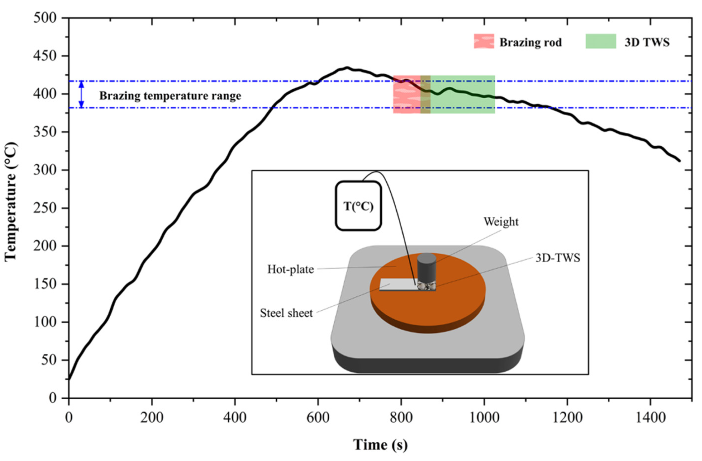
| L1 | Brazing alloy | Fontargen AF631 NH | Zn98Al solder rods with flux core | 382–417 | - | - |
Publisher’s Note: MDPI stays neutral with regard to jurisdictional claims in published maps and institutional affiliations. |
© 2022 by the authors. Licensee MDPI, Basel, Switzerland. This article is an open access article distributed under the terms and conditions of the Creative Commons Attribution (CC BY) license (https://creativecommons.org/licenses/by/4.0/).
Share and Cite
Palaniyappan, S.; Todt, A.; Trautmann, M.; Röder, F.; Binotsch, C.; Awiszus, B.; Wagner, G. Joining of Macroscopic 3D Steel Transition Wire Structures to Steel Sheets: Study on the Mechanical, Microstructural, and Phase Characteristics of Brazed and Glued Joints. Metals 2022, 12, 1116. https://doi.org/10.3390/met12071116
Palaniyappan S, Todt A, Trautmann M, Röder F, Binotsch C, Awiszus B, Wagner G. Joining of Macroscopic 3D Steel Transition Wire Structures to Steel Sheets: Study on the Mechanical, Microstructural, and Phase Characteristics of Brazed and Glued Joints. Metals. 2022; 12(7):1116. https://doi.org/10.3390/met12071116
Chicago/Turabian StylePalaniyappan, Saravanan, Andreas Todt, Maik Trautmann, Felix Röder, Carolin Binotsch, Birgit Awiszus, and Guntram Wagner. 2022. "Joining of Macroscopic 3D Steel Transition Wire Structures to Steel Sheets: Study on the Mechanical, Microstructural, and Phase Characteristics of Brazed and Glued Joints" Metals 12, no. 7: 1116. https://doi.org/10.3390/met12071116