
On Defect Minimization Caused by Oxide Phase Formation in Laser Powder Bed Fusion

 ,
, 
 ,
, 
Abstract
:1. Introduction
- -
- a quarter-turn lock mechanism of the aircraft that includes a pin, washer, and sleeve made of X20Cr13 (AISI 420) steel with a diameter of 11 mm, a height of 7 mm, complex-shaped, where the traditional technology is rather laborious and complicated;
- -
- an air intake grille module made of X10CrNiTi18-10 (AISI 321) steel, which is an element for protecting the air intake duct from the objects entering it and is an obstacle to the air intake to the engine with overall dimensions of 180 mm × 100 mm × 30 mm with the minimum thickness of the inclined by 0.5–1.0° walls of 0.3 mm; traditionally the module is characterized by high labor intensity, including following operational steps such as cutting, bending, manual assembly of almost seventy parts, welding, and soldering.
- Study the formation mechanism of an undesirable oxide phase (defects);
- Conduct analysis of methods for removing the oxide phase by atmospheric plasma sources from the surface after exposure to a laser beam;
- Highlight and systematize an atmospheric plasma source principles based on the dielectric barrier and other discharges as part of a technological installation.
2. Study of Formation Mechanism of Oxide Phase (Defects)
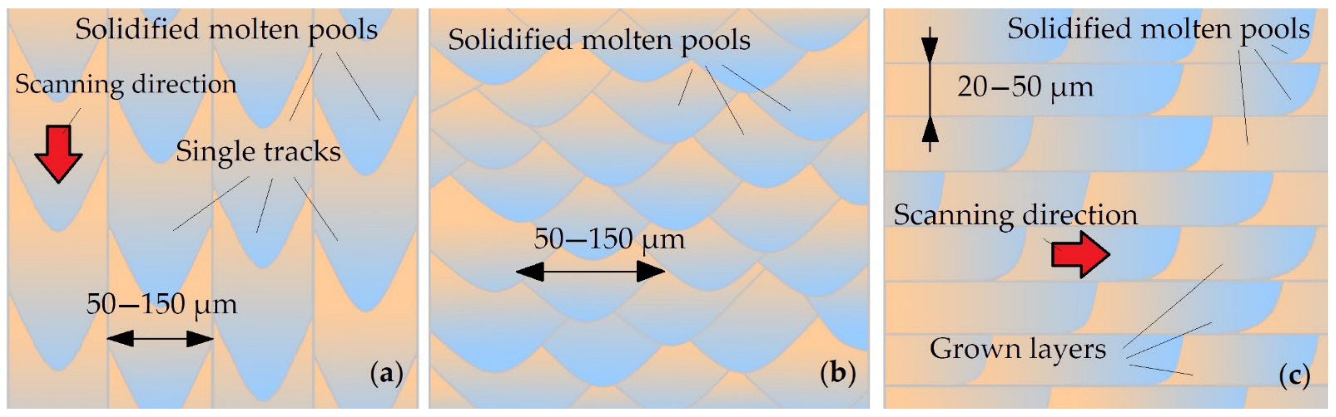
2.1. Study of the Effect of Process Parameters on Defects in LPBF
- –
- homogeneous chemical composition;
- –
- sphericity of powder particles with a shape factor from 1.0 to 2.0 (sphericity guarantees high fluidity and packing density, which leads to rapid and reproducible distribution of powder layers);
- –
- a narrow and uniform range of particle size distribution with an average value of 40 to 75 µm (the content of particles whose size is larger than the allowable or irregularly shaped particles can cause defects in the finished part).
- –
- Low coefficient of friction between particles;
- –
- Satisfactory fluidity;
- –
- Increased bulk density;
- –
- Satisfactory density after shaking.
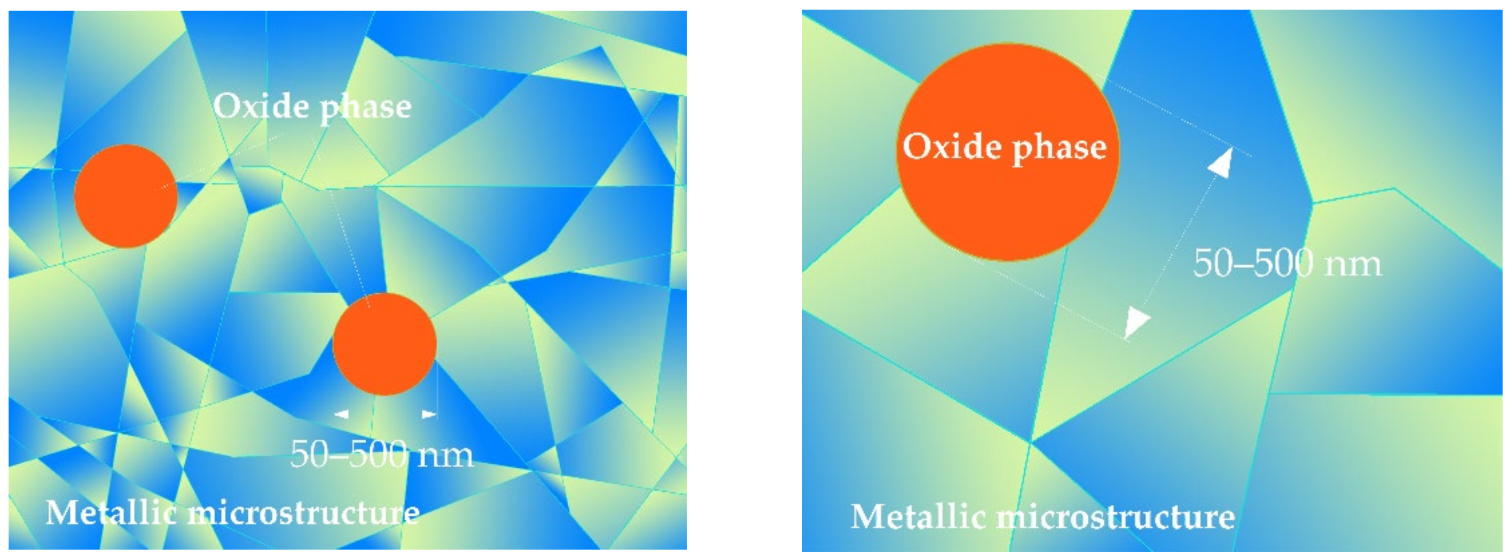
2.2. Study of the Mechanism of Formation of Structural and Surface Defects
3. Analysis of Methods for Removing Oxide Phase by Atmospheric Plasma Sources after Laser Treatment
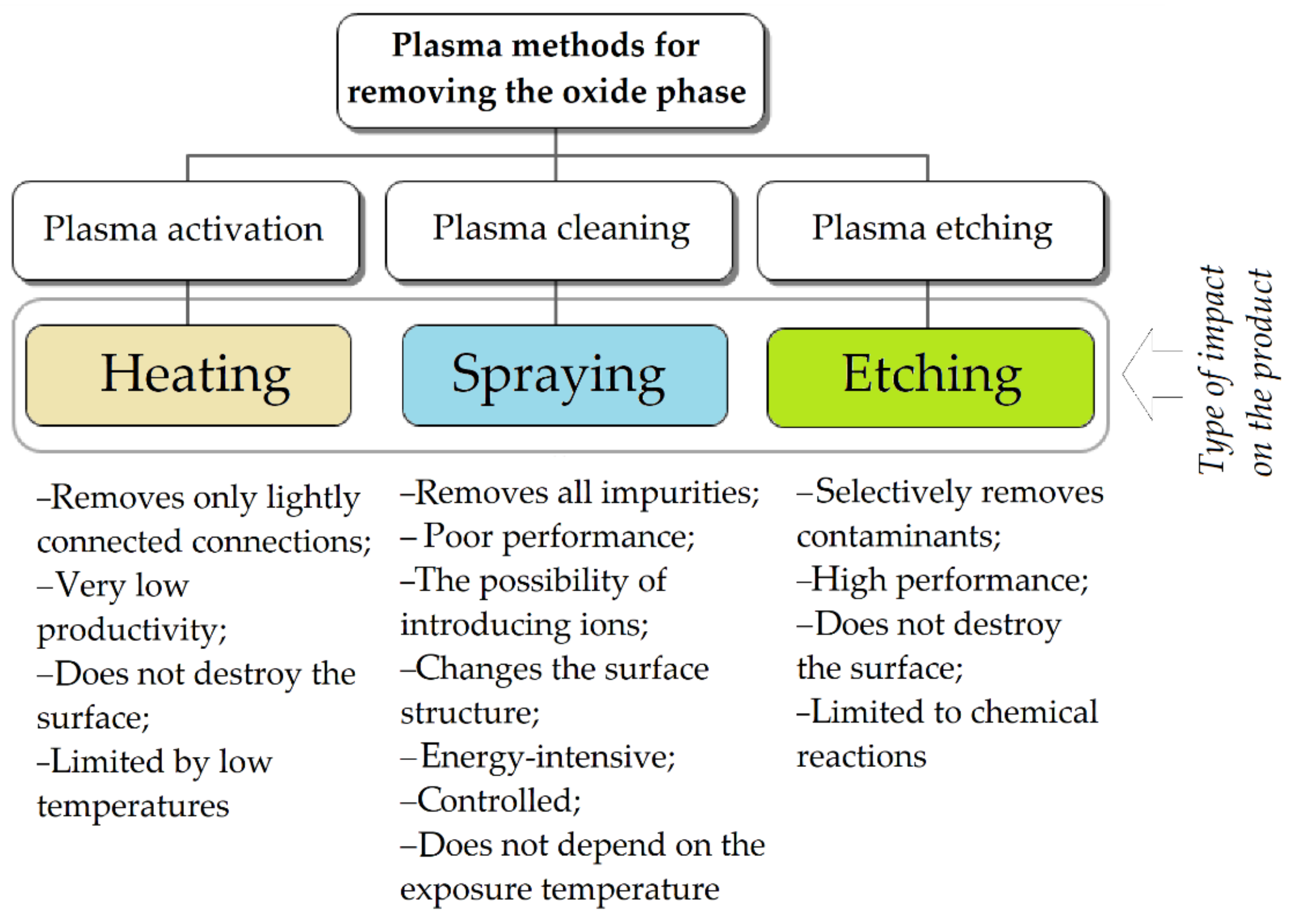
3.1. Investigation of Methods for Removing Oxide Phase
3.2. Analysis of Methods for Removinge Oxide Phase by Sources of Atmospheric Plasma
- –
- Low duration of the process;
- –
- High degree of cleanliness of the treated surface;
- –
- Homogeneity of the cleaned surface;
- –
- No changes in the structure of the substrate material;
- –
- Environmental safety;
- –
- The possibility of quick disposal of cleaning products.
4. Research of Atmospheric Plasma Sources Based on a Dielectric Barrier and Other Discharges as a Part of a Production Setup
4.1. Characteristics of Atmospheric Plasma Sources
- –
- Sources of dielectric barrier discharge (DBD);
- –
- Sources realizing pulsed direct current discharges (corona discharge);
- –
- HF and SHF frequency sources.
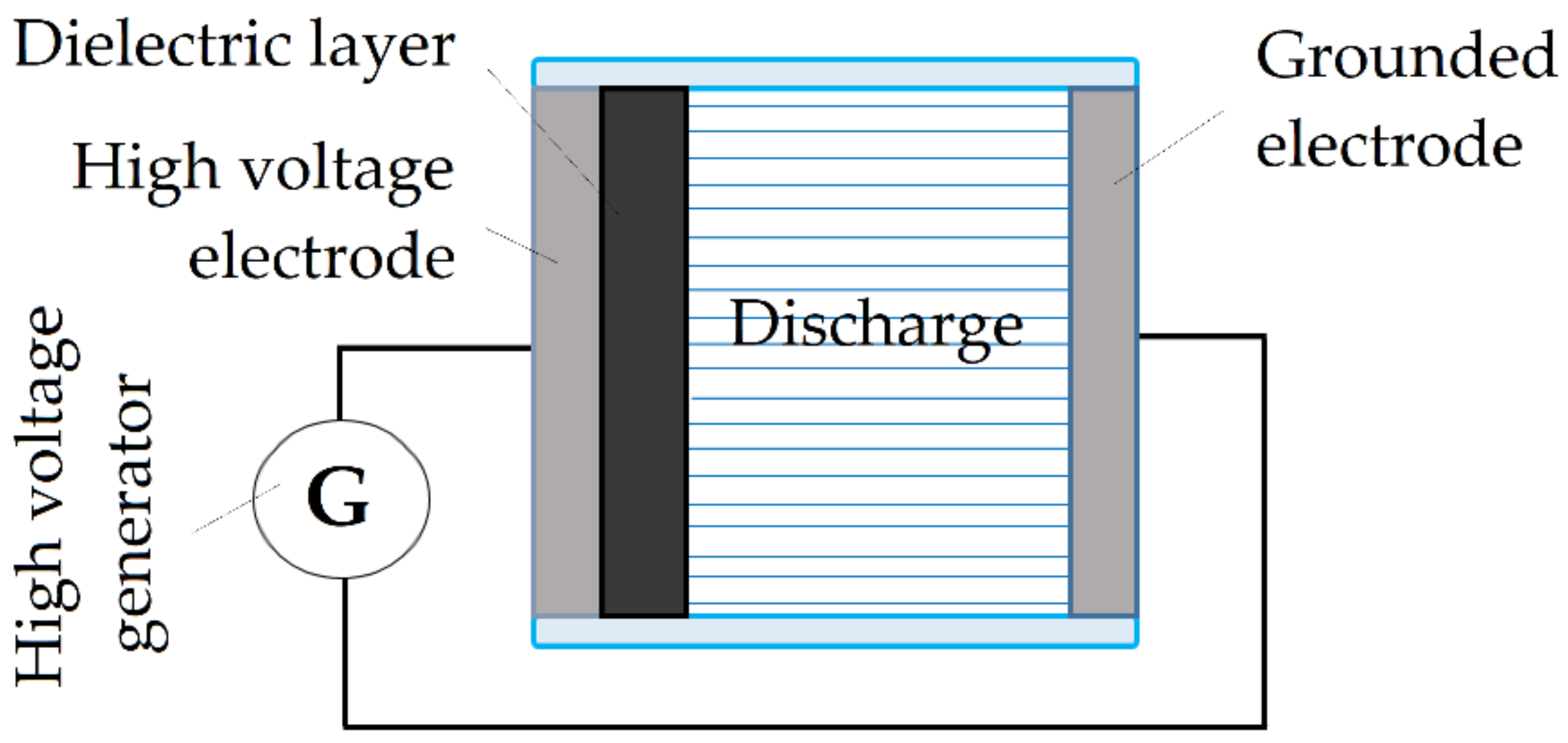
4.2. Sources of Dielectric Barrier Discharge
4.3. Sources of Corona Discharge
4.4. High Frequency and Super High Frequency Discharges
5. Conclusions
6. Patents
Author Contributions
Funding
Institutional Review Board Statement
Informed Consent Statement
Data Availability Statement
Acknowledgments
Conflicts of Interest
References
- Aversa, A.; Marchese, G.; Saboori, A.; Bassini, E.; Manfredi, D.; Biamino, S.; Ugues, D.; Fino, P.; Lombardi, M. New Aluminum Alloys Specifically Designed for Laser Powder Bed Fusion: A Review. Materials 2019, 12, 1007. [Google Scholar] [CrossRef] [PubMed] [Green Version]
- Denti, L. Additive Manufactured A357.0 Samples Using the Laser Powder Bed Fusion Technique: Shear and Tensile Performance. Metals 2018, 8, 670. [Google Scholar] [CrossRef] [Green Version]
- Sova, A.; Grigoriev, S.; Okunkova, A.; Smurov, I. Potential of cold gas dynamic spray as additive manufacturing technology. Int. J. Adv. Manuf. Technol. 2013, 69, 2269–2278. [Google Scholar] [CrossRef]
- Sova, A.; Grigoriev, S.; Okunkova, A.; Bertrand, P.; Smurov, I. Cold spraying: From process fundamentals towards advanced applications. Surf. Coat. Technol. 2015, 268, 77–84. [Google Scholar]
- Notenboom, G.; Maerten, O. Additive mass manufacturing of composite ceramic, metal and glass microparts and multilayers from nanosized particles, using inkjet and laser technology (Acerlink). In 5th European Conference on Advanced Materials and Processes and Applications (EUROMAT 97), Proceedings of the 5th European Conference on Advanced Materials and Processes and Applications: Materials, Functionality & Design, Maastricht, The Netherlands, 21–23 April 1997; Sarton, L.A.J., Zeedijk, H.B., Eds.; Netherlands Soc Materials Science: Zwijndrecht, The Netherlands, 1997; Volume 3, p. 55. [Google Scholar]
- Kumar, M.S. Rapid Prototyping-An overview of the present state-of-the-art. In Proceedings of the 13th National Convention of Mechanical Engineers, Modern Trends in Manufacturing Technology, Maastricht, The Netherlands, 6–8 November 1997; Chaturvedi, P., Tewari, N.K., Yadav, G.S., Rao, P.V., Eds.; Concept Publ Co.: New Delhi, India, 1998; pp. 123–130. [Google Scholar]
- Aleshin, N.P.; Grigor’ev, M.V.; Shchipakov, N.A.; Prilutskii, M.A.; Murashov, V.V. Applying nondestructive testing to quality control of additive manufactured parts. Russ. J. Nondestruct. Test. 2016, 52, 600–609. [Google Scholar] [CrossRef]
- Metel, A.S.; Grigoriev, S.N.; Tarasova, T.V.; Melnik, Y.A.; Volosova, M.A.; Okunkova, A.A.; Podrabinnik, P.A.; Mustafaev, E.S. Surface Quality of Metal Parts Produced by Laser Powder Bed Fusion: Ion Polishing in Gas-Discharge Plasma Proposal. Technologies 2021, 9, 27. [Google Scholar] [CrossRef]
- Liu, D.; Lee, B.; Babkin, A.; Chang, Y. Research Progress of Arc Additive Manufacture Technology. Materials 2021, 14, 1415. [Google Scholar] [CrossRef]
- Grigor’yants, A.G.; Shiganov, I.N. Development of Domestic Equipment for Laser Additive Technologies by Melting Metallic Powders. Russ. Metall. 2020, 6, 649–653. [Google Scholar] [CrossRef]
- Ivanov, A.D.; Minaev, V.L.; Vishnyakov, G.N. A Shearograph for Nondestructive Testing of Products Obtained by Additive Technologies. Instrum. Exp. Tech. 2019, 62, 871–875. [Google Scholar] [CrossRef]
- Kurbatov, A.S.; Orekhov, A.A.; Rabinskiy, L.N.; Tushavina, O.V.; Kuznetsova, E.L. Research of The Problem of Loss of Stability of Cylindrical Thin-Walled Structures Under Intense Local Temperature Exposure. Period. Tche Quim. 2020, 17, 884–891. [Google Scholar]
- Khmyrov, R.S.; Grigoriev, S.N.; Okunkova, A.A.; Gusarov, A.V. On the possibility of selective laser melting of quartz glass. Phys. Procedia 2014, 56, 345–356. [Google Scholar] [CrossRef] [Green Version]
- Khmyrov, R.S.; Protasov, C.E.; Grigoriev, S.N.; Gusarov, A.V. Crack-free selective laser melting of silica glass: Single beads and monolayers on the substrate of the same material. Int. J. Adv. Manuf. Technol. 2016, 85, 1461–1469. [Google Scholar] [CrossRef]
- Grigoriev, S.; Peretyagin, P.; Smirnov, A.; Solis, W.; Diaz, L.A.; Fernandez, A.; Torrecillas, R. Effect of graphene addition on the mechanical and electrical properties of Al2O3 -SiCw ceramics. J. Eur. Ceram. Soc. 2017, 37, 2473–2479. [Google Scholar] [CrossRef]
- Sova, A.; Grigoriev, S.; Okunkova, A.; Smurov, I. Cold spray deposition of 316L stainless steel coatings on aluminium surface with following laser post-treatment. Surf. Coat. Technol. 2013, 235, 283–289. [Google Scholar] [CrossRef]
- Klingaa, C.G.; Mohanty, S.; Hjermitslev, A.B.; Haahr-Lillevang, L.; Hattel, J.H. Towards a digital twin of laser powder bed fusion with a focus on gas flow variables. J. Manuf. Process. 2021, 65, 312–327. [Google Scholar] [CrossRef]
- Kozior, T.; Bochnia, J. The Influence of Printing Orientation on Surface Texture Parameters in Powder Bed Fusion Technology with 316L Steel. Micromachines 2020, 11, 639. [Google Scholar] [CrossRef]
- Asnafi, N. Application of Laser-Based Powder Bed Fusion for Direct Metal Tooling. Metals 2021, 11, 458. [Google Scholar] [CrossRef]
- Grigor’ev, S.N.; Kozochkin, M.P.; Fedorov, S.V.; Porvatov, A.N.; Okun’kova, A.A. Study of Electroerosion Processing by Vibroacoustic Diagnostic Methods. Meas. Tech. 2015, 58, 878–884. [Google Scholar] [CrossRef]
- Vila, C.; Siller, H.R.; Rodriguez, C.A.; Bruscas, G.M.; Serrano, J. Economical and technological study of surface grinding versus face milling in hardened AISI D3 steel machining operations. Int. J. Prod. Econ. 2012, 138, 273–283. [Google Scholar] [CrossRef] [Green Version]
- Bekem, A.; Ozbay, B.; Bulduk, M.E. Effect of dendritic copper powder addition to polyamide 12 in selective laser sintering. J. Fac. Eng. Archit. Gazi Univ. 2021, 36, 421–431. [Google Scholar]
- Qin, Y.L.; Sun, B.H.; Zhang, H.; Ni, D.R.; Xiao, B.L.; Ma, Z.Y. Development of Selective Laser Melted Aluminum Alloys and Aluminum Matrix Composites in Aerospace Field. Chin. J. Lasers-Zhongguo Jiguang 2021, 48, 1402002. [Google Scholar]
- Wang, H.; Chen, J.Q.; Luo, H.L.; Wang, D.; Song, C.H.; Yao, X.Y.; Chen, P.; Yan, M. Bimetal printing of high entropy alloy/metallic glass by laser powder bed fusion additive manufacturing. Intermetallics 2022, 141, 107430. [Google Scholar] [CrossRef]
- Sova, A.; Okunkova, A.; Grigoriev, S.; Smurov, I. Velocity of the Particles Accelerated by a Cold Spray Micronozzle: Experimental Measurements and Numerical Simulation. J. Therm. Spray Technol. 2012, 22, 75–80. [Google Scholar] [CrossRef]
- Santecchia, E.; Spigarelli, S.; Cabibbo, M. Material Reuse in Laser Powder Bed Fusion: Side Effects of the Laser—Metal Powder Interaction. Metals 2020, 10, 341. [Google Scholar] [CrossRef] [Green Version]
- Grigoriev, S.N.; Kozochkin, M.P.; Porvatov, A.N.; Volosova, M.A.; Okunkova, A.A. Electrical discharge machining of ceramic nanocomposites: Sublimation phenomena and adaptive control. Heliyon 2019, 5, e02629. [Google Scholar] [CrossRef] [PubMed] [Green Version]
- Khorasani, M.; Ghasemi, A.; Rolfe, B.; Gibson, I. Additive manufacturing a powerful tool for the aerospace industry. Rapid Prototyp. J. 2022, 28, 87–100. [Google Scholar] [CrossRef]
- Mindt, H.W.; Desmaison, O.; Megahed, M.; Peralta, A.; Neumann, J. Modeling of Powder Bed Manufacturing Defects. J. Mater. Eng. Perform. 2018, 27, 32–43. [Google Scholar] [CrossRef]
- Metel, A.S.; Grigoriev, S.N.; Tarasova, T.V.; Filatova, A.A.; Sundukov, S.K.; Volosova, M.A.; Okunkova, A.A.; Melnik, Y.A.; Podrabinnik, P.A. Influence of Postprocessing on Wear Resistance of Aerospace Steel Parts Produced by Laser Powder Bed Fusion. Technologies 2020, 8, 73. [Google Scholar] [CrossRef]
- Mahmood, M.A.; Ur Rehman, A.; Pitir, F.; Salamci, M.U.; Mihailescu, I.N. Laser Melting Deposition Additive Manufacturing of Ti6Al4V Biomedical Alloy: Mesoscopic In-Situ Flow Field Mapping via Computational Fluid Dynamics and Analytical Modelling with Empirical Testing. Materials 2021, 14, 7749. [Google Scholar] [CrossRef]
- Dostovalov, A.V.; Korolkov, V.P.; Babin, S.A. Formation of thermochemical laser-induced periodic surface structures on Ti films by a femtosecond IR Gaussian beam: Regimes, limiting factors, and optical properties. Appl. Phys. B-Lasers Opt. 2017, 123, 30. [Google Scholar] [CrossRef]
- Gusarov, A.V.; Grigoriev, S.N.; Volosova, M.A.; Melnik, Y.A.; Laskin, A.; Kotoban, D.V.; Okunkova, A.A. On productivity of laser additive manufacturing. J. Mater. Process. Technol. 2018, 261, 213–232. [Google Scholar] [CrossRef]
- Yadroitsev, I.; Bertrand, P.H.; Antonenkova, G.; Grigoriev, S.; Smurov, I. Use of track/layer morphology to develop functional parts by selectivelaser melting. J. Laser Appl. 2013, 25, 052003. [Google Scholar] [CrossRef]
- Kotoban, D.; Grigoriev, S.; Okunkova, A.; Sova, A. Influence of a shape of single track on deposition efficiency of 316L stainless steel powder in cold spray. Surf. Coat. Technol. 2017, 309, 951–958. [Google Scholar] [CrossRef]
- Doubenskaia, M.; Pavlov, M.; Grigoriev, S.; Tikhonova, E.; Smurov, I. Comprehensive Optical Monitoring of Selective Laser Melting. J. Laser Micro Nanoeng. 2012, 7, 236–243. [Google Scholar] [CrossRef]
- Glaziev, S.Y. The discovery of regularities of change of technological orders in the central economics and mathematics institute of the soviet academy of sciences. Econ. Math. Methods 2018, 54, 17–30. [Google Scholar] [CrossRef]
- Korotayev, A.V.; Tsirel, S.V. A spectral analysis of world GDP dynamics: Kondratiev waves, Kuznets swings, Juglar and Kitchin cycles in global economic development, and the 2008–2009 economic crisis. Struct. Dyn. 2010, 4, 3–57. [Google Scholar] [CrossRef]
- Perez, C. Technological revolutions and techno-economic paradigms. Camb. J. Econ. 2010, 34, 185–202. [Google Scholar] [CrossRef] [Green Version]
- Wonglimpiyarat, J. Towards the sixth Kondratieff cycle of nano revolution. Int. J. Nanotechnol. Mol. Comput. 2011, 3, 87–100. [Google Scholar] [CrossRef]
- Smurov, I.; Doubenskaia, M.; Grigoriev, S.; Nazarov, A. Optical Monitoring in Laser Cladding of Ti6Al4V. J. Spray Technol. 2012, 21, 1357–1362. [Google Scholar] [CrossRef]
- Scotti, F.M.; Teixeira, F.R.; da Silva, L.J.; de Araujo, D.B.; Reis, R.P.; Scotti, A. Thermal management in WAAM through the CMT Advanced process and an active cooling technique. J. Manuf. Process. 2020, 57, 23–35. [Google Scholar] [CrossRef]
- Duman, B.; Ozsoy, K. A deep learning-based approach for defect detection in powder bed fusion additive manufacturing using transfer learning. J. Fac. Eng. Archit. Gazi Univ. 2022, 37, 361–375. [Google Scholar]
- Sing, S.L.; Yeong, W.Y.; Wiria, F.E.; Tay, B.Y.; Zhao, Z.Q.; Zhao, L.; Tian, Z.L.; Yang, S.F. Direct selective laser sintering and melting of ceramics: A review. Rapid Prototyp. J. 2017, 23, 611–623. [Google Scholar] [CrossRef]
- Deirmina, F.; Davies, P.A.; Casati, R. Effects of Powder Atomization Route and Post-Processing Thermal Treatments on the Mechanical Properties and Fatigue Resistance of Additively Manufactured 18Ni300 Maraging Steel. Adv. Eng. Mater. 2021, 24, 2101011. [Google Scholar] [CrossRef]
- Yan, J.; Zhou, Y.; Gu, R.; Zhang, X.; Quach, W.-M.; Yan, M. A Comprehensive Study of Steel Powders (316L, H13, P20 and 18Ni300) for Their Selective Laser Melting Additive Manufacturing. Metals 2019, 9, 86. [Google Scholar] [CrossRef] [Green Version]
- Metel, A.; Tarasova, T.; Gutsaliuk, E.; Khmyrov, R.; Egorov, S.; Grigoriev, S. Possibilities of Additive Technologies for the Manufacturing of Tooling from Corrosion-Resistant Steels in Order to Protect Parts Surfaces from Thermochemical Treatment. Metals 2021, 11, 1551. [Google Scholar] [CrossRef]
- Fomin, V.M.; Golyshev, A.A.; Malikov, A.G.; Orishich, A.M.; Filippov, A.A. Creation of A Functionally Gradient Material by the Selective Laser Melting Method. J. Appl. Mech. Tech. Phys. 2020, 61, 878–887. [Google Scholar] [CrossRef]
- Akopyan, T.K.; Letyagin, N.V.; Avxentieva, N.N. High-tech alloys based on Al-Ca-La(-Mn) eutectic system for casting, metal forming and selective laser melting. Non-Ferr. Met. 2020, 1, 52–59. [Google Scholar] [CrossRef]
- Mazeeva, A.K.; Staritsyn, M.V.; Bobyr, V.V.; Manninen, S.A.; Kuznetsov, P.A.; Klimov, V.N. Magnetic properties of Fe-Ni permalloy produced by selective laser melting. J. Alloy. Compd. 2020, 814, 152315. [Google Scholar] [CrossRef]
- Samodurova, M.; Logachev, I.; Shaburova, N.; Samoilova, O.; Radionova, L.; Zakirov, R.; Pashkeev, K.; Myasoedov, V.; Trofimov, E. A Study of the Structural Characteristics of Titanium Alloy Products Manufactured Using Additive Technologies by Combining the Selective Laser Melting and Direct Metal Deposition Methods. Materials 2019, 12, 3269. [Google Scholar] [CrossRef] [Green Version]
- Okunkova, A.; Peretyagin, P.; Vladimirov, Y.; Volosova, M.; Torrecillas, R.; Fedorov, S.V. Laser-beam modulation to improve efficiency of selecting laser melting for metal powders. In Proceedings of the Conference on Laser Sources and Applications II, Laser Sources and Applications II, Laser Sources and Applications II, Brussels, Belgium, 14–17 April 2014; Mackenzie, J.I., Jelinkova, H., Taira, T., Ahmed, M.A., Eds.; SPIE-Int Soc Optical Engineering: Bellingham, WA, USA, 2014; Volume 9135, p. 913524. [Google Scholar]
- Gusarov, A.V.; Okun’kova, A.A.; Peretyagin, P.Y.; Zhirnov, I.V.; Podrabinnik, P.A. Means of Optical Diagnostics of Selective Laser Melting with Non-Gaussian Beams. Meas. Tech. 2015, 58, 872–877. [Google Scholar] [CrossRef]
- Gu, R.N.; Wong, K.S.; Yan, M. Laser additive manufacturing of typical highly reflective materials-gold, silver and copper. Sci. Sin. Phys. Mech. Astron. 2020, 50, 034204. [Google Scholar]
- Klotz, U.E.; Tiberto, D.; Held, F. Optimization of 18-karat yellow gold alloys for the additive manufacturing of jewelry and watch parts. Gold Bull. 2017, 50, 111–121. [Google Scholar] [CrossRef]
- Chauveau, D. Review of NDT and process monitoring techniques usable to produce high-quality parts by welding or additive manufacturing. Weld. World 2018, 62, 1097–1118. [Google Scholar] [CrossRef]
- Shi, Y.S.; Zhang, J.L.; Wen, S.F.; Song, B.; Yan, C.Z.; Wei, Q.S.; Wu, J.M.; Yin, Y.J.; Zhou, J.X.; Chen, R.; et al. Additive manufacturing and foundry innovation. China Foundry 2021, 18, 286–295. [Google Scholar] [CrossRef]
- Yang, L.; Tang, S.Y.; Fan, Z.T.; Jiang, W.M.; Liu, X.W. Rapid casting technology based on selective laser sintering. China Foundry 2021, 18, 296–306. [Google Scholar] [CrossRef]
- Abdul Rani, A.M.; Fua-Nizan, R.; Din, M.Y. Manufacturing methods for medical artificial prostheses—A review. Malays. J. Fundam. Appl. Sci. 2017, 13, 464–469. [Google Scholar]
- Li, Y.; Li, D.C.; Lu, B.H.; Gao, D.J.; Zhou, J. Current status of additive manufacturing for tissue engineering scaffold. Rapid Prototyp. J. 2015, 21, 747–762. [Google Scholar] [CrossRef]
- Ojo, O.O.; Taban, E. Defects and post-manufacturing processes of additively manufactured steels: A Review (Part 2). Mater. Test. 2020, 62, 835–848. [Google Scholar]
- Filatova, A.; Tarasova, T.; Peretyagin, P. Developing processes for manufacturing metal aviation technology components using powder bed fusion methods. MATEC Web Conf. 2019, 298, 00116. [Google Scholar] [CrossRef]
- Cortina, M.; Arrizubieta, J.I.; Calleja, A.; Ukar, E.; Alberdi, A. Case Study to Illustrate the Potential of Conformal Cooling Channels for Hot Stamping Dies Manufactured Using Hybrid Process of Laser Metal Deposition (LMD) and Milling. Metals 2018, 8, 102. [Google Scholar] [CrossRef] [Green Version]
- Zhao, Y.; Li, F.; Chen, S.; Lu, Z.Y. Unit block-based process planning strategy of WAAM for complex shell-shaped component. Int. J. Adv. Manuf. Technol. 2019, 104, 3915–3927. [Google Scholar] [CrossRef]
- Han, P. Additive Design and Manufacturing of Jet Engine Parts. Engineering 2017, 3, 648–652. [Google Scholar] [CrossRef]
- Ghaffari, M.; Nemani, A.V.; Rafieazad, M.; Nasiri, A. Effect of Solidification Defects and HAZ Softening on the Anisotropic Mechanical Properties of a Wire Arc Additive-Manufactured Low-Carbon Low-Alloy Steel Part. JOM 2019, 71, 4215–4224. [Google Scholar] [CrossRef]
- Sun, X.F.; Song, W.; Liang, J.J.; Li, J.G.; Zhou, Y.Z. Research and Development in Materials and Processes of Superalloy Fabricated by Laser Additive Manufacturing. Acta Metall. Sin. 2021, 57, 1471–1483. [Google Scholar]
- Magerramova, L.; Isakov, V.; Shcherbinina, L.; Gukasyan, S.; Petrov, M.; Povalyukhin, D.; Volosevich, D.; Klimova-Korsmik, O. Design, Simulation and Optimization of an Additive Laser-Based Manufacturing Process for Gearbox Housing with Reduced Weight Made from AlSi10Mg Alloy. Metals 2022, 12, 67. [Google Scholar] [CrossRef]
- Brailovski, V.; Kalinicheva, V.; Letenneur, M.; Lukashevich, K.; Sheremetyev, V.; Prokoshkin, S. Control of Density and Grain Structure of a Laser Powder Bed-Fused Superelastic Ti-18Zr-14Nb Alloy: Simulation-Driven Process Mapping. Metals 2020, 10, 1697. [Google Scholar] [CrossRef]
- Ahsan, F.; Razmi, J.; Ladani, L. Process Parameter Optimization in Metal Laser-Based Powder Bed Fusion Using Image Processing and Statistical Analyses. Metals 2022, 12, 87. [Google Scholar] [CrossRef]
- Gurin, V.D.; Kotoban, D.V.; Podrabinnik, P.A.; Zhirnov, I.V.; Peretyagin, P.Y.; Okunkova, A.A. Modeling of 3D technological fields and research of principal perspectives and limits in productivity improvement of selective laser melting. Mech. Ind. 2016, 17, 714. [Google Scholar] [CrossRef] [Green Version]
- Zhirnov, I.V.; Podrabinnik, P.A.; Okunkova, A.A.; Gusarov, A.V. Laser beam profiling: Experimental study of its influence on single-track formation by selective laser melting. Mech. Ind. 2015, 16, 709. [Google Scholar] [CrossRef] [Green Version]
- Yan, Q.; Song, B.; Shi, Y.S. Comparative study of performance comparison of AlSi10Mg alloy prepared by selective laser melting and casting. J. Mater. Sci. Technol. 2020, 41, 199–208. [Google Scholar] [CrossRef]
- Albu, M.; Panzirsch, B.; Schröttner, H.; Mitsche, S.; Reichmann, K.; Poletti, M.C.; Kothleitner, G. High-Resolution Microstructure Characterization of Additively Manufactured X5CrNiCuNb17-4 Maraging Steel during Ex and In Situ Thermal Treatment. Materials 2021, 14, 7784. [Google Scholar] [CrossRef] [PubMed]
- Tian, Z.; Zhang, C.; Wang, D.; Liu, W.; Fang, X.; Wellmann, D.; Zhao, Y.; Tian, Y. A Review on Laser Powder Bed Fusion of Inconel 625 Nickel-Based Alloy. Appl. Sci. 2020, 10, 81. [Google Scholar] [CrossRef] [Green Version]
- Sotov, A.V.; Agapovichev, A.V.; Smelov, V.G.; Kokareva, V.V.; Zenina, M.V. Investigation of the Ni-Co-Cr alloy microstructure for the manufacturing of combustion chamber GTE by selective laser melting. Int. J. Adv. Manuf. Technol. 2019, 101, 3047–3053. [Google Scholar] [CrossRef]
- Zegzulka, J.; Gelnar, D.; Jezerska, L. Characterization and fowability methods for metal powders. Sci. Rep. 2020, 10, 21004. [Google Scholar] [CrossRef]
- Wang, L.; Li, E.L.; Shen, H.; Zou, R.P.; Yu, A.B.; Zhou, Z.Y. Adhesion effects on spreading of metal powders in selective laser melting. Powder Technol. 2020, 363, 602–610. [Google Scholar] [CrossRef]
- Zakharov, O.V.; Brzhozovskii, B.M. Accuracy of centering during measurement by roundness gauges. Meas. Tech. 2006, 49, 1094–1097. [Google Scholar] [CrossRef]
- Rezchikov, A.F.; Kochetkov, A.V.; Zakharov, O.V. Mathematical models for estimating the degree of influence of major factors on performance and accuracy of coordinate measuring machines. MATEC Web Conf. 2017, 129, 01054. [Google Scholar] [CrossRef] [Green Version]
- Zakharov, O.V.; Balaev, A.F.; Kochetkov, A.V. Modeling Optimal Path of Touch Sensor of Coordinate Measuring Machine Based on Traveling Salesman Problem Solution. Procedia Eng. 2017, 206, 1458–1463. [Google Scholar] [CrossRef]
- Grigoriev, S.N.; Metel, A.S.; Tarasova, T.V.; Filatova, A.A.; Sundukov, S.K.; Volosova, M.A.; Okunkova, A.A.; Melnik, Y.A.; Podrabinnik, P.A. Effect of Cavitation Erosion Wear, Vibration Tumbling, and Heat Treatment on Additively Manufactured Surface Quality and Properties. Metals 2020, 10, 1540. [Google Scholar] [CrossRef]
- Lou, X.Y.; Andresen, P.L.; Rebak, R.B. Oxide inclusions in laser additive manufactured stainless steel and their effects on impact toughness and stress corrosion cracking behavior. J. Nucl. Mater. 2018, 499, 182–190. [Google Scholar] [CrossRef]
- Zai, L.; Zhang, C.; Wang, Y.; Guo, W.; Wellmann, D.; Tong, X.; Tian, Y. Laser Powder Bed Fusion of Precipitation-Hardened Martensitic Stainless Steels: A Review. Metals 2020, 10, 255. [Google Scholar] [CrossRef] [Green Version]
- Metel, A.S.; Stebulyanin, M.M.; Fedorov, S.V.; Okunkova, A.A. Power Density Distribution for Laser Additive Manufacturing (SLM): Potential, Fundamentals and Advanced Applications. Technologies 2019, 7, 5. [Google Scholar] [CrossRef] [Green Version]
- Cheng, B.; Shrestha, S.; Chou, K. Stress and deformation evaluations of scanning strategy effect in selective laser melting. Addit. Manuf. 2016, 12B, 240–251. [Google Scholar]
- Aota, L.S.; Bajaj, P.; Zilnyk, K.D.; Ponge, D.; Sandim, H.R.Z. The origin of abnormal grain growth upon thermomechanical processing of laser powder-bed fusion alloys. Materialia 2021, 20, 101243. [Google Scholar] [CrossRef]
- Gong, H.; Nadimpalli, V.K.; Rafi, K.; Starr, T.; Stucker, B. Micro-CT Evaluation of Defects in Ti-6Al-4V Parts Fabricated by Metal Additive Manufacturing. Technologies 2019, 7, 44. [Google Scholar] [CrossRef] [Green Version]
- Zhang, P.; He, A.N.; Liu, F.; Zhang, K.; Jiang, J.; Zhang, D.Z. Evaluation of Low Cycle Fatigue Performance of Selective Laser Melted Titanium Alloy Ti–6Al–4V. Metals 2019, 9, 1041. [Google Scholar] [CrossRef] [Green Version]
- Loginova, I.S.; Bykovskiy, D.P.; Solonin, A.N.; Prosviryakov, A.S.; Cheverikin, V.V.; Pozdniakov, A.V.; Petrovskiy, V.N. Peculiarities of the Microstructure and Properties of Parts Produced by the Direct Laser Deposition of 316L Steel Powder. Russ. J. Non-Ferr. Met. 2019, 60, 87–94. [Google Scholar] [CrossRef]
- Pelevin, I.A.; Ozherelkov, D.Y.; Chernyshikhin, S.V.; Nalivaiko, A.Y.; Gromov, A.A.; Chzhan, V.B.; Terekhin, E.A.; Tereshina, I.S. Selective laser melting of Nd-Fe-B: Single track study. Mater. Lett. 2022, 315, 131947. [Google Scholar] [CrossRef]
- Tan, J.H.; Wong, W.L.E.; Dalgarno, K.W. An overview of powder granulometry on feedstock and part performance in the selective laser melting process. Addit. Manuf. 2017, 18, 228–255. [Google Scholar] [CrossRef] [Green Version]
- Zhang, X.B.; Cheng, B.; Tuffile, C. Simulation study of the spatter removal process and optimization design of gas flow system in laser powder bed fusion. Addit. Manuf. 2020, 32, 101049. [Google Scholar] [CrossRef]
- Vilanova, M.; Escribano-García, R.; Guraya, T.; San Sebastian, M. Optimizing Laser Powder Bed Fusion Parameters for IN-738LC by Response Surface Method. Materials 2020, 13, 4879. [Google Scholar] [CrossRef] [PubMed]
- Ogawahara, M.; Sasaki, S. Effects of Defects and Inclusions on the Fatigue Properties of Inconel 718 Fabricated by Laser Powder Bed Fusion Followed by HIP. Mater. Trans. 2021, 62, 631–635. [Google Scholar] [CrossRef]
- Aliprandi, P.; Giudice, F.; Guglielmino, E.; Sili, A. Tensile and Creep Properties Improvement of Ti-6Al-4V Alloy Specimens Produced by Electron Beam Powder Bed Fusion Additive Manufacturing. Metals 2019, 9, 1207. [Google Scholar] [CrossRef] [Green Version]
- Fang, M.H.; Hu, F.G.; Han, Y.F.; Le, J.W.; Xi, J.J.; Song, J.W.; Ke, L.D.; Xiao, M.L.; Lu, W.J. Controllable mechanical anisotropy of selective laser melted Ti6Al4V: A new perspective into the effect of grain orientations and primary grain structure. Mater. Sci. Eng. A-Struct. Mater. Prop. Microstruct. Process. 2021, 827, 142031. [Google Scholar] [CrossRef]
- Liu, J.; Liu, J.; Li, Y.; Zhang, R.; Zeng, Z.; Zhu, Y.; Zhang, K.; Huang, A. Effects of Post Heat Treatments on Microstructures and Mechanical Properties of Selective Laser Melted Ti6Al4V Alloy. Metals 2021, 11, 1593. [Google Scholar] [CrossRef]
- Wang, C.; Yi, J.Z.; Qin, L.Y.; Wang, W.D.; Wang, X.M.; Yang, G. Effects of double annealing on microstructure and mechanical properties of laser melting deposition TA15 titanium alloy. Mater. Res. Express 2019, 6, 116526. [Google Scholar] [CrossRef]
- Lin, D.Y.; Xu, L.Y.; Li, X.J.; Jing, H.Y.; Qin, G.; Pang, H.N.; Minami, F. A Si-containing FeCoCrNi high-entropy alloy with high strength and ductility synthesized in situ via selective laser melting. Addit. Manuf. 2020, 35, 101340. [Google Scholar] [CrossRef]
- Miao, X.; Liu, X.; Lu, P.; Han, J.; Duan, W.; Wu, M. Influence of Scanning Strategy on the Performances of GO-Reinforced Ti6Al4V Nanocomposites Manufactured by SLM. Metals 2020, 10, 1379. [Google Scholar] [CrossRef]
- Vrancken, B.; Ganeriwala, R.K.; Matthews, M.J. Analysis of laser-induced microcracking in tungsten under additive manufacturing conditions: Experiment and simulation. Acta Mater. 2020, 194, 464–472. [Google Scholar] [CrossRef]
- Tian, Y.; Tomus, D.; Rometsch, P.; Wu, X. Influences of processing parameters on surface roughness of Hastelloy X produced by selective laser melting. Addit. Manuf. 2017, 13, 103–112. [Google Scholar] [CrossRef]
- Tangsopha, W.; Thongsri, J.; Busayaporn, W. Simulation of ultrasonic cleaning and ways to improve the efficiency. In Proceedings of the 5th International Electrical Engineering Congress, Pattaya, Thailand, 8–10 March 2017; IEEE345: New York, NY, USA, 2017. [Google Scholar]
- Fatyukhin, D.S.; Nigmetzyanov, R.I.; Prikhodko, V.M.; Sukhov, A.V.; Sundukov, S.K. A Comparison of the Effects of Ultrasonic Cavitation on the Surfaces of 45 and 40Kh Steels. Metals 2022, 12, 138. [Google Scholar] [CrossRef]
- Gavrilov, N.V.; Mesyats, G.A.; Nikulin, S.P.; Radkovskii, G.V.; Elkind, A.; Perry, A.J.; Treglio, J.R. New broad beam gas ion source for industrial application. J. Vac. Sci. Technol. A 1996, 14, 1050–1055. [Google Scholar] [CrossRef]
- Kolikov, V.; Bogomaz, A.; Budin, A. Powerful Pulsed Plasma Generators: Research and Application; Springer: Cham, Switzerland, 2018; Introduction Chapter; pp. 1–12. [Google Scholar]
- Walton, S.G.; Cothran, C.D.; Amatucci, W.E. Electron Beam Propagation in Magnetic Fields. IEEE Trans. Plasma Sci. 2011, 39, 2574–2575. [Google Scholar] [CrossRef]
- Yu, Y.C.; Bai, S.; Wang, S.T.; Hu, A.M. Ultra-Short Pulsed Laser Manufacturing and Surface Processing of Microdevices. Engineering 2018, 4, 779–786. [Google Scholar] [CrossRef]
- Korkmaz, K.; Ribalko, A.V. Effect of pulse shape and energy on the surface roughness and mass transfer in the electrospark coating process. Kov. Mater. Met. Mater. 2011, 49, 265–270. [Google Scholar] [CrossRef]
- Feng, S.; Xia, M.; Ge, C.C. Consecutive induction melting of nickel-based superalloy in electrode induction gas atomization. Chin. Phys. Soc. 2017, 26, 6. [Google Scholar] [CrossRef]
- Antonov, D.; Strizhak, P. Explosive Disintegration of Two-Component Droplets in a Gas-Flow at Its Turbulization. Therm. Sci. 2019, 23, 2983–2993. [Google Scholar] [CrossRef] [Green Version]
- Ivanov, Y.F.; Lopatin, I.V.; Petrikova, E.A.; Rygina, M.E.; Tolkachev, O.S.; Shimanskii, V.I. Structure and Properties of Silumin Surface after Vacuum Arc Plasma-Assisted Deposition of Coatings Irradiated by Low Energy High Current Pulsed Electron Beam. Russ. Phys. J. 2020, 62, 2106–2111. [Google Scholar] [CrossRef]
- Bardos, L.; Barankova, H. Cold atmospheric plasma: Sources, processes, and applications. Thin Solid Film. 2010, 518, 6705–6713. [Google Scholar] [CrossRef]
- Jiang, S.; Qiu, L.W.; Li, Z.; Zhang, L.; Rao, J.F. A New All-Solid-State Bipolar High-Voltage Multilevel Generator for Dielectric Barrier Discharge. IEEE Trans. Plasma Sci. 2020, 48, 1076–1081. [Google Scholar] [CrossRef]
- Tatar, N.; Tuzlah, M.; Bahce, E. Investigation of the Lattice Production of Removable Dental Prostheses with CoCr Alloy Using Additive Manufacturing. J. Mater. Eng. Perform. 2021, 30, 6722–6731. [Google Scholar] [CrossRef]
- Navinsek, B.; Panjan, P.; Milosev, I. PVD coatings as an environmentally clean alternative to electroplating and electroless processes. Surf. Coat. Technol. 1999, 116, 476–487. [Google Scholar] [CrossRef]
- Kovalenko, V.A. Use of the vacuum arc discharge for the surface modification. Fundam. Mech. Low-Energy-Beam-Modif. Surf. Growth Process. 2000, 585, 129–134. [Google Scholar] [CrossRef]
- Kikuchi, E.; Kikuchi, Y.; Hirao, M. Monitoring and Analysis of Solvent Emissions from Metal Cleaning Processes for Practical Process Improvement. Ann. Occup. Hyg. 2012, 56, 829–842. [Google Scholar] [PubMed]
- Yoon, S.S.; Khang, D.Y. Facile and Clean Release of Vertical Si Nanowires by Wet Chemical Etching Based on Alkali Hydroxides. Small 2013, 9, 905–912. [Google Scholar] [CrossRef]
- Razab, M.K.A.A.; Noor, A.M.; Jaafar, M.S.; Abdullah, N.H.; Suhaimi, F.M.; Mohamed, M.; Adam, N.; Yusuf, N.A.A.N. A review of incorporating Nd:YAG laser cleaning principal in automotive industry. J. Radiat. Res. Appl. Sci. 2018, 11, 393–402. [Google Scholar] [CrossRef] [Green Version]
- Kuznetsov, A.P.; Buzinskij, O.I.; Gubsky, K.L.; Nikitina, E.A.; Savchenkov, A.V.; Tarasov, B.A.; Tugarinov, S.N. Development of a laser cleaning method for the first mirror surface of the charge exchange recombination spectroscopy diagnostics on ITER. Phys. At. Nucl. 2015, 78, 1677–1685. [Google Scholar] [CrossRef]
- Metel, A.; Grigoriev, S.; Volosova, M.; Melnik, Y.; Mustafaev, E. Synthesis of aluminum nitride coatings assisted by fast argon atoms in a magnetron sputtering system with a separate input of argon and nitrogen. Surf. Coat. Technol. 2020, 398, 126078. [Google Scholar] [CrossRef]
- Mizerov, A.M.; Timoshnev, S.N.; Nikitina, E.V.; Sobolev, M.S.; Shubin, K.Y.; Berezovskaia, T.N.; Mokhov, D.V.; Lundin, W.V.; Nikolaev, A.E.; Bouravleuv, A.D. On the Specific Features of the Plasma-Assisted MBE Synthesis of n+-GaN Layers on GaN/c-Al2O3 Templates. Semiconductors 2019, 53, 1187–1191. [Google Scholar] [CrossRef]
- Kamensky, E. Digital technologies in the Russians’ everyday life: Analysis based on the opinion surveys. Ann. XXI 2020, 186, 134–142. [Google Scholar] [CrossRef]
- Dai, Y.; Zhang, M.; Li, Q.; Wen, L.; Wang, H.; Chu, J. Separated Type Atmospheric Pressure Plasma Microjets Array for Maskless Microscale Etching. Micromachines 2017, 8, 173. [Google Scholar] [CrossRef] [Green Version]
- Su, X.; Ji, C.; Xu, Y.; Li, D.; Walker, D.; Yu, G.; Li, H.; Wang, B. Surface Texture Evolution of Fused Silica in a Combined Process of Atmospheric Pressure Plasma Processing and Bonnet Polishing. Coatings 2019, 9, 676. [Google Scholar] [CrossRef] [Green Version]
- Yen, T.; Chin, A.; Gritsenko, V. High Performance All Nonmetal SiNx Resistive Random Access Memory with Strong Process Dependence. Sci. Rep. 2020, 10, 2807. [Google Scholar] [CrossRef] [PubMed] [Green Version]
- Solovyev, A.A.; Lebedynskiy, A.M.; Shipilova, A.V.; Ionov, I.V.; Smolyanskiy, E.A.; Lauk, A.L.; Remnev, G.E.; Maslov, A.S. Scale-up of Solid Oxide Fuel Cells with Magnetron Sputtered Electrolyte. Fuel Cells 2017, 17, 378–382. [Google Scholar] [CrossRef]
- Zolotukhin, D.B.; Oks, E.M.; Tyunkov, A.V.; Yakovlev, E.V.; Yushkov, Y.G. Effect of a dielectric cavity on the ion etching of dielectrics by electron beam-produced plasma generated by a forevacuum plasma electron source. Vacuum 2021, 192, 110483. [Google Scholar] [CrossRef]
- Marinov, D.; de Marneffe, J.F.; Smets, Q.; Arutchelvan, G.; Bal, K.M.; Voronina, E.; Rakhimova, T.; Mankelevich, Y.; El Kazzi, S.; Mehta, A.N.; et al. Reactive plasma cleaning and restoration of transition metal dichalcogenide monolayers. NPJ 2D Mater. Appl. 2021, 5, 17. [Google Scholar] [CrossRef]
- Rakhimberlinova, Z.B.; Takibayeva, A.T.; Nazarova, O.G.; Iskakov, A.R.; Musina, G.N.; Kulakov, I.V. Activation Method of Cleaning Process Gas. News Natl. Acad. Sci. Repub. Kazakhstan Ser. Chem. Technol. 2020, 3, 73–79. [Google Scholar] [CrossRef]
- Vizir, A.V.; Oks, E.M.; Yushkov, G.Y. Broad-beam high-current DC ion source based on a two-stage glow discharge plasma. Rev. Sci. Instrum. 2010, 81, 02B304. [Google Scholar] [CrossRef]
- Gusev, V.V.; Dolgopolov, V.M.; Slovetskii, D.I.; Shelykhmanov, E.F. Spectral Features of a Hf Discharge Plasma in Etching Aluminum. High Temp. 1983, 21, 19–25. [Google Scholar]
- Yang, S.Y.; Abelson, J.R. Amorphous-Silicon Alloys on C-Si-Influence of Substrate Cleaning and Ion-Bombardment on Film Adhesion and Microstructure. J. Vac. Sci. Technol. A Vac. Surf. Film. 1993, 11, 1327–1331. [Google Scholar] [CrossRef]
- Ye, C.; Xu, Y.J.; Huang, X.J.; Ning, Z.Y. Effect of high-frequency on etching of SiCOH films in CHF3 dual-frequency capacitively coupled plasmas. Thin Solid Film. 2010, 518, 3223–3227. [Google Scholar] [CrossRef]
- Denisov, V.V.; Akhmadeev, Y.H.; Koval, N.N.; Kovalsky, S.S.; Lopatin, I.V.; Ostroverkhov, E.V.; Pedin, N.N.; Yakovlev, V.V.; Schanin, P.M. The source of volume beam-plasma formations based on a high-current non-self-sustained glow discharge with a large hollow cathode. Phys. Plasmas 2019, 26, 123510. [Google Scholar] [CrossRef]
- Lopatin, I.V.; Schanin, P.M.; Akhmadeev, Y.H.; Kovalsky, S.S.; Koval, N.N. Self-sustained low pressure glow discharge with a hollow cathode at currents of tens of amperes. Plasma Phys. Rep. 2012, 38, 585–589. [Google Scholar] [CrossRef]
- Li, T.J.; Cui, S.H.; Liu, L.L.; Li, X.Y.; Wu, Z.C.; Ma, Z.Y.; Fu, R.K.Y.; Tian, X.B.; Chu, P.K.; Wu, Z.Z. Magnetic field optimization and high-power discharge characteristics of cylindrical sputtering cathode. Acta Phys. Sin. 2021, 70, 045202. [Google Scholar]
- Raoux, S.; Tanaka, T.; Bhan, M.; Ponnekanti, H.; Seamons, M.; Deacon, T.; Xia, L.Q.; Pham, F.; Silvetti, D.; Cheung, D.; et al. Remote microwave plasma source for cleaning chemical vapor deposition chambers: Technology for reducing global warming gas emissions. J. Vac. Sci. Technol. B 1999, 17, 477–485. [Google Scholar] [CrossRef]
- Watanabe, Y.; Elliott, S.; Firsov, A.; Houpt, A.; Leonov, S. Rapid control of force/momentum on a model ramp by quasi-DC plasma. J. Phys. D Appl. Phys. 2019, 52, 444003. [Google Scholar] [CrossRef]
- Jiang, N.; Ji, A.L.; Cao, Z.X. Atmospheric pressure plasma jet: Effect of electrode configuration, discharge behavior, and its formation mechanism. J. Appl. Phys. 2009, 106, 013308. [Google Scholar] [CrossRef] [Green Version]
- Sosnin, E.A.; Goltsova, P.A.; Panarin, V.A.; Skakun, V.S.; Tarasenko, V.F.; Didenko, M.V. Formation of Nitrogen Oxides in an Apokamp-Type Plasma Source. Russ. Phys. J. 2017, 60, 701–705. [Google Scholar] [CrossRef]
- Es’kin, V.A.; Kudrin, A.V. Stationary Structure of a High-Frequency Discharge Maintained by a Distributed Electromagnetic Source in the Presence of an External Magnetic Field. J. Exp. Theor. Phys. 2010, 110, 701–709. [Google Scholar] [CrossRef]
- Sun, D.L.; Hong, R.Y.; Wang, F.; Liu, J.Y.; Kumar, M.R. Synthesis and modification of carbon nanomaterials via AC arc and dielectric barrier discharge plasma. Chem. Eng. J. 2016, 283, 9–20. [Google Scholar] [CrossRef]
- Kim, J.; Kim, S.-j.; Lee, Y.-N.; Kim, I.-T.; Cho, G. Discharge Characteristics and Plasma Erosion of Various Dielectric Materials in the Dielectric Barrier Discharges. Appl. Sci. 2018, 8, 1294. [Google Scholar] [CrossRef] [Green Version]
- Li, Z.; Shi, Z.W.; Sun, Q.J.; Wei, C.Y.; Geng, X. Analysis of flow separation control using nanosecond-pulse discharge plasma actuators on a flying wing. Plasma Sci. Technol. 2018, 20, 115504. [Google Scholar] [CrossRef] [Green Version]
- Nguyen, D.S.; Park, H.S.; Lee, C.M. Effect of cleaning gas stream on products in selective laser melting. Mater. Manuf. Process. 2019, 34, 455–461. [Google Scholar] [CrossRef]
- Gabdrakhmanov, A.T.; Israphilov, I.H.; Shafigullin, L.N. The metal surface cleaning using a vapor-gas discharge. IOP Conf. Ser. J. Phys. Conf. Ser. 2018, 1058, 012009. [Google Scholar] [CrossRef]
- Bolotov, M.G.; Prybytko, I.O. Application of Glow Discharge Plasma for Cleaning (Activation) and Modification of Metal Surfaces while Welding, Brazing, and Coating Deposition. Prog. Phys. Met. 2021, 22, 103–128. [Google Scholar] [CrossRef]
- Sosnin, E.A.; Panarin, V.A.; Skakun, V.S.; Tarasenko, V.F.; Pechenitsin, D.S.; Kuznetsov, V.S. Source of an atmospheric-pressure plasma jet formed in air or nitrogen under barrier discharge excitation. Tech. Phys. 2016, 61, 789–792. [Google Scholar] [CrossRef]
- Rao, J.F.; Liu, K.F.; Qiu, J. An Efficient All Solid-State Pulsed Generator for Pulsed Discharges. In Proceedings of the 2012 IEEE International Power Modulator and High Voltage Conference, San Diego, CA, USA, 3–7 June 2012; pp. 473–476. [Google Scholar]
- Bocharnikov, V.M.; Volodin, V.V.; Golub, V.V.; Trifanov, I.V.; Serebryakov, D.G. Resonance Properties of a Low-Pressure Dielectric Barrier Discharge. Tech. Phys. 2020, 65, 1969–1974. [Google Scholar] [CrossRef]
- Tao, X.P.; Lu, R.D.; Li, H. Electrical Characteristics of Dielectric-Barrier Discharges in Atmospheric Pressure Air Using a Power-Frequency Voltage Source. Plasma Sci. Technol. 2012, 14, 723–727. [Google Scholar] [CrossRef]
- Erofeev, M.; Baksht, E.; Tarasenko, V. Miniaturized ultraviolet sources driven by dielectric barrier discharge and runaway electron preionized diffuse discharge. Opt. Appl. 2014, 44, 475–487. [Google Scholar]
- Yang, L.Z.; Liu, Z.W.; Mao, Z.G.; Li, S.; Chen, Q. Formation and characteristics of patterns in atmospheric-pressure radio-frequency dielectric barrier discharge plasma. Jpn. J. Appl. Phys. 2017, 56, 01AC02. [Google Scholar] [CrossRef] [Green Version]
- Brandenburg, R. Dielectric barrier discharges: Progress on plasma sources and on the understanding of regimes and single filaments. Plasma Sources Sci. Technol. 2018, 27, 079501. [Google Scholar] [CrossRef]
- Timshina, M.; Eliseev, S.; Kalinin, N.; Letunovskaya, M.; Burtsev, V. Numerical investigation of dynamics and gas pressure effects in a nanosecond capillary sliding discharge. J. Appl. Phys. 2019, 125, 143302. [Google Scholar] [CrossRef]
- Samaei, A.; Chaudhuri, S. Multiphysics modeling of metal surface cleaning using atmospheric pressure plasma. J. Appl. Phys. 2020, 128, 054903. [Google Scholar] [CrossRef]
- Nasreen, A.; Shaker, K.; Nawab, Y. Effect of surface treatments on metal–composite adhesive bonding for high-performance structures: An overview. Compos. Interfaces 2021, 28, 1221–1256. [Google Scholar] [CrossRef]
- Kuznetsov, V.S.; Sosnin, E.A.; Panarin, V.A.; Skakun, V.S.; Pechenitsyn, D.S.; Tarasenko, V.F. Observation of Streamer Coronas Preceding the Formation of an Apokampic Discharge. Russ. Phys. J. 2019, 62, 992–995. [Google Scholar] [CrossRef]
- Emel’yanov, A.A.; Plotnikov, M.Y.; Rebrov, A.K.; Timoshenko, N.I.; Yudin, I.B. The Use of a Supersonic Jet of Gas Activated in a Microwave Discharge in Diamond Deposition. Fluid Dyn. 2021, 56, 106–115. [Google Scholar] [CrossRef]
- Zorin, V.G.; Lazebnik, B.S.; Lunin, N.V.; Markov, G.A. Resonance Super-High Frequency Discharge in a Magnetic-Field. Zhurnal Tekhnicheskoi Fiz. 1975, 45, 1006–1009. [Google Scholar]


| Material | References |
|---|---|
| Technical ceramics | [44] |
| Tool steels | [45] |
| Anti-corrosion steels | [46,47] |
| Gradient materials (anti-corrosion steel/carbides of the group 4, 5 and 6 transition metals (with the exception of chromium) | [48] |
| Al and Al-based alloys | [1,23,49] |
| Ni and Ti alloys | [50,51] |
| CoCr alloys | [52,53] |
| High reflective and thermo conductive metals and alloys of the copper subgroup | [54,55] |
| Defects | Possible Reasons | Solutions | References |
|---|---|---|---|
| Cracks (surface, internal, through) |
|
| [14,24,75,76,82,83] |
| Porosity |
|
| [14,30,47,62,84] |
| Increased degree of stress-strain state |
|
| [8,45,72,82] |
| Increased surface roughness |
| Selection of the optimal LPBF modes (reducing the scanning interval leads to an improvement in surface roughness; reducing the scanning speed reduces coagulation and improves surface roughness) | [8,18,47,82,85] |
| Nature | Method | Ability to Clean Complex Shapes | Remarks | Sources |
|---|---|---|---|---|
| Physical | Ultrasound | The need to use special solutions, the need for complex ultrasonic transducers | Exclusion of the use of flammable and toxic solvents | [104,105] |
| Plasma | Allows you to clean products without the use of heat and the use of special liquid media, allows you to process parts of complex shape | Ability to clean geometrically complex objects | [106,107,108] | |
| Laser | does not require Additional resources, cleaning the surface retains its original appearance | Possibility of 100% localization of cleaning products | [109] | |
| Spark | There are restrictions on the thickness of the processed material | The complexity of the equipment, causes surface modification | [110] | |
| Thermal | Induction cleaning, redox annealing | The technology is effective when using long bars | Possibility of surface overheating, sophisticated equipment and qualified personnel | [111] |
| Gas-flame | Slight heating of parts, used to clean parts with a thickness of more than 5 mm | The need for subsequent cleaning by mechanical action, combustion products remain on the surface | [112] | |
| Combined | Plasma-beam, plasma-spark | Allows processing of complex parts | The complexity of the equipment, the complexity of the implementation process | [113] |
| Type of Pollution | Cleaning Method | References |
|---|---|---|
| Physical | Washing | [116] |
| Ultrasonic cleaning | [82] | |
| Heat treatment | [47,82] | |
| Plasma cleaning | [8,117,118] | |
| Chemical | Processing in solutions | [119] |
| Acid and alkali etching | [120] | |
| Gas etching | [47] | |
| Laser chemfical cleaning | [121,122] |
| Name | Pressure Type | Medium | Process | Features | Notes | Reference |
|---|---|---|---|---|---|---|
| DC glow discharge | low | vacuum | electron bombardment (plasma cleaning by etching) | the product is located on the anode | An additional power supply is required, discharge combustion stabilization system | [134] |
| ion bombardment (surface sputtering) | the product is located on the cathode (E ≈ 102–103 eV) | can lead to the creation of defects, an additional power supply is required, a system for stabilizing the burning of the discharge | ||||
| High frequency discharge | low | vacuum | plasma etching | the product is located on a grounded electrode | used for cleaning metals and dielectrics | [135] |
| ion etching | the product is located on the power electrode | used for cleaning metals and dielectrics | [136] | |||
| plasma etching (reduced ion energy) | the product is located on a separate electrode | “soft” mode of plasma etching | [137] | |||
| Glow discharges with a hollow cathode | low | vacuum | HF-discharge (plasma cleaning, etching) | high density of plasma | high energy efficiency, low temperature | [138,139] |
| magnetron etching and sputtering | uses a strong magnetic field | application of magnetron type discharge | [140] | |||
| Super high frequency discharge | low | vacuum | microwave plasma with high radical density for cleaning and etching | high rate of chemical reactions | electronic cyclotron mode | [141] |
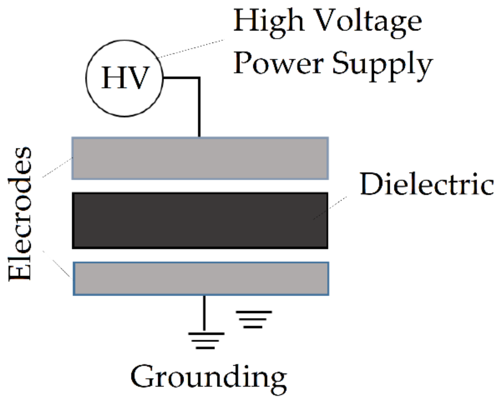
| Dielectric barrier discharge (DBD) systems | high | atmospheric | plasma filamentary discharge cleaning | frequency of 10–104 Hz, a continuous energy source must provide the required degree of ionization | use of high-velocity gas streams to remove cleaning products | [142] |
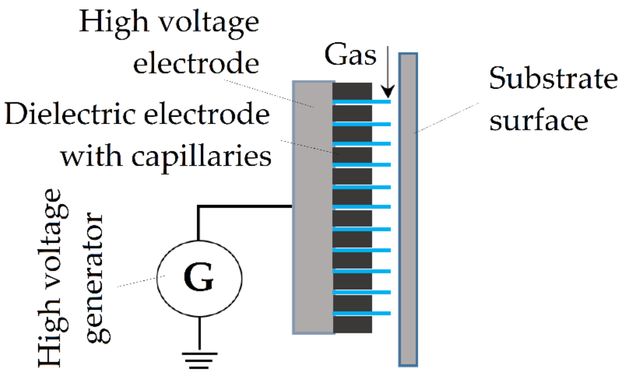
| Capillary barrier discharge | high | atmospheric | plasma cleaning by a filamentary discharge implemented by a device with a dielectric material with a number of small holes | the uniformity of the discharge depends on the location of the capillaries | provides a higher plasma density, the possibility of the appearance of unwanted substances on the substrate | [143] |
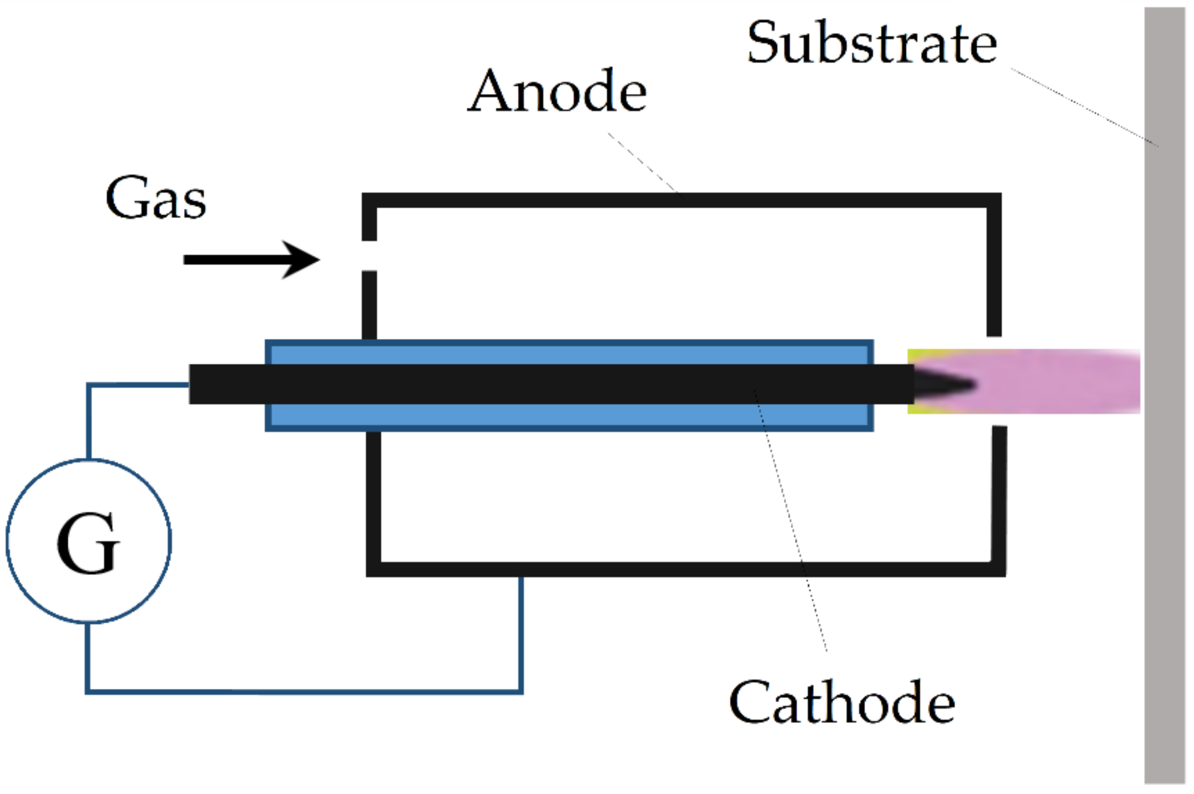
| Corona discharge | high | atmospheric | plasma cleaning and etching | use of a needle (wire) electrode | the addition of oxygen is required for the decomposition of organic contaminants, the possibility of surface oxidation, and the decomposition of cleaning products | [144] |
| use of a planar electrode | ||||||
| High frequency and super high frequency discharges | high | atmospheric | HF-cleaning | the conditions are realized as in the case of a glow discharge; the plasma is generated in He, N2, Helium with the addition of 1–3% gas (O2, N2, H2, or CF4). | high energy efficiency, low temperature | [145] |
| SHF-cleaning | parameters within the arc and atmospheric pressure glow discharge | provides significant heating of the cleaned surface |
Publisher’s Note: MDPI stays neutral with regard to jurisdictional claims in published maps and institutional affiliations. |
© 2022 by the authors. Licensee MDPI, Basel, Switzerland. This article is an open access article distributed under the terms and conditions of the Creative Commons Attribution (CC BY) license (https://creativecommons.org/licenses/by/4.0/).
Share and Cite
Okunkova, A.A.; Shekhtman, S.R.; Metel, A.S.; Suhova, N.A.; Fedorov, S.V.; Volosova, M.A.; Grigoriev, S.N. On Defect Minimization Caused by Oxide Phase Formation in Laser Powder Bed Fusion. Metals 2022, 12, 760. https://doi.org/10.3390/met12050760
Okunkova AA, Shekhtman SR, Metel AS, Suhova NA, Fedorov SV, Volosova MA, Grigoriev SN. On Defect Minimization Caused by Oxide Phase Formation in Laser Powder Bed Fusion. Metals. 2022; 12(5):760. https://doi.org/10.3390/met12050760
Chicago/Turabian StyleOkunkova, Anna A., Semen R. Shekhtman, Alexander S. Metel, Nadegda A. Suhova, Sergey V. Fedorov, Marina A. Volosova, and Sergey N. Grigoriev. 2022. "On Defect Minimization Caused by Oxide Phase Formation in Laser Powder Bed Fusion" Metals 12, no. 5: 760. https://doi.org/10.3390/met12050760