
Additively Manufactured Porous Ti6Al4V for Bone Implants: A Review


1
Department of Industrial Engineering, J.B. Speed School of Engineering, University of Louisville, Louisville, KY 40292, USA
2
Department of Mechanical Engineering, J.B. Speed School of Engineering, University of Louisville, Louisville, KY 40292, USA
3
Additive Manufacturing Institute of Science and Technology (AMIST), J.B. Speed School of Engineering, University of Louisville, Louisville, KY 40292, USA
*
Authors to whom correspondence should be addressed.
Metals 2022, 12(4), 687; https://doi.org/10.3390/met12040687
Submission received: 8 March 2022
/
Revised: 5 April 2022
/
Accepted: 13 April 2022
/
Published: 16 April 2022
(This article belongs to the Special Issue Additive Manufacturing of Metallic Materials: Characterization, Properties, and Modeling)
Abstract
:Ti-6Al-4V (Ti64) alloy is one of the most widely used orthopedic implant materials due to its mechanical properties, corrosion resistance, and biocompatibility nature. Porous Ti64 structures are gaining more research interest as bone implants as they can help in reducing the stress-shielding effect when compared to their solid counterpart. The literature shows that porous Ti64 implants fabricated using different additive manufacturing (AM) process routes, such as laser powder bed fusion (L-PBF) and electron beam melting (EBM) can be tailored to mimic the mechanical properties of natural bone. This review paper categorizes porous implant designs into non-gradient (uniform) and gradient (non-uniform) porous structures. Gradient porous design appears to be more promising for orthopedic applications due to its closeness towards natural bone morphology and improved mechanical properties. In addition, this paper outlines the details on bone structure and its properties, mechanical properties, fatigue behavior, multifunctional porous implant designs, current challenges, and literature gaps in the research studies on porous Ti64 bone implants.
1. Introduction
The history dates to the time of the late 1960s when the first use of porous metal structures in orthopedics was reported, and ever since the use of these products has continuously increased [1]. In the early 1970s, porous metal development experienced several breakthroughs, setting the stage for future in-growth materials in orthopedic surgery. Galante et al. [2] pioneered the development of fiber-metal leading to its clinical use as a porous coating in hip and knee arthroplasty. Simultaneously, works on the sintering process laid the foundation for the porous cobalt-chromium (CoCr) alloy coatings in use today [3]. Most recently, a new series of highly porous metals has been developed and released for use in orthopedic surgery, including porous tantalum, porous titanium (Ti), and their alloys [3]. This increasing trend in reconstructive surgery is apparent as solid metal implants have high stiffness and strength, however, porous implants are optimal for this use as they allow bone in-growth through the open porosities and have an improved fixation due to their high surface roughness. In addition, these porous implants have lower stiffness and prevent stress-shielding [1,4].
According to the Agency for Healthcare Research and Quality [5], more than 450,000 total hip replacements and just under 700,000 total knee replacements are performed annually in the United States. The 60+ years-old group has a global population that is expected to double from 2020 to 2050 due to both overall population growth and an expected increase in life expectancy from 73 to 77 during this period [6]. This continued increase in the elderly age population demands an increase in the efficiency of the orthopedic implant, which lowers implant failure and the need for revision surgery as they add physical, financial, and psychological burden to the patient. Different implant materials including polymers [7,8,9], ceramics [10,11,12,13,14], metals [15,16,17,18,19,20], and their composites [21,22,23,24,25] are currently being tested for manufacturing orthopedic implants. Most metals fall under the bio tolerant category, however, titanium and its alloys in certain conditions are bioinert in nature [26]. Among these implant materials, titanium is the best base material for additive manufacturing of orthopedic implants due to its excellent mechanical strength, natural good corrosion resistance, Magnetic Resonance Imaging (MRI) compatibility, acceptable in vivo biocompatibility, and bio-adhesion [27,28]. Despite these advantages, the presence of a large metallic foreign body creates obstacles such as promotion of chronic inflammation, leaching, infection and biofilm formation [29].
Titanium implants form protective layers of titania (TiO2) that are a few nanometers thick when exposed to air/water [30,31]. Toxicological concerns such as yellow nail syndrome arise when any damage to this layer occurs as a result of aggravated leaching of debris and nanoparticles from Ti implants [30,32]. These leached Ti particles in surrounding tissues can range between 10 nm to 30–60 µm and the average concentration of locally leached Ti ions are 205–210 ng per mg of the implant’s weight [30,33,34]. This phenomenon is more severe in the sintering-based AM process where consolidation of powder occurs below the melting point and results in disintegration/weakening of the implant structure over time, along with the release of Ti particles [35]. The release of these Ti particles has long term adverse effects such as allergic reactions, mutagenesis, carcinogenicity and hypersensitivity reactions, which ultimately result in implant rejection [32,35,36].
Among Ti alloys, commercially pure titanium (CP-Ti) and Ti64 are the most preferred Ti alloys for orthopedic implants [37,38,39]. However, due to the stress-shielding effect of the solid Ti, the research focus has shifted towards the porous Ti alloys implants. Additive manufacturing of porous Ti64 orthopedic and spinal implants with complex porous geometries is often used to achieve their osseointegration properties [40]. The bone implants are expected to have: 1. Good biocompatibility; 2. Appropriate pore sizes and porosity, which are suitable for bone cell infiltration and growth; 3. Comparable mechanical properties with adjacent bone tissue; 4. Osteoconductivity and osteoinductivity; and 5. Biodegradability, such that no traces of the original prosthesis are found after bone healing without any side effects of the degradation products on the human body [41].
The long-term clinical success of bone implants requires the fabrication of porous structures with consideration of elastic modulus, compressive and fatigue strength, wear hardness, and corrosion resistance properties together with biomaterials and biomedical engineering aspects [42]. The research focus on implants is given to specific clinical challenges, such as stress-shielding and osseointegration [43]. Furthermore, for load-bearing applications, the key focus is on maximizing osseointegration to minimize the risk of aseptic loosening as around 20% of orthopedic revisions within two years are associated with loosening. The market of these implants can be broadly divided into mass manufactured and patient-specific implants. Mass-manufactured implants and their mid-term outcomes are currently positive, however their long-term outcomes are still needed to illustrate additional clinical benefits. Patient-specific or “custom” implants are used where no alternative implant exists, and its use is justified through the last resort where the benefits outweigh the risks [43].
Studies on the effect of regular, irregular, fully random, and several types of unit cell structures on mechanical properties of AM manufactured Ti64 implants are available [44,45,46]. The results from these studies show that specimens with higher porosity tend to buckle. Strength and Young’s modulus were found to be decreased with increasing porosity and pore size. Hanks et al. [46] developed a graphical user interface to provide Ashby-style plots for unit cell selection of the AM lattice structure that helps to understand the relationship of the unit cell topology and the lattice structure’s mechanical properties, with the intent of guiding appropriate unit cell selection. Furthermore, research on the modification of porous structure unit cells, such as diamond-shaped (tetrahedral) lattice cells, for better integrity of mechanical properties can also be found [47]. Similarly, the topological design of lattice structures, which includes beam-based unit cells, sheet-based unit cells, and functional gradients, can be rationally designed to achieve the desired properties including mechanical, fatigue, mass transport, (e.g., permeability, diffusivity), surface area, and geometrical features, while the rate of tissue regeneration, e.g., surface curvature, are simultaneously optimized [48]. Furthermore, changing the type of unit cell in the porous structure can result in very different mechanical properties for the same porosity level [49]. Comparing the normalized, i.e., the ratio of a property in the porous structure to that of the bulk material, mechanical properties of porous non-gradient Co-Cr structures with mechanical properties of non-gradient Ti64 and pure Ti with the same unit cell designs, Hedayati et al. [50] found that topological design can cause up to a ten-fold difference in mechanical properties of AM porous structure, while up to two-fold difference when changing the material type. This indicates the usefulness of bulk material properties as scale factors to convert normalized mechanical properties of porous non-gradient structures to their absolute values.
In recognition of the benefits of utilizing AM for manufacturing orthopedic implants, review articles on AM used for metallic implants [41,43,51,52], porous metallic implants [48,49], biodegradable porous metallic implants [15], and common AM implants [26] are also available. Among the metallic implants, a systematic review on titanium and its alloys can be found [27,37,53,54]. However, review articles with focus areas only on the AM manufactured Ti64 are rarely available. Besides, the review on the fatigue behavior of the porous implants appears to be barely discussed in most of the orthopedic implants review articles. Ti64 being the most preferred titanium alloy for orthopedic applications and porous structures design is the prime focus of many recent orthopedic implants/scaffolds’ studies. An article by Aufa et al. [38] focused on the Ti64 biomedical implants manufactured using only a laser powder bed fusion-selective laser melting (SLM) process. The mechanical properties and the effects of surface treatment and surface modification of SLM Ti64 implants were reviewed, however the review on the fatigue behavior of these porous implants is completely missing. Even within the L-PBF process, selective laser sintering (SLS) is also used for generating porous Ti64 implants. In addition to L-PBF, studies on porous Ti64 implants manufactured using electron beam melting, direct write process and Laser Engineered Net Shaping (LENSTM) are widely available. Therefore, there exists a significant gap in the literature availability on porous Ti64 implants, which includes all the AM processes that are used for biomedical applications. On the other hand, Spece et al. [40] performed a systematic review on preclinical in vivo testing of 3D printed Ti64 porous orthopedic implants. Although, this review provides decades of experience and lessons learned with AM porous Ti64 implants, many novel research works have been performed on AM porous Ti64 where no in vivo testing was carried out and thus there is a need for a review that includes those in vitro, porous designs, mechanical, fatigue, multifunctionality properties, etc., of AM porous Ti64 implants/scaffolds.
With the aim to fulfill the review literature gap, this paper aims to provide in-depth knowledge and information on recent advancements of porous Ti64 implants from different perspectives: design, mechanical properties, fatigue behavior, and multifunctionality. All the processes utilized in the additive manufacturing of the porous Ti64 bone implants are reviewed and are presented in a detailed fashion to provide proper guidance for future research in the design and development of functionally porous Ti64 implants/scaffolds. The orthopedic implant is regularly subjected to loading condition and the porous implant design with its porous structure is more prone to fatigue failure as compared to its counterpart. Thus, this paper has dedicated a sub-section for the fatigue behavior of the AM porous Ti64 structures such that the existing review gaps on their fatigue behavior are addressed. Moreover, the novelty of this review comes from the holistic overview of different AM processes used in the design and development of porous Ti64 implants/scaffolds from design, process, physical, mechanical, fatigue, biological and multifunctionality perspectives. In this article, porous implant designs are classified into non-gradient and gradient porous structures. Due to its greater resemblance to natural bone morphology and improved mechanical properties, gradient porous design appears more promising for orthopedic applications. Furthermore, the human bone properties and structure, mechanical properties of porous Ti64, as well as multifunctional porous implant designs, their limitations, current challenges, and unresolved literature gaps are thoroughly discussed later in the paper.
2. Methodology
To find the literature related to this topic, keywords such as “additive manufacturing of porous Ti6Al4V bone implants”, “porous bone implants”, “fatigue behavior of porous Ti6Al4V bone implants”, “leaching of titanium implants” etc., were used in online searching tools including web of science, google scholar, MDPI and ScienceDirect websites. The papers were always listed based on the descending order from the recent published date. For each section/sub-section, significant papers were selected and reviewed. More focus was given to recently published papers, i.e., after 2015. Key findings from these reviewed articles were analyzed and compiled to write this paper.
3. Bone Structure, Its Properties, and Bone Healing Mechanism
3.1. Bone Structure
Bones are categorized into two major groups, namely cortical bones, and cancellous bones. Cortical bones are compact bones and are responsible for providing mechanical strength, structural rigidity, and movement. They account for 80% of the mass of the bones in the human body. Cancellous bones, also known as trabecular bones, are soft, spongy bones and are responsible for providing structural support to the cortical bones, flexibility, and reduction in weight. Most of the active functions including blood cell production and ion exchange take place in the trabecular bones. They account for roughly 20% of the total mass of the skeleton. From the porous structure perspective, cancellous bone has porosities between 50% and 90%, whereas cortical bone has a porosity less than 10% [41].
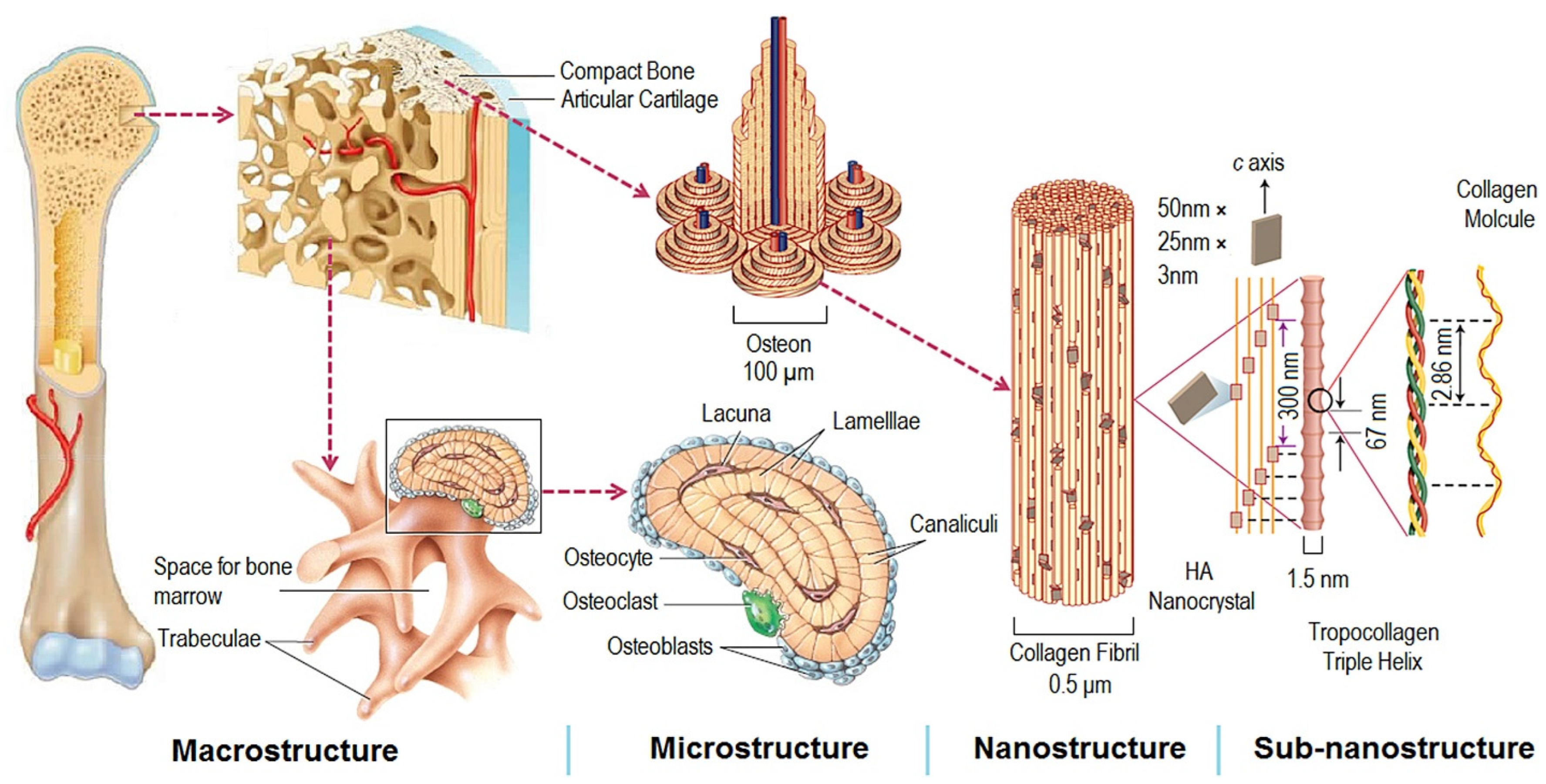
The natural bone acts as a heterogeneous and anisotropic nanocomposite [55], of which the principal components are organized hierarchically into several structural levels, from macro to the nanometer scale as shown in Figure 1.
Macroscale arrangements of the bone involve both compact/cortical bone at the surface and spongy/trabecular bone (foam-like material with ~100 µm thick struts) in the interior. Compact bone is composed of Osteons and Haversian canals, which surround blood vessels. Osteons have a lamellar structure, with individual lamella consisting of fibers arranged in geometrical patterns. The fibers comprise several mineralized collagen fibrils, composed of collagen protein molecules (tropocollagen) formed from three chains of amino acids and nanocrystals of hydroxyapatite (HA) and linked by organic phase to form fibril arrays [55].
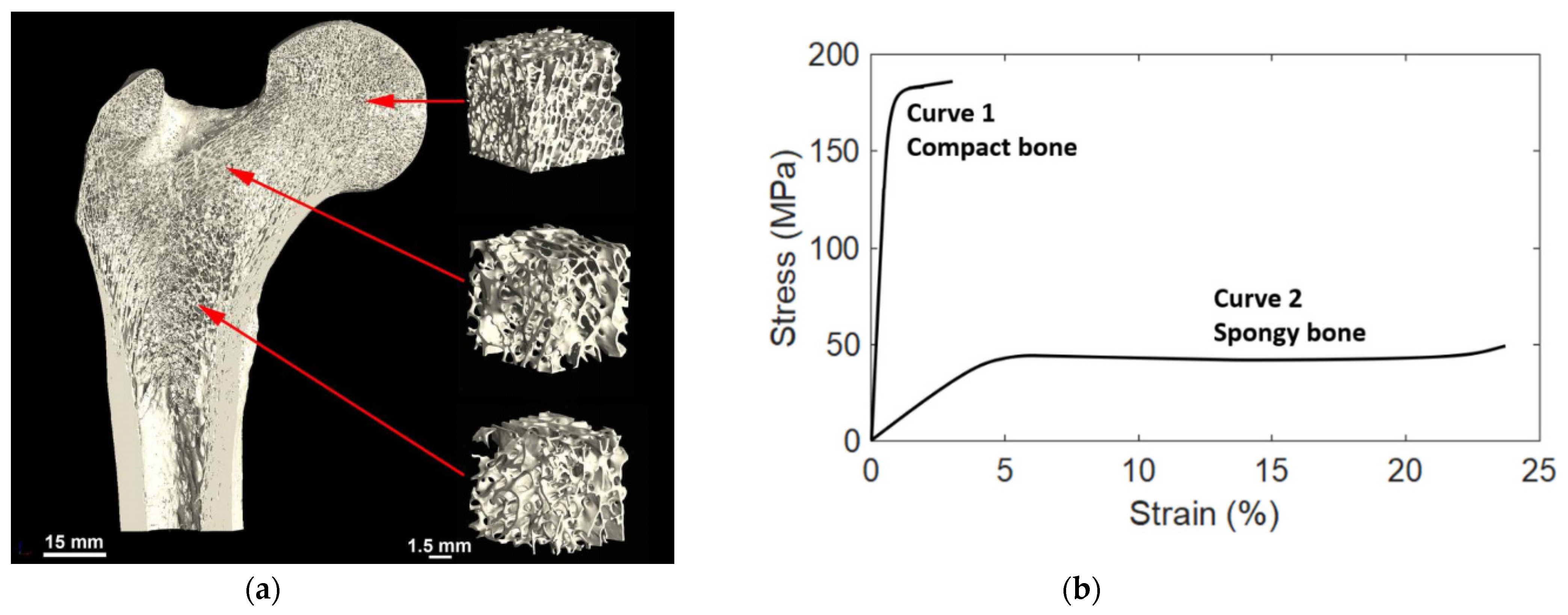
The cortical bone thickness and the density and pore structure of the trabecular bone may vary significantly by location in the body and even within one bone, depending on the local requirements. Near the joints the trabecular bone is denser due to varying mechanical load requirements (strength and angles of loading), while in the central part of the bone there is less dense and less isotropic trabecular bone, which is more directionally aligned as shown in Figure 2a.
3.2. Mechanical Properties
Figure 2b shows a load-deformation curve for a specimen of hydrated bone loaded in tension [58]. The bone follows the normal load-deformation trend for that of metals. First, there is a rising part where the load is proportional to deformation. At the yield point, the situation changes, and the curve becomes much flatter. With a slight increase in load, there is a substantial increase in deformation. Then the specimen breaks. This load-deformation curve can be normalized and turned into a stress-strain curve. The total area under the curve is the amount of energy per unit volume that a material can absorb before rupturing, also known as the material toughness.
Cortical Bone: The Modulus of Elasticity of cortical bone is about 15 GPa. At the yield point, the stress is 120 MPa, and the strain is 0.008. Table 1 gives some representative values of the mechanical properties of cortical bone loaded along the length of the bone. This is an approximation table, but gives some guidance as to the properties and their potential range.
Cancellous Bone: Cancellous bone is soft bone. The bone does not form closed cells, so the bone, and the marrow, are always interconnected. The Young’s modulus of such bone is as low as 1.9 GPa and can go up to 6 GPa [58].
3.3. Bone Healing Mechanism
Most of the fractured bone goes through the same healing process or recovery mechanism. This holds true for the bone whether it has been operated on during the surgical procedure or fractured by being involved in an accident. Usually, the bone healing mechanism experiences an overlap of three stages, namely inflammation, bone production, and bone remodeling [59], as described below:
- Inflammation is the first step of the healing mechanism, and this starts right after the bone breaks. After the bone fractures, the blood vessels’ connections in the bone are also ruptured and this results in bleeding into the fractured area. This process is called inflammation where the blood starts to clot in the fractured site and swelling is observed. Inflammation lasts for several days and thus provides the initial framework and stability to the fractured bone for developing new bone;
- The bone production step follows the inflammation step in the healing process. The clotted blood from inflammation is gradually replaced by the growth of soft callus cartilage and fibrous tissues. Eventually, when healing progresses, this soft callus cartilage is replaced with hard bone known as a hard callus. This bone is thus detectable by x-rays afterward;
- Bone remodeling is the final phase of the healing process and could last for weeks or several months. The hard callus bone continues to form and becomes compact, returns to its original shape and form, ruptured blood vessels grow, and blood circulation improves in the area. Sufficient healing of the bone after several weeks gradually remodels the bone for usual weight-bearing activities such as standing and walking, and it provides necessary support to the structure [60]. More importantly, the loading magnitude and loading frequency have significant effects on bone remodeling and thus have a major impact on the bone healing process [41].
In addition, the implant-bone healing process can be briefly summarized in the following five stages: (1) primary implant fixation; (2) blood-implant contact; (3) platelet activation and coagulation; (4) inflammation and angiogenesis; and (5) bone formation [61].
3.4. Hindrance for Bone Healing
A wide variety of factors can slow down the healing process of a fractured bone. Movement of fractured bone fragments and weight-bearing too soon delays bone formation. The implant must be securely fixed to the host bone such that osseointegration is not inhibited. The interactions between the implant and the proteinous monolayer create the basis for osseointegration and ossification (bone formation) and are crucial to the proper healing of the wound, and ultimately, successful implantation [60,61]. In addition, smoking, medical conditions, such as diabetes, hormone-related problems or vascular disease, some medications, such as corticosteroids and other immunosuppressants, severe and complicated fractures, old age, poor nutrition or impaired metabolism, and low levels of calcium and vitamin D all hinder bone healing.
3.5. Need for Porous Structure and Its Advantages
Implants are made from biomaterials and their alloys. These materials, compared to bone, have a very high modulus of elasticity. It is well known that the stress transfer between an implant and a bone is not homogeneous when Young’s moduli of the implant and the bone are different; this is defined as stress shielding. In such conditions, bone atrophy occurs and leads to the loosening of the implant and refracturing of the bone. Therefore, it is desirable if the stiffness (Young’s modulus) value is as close as possible to that of the bone [62].
Porosities in the bone implants have two (2) major advantages:
- Provide space and 3D structure for bone ingrowth.
Based on the literature reviewed in this study, the porosity ranging from 25% to 90% and pore size ranging from 200 µm to 1500 µm were found to be mostly used in the design of porous Ti64 implants. During the porous implant design, often there exists a trade-off between the porosity percentage and mechanical strength. An increase in mechanical interlock strength of a porous implant can be observed through osseointegration, however a design with porosity greater than 80% results in a decrease in both strength and bone ingrowth [64]. Proper tailoring of porosity percentage, porosity gradient and its direction, and transition region height are required such that the biomimetic implant design can be possible without compromising the mechanical properties requirements, especially porous implant strength.
The premise of bone ingrowth is that cells adhere to the surface of materials and migrate to the inner space, thus porosities play a vital role in bone tissue engineering as it facilitates the ingrowth of mineralized tissue into a porous network. It is also suitable for seeding cells, delivering drugs, capillary tissue action, and osteoprogenitor cell migration [48,65].
In this study, we have focused on Titanium alloy, namely Ti64. This is an alpha-beta titanium alloy, which has excellent corrosion resistance to chlorides, seawater, and sour and oxidizing acid media, and acts as an ideal candidate for orthopedic and dental implants [66]. The biocompatibility with living tissues and the high strength-to-weight ratio of Ti64 alloy make it an ideal candidate for bone implants. Furthermore, Ti64 shows good osseointegration property, which is defined as the functional bone adherence property where a new bone is laid down directly on the implant surface and helps the implant to exhibit mechanical stability [67,68]. More importantly, Ti64 alloy also has a low modulus of elasticity, which is roughly half that of steel and nickel alloys, making it more similar to bone in terms of mechanical properties [66]. Further, the bioinert and biocompatible nature of Ti64 with spontaneous formation of oxide layer ensures its stability in the body after implantation [69].
Titanium is generally non-magnetic in nature, generating insignificant forces in a strong magnetic field, and is considered safe to be present in clinical MRI systems. However, it has weak paramagnetic property and becomes magnetized within the MRI field resulting in either a loss of signal or distortion in the MRI image (known as susceptibility effect) due to changes in magnetic field from the presence of Ti64 implant [28,70]. This effect limits the use of MRI to visualize the tissue surrounding implants hindering future investigations in the region or diagnosis of post-operative complications. AM porous structures may be an upstream method for reducing susceptibility artifacts in Ti64 implants, helping in improving post-operative diagnosis capability [28].
4. Porosity Designs
Porous implant structures involve porosity, pore size, etc., as major morphological design parameters [71]. The level of these factors has a significant impact on the mechanical and biological properties of the implants. The impact of these factors can be found in the literature. Some of the papers on these studies are listed in Table 2, Table 3 and Table 4. Bone implant porosity and stiffness/strength require optimized trade-off to improve long-term load sharing while simultaneously promoting osseointegration [64]. Porous Ti64 implants have been developed with a biomimetic design attempt towards natural bone morphology. The porous Ti64 implants can be categorized into non-gradient and gradient porous implants. Non-gradient implant design has uniform porosity throughout the implant structure, whereas the gradient design may have porosity variation along x, y, and/or z-direction. Details on these porosity design types are explained later in this section. During the literature review, most of the studies on porous design were identified to be performed on samples fabricated by Laser Powder Bed Fusion (L-PBF) and Electron Beam Melting (EBM). Furthermore, some pieces of literature were found on porous Ti64 alloy implants fabricated using direct ink writing (DIW) and Laser Engineered Net Shaping (LENSTM) processes. In the powder bed fusion (PBF) process, the parts are fabricated by heating powder particles at selective areas until they are sintered or melted. Based on the source of energy utilized, PBF can be categorized into laser powder bed fusion or electron beam melting. In the DIW process, two-dimensional or three-dimensional structures are created directly onto the flat or conformal surfaces through jetting or dispensing, or extruding of material such as the micro-dispensing of ink. LENSTM is an example of directed energy deposition (DED) AM process. The DED process is mostly used for part repair where the material is deposited mostly on the existing substrate to generate new surfaces by using powder feedstock or wire feedstock. LENSTM, originally developed by Sandia National Labs in 1996, uses Nd: YAG/fiber laser to melt co-axially delivered powder feedstock and deposits the material into the substrate.
The evaluation of L-PBF and EBM AM process conditions are most commonly performed using volumetric energy density, defined as [72]:
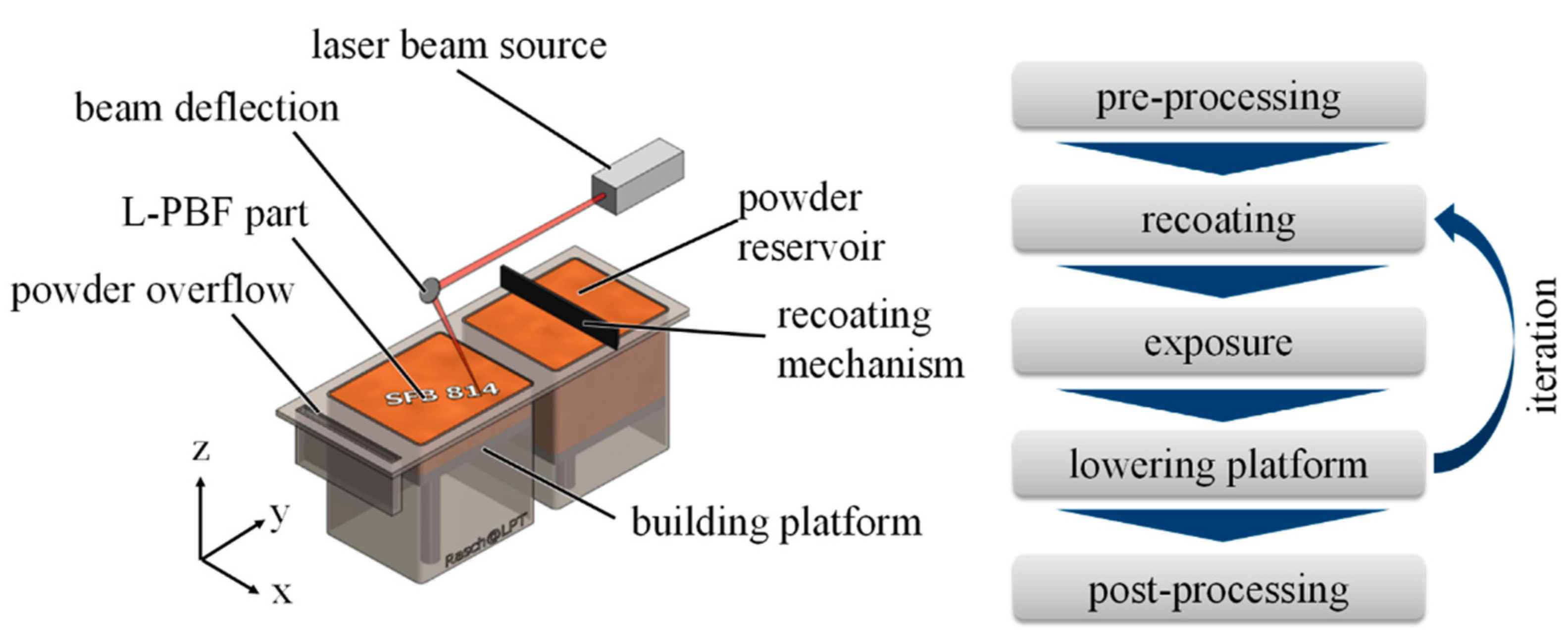
where P is the laser/electron beam power, v is the scan speed, h is the hatch distance, and d is the layer thickness. The PBF process takes place inside an enclosed chamber filled with inert gas to minimize degradation and oxidation of powered material [73]. First, a layer typically 0.1 mm thick of powder material is spread over the build platform. The powder is then preheated and maintained at an elevated temperature below the melting point or glass transition temperature of the powdered material. A focused heat source (laser or electron beam) is then directed onto the powder bed and is moved using galvanometers in a way that it thermally fuses the material to form the slice cross-section completing the first layer. In this process, the energy beam is scanned over the powder surface (scan speed) often in a hatched stripe pattern (hatch distance) using controlled mirrors until a layer is processed. After completing this layer, the build platform is lowered by one layer thickness, and a new layer of powder is spread over the build platform using a recoater blade mechanism. The heat source again scans the subsequent slice cross-section. This process repeats until the complete part is built. Finally, the part is removed from the powder bed, loose powders are cleaned off the part, and further finishing operations, if necessary, are performed [73]. The schematic of the PBF process is shown in Figure 3. A study of the effect of laser processing parameters showed that mechanical properties increased with increases in either laser power or exposure time [44]. Furthermore, the surface topography and roughness of implants manufactured using L-PBF and EBM are affected by build orientation [74,75]. The lowering of the build angle lowers surface roughness and hydrophobicity, and the number of partially melted particles [75]. This reduction is reported to be directly correlated with significantly lower biofilm coverage for a lower build angle without compromising cell viability and attachment. Since the porous AM implants (both gradient and non-gradient) have struts and walls oriented at different angles, they may require careful consideration during the design for biofilm restriction. A review article by Aufa et al. [38] states that a rough surface (Ra values) of 3 µm–5 µm is favorable for osteoblasts attachment both in vivo and in vitro, and an implant roughness between the 1 µm and 2 µm range is effective for developing a titanium dioxide (TiO2) layer that is resistant to bacterial infection.
4.1. Non-Gradient (Uniform) Porous Structure
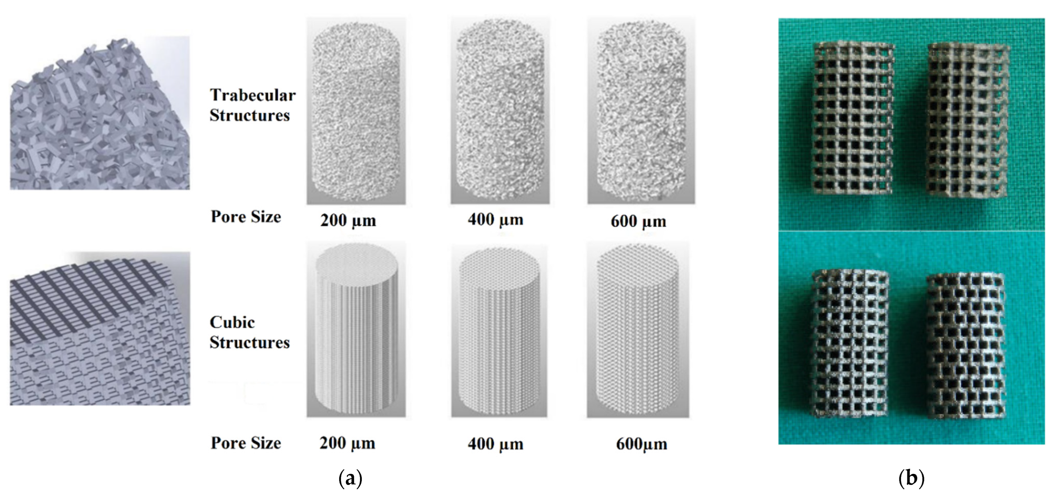
One of the major design parameters of bone implants is porosity. Non-gradient or uniform porosity is one of the porosity design parameters where the size of pores does not change throughout the implant. This makes the implant density uniform along x, y, and/or z-direction. Figure 4 and Figure 5 represent some of the non-gradient porous structures found in the literature [77,78,79,80,81]. The design optimization study on uniform Ti lattice structure by El-Sayed et al. [82] identified the most significant design parameter to be strut length where the porosity of unit cell increased with increasing length, but the effect reverses on strength and elasticity. Goto et al. [83] studied two different designed implants: one with a smooth surface without any porosity and the other with uniform pores of 800 µm and 1400 µm. The characterization of these EBM fabricated porous implants showed average porosity of 57.5% from binary images of 30 slices. Balci et al. [84] obtained bone samples from the femoral and vertebral regions of a sheep, scanned them using Micro-CT and produced trabecular bone models with two different porosities with the purpose of increasing biocompatibility by imitating bone. The vertebra model had a distribution between 102 µm and 1719 µm, and the femur model had a distribution between 90 µm and 1434 µm. Ødegaard et al. [77] manufactured scaffolds with 800 µm void spacing and lattice thickness based on the Schwarz P triply periodic minimal surface-based unit cell and had a designed porosity of 50%. Biomimetic porous Ti bone scaffolds with a high level of interconnectivity between pores are beneficial for tissue growth and osseointegration [85]. Tsai et al. [86] used a highly interconnected pore network structure with a high-volume porosity of 60% for better bone growth. Fluid permeability is a function of pore characteristics (i.e., pore shape, size, and porosity) and shows a strong correlation with bone ingrowth and thereby served as an indication of scaffold osteointegration capabilities [87,88]. Accordingly, Arjunan et al. [88] investigated the uniform porous L-PBF scaffold designs with targeted porosity of 68.46%–90.69% considering permeability, stiffness, strength, and stress concentration factor. The results showed the primary dependency of maximum stress on pore shape rather than relative density. Required stiffness and strength of bone scaffold can be achieved by tailoring the stress concentration factor, irrespective of the targeted porosity. Therefore, in addition to porosity, pore shape and permeability, the stress concentration should also be carefully considered during the design of functional porous scaffold.
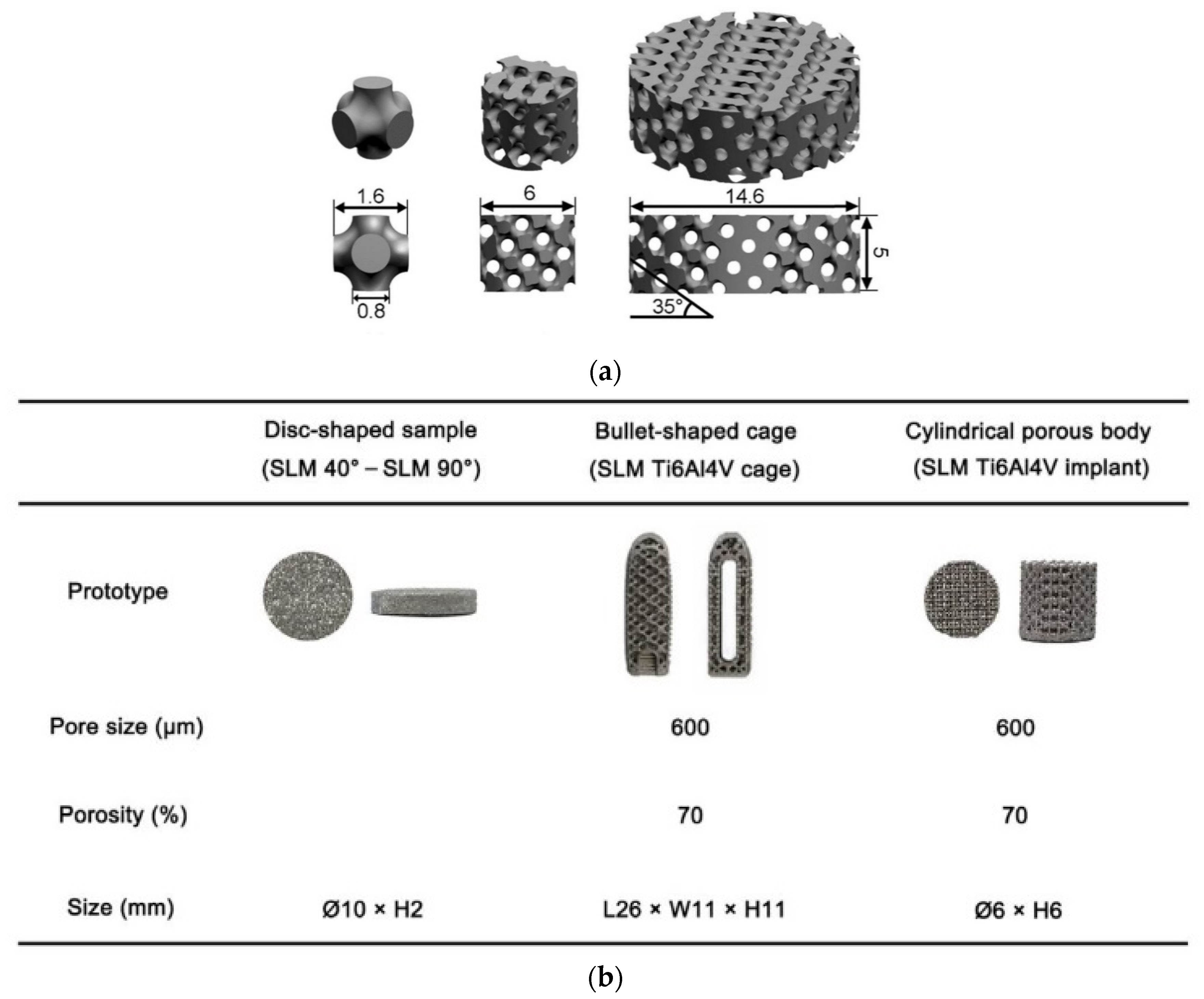
The porous Ti64 cage was produced by the L-PBF (Selective Laser Melting, SLM) process. Chen et al. [78] performed a study on three different shapes of Ti64 samples with a porosity of 70% and a pore size of 600 µm as shown in Figure 5. In the study by Hameed et al. [89], the decrease in mechanical strength with an increase in pore size was identified and a scaffold with a pore size of 250 µm showed the optimum combination of overall mechanical and biological properties for practical applications. Zhang et al. [90] studied the spacing of the laser scan lines (hatch spacing) on pore characteristics and set the scan line spacing from 200 µm to 700 µm by a step size of 100 µm to produce the porous implants. Ahmadi et al. [67] investigated the effects of two different heat treatment regimens (below and above β-transus) on the mechanical properties and microstructure of porous Ti64 specimens. Many similar studies on the uniform gradient porous Ti64 can be found in the literature. Among them, some of the significant articles are listed in Table 2.
Figure 4.
(a) Different models of porous samples, the first row of three images shows trabecular structures with different pore sizes, whereas the second row shows cubic structures with different pore sizes. Reprinted with permission from ref. [79]. 2021, MDPI. (b) Photographs of 3D scaffolds with identical strut design in x-z and y-z plane (above) and shifted strut orientation (below). Reprinted with permission from ref. [80]. 2012, MDPI.

Figure 5.
(a) CAD models of scaffold manufacturing, all measurements are in millimeters. Reprinted with permission from ref. [77]. 2021, Springer Nature. (b) Different SLM-fabricated samples along with their parameters. Reprinted with permission from ref. [78]. 2022, Springer Nature.


Table 2.
Mechanical Properties of Non-Gradient Porous Structure.
| Author | Process | Porosity Design | Strength (Compressive/Tensile) | Young’s Modulus | Other Findings |
|---|---|---|---|---|---|
| Li et al. [65] | EBM | Porous scaffolds with three pore sizes (300~400, 400~500, and 500~700 μm) with porosity of 80% Measured pores size: 315, 485, and 574 μm, respectively; Measured Porosity: 33.8, 50.9, and 61.3%, respectively. | Compressive Strength: 115.2–33.1 MPa | 3.7–1.7 MPa | In vivo study on Goats for 3, 6, and 12 months identified that depth of bone ingrowth increased over time and no implant dislocation was observed; Porous Ti64 scaffold with an intended pore size of 300 to 400 μm are most suitable for cell adhesion and proliferation. |
| Melancon et al. [71] | L-PBF | Tetrahedron and Octet -truss unit cells were studied over the entire design space, which includes porosity, strut thickness, unit cell size, pore size, height, width, and depth. | Depend on the unit cell design parameter | Depend on the unit cell design parameter | Proposed a systematic approach integrating computed tomography, mechanical testing, and statistical analysis of geometric imperfections to generate statistical-based numerical models of high strength additively manufactured porous biomaterials; The proposed methodology reduced the error between predicted and tested mechanical properties from 49% to 11% (elastic modulus) and 41% to 7.6% (yield strength) |
| Ødegaard et al. [77] | EBM | P TPMS lattice at 35° angle Lattice- and pore diameter: 800 µm Designed porosity 50% | N/A | N/A | qPCR analysis suggests that the BMSCs differentiated into osteoblasts; Staining of alkaline phosphatase at day 7 and calcium deposits at day 28 suggest bone matrix is mineralization. |
| Chen et al. [78] | L-PBF | Bullet-shaped cage and Cylindrical porous body with a designated pore size of 600 µm and porosity of 70%. In vivo Test Subject: Beagle dogs | Bullet-shaped cage: Compressive Strength = 94.7 MPa at 0.29% strain | Bullet-shaped cage: −0.51 GPa | Bullet-shaped cage showed mechanical properties comparable to commercial PEEK cage; Cylindrical porous Ti body and commercial tantalum implant (casting Ta implant) with same porosity and pore size exhibited similar bone ingrowth at 4 and 12 weeks; Great potential of L-PBF-fabricated porous Ti64 cage as spinal fusion implant |
| Hudak et al. [79] | L-PBF | Pore size: 200, 400 and 600 µm Structure: Cubic and Trabecular | Tensile: 302 ± 8.09 to 1631.08 ± 41.49 MPa | 3.80 ± 0.42 to 10.50 ± 0.58 GPa | Yield: 198.45 ± 83.29 to 1055.03 ± 135.90 MPa; 200 µm and cubic structure |
| Wieding et al. [80] | L-PBF | 3 different scaffold designs with 70% porosity D1—struts with a rectangular cross-section (CS), vertical orientation, width: 400 µm, height: 800 µm D2—struts with rectangular CS, vertical strut shifted half the strut height in the x-z plane D3—orientated diagonally to vertical axis and exhibited circular CS | Compressive Strength (MPa) D1: 155 ± 7 D2: 145 ± 2 D3: 164 ± 6 | (GPa) D1: 5.1 ± 0.3 D2: 3.7 ± 0.2 D3: 6.7 ± 0.3 | Ultimate Compressive Strain (%) D1: 5.22 ± 0.34 D2: 6.70 ± 0.56 D3: 3.45 ± 0.50 |
| Balci et al. [84] | L-PBF (Ti64 ELI) | Vertebra: Size—102 to 1719 µm Average diameter—767 ± 264 µm Femur: Size—90 to 1434 µm Average diameter—624 ± 245 µm | N/A | N/A | Bone structure successfully imitated at 1:1 and 1:1.25 productional scales |
| Tsai et al. [86] | L-PBF | Pore size below 500 µm Volume porosity 60% | N/A | N/A | Implants with Ti64 cages compared to Ti and Ta implants— - More pronounced volumes of new bone - Higher crystallinity volumes - High-quality bone formed |
| Coffiginez et al. [91] | DIW | Macro- and micro-interconnected porosity network (42.7% total porosity, which is made up of 34.5% macropores and 8.2% of micropores) Strut Size: 710 µm; Pores Size: 1492 µm | Compressive Strength: 700 MPa | 28–30 GPa | Yield Strength: 265 MPa Implant printable using low-cost printers with 25 wt.% Pluronic F-127 hydrogel loaded with 50 vol. % Ti64 powder particles; Partial sintering at 1200 °C showed an interconnected network of micronic pores within struts; Good proliferation of osteoblast-like cells on scaffolds with loaded Ti64 powder |
| Kan et al. [92] | EBM | Custom-made augment based on 3D reconstruction bone model Human Test Subject Mean Porosity: 61.3 ± 0.4% | N/A | 1.7 ± 0.2 GPa | Thin-layer CT and 3D reconstruction bone models are effective in evaluating periprosthetic bone loss preoperatively; Effective reconstruction of periprosthetic bone defect and restoration of knee prostheses; Stable Protheses even after 3 years. |
| Umar et al. [93] | L-PBF | Stochastic porous lattice structure tested in uniaxial compression in 10 load orientations relative to the structure | N/A | N/A | Modified stochastic lattices have a similar stiffness to cancellous bone and have controllable anisotropy. Standard deviation of Young’s modulus: 52.5 MPa–95.9 MPa |
| Elsayed et al. [94] | DIW | Filament diameter—800 µm Spanning a distance of 1200, 1600, and 2400 µm in X-Y direction and 600 µm height in Z direction resulted in different pore sizes and porosities | N/A | N/A | Total porosity (vol%) of 800 × 400: 53.0 ± 4.7 800 × 800: 58.8 ± 4.2 800 × 1600: 68.1 ± 4.4 |
| Soro et al. [95] | L-PBF | Porous structure based on Schwartz primitive unit-cell and three designed porosity levels: 25%, 42%, and 64%. Strut Size: 500 μm–700 μm Pore Size: 250 μm–700 μm | N/A | 14.3–36.1 GPa | Yield Strength: 86 MPa–319 MPa; 25% wt.% tantalum concentration reduces the weight, cost and lowers the intrinsic elastic modulus of the implants; Significantly higher ductility of implants, which is desirable for surgical handling and enhanced adaptability of implants |
4.2. Gradient (Non-Uniform) Porous Structure
Although non-gradient porous implant structure tends to mimic the natural bone in terms of mechanical properties, the non-gradient designs do not structurally mimic the natural bone morphology. Looking at an example of the human tibia bone, it consists of an outer cortical bone with relatively higher density and inner cancellous bone with lower density. This density variation implies higher mechanical strength at the outer cortical when compared to inner cancellous bone [96]. The variation in bone structure is not only in the radial direction but also along the longitudinal direction. Serious bone density variation in bones such as mandible and vertebrae require the implant to meet these bones’ Young’s modulus to prevent stress shielding. Thus, in vivo implantation of non-gradient porous structures can still be susceptible to serious stress shielding effects [97]. Therefore, to account for these structural differences and inhomogeneity of the natural bone, gradient porous structure designs can be achieved through average porosity % level variation along the longitudinal direction (longitudinal gradient porous structure) and/or the radial direction (radial gradient porous structure) [96,97], as shown in Figure 6. Spatial variation in porosity of gradient lattice structures changes the stiffness and makes it comparable to cortical or trabecular bone, however, the relationship between the mechanical properties and biological properties of the gradient structure is not quite clear [98].
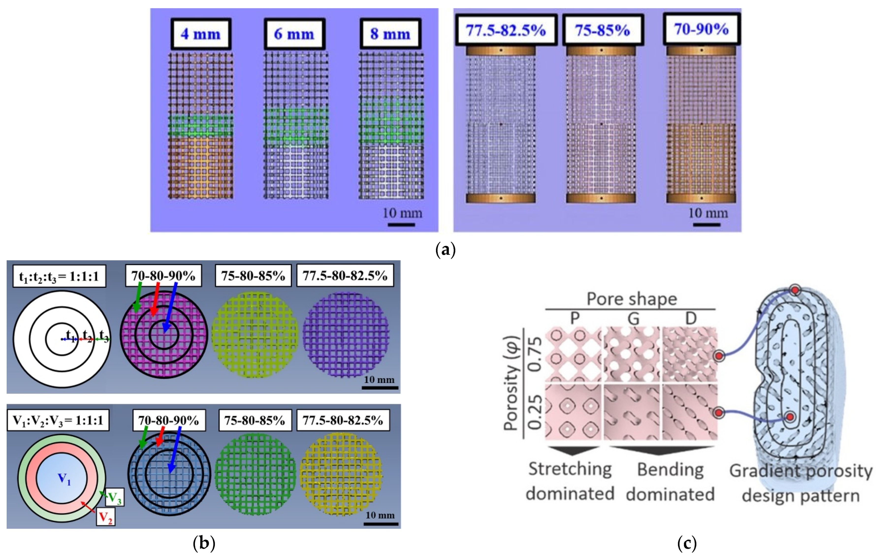
Compared to longitudinal gradient structures, radial-gradient structures appear to have a higher mechanical strength as the outer region with lower porosity protects the inner region to avoid destructive localized deformation [96,97]. Furthermore, even within the radial-gradient design, different unit cell structures (Figure 6c and Figure 7) [99], region thickness, and region volume fraction [96,97] can significantly impact the mechanical properties of the gradient porous implant. For radial design, interestingly, mechanical properties of gradient structures with the same thickness regions increase with an increase in the average porosity percentage level variation, whereas mechanical properties remain approximately the same for gradient porous structures with the same volume regions. Wu et al. [97] showed that the gradient porous structure with transition region is superior to those with a sharp interface in terms of mechanical properties such as Young’s modulus, yield strength, and maximum compressive strength. Furthermore, the failure of samples with transition region occurs towards the higher porosity region as opposed to the interface in sharp interface samples [96]. Another study conducted by Wu et al. [96] found that Young’s modulus, Yield Stress, maximum compressive strength, and strain at failure values of radial gradient samples were within the individual single porosity non-gradient samples values, however, the elastic limit was significantly lowered as a downside. Studies with both radial and longitudinal designs combined into a single porous structure will be an interesting topic of study as these designs will better mimic the natural bone. Additionally, the topological design of functionally graded porous structures exhibits superior comprehensive mechanical properties to uniform porous structures by a combination of low density, moderate Young’s modulus, high yield stress, high maximum stress, and favorable ductility [100].
Figure 7.
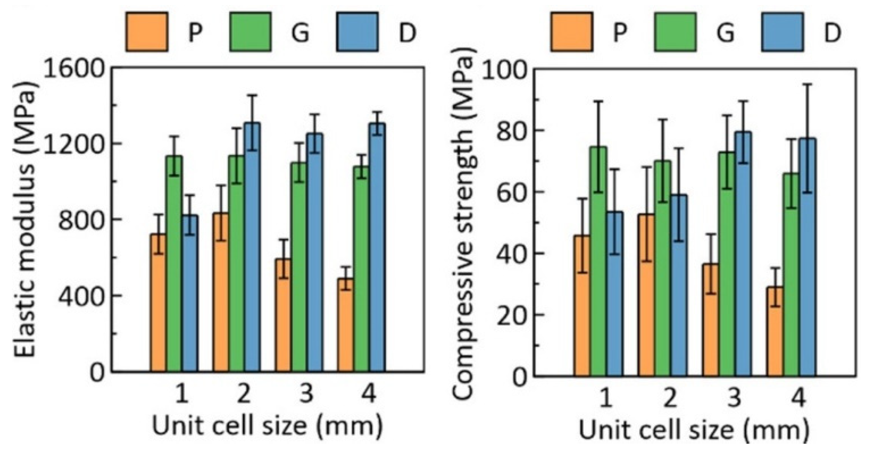
Characterization of the cubic porous scaffolds under compressive loading. Elastic modulus and compressive strength resulted from the stress-strain curves for samples with 0.75 porosity. Reprinted with permission from ref. [99]. 2021, American Chemical Society.
Figure 7.
Characterization of the cubic porous scaffolds under compressive loading. Elastic modulus and compressive strength resulted from the stress-strain curves for samples with 0.75 porosity. Reprinted with permission from ref. [99]. 2021, American Chemical Society.

Studies in bone tissue engineering indicated that a range of mean pore sizes (96–150 µm) facilitate optimal attachment, whereas large pores (300–800 µm) are necessary for successful bone growth in scaffolds [101,102]. On the other hand, an in vitro study by Van Bael et al. [103] showed that pore occlusion occurs on porous structures with the hexagonal pores of pore size 500 μm and such pore occlusion should be avoided in the design of porous implants. The gradient design can take advantage of high porosity for fluid permeability without compromising the mechanical strength, implying the superiority of gradient porous implants, compared to uniform porosity implants.
In vivo studies are desirable for the performance analysis of implants; however, these in vivo studies are time-consuming and expensive. One of the approaches for the biological and mechanical performance evaluation is Finite Element Analysis (FEA) simulation. Vee San et al. [104] used FEA to simulate bone ingrowth and verified FEA results against histology results for an ovine condylar critical-sized defect model. Furthermore, the FEA analysis performed on longitudinal gradient implant predicted that higher bone ingrowth can be expected on implants made from lower Young’s modulus, such as Titanium-tantalum alloy. With the lower Young’s modulus of these implants, their performance and safety may be improved. Another study by Davoodi et al. [99] compared deformation and failure mechanisms of hip implants under compression with experimental results. Both FE simulation and experimental results exhibited similar failure mechanisms with failure more sensitive towards the unit cell shape. These studies indicate the feasibility of FEA analysis in identifying the stress-concentration, implant failure mechanism, and expected bone ingrowth if implanted in vivo. Some of the significant research articles on gradient Ti64 implants identified during the literature review are listed in Table 3.
Table 3.
Mechanical Properties of Gradient Porous Structure.
| Author | Process | Porosity Design | Strength (Compressive/Tensile) | Young’s Modulus | Other Findings |
|---|---|---|---|---|---|
| Wu et al. (2021) [96] | L-PBF (Ti64 ELI) | Tibia bone-inspired radial-gradient porosity Designed Three types of porosity variations: 5% (77.5%–80%–82.5%), 10% (75 %–80%–85 %), and 20% (70%–80%–90%) Designs: Same region thickness and same region volume fraction | Compressive Strength (MPa): Same Region Thickness: 5%–20%: 104.8–130.8 Same Region Volume fraction: 5%–20%: 95.3–98.7 | Same Region Thickness (GPa): 5%–20%: 8.3–10.1 Same Region Volume fraction (GPa): 5%–20%: 7.9–8.2 | Same Region Thickness: Actual Porosity: 5%: 78.2, 10%: 77.6, 20%: 76.1 Elastic Limit (%): 5%–20%: 1.18–1.20 Same Region Thickness: Actual Porosity: 5%: 79.9, 10%: 79.4, 20%: 79.4 Elastic Limit (%): 5%–20%: 1.14–1.15 |
| Wu et al. (2018) [97] | EBM (Ti64 ELI) | 1—Porosity of 90% on top and 70% on bottom with the gradual transition region of 4, 6 and 8 mm 2—Sharp transition with porosity variation of 5% (77.5%–82.5%), 10% (75%–85%) and 20% (70%–90%) | Compression Stress (MPa) Transition region 4 mm: 23.5 ± 0.9 6 mm: 25.3 ± 0.8 8 mm: 25.0 ± 1.0 Sharp interface 5%: 49.9 ± 0.1 10%: 17.6 ± 1.0 20%: 22.2 ± 0.7 | (GPa) Transition region 4 mm: 7.4 ± 0.4 6 mm: 7.0 ± 0.1 8 mm: 7.0 ± 0.3 Sharp interface 5%: 8.1 ± 0.6 10%: 5.0 ± 0.4 20%: 6.6 ± 0.2 | Strain at failure (%) Transition region 4 mm: 0.63 ± 0.04 6 mm: 0.65 ± 0.07 8 mm: 0.62 ± 0.01 Sharp interface 5%: 0.91 ± 0.03 10%: 0.85 ± 0.08 20%: 0.56 ± 0.05 |
| Onal et al. [98] | L-PBF | Continuous Gradient structure generated by changing the strut diameter of a body center cubic (BCC) unit cell linearly across cell layers for a smooth transition while minimizing the effect of stress discontinuity. Two gradient designs: One with thinner struts inside (Dense-Out) and the other with thicker struts inside (Dense-In). Gradient structures designed porosity: 62%, designed pore size: 0.94 mm–1.33 mm designed strut diameter 0.40 mm–0.82 mm | Dense-In: Compressive yield Stress: 114 MPa Compressive Maximum Strength: 150 MPa Dense-Out: Compressive yield Stress: 86 MPa Compressive Maximum Strength: 128 MPa | Between the stress of 20 MPa and 50 MPa Dense-In: 3.9 GPa Dense-Out: 3.5 GPa | Optimal gradient structures should have small pores in their core (~900 μm) to increase mechanical strength and large pores (~1100 μm) in outer surface to enhance cell penetration and proliferation while avoiding pore occlusion; Static mechanical properties of gradient structure follow the rule of mixtures and are in the range of their uniform structures. |
| Davoodi et al. [99] | L- PBF | TPMS -based scaffolds with P, G, and D unit cell shapes Porosity Gradient: 0.25–0.75 linearly varying from center to surface | Figure 7 | Figure 7 | High improvement of fluid permeability (about 140% for D unit cell structure and 277% for P unit cell structure); Significant enhancement of strength and deformability of bending–dominated architectures when compared to stretching dominated architectures; Majority of pores are spherical keyhole voids |
| Vee San et al. [104] | L-PBF | Cylindrical implant with pores sizes of 700 µm and 1500 µm to design porosities of 75% and 53%, respectively; Sharp interface between two porosity design sections Struts in 700 µm and 1500 µm implant sections designed with Ø 300 µm and 700 µm height, and Ø 750 µm and 1500 µm height. FEA analysis using mechano-regulation algorithm | N/A | N/A | Over prediction of the extent of bone-to-implant contact by FEA models when compared to histology results; Bone remodeling reduced the maximum Von Mises stress of Ti64 implants by more than 20%, but the maximum implant stress is still not within safety limits of additively manufactured Ti64. |
| Xiong et al. [105] | L-PBF | Scaffold designed with a hollow cylinder with inner diameters of 3.5 mm and three layers of local porosities along the radial direction. 85% porosity for inner layer (diameter of 3.5–10 mm), 65% porosity for intermediate layer (10–12 mm) and 45% porosity for outer layer (12–15 mm). Diamond-lie unit cell (DU) scaffold, honeycomb-like unit cell (HU) scaffold, and two additional types of scaffolds (DS and HS) created with a support structure made up of four quasi-cuboid rods embedded to the middle and outer scaffold layer of DU and HU. Strut length = 500 μm | Compressive Strength (MPa): D scaffold: 170.53 H Scaffold: 162.96 DS scaffold: 419.81 HS Scaffold: 536.90 | (GPa): D scaffold: 4.72 H Scaffold: 3.79 DS scaffold: 10.07 HS Scaffold: 10.99 | Yield Strength (MPa): D scaffold: 126.81, H Scaffold: 110.85, DS scaffold: 350.09, HS Scaffold: 423.82 Toughness (MJ/m3): D scaffold: 86.88, H Scaffold: 280.96, DS scaffold: 213.04, HS Scaffold: 527.46 The addition of support structure in functionally graded material scaffold significantly improved strength and toughness while maintaining elastic modulus and slightly lowering overall porosity |
4.3. Fatigue Behavior of Porous Ti64 Structures
The bone implants in the human body bear cyclic loading while walking, running, and performing other physical activities over a long period of time [102,106]. The porous Ti64 bone implants have a structural function and are expected to have a lifespan of several decades [107]. Therefore, a fundamental understanding of the fatigue behavior of porous Ti64 implants plays an important role in the design and implementation of porous Ti64 implants for orthopedic applications [102,106,107,108]. Similar to the features controlling conventionally processed products, the fatigue performance of AM Ti64 implants is governed mostly by surface finish/roughness, residual stress, internal manufacturing defects, microstructure, and loading conditions [109]. Several papers [107,110,111,112] listed in Table 4 show that the normalized fatigue strength in their study is lower than the fatigue strength of the solid material of the same microstructure for porous Ti64 structures. This drop in the fatigue strength is mainly associated with the inherent defects coming from the fabrication process itself, namely, internal defects and poor surface roughness. Furthermore, pore design/geometry and strut thickness were also found to have an influence on the fatigue strength of these porous Ti64 samples [63,110].
Table 4.
Fatigue Behavior of Porous Ti64 Structure.
| Author | Process | Porosity Design | Fatigue Studies | Key Findings |
|---|---|---|---|---|
| Kelly et al. [63] | L-PBF (TI64 ELI) | Porous structure with repeating diamond unit cell with a designed pore size of 300–400 μm. Resulted in an average porosity of 45.4% and an average strut size of 174 μm. Post-processing of samples included Hot Isostatic pressing (HIP), surface treatment, and anodization treatment | Tensile fatigue test at a frequency of 5Hz with R = 0.1 | Reduced surface roughness after surface treatment but no improvement of fatigue strength. Fatigue behavior at 2 × 10⁶ cycles: Max. Stress applied = 40 MPa and Stress Amplitude = 18 MPa |
| Xiong et al. [69] | L-PBF | Porous scaffold (Ø 4 mm, height 8 mm) with dense cores of varying diameters (1.2 mm, 1.8 mm, and 2.4 mm). Diamond unit cells with a pore size of 400 μm and strut size of 200 μm | Compression–compression loading tests at a constant loading frequency of 15 Hz and constant load ratio (R) = 0.1 | Inserting a dense core into a porous scaffold is an effective way of strengthening the mechanical properties and fatigue strength; High normalized fatigue strength at 106 cycles of approximately 0.5 and high effective fatigue strength of approximately 165.46 MPa was observed for porous structure with 1.8 mm core; Debris dropping from the tested samples observed at loading cycle far short of fatigue failure |
| Wu et al. [106] | L-PBF | Cylindrical specimens with a sandwiched architecture such that 49 vol.% porosity lattice was built in between top and bottom solid Ti64. Height of top and bottom solids = 5 mm each. Medium porous structure height = 15 mm. Diameter of specimen = 13 mm. New unit cells were designed with 12 planes, 4 struts inclined at 45°, and 3 straight struts along three main axes (x, y, and z). The length of the unit cell in x, y, and z-direction were 2 mm, 2 mm, and 1.44 mm, respectively. Strut Width = 250 μm. Samples HIPed at 1000 °C/150 MPa for 1 h followed by furnace cooling | Compression fatigue test at a frequency of 10 Hz and R = 0.1 | The HIP process improved fatigue endurance ratio and fatigue strength at 106 cycles from 0.3 to 0.55 and 43 MPa to 55 MPa mostly due to the phase transformation from brittle α’- martensite to tough α + β mixed phases after HIP. |
| Lietaert et al. [107] | L-PBF (Ti64 ELI) | Gradient porous design with the highest porosity at the middle. 20% structural density at middle and linearly increasing structural density towards the end (20% to 100%). Diamond unit cell type used. Sample total height 105 mm and diameter 10 mm | Low frequency cyclic test at stress amplitudes: 10, 30 and 50 MPa Compression–compression tests at stress ratio (R) of 10, tension-tension test at R = 0.1 and tension-compression test at R = −1 | Most fracture sites are located close to the nodes due to the high stresses at these locations; Compression–compression and tension–tension fatigue regimes lead to a shorter fatigue life than tension–compression loading due to the presence of a mean local tensile stress for the first two load conditions |
| Mahmoud et al. [110] | L-PBF | Three gyroid designs: G4 with uniform porosity and strut size 400 μm G2 with uniform porosity and strut size 200 μm G24 with functionally graded porosity and strut size 400 μm | Compression-compression fatigue testing at a frequency of 15 Hz and load ratio of R = −1 | G2 had the highest normalized fatigue properties (approximately twice) compared to G4 and G24, as G2 designs higher ductility, lower internal defects, and small surface area per strut; Compressive strength of G24 was higher than G4 and G2, thus can be more beneficial for load-bearing implants |
| S. Zhao et al. (2016) [112] | EBM | Three reticulated meshes: cubic, G7, and the rhombic dodecahedron with porosity of 63.2%, 64.5%, and 62.1%, respectively | High-cycle compression fatigue test with R = 0.1 and frequency of 10 Hz in air | Normalized fatigue strength ranges from 0.10–0.25 at 106 cycles; Cyclic ratcheting was dominating mechanism that determined the compressive fatigue of meshes; Optimization of buckling and bending deformation through cell shape design, cellular solids with high fatigue strength and low modulus can be fabricated |
| Hrabe et al. [113] | EBM | Regular periodic porous structure with the diamond unit cell, relative densities ranging from 0.17–0.40 and pore sizes ranging from approximately 500 μm to 1500 μm | Compression-compression fatigue test at a frequency of 15Hz and load ratio R = 0.1 | Normalized fatigue strengths of 0.15 to 0.25 for 106 cycles. Lower fatigue lifetime than solid material due to stress concentrations from strut surface features, stress concentrations from closed porosity within struts, and microstructure with less than optimal high-cycle fatigue resistance. |
| Wu et al. (2020) [114] | L-PBF | Porous specimen design with new cuboctahedron unit cell same as previous study by Wu et al. [107] Strut width adjusted to build three types of specimens with three different porosities (33 vol.%, 50%, and 84 vol.%) between the solid top and bottom sections Samples HIPed at 1000 °C/150 MPa for 1 h followed by furnace cooling | Compression fatigue test at a frequency of 10 Hz and R = 0.1 | Fatigue endurance ratio at 106 cycles for L-PBF specimen decreased from 0.5 to 0.15 with an increase in porosity from 33 vol.% to 84 vol.%. However, for the HIPed samples with different porosities, the fatigue endurance ratio was higher than 0.45 at 106 cycles |
| M. Dallago et al. [115] | L-PBF | Six different cellular structures: regular cubic cells CUB-NS single staggered cubic cells CUB-S double staggered cubic cells CUB-2S regular cylindrical cells CYL-R single staggered cylindrical cells CYL-S double staggered cylindrical cells CYL-2S | Axial fatigue test with 1 kN load cell operating at 120 Hz frequency with zero mean stress and R = −1 | HIPing treatment considerably reduces internal porosity but doesn’t have a clear effect on fatigue resistance; Cellular structures designed with less fine geometrical details appeared to be less affected by internal porosity |
| S. Zhao et al. (2018) [116] | EBM | Three designs with rhombic dodecahedron structures: G1 with strut angle of 42° G2 with strut angle of 39° G3 with strut angle of 36° | High-cycle compression fatigue test with R = 0.1 and frequency of 10 Hz in air | Designed graded cellular structures exhibited a combination of low density, high fatigue strength, and energy absorption, which in turn are significantly superior to cellular metallic structures with uniform density; Cracks initiated and propagated in the constituent meshes from high to low strength progressively until the graded cellular structure failed with increased fatigue cycles |
| Pérez-Sánchez et al. [117] | EBM | Two types of single struts: 1 mm and 0.6 mm diameter manufactured at 45° and 90° build inclination | Fatigue 3-point bending test at a frequency of 15 Hz and load ratio of R = 0.1 | Mechanical properties from static testing and fatigue behavior of 45° build orientation struts were better than that of 90° vertical struts; Abrupt decrease in the fatigue curve was observed in low cycles, obtaining the fatigue strength for 106 cycles between 15% and 25% of the flexural strength |
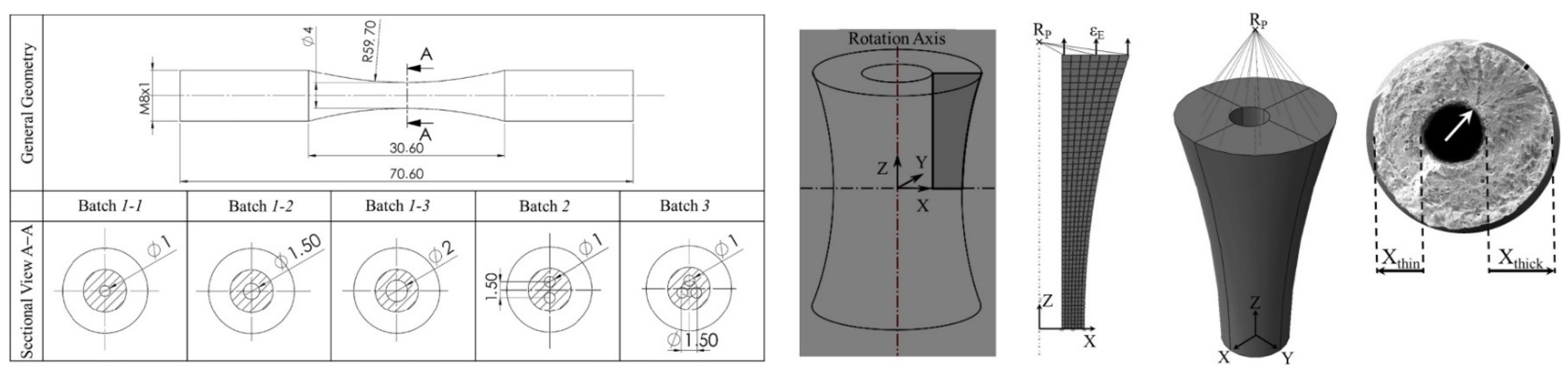
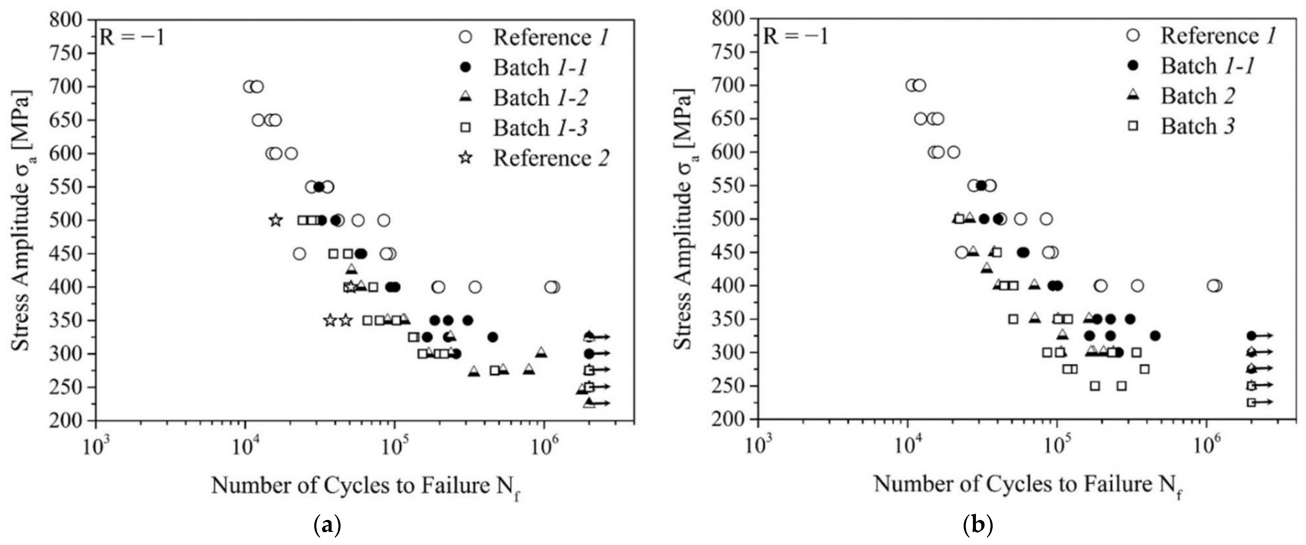
| Günther et al. [118] | L-PBF | Figure 8 | Resonant testing machine with symmetrical push-pull loading at R = −1 and 105 Hz | Figure 9 |
Razavi et al. [108] developed non-porous and induced microporous samples with internal voids and defects across each layer of parts using LENS technology. When comparing non-porous and porous specimens under uniaxial tensile loading fatigue test with a stress ratio of R = 0.01 (stress or load ratio (R) is the ratio between the minimum compressive fatigue stress (σmin) and the maximum fatigue stress (σmax)), porous samples showed 75% reduction in stress range at one million cycles. This implies porosity to be the main contributor to a significant reduction in fatigue life. Studies by Li et al. [102,119] used vacuum diffusion bonding of alloy meshed to develop a non-gradient porous Ti64 structure with a designed porosity of 50%, 60%, and 70% and found the normalized fatigue strength at 106 cycles to be in the range of 0.50–0.60 under compression-compression fatigue test at a load ratio of 0.1. The normalized fatigue strength was higher than the normalized fatigue strength of other porous Ti64 alloys developed using powder sintering and L-PBF.
Furthermore, the fabrication and post-processing conditions also highly influence the Ti64 porous implant material, its mechanical properties, and even its microstructure. In L-PBF, inherent heating and cooling speeds induce directionally dependent grain growth, internal porosity, and anisotropic microstructure [63]. Typically, additional post-processing heat treatment such as stress-relieving or hot isostatic pressing (HIP) are utilized to reduce internal porosity, to control the microstructure such that it improves mechanical properties, particularly ductility [63]. With HIP treatment, Wu et al. [114] reported that the strut porosity of L-PBF specimens were reduced to less than 0.001 vol.%. Regarding the microstructure, the α’- martensite phase, which is a common phase on the L-PBF specimens, can be transformed into the tougher α + β mixture phases by using the HIP process [106,114]. This phase transformation helps in resisting the propagation of fatigue cracks by crack blunting and thereby improving fatigue performance [106,114,120]. Furthermore, the fatigue life of porous Ti64 structures can also be improved using a sandblasting process as it induces compressive stress on the strut’s surface and removes partially melted particles [121].
In many load-bearing applications, compression is the primary loading mechanism, however, implants can sometimes experience tensile loads due to the stochastic nature of forces on the human body [63]. Pure compression loading does not usually result in fatigue failure in most continuous materials as compressive loads may suppress crack growth and prevent fatigue failure from happening [49]. When compressive fatigue loads are applied to porous structures at a macro-scale, tensile stress may be developed in the individual struts. Depending on the porous design, some unit cells can result in much more tensile stress than others [49]. However, a few literature studies focused on fatigue behavior at tensile loading are available. The detailed fatigue behavior of porous Ti64 implants under different testing conditions is presented in Table 4.
Figure 8.
The geometry of fatigue samples from the study by Günther et al. machined from raw cylinders and definition of different batches with all dimensions in mm. Reprinted with permission from ref. [118]. 2018, Elsevier Ltd.
Figure 8.
The geometry of fatigue samples from the study by Günther et al. machined from raw cylinders and definition of different batches with all dimensions in mm. Reprinted with permission from ref. [118]. 2018, Elsevier Ltd.

Figure 9.
(a) S-N curves of batches with different internal channels as shown in Figure 8, partly recompiled from their previous studies [122]. (b) S-N curves with different batches compared to the results by Leuders et al. [123] and Kasperovich et al. [124] designated as References [1,2], respectively. Reprinted with permission from ref. [118]. 2018, Elsevier Ltd.

5. Multifunctional Implant Design and Development
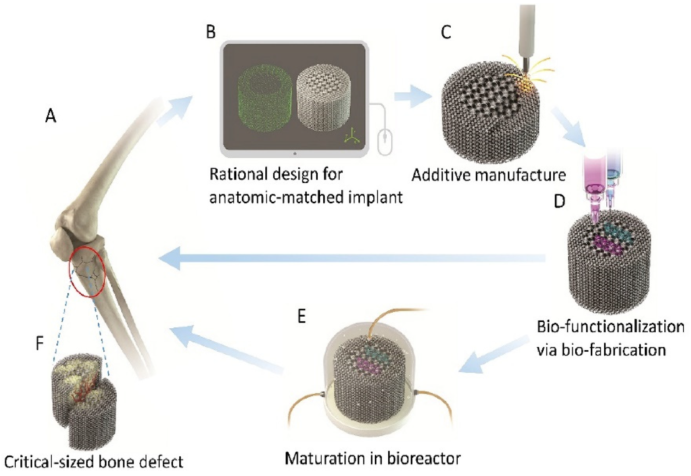
Innovative multifunctional porous implant design and development can be a possible approach towards better implant life and a reduced number of revision surgeries. As indicated in Figure 10, with additive manufacturing and tissue engineering, porous titanium implants can be custom fabricated to match patients’ anatomical structure with desirable porous geometry and multifunctionality for osseointegration. Poor implant integration with native bone at the implant interface is one of the major causes of implant failure [99]. Table 5 shows that depending on the objectives of studies, multifunctional porous implants have been developed for the improvement of mechanical properties, bonding on the bone-implant interface, bone volume fraction, bioactivity, osteointegration, antibacterial implant design, etc.
Ti-alloys have poor tribological behavior owing to their high friction coefficient and can cause significant adhesive wear generating debris resulting in inflammation and bone resorption [53]. In addition, the performance of ‘as-built’ Ti-alloy implants by AM processes are limited due to their low surface quality, surface imperfections, and defects introduced due to layer-by-layer deposition processes [53]. To resolve such issues, surface treatment can be used to enhance the resistance to tribology or corrosion of the as-fabricated AM parts [53]. Surface treatment alters surface roughness and modifies implant topography to improve biological response before implantation [38,125]. Studies show that surface treatment can be performed by sandblasting (S), electropolishing, acid-etching (E), anodization oxidation (AO), anode spark oxidation (ASO), heat treatment, and laser treatment (laser polishing, laser shock peening, laser remelting) [38,53,125]. Surface modification technique adds material of various thicknesses superficially on the implant surface to reduce roughness, mask cracks, improve surface strength, and improve tribological and/or corrosion resistance. Surface modification can be conducted by adding silver nanoparticles (AgNPs), silver nitrate (AgNO3), antibiotic mesoporous bioactive glass (MBG), calcium carbonate (CaCO3), and hydroxyapatite [38,53,125].
Multifunctional porous implant designs are mostly found to be subjected to surface modification treatments for property enhancement. The majority of the surface modification studies focus on coating Hydroxyapatite (HA) or other calcium phosphate compounds such as Tri-calcium phosphate (TCP) for improving bioactivity, biocompatibility, and cellular activities, such as cell adhesion, proliferation, differentiation, osteointegration, etc. [38,53]. Chudinova et al. [126] performed electrophoretic deposition of near-spherical calcium phosphate nanoparticles (CaPNPs) on the surface of AM Ti64 scaffolds and found homogeneous deposition of CaPNPs on Ti64 scaffolds surface with an improvement of both cell adhesion and growth. Besides HA surface modification, Jia et al. [127] developed a novel porous Ti64 implant with antibacterial properties via Electron Beam Melting combined with micro-arc oxidation (MAO). The release of silver nanoparticles (AgNPs) after implantation within the body acts as an antibacterial agent, which prevents biofilm formation at the bone-implant interface, thus enhancing the implant success rate. Another study by Fazel et al. [39] developed a multifunctional layer on Ti64 implants, a hierarchically structured surface including an interconnected microporous TiO2 layer containing silver nanoparticles and hydroxyapatite nanocrystals through plasma electrolytic oxidation (PEO) followed by hydrothermal treatment (HT), where they found that HT and spindle-like HA nanocrystals showed sustained antibacterial activity, a higher level of pre-osteoblasts metabolic activity, and a higher level of alkaline phosphate activity as compared to PEO-treated implants without HT. Hengel et al. [128] designed a novel functionality-packed implant using a surface biofunctionalization technique to prevent aseptic loosening through stimulation of the osteogenic differentiation of stem cells, as well as septic loosening through the short-and long-term delivery of antibacterial agents from the entire volume of porous structure (detailed multifunctionality design listed in Table 5). The multiple active agents were incorporated into the micro- and nano-topographical structure uniformly throughout the entire surface. In addition to the surface modification, Li et al. [129] mixed Ti64 powder with β- TCP to create interconnected porous structures and evaluated implants’ in vivo tissue reaction and osteoinductive potential. Detailed information on the functionalization of additively manufactured Ti alloys for orthopedic implants can be found in the review paper by Jing et al. [27].
The use of Mg alloys in implants helps in reducing the relative elastic modulus, makes implant bioresorbable, and more importantly, helps in creating bioactive systems [15,130]. Perets et al. [130] designed biodegradable Titanium-Magnesium (Ti-Mg) non-gradient porous implants. Even though the utilization of bioresorbable material with Ti64 has high potential in future implant materials, detailed studies on the in vivo corrosion rate of these novel porous implants are required, otherwise, the multifunctional porous implants may end up losing their mechanical integrity before bone healing, demanding for revision surgery. Furthermore, the potential of the NiTi–Ti64 multi-material cellular structured hip implant has been studied by Bartolomeu et al. [131] with a broader objective of creating implants with customized stiffness, superior wear resistance, and a controlled NiTi outer region volume change. Multifunctional porous implant studies are mostly found to be focused on evaluating the performance (mechanical and biological) of as-prepared porous implants.
Table 5.
Multifunctional Porous Implants.
| Author | Process | Multifunctionality Design | Test Subject | Study Duration | Key Findings |
|---|---|---|---|---|---|
| Rahmani et al. [68] | L-PBF | 99.9% purity wollastonite (CaSiO3) with a particle size of 1–5 µm filled and sintered (frittage) inside an argon-atomized Ti64 cellular lattice structure via an SPS machine; Five different TPMS scaffold structures | N/A | N/A | L-PBF-manufactured Ti64 lattice can be sintered via SPS along with CaSiO3 for load-bearing bone replacements; Rectangular and honeycomb were identified to be novel cellular scaffolds for high compressive load-bearing and biological application respectively; Rectangular scaffold suitable for oxygen transport and fluid permeability, whereas honeycomb is best for the growth of cells. |
| Goto et al. [83] | EBM | ACaHW treatment (NaOH, CaCl2, heat, and water) | Rabbits | 4, 8, and 12 weeks | Treated implants showed direct bonding of bone to the metal surface without the interposition of fibrous tissue (higher affinity to the bone than the untreated one) |
| Jia et al. [127] | EBM-MAO | Silver nanoparticles (AgNPs) deposition onto the micro-roughened surface | In-vitro | 5 days | Micro-nanoporous MAO layer stimulated cell adhesion and considerably increased the cell number and improved cell morphology while subsequent nano-silver immobilization, inspired by the mussel’s adhesive versatility, yielded potential antibacterial surfaces |
| Hengel et al. [128] | L-PBF (Ti64-ELI) | Miniaturized implant geometry optimized for murine femora implantation; Hexagonal unit cell, Total Length 4 cm and diameter 0.5 mm. A surface-to-volume ratio of 35.6 Biofunctionalized using plasma electrolytic oxidation to locally release both osteogenic (i.e., strontium) and anti-bacterial (i.e., silver ions) agents, along with the incorporation of hydroxyapatite into the surface of the implant in a same single-step | In vitro and Ex vivo (mouse) | In-vitro: 1, 3, 7 and 11 days Ex-vivo: 24 h | Tremendous potential use of synergistic antibacterial behavior between silver ions and strontium allowing for simultaneously reduced required dose of silver ions by 4–32 folds while inducing osteogenic behavior |
| Li et al. [129] | 3DF 1 | Ti64-β-TCP hybrid scaffold with interconnected porous network | Dogs | 12 weeks | Hierarchical porous structure and mechanical properties between cancellous and cortical bone. Enhanced bioactivity of hybrid scaffolds with 10 wt.% TCP ceramic as compared to the scaffold without and with a lower concentration of TCP |
| Perets et al. [130] | L-PBF | Permanent matrix of Ti lattice infiltrated with biodegradable Mg-based alloy (Mg-2.4%Nd-0.6%Y-0.3%Zr) | In-vitro | 24 h and 48 h | Stable stress–strain curve and higher Ultimate Compressive Strength and Yield point compared to Ti- lattice; positive cell viability response compliant to the ISO-10990-5 requirements |
| Bartolomeu et al. [131] | L-PBF | Dense Ti64 and/or Ti64 cellular structure fabricated on top of NiTi cellular structure to create multi-material implant design | N/A | N/A | Effective mechanical interlocking (shear strength of ≈33.2 MPa) between NiTi and Ti64 material in the transition region; the austenite phase on the NiTi region indicated the need for further investigations regarding thermal treatments for the martensite shape-memory phase |
| Lei et al. [132] | L-PBF | Surface bio-activation by alkaline-heat treatment (5 mol L−1 NaOH, 98% wt. for 1 h at 60 °C) | In-vitro | 1, 3, and 7 days | The overall distribution of cells on regular porous scaffolds was similar to the orderly arrangement of cultivated crops in the field, and the microporous structure of scaffolds with an aperture close to cell size was more suitable for cell proliferation and adhesion |
| Kayacan et al. [133] | L-PBF | Transitive porous implants of semispherical and elliptical pores of 500 µm at outer region and cell development channels of 200 µm at the inner region | Sheep | 12 weeks | Semispherical porous structure resulted in the formation of a strong and durable bond between tissues and implant Due to the transitive porous structure, a strong and durable tissue bond could be formed at the bone–implant interface |
| Zhang et al. (2018) [134] | L-PBF | Porous scaffolds with 5 strut sizes—0.2, 0.25, 0.3, 0.35, and 0.4 µm Hydroxyapatite layer coated at the surface to promote osteoconductivity | Beagle Dogs | 1, 4, and 6 months | No infection of the surgical sites, implants dislocation, or adverse reactions, such as inflammation or foreign body reaction around the implantation sites; Beagles limp on their right legs in the first two weeks, but they can walk freely after one-month implantation. After four months, the implants had little effect on their movement. After six months, new bone tissues gradually grow into porous implants. The damaged legs were completely repaired, and it was hard to detect the initial injury from the beagle’s gait walking. |
| Li et al. (2019) [135] | L-PBF (Ti64 ELI) | Alkali–acid-heat (AH) treatment on the porous Ti64 scaffold (AH-porous Ti64) followed by hydrothermal treatment to enable HA coating with nanopillar-like morphology (HT/AH-porous Ti64) | In-vitro | ALP activity: 7, 14, and 21 days | HT/AH-porous Ti64 exhibited the highest apatite formation ability and best affinity to fibronectin and vitronectin; In vitro studies indicated improved adhesion and differentiation on the HT/AH-porous Ti64 as compared with the porous Ti64 and AH-porous Ti64 |
| San Cheong et al. [136] | L-PBF | Hydroxyapatite (HA) Coating on the porous scaffolds with pore sizes of 700 and 1500 µm; FEA and in vivo analysis | Sheep | 6 weeks | Novel Finite Element algorithms to simulate bone ingrowth to improve implant design; FEA models results showed that reduction in implant stiffness increases bone ingrowth; Osteoconductive HA coating improved osteointegration—bone volume increases by >10%. |
| Bandyopadhyaya et al. [137] | LENSTM (Ta and Ti64) | 30 vol.% porous Ti64 (30Ti64) 30 vol.% porous Ti64 with titania (TiO2) nanotube modified surface (30TNT) 30 vol.% with porous Ta (30Ta) | Rat | 5 and 12 weeks | 30TNT showed comparable osteoid formation to 30Ta around the implant, which is significantly higher than 30Ti64 controls at 5 weeks; 30Ta outperform 30TNT and 30Ti64 at 12 weeks |
| MacBarb et al. [138] | EBM (Ti64 ELI) | AM discs with a 1.25 mm thick- solid base and a 0.75 mm thick- porous surface layer; Layer of nanocrystalline HA (~20 nm thick) coated to the disc surface using a dip, spin, and heat treatment technique; Target Pore size—300 μm and porosity 60–70% porosity; Measured mean Pore size 290.6 µm and mean porosity of 60.0% | In-vitro | 2, 7, 14, and 21 days | Cells on AM discs exhibited expedited proliferative activity when compared to titanium plasma spray (TPS) coated samples; 48% higher calcium production on AM discs than on TPS discs; No significant enhancement of cellular activities with HA-coating; Additive manufactured porous titanium surfaces can be alternative to TPS-coating for orthopedic spinal implants |
1 Three-dimensional fiber deposition (3-DF).
6. Current Challenges and Literature Gaps
New bone formation is normally facilitated by spaces in pores for bone growth and larger porosity of over 75% as they improve the bodily fluid permeability [99]. The higher the porosity of implants, the weaker the mechanical strength it would be. A higher degree of control over the macro-level-porosity pore sizes and strut thickness can be achieved through lattice/unit cell designs, however, control over the microlevel porous design can be challenging, especially for processes such as L-PBF. The use of additive manufacturing for the fabrication of medical devices has two major advantages of ‘batch-size-indifference’ and ‘complexity-for-free’ [48]. Batch-size-indifference provides the feasibility of producing patient-specific biomaterials, implants, and surgical instruments that exactly match the complex and highly variable anatomy of individual patients. Whereas, complexity-for-free provides freedom to designers to use complex geometries that give rise to favorable properties and advanced functionalities [48]. Implants made of Ti64 alloy are biocompatible in nature, however, the bioactivity of Ti64 implants can be enhanced both in vitro and in vivo by surface coating them with bone-like apatite for better bone ingrowth performance and success rate of the implants [139]. Orthopedic implants can be patient-specific and the need for additional surface coating/surface activation adds to the manufacturing costs of the implants [41,53].
In addition to the mechanical properties and porous structure, permeability, fatigue behavior, surface area and many other properties of additively manufactured porous implant structures can be adjusted through the application of geometrical designs [39]. Even with the optimum geometrical design, it is difficult to address all the challenges associated with the orthopedic implants and there exists a tradeoff between porosity and stiffness/strength while simultaneously promoting osseointegration and avoiding pore occlusion [39,64,103]. Muthaiah et al. [53] suggested that a new functionally graded porosity implant with bioceramic coating should be developed to mimic natural bone and provide a good interfacial bond between bone tissue and metallic implants. Currently, the primary challenges in the clinical use of AM porous implant structures are in guaranteeing the consistency of material produced and its optimum performance [43].
It is especially challenging to evaluate periprosthetic bone loss prior to an operation based on the X-rays and computed tomography (CT) and makes it difficult to design the implant accurately [92]. Furthermore, the proneness of porous implants towards fatigue failure as compared to their solid counterparts can be a challenging factor that requires careful consideration, but limited studies have been conducted on the fatigue behavior of porous structures. In addition, the orthopedic implants are often subjected to cyclic tensile load as discussed in Section 4.3, which demands more studies on fatigue tensile behavior of these porous structures.
Many researchers lack the resources and manpower for in vivo testing, although these in vivo studies form an essential part of novel implant performance studies. Furthermore, the in vivo studies are performed for a limited time duration. Extensive and rigorous animal studies for longer durations is required for novel and innovative multifunctional porous implant designs, as the porous implants’ strength/performance may deteriorate differently than what was observed in shorter duration studies, such as for Ti64 implant infiltrated with biodegradable material. Despite the closeness of gradient designs to bone morphology, compared to non-gradient designs, most of the articles in the literature were found to be focused on non-gradient Ti64 structures. More comprehensive studies on gradient porosity design are required so that the findings of varying research approaches in AM implant development converge into addressing current challenges, such as insufficient bone, vascularization, contiguous infection, and implant longevity [54]. Furthermore, as most of the additive manufacturing processes demand post-processing, studies on the effect of post-processing treatments on internal porosity, surface roughness, mechanical properties, fatigue behaviors, and biocompatibility properties can be of particular interest.
The application of conventional surface finishing techniques to AM porous implants is insignificant mainly due to porous structures, partial adhesion of powder feedstock and variable roughness with the orientation of the AM implants and possible needs for variable finishes across implants, and therefore demands the need of new advanced surface finishing techniques [43]. Although there has been huge progress in the field of surface engineering on AM manufactured Ti-implants, there is still significant scope for continued research such that a thorough understanding of the process involved in each surface treatment, systematic experimental studies, advanced analytical solutions, and computational simulations can be achieved [53]. The regulating agencies around the world are quite aware of the importance of this issue, however, with the rapid development and technological advancement in AM of medical devices, these directions have not been necessarily kept up and still pose some unique challenges in meeting requirements and establishing regulatory standards associated with quality assurance in manufacturing [54]. More importantly, there is a need for re-scrutinizing the regulatory position on the breadth of the ‘design envelope’ covering mass-manufactured AM porous implants [43].
7. Conclusions
Additive manufacturing technology is gaining rapid interest in orthopedic implant design and development due to its design freedom, which allows for patient-specific custom implant designs. In this systemic review, besides the porous design, mechanical properties, in vitro and in vivo biological properties, fatigue behaviors and multifunctionality of AM porous Ti64 implants were carefully reviewed and presented thoroughly for all the AM processes currently utilized in the design and development of these porous Ti64 implants/scaffolds. This review article helps in mitigating the current gap in the existing review articles on AM porous Ti64 related to the review of different AM processes, fatigue behavior and critical design aspects of these porous implants. To reduce the stress-shielding effects of solid titanium implants, researchers are currently focusing on the design and development of porous Ti64 alloy implants along with the aim of creating novel multifunctional implants. Most of the porous Ti64 implants were fabricated using either a laser powder bed fusion or an electron beam melting process. Research studies on porous Ti64 implants suggest that they can be tailored to mimic the mechanical properties (Young’s modulus, mechanical strength, etc.) similar to natural bone. Different macroporous cellular structures can be utilized to improve the fluid permeability/cellular activity within the Ti64 bone implants. Furthermore, bioactive, and antibacterial surface modification, infusion of bioactive materials within the Ti64 matrix, and surface treatment to form functionally packed porous implants have a perspective towards future multifunctional orthopedic Ti64 alloy implants. Since gradient porous design mimics closest to the natural bone and has promising potential as orthopedic implants/scaffolds, more studies on these gradient designs are necessary. Further in-depth studies on design, mechanical, fatigue, biological, and multi-functionality aspects of porous Ti64 along with the convergence of future study findings, can turn the porous Ti64 implants into feasible alternatives for the currently expensive Tantalum implants. The comparison of AM porous Ti64 with other manufacturing techniques for orthopedic implant/scaffold can also be an interesting topic for future study, such that their respective advantages and disadvantages can be identified.
Author Contributions
Conceptualization, N.K. and S.N.; methodology, N.K. and S.N.; validation, N.K., S.N. and B.F.; formal analysis, N.K. and S.N.; investigation, N.K. and S.N.; resources, N.K. and S.N.; data curation, N.K. and S.N.; writing—original draft preparation, N.K. and S.N.; writing—review and editing, N.K., S.N. and B.F.; visualization, N.K. and S.N.; supervision, N.K. and S.N. All authors have read and agreed to the published version of the manuscript.
Funding
This research received no external funding.
Institutional Review Board Statement
Not applicable.
Informed Consent Statement
Not applicable.
Data Availability Statement
Data sharing is not applicable.
Acknowledgments
We thank Li Yang, Department of Industrial Engineering, J.B. Speed School of Engineering, University of Louisville, for his valuable feedback, comments, and continuous support on this review paper.
Conflicts of Interest
The authors declare no conflict of interest.
References
- Wauthle, R.; Ahmadi, S.M.; Yavari, S.A.; Mulier, M.; Zadpoor, A.A.; Weinans, H.; Van Humbeeck, J.; Kruth, J.-P.; Schrooten, J. Revival of pure titanium for dynamically loaded porous implants using additive manufacturing. Mater. Sci. Eng. C Mater. Biol. Appl. 2015, 54, 94–100. [Google Scholar] [CrossRef] [PubMed]
- Galante, J.; Rostoker, W.; Lueck, R.; Ray, R.D. Sintered fiber metal composites as a basis for attachment of implants to bone. JBJS 1971, 53, 101–114. [Google Scholar] [CrossRef]
- Levine, B. A New Era in Porous Metals: Applications in Orthopaedics. Adv. Eng. Mater. 2008, 10, 788–792. [Google Scholar] [CrossRef]
- Andani, M.T.; Moghaddam, N.S.; Haberland, C.; Dean, D.; Miller, M.J.; Elahinia, M. Metals for bone implants. Part 1. Powder metallurgy and implant rendering. Acta Biomater. 2014, 10, 4058–4070. [Google Scholar] [CrossRef]
- Exhibit 19. HCUP estimates of the total number of target procedures. Content last reviewed April 2018. Agency for Healthcare Research and Quality, Rockville, MD. Available online: https://www.ahrq.gov/research/findings/final-reports/ssi/ssiexh19.html (accessed on 16 November 2021).
- OSSDSIGN AB Annual Report 2020. OSSDSIGN AB. 8 June 2020. Available online: https://www.ossdsign.com/reports-engelska (accessed on 16 November 2021).
- Rezwan, K.; Chen, Q.Z.; Blaker, J.J.; Boccaccini, A.R. Biodegradable and bioactive porous polymer/inorganic composite scaffolds for bone tissue engineering. Biomaterials 2006, 27, 3413–3431. [Google Scholar] [CrossRef]
- Devin, J.E.; Attawia, M.A.; Laurencin, C.T. Three-dimensional degradable porous polymer-ceramic matrices for use in bone repair. J. Biomater. Sci. Polym. Ed. 1996, 7, 661–669. [Google Scholar] [CrossRef]
- Spector, M.; Michno, M.J.; Smarook, W.H.; Kwiatkowski, G.T. A high-modulus polymer for porous orthopedic implants: Biomechanical compatibility of porous implants. J. Biomed. Mater. Res. 1978, 12, 665–677. [Google Scholar] [CrossRef]
- Johnson, K.D.; Frierson, K.E.; Keller, T.S.; Cook, C.; Scheinberg, R.; Zerwekh, J.; Meyers, L.; Sciadini, M.F. Porous ceramics as bone graft substitutes in long bone defects: A biomechanical, histological, and radiographic analysis. J. Orthop. Res. 1996, 14, 351–369. [Google Scholar] [CrossRef]
- Sopyan, I.; Mel, M.; Ramesh, S.; Khalid, K.A. Porous hydroxyapatite for artificial bone applications. Sci. Technol. Adv. Mater. 2007, 8, 116–123. [Google Scholar] [CrossRef] [Green Version]
- Uchida, A.; Nade, S.M.; McCartney, E.R.; Ching, W. The use of ceramics for bone replacement. A comparative study of three different porous ceramics. J. Bone Jt. Surg. 1984, 66, 269–275. [Google Scholar] [CrossRef]
- Will, J.; Melcher, R.; Treul, C.; Travitzky, N.; Kneser, U.; Polykandriotis, E.; Horch, R.E.; Greil, P. Porous ceramic bone scaffolds for vascularized bone tissue regeneration. J. Mater. Sci. Mater. Med. 2008, 19, 2781–2790. [Google Scholar] [CrossRef] [PubMed]
- Chen, Z.; Yan, X.; Chang, Y.; Xie, S.; Ma, W.; Zhao, G.; Liao, H.; Fang, H.; Liu, M.; Cai, D. Effect of polarization voltage on the surface componentization and biocompatibility of micro-arc oxidation modified selective laser melted Ti6Al4V. Mater. Res. Express 2019, 6, 086425. [Google Scholar] [CrossRef]
- Li, Y.; Jahr, H.; Zhou, J.; Zadpoor, A.A. Additively manufactured biodegradable porous metals. Acta Biomater. 2020, 115, 29–50. [Google Scholar] [CrossRef]
- Yuan, L.; Ding, S.; Wen, C. Additive manufacturing technology for porous metal implant applications and triple minimal surface structures: A review. Bioact. Mater. 2019, 4, 56–70. [Google Scholar] [CrossRef] [PubMed]
- Wang, X.; Xu, S.; Zhou, S.; Xu, W.; Leary, M.; Choong, P.; Qian, M.; Brandt, M.; Xie, Y.M. Topological design and additive manufacturing of porous metals for bone scaffolds and orthopaedic implants: A review. Biomaterials 2016, 83, 127–141. [Google Scholar] [CrossRef] [PubMed]
- Revilla-León, M.; Sadeghpour, M.; Özcan, M. A Review of the Applications of Additive Manufacturing Technologies Used to Fabricate Metals in Implant Dentistry. J. Prosthodont. 2020, 29, 579–593. [Google Scholar] [CrossRef] [PubMed]
- Ryan, G.; Pandit, A.; Apatsidis, D.P. Fabrication methods of porous metals for use in orthopaedic applications. Biomaterials 2006, 27, 2651–2670. [Google Scholar] [CrossRef]
- Wang, Z.; Wang, C.; Li, C.; Qin, Y.; Zhong, L.; Chen, B.; Li, Z.; Liu, H.; Chang, F.; Wang, J. Analysis of factors influencing bone ingrowth into three-dimensional printed porous metal scaffolds: A review. J. Alloys Compd. 2017, 717, 271–285. [Google Scholar] [CrossRef]
- Zhao, W.; Huang, Z.; Liu, L.; Wang, W.; Leng, J.; Liu, Y. Porous bone tissue scaffold concept based on shape memory PLA/Fe3O4. Compos. Sci. Technol. 2021, 203, 108563. [Google Scholar] [CrossRef]
- Zerankeshi, M.M.; Bakhshi, R.; Alizadeh, R. Polymer/metal composite 3D porous bone tissue engineering scaffolds fabricated by additive manufacturing techniques: A review. Bioprinting 2022, 25, e00191. [Google Scholar] [CrossRef]
- Attar, H.; Ehtemam-Haghighi, S.; Soro, N.; Kent, D.; Dargusch, M.S. Additive manufacturing of low-cost porous titanium-based composites for biomedical applications: Advantages, challenges and opinion for future development. J. Alloys Compd. 2020, 827, 154263. [Google Scholar] [CrossRef]
- Bose, S.; Koski, C.; Vu, A.A. Additive manufacturing of natural biopolymers and composites for bone tissue engineering. Mater. Horiz. 2020, 7, 2011–2027. [Google Scholar] [CrossRef]
- Neumann, M.; Epple, M. Composites of Calcium Phosphate and Polymers as Bone Substitution Materials. Eur. J. Trauma 2006, 32, 125–131. [Google Scholar] [CrossRef]
- Ødegaard, K.S.; Torgersen, J.; Elverum, C.W. Structural and Biomedical Properties of Common Additively Manufactured Biomaterials: A Concise Review. Metals 2020, 10, 1677. [Google Scholar] [CrossRef]
- Jing, Z.; Zhang, T.; Xiu, P.; Cai, H.; Wei, Q.; Fan, D.; Lin, X.; Song, C.-L.; Liu, Z. Functionalization of 3D-printed titanium alloy orthopedic implants: A literature review. Biomed. Mater. 2020, 15, 052003. [Google Scholar] [CrossRef] [PubMed]
- Carter, L.N.; Addison, O.; Naji, N.; Seres, P.; Wilman, A.H.; Shepherd, D.E.; Grover, L.; Cox, S. Reducing MRI susceptibility artefacts in implants using additively manufactured porous Ti-6Al-4V structures. Acta Biomater. 2020, 107, 338–348. [Google Scholar] [CrossRef] [PubMed]
- Frydman, G.H.; Marini, R.P.; Bakthavatchalu, V.; Biddle, K.E.; Muthupalani, S.; Vanderburg, C.R.; Lai, B.; Bendapudi, P.K.; Tompkins, R.G.; Fox, J.G. Local and systemic changes associated with long-term, percutaneous, static implantation of titanium alloys in rhesus macaques (Macaca mulatta). Comp. Med. 2017, 67, 165–175. [Google Scholar]
- Guo, T.; Gulati, K.; Arora, H.; Han, P.; Fournier, B.; Ivanovski, S. Race to invade: Understanding soft tissue integration at the transmucosal region of titanium dental implants. Dent. Mater. 2021, 37, 816–831. [Google Scholar] [CrossRef]
- Drnovšek, N.; Rade, K.; Milačič, R.; Štrancar, J.; Novak, S. The properties of bioactive TiO2 coatings on Ti-based implants. Surf. Coat. Technol. 2012, 209, 177–183. [Google Scholar] [CrossRef]
- Kim, K.T.; Eo, M.Y.; Nguyen, T.T.H.; Kim, S.M. General review of titanium toxicity. Int. J. Implant. Dent. 2019, 5, 10. [Google Scholar] [CrossRef] [Green Version]
- Noumbissi, S.; Scarano, A.; Gupta, S. A Literature Review Study on Atomic Ions Dissolution of Titanium and Its Alloys in Implant Dentistry. Materials 2019, 12, 368. [Google Scholar] [CrossRef] [PubMed] [Green Version]
- Wennerberg, A.; Ide-Ektessabi, A.; Hatkamata, S.; Sawase, T.; Johansson, C.; Albrektsson, T.; Martinelli, A.; Sodervall, U.; Odelius, H. Titanium release from implants prepared with different surface roughness. Clin. Oral Implant. Res. 2004, 15, 505–512. [Google Scholar] [CrossRef] [PubMed]
- Ng, S.; Das, S.; Ting, Y.-P.; Wong, R.; Chanchareonsook, N. Benefits and Biosafety of Use of 3D-Printing Technology for Titanium Biomedical Implants: A Pilot Study in the Rabbit Model. Int. J. Mol. Sci. 2021, 22, 8480. [Google Scholar] [CrossRef] [PubMed]
- Přikrylová, J.; Procházková, J.; Podzimek, Š. Side effects of dental metal implants: Impact on human health (metal as a risk factor of implantologic treatment). BioMed Res. Int. 2019, 2019, 2519205. [Google Scholar] [CrossRef] [PubMed]
- Sidambe, A.T. Biocompatibility of Advanced Manufactured Titanium Implants-A Review. Materials 2014, 7, 8168–8188. [Google Scholar] [CrossRef] [PubMed] [Green Version]
- Aufa, A.N.; Hassan, M.Z.; Ismail, Z. Recent advances in Ti-6Al-4V additively manufactured by selective laser melting for biomedical implants: Prospect development. J. Alloys Compd. 2022, 896, 163072. [Google Scholar] [CrossRef]
- Fazel, M.; Salimijazi, H.R.; Shamanian, M.; Minneboo, M.; Modaresifar, K.; van Hengel, I.A.; Fratila-Apachitei, L.E.; Apachitei, I.; Zadpoor, A.A. Osteogenic and antibacterial surfaces on additively manufactured porous Ti-6Al-4V implants: Combining silver nanoparticles with hydrothermally synthesized HA nanocrystals. Mater Sci. Eng. C Mater. Biol. Appl. 2021, 120, 111745. [Google Scholar] [CrossRef]
- Spece, H.; Basgul, C.; Andrews, C.E.; MacDonald, D.W.; Taheri, M.L.; Kurtz, S.M. A systematic review of preclinical in vivo testing of 3D printed porous Ti6Al4V for orthopedic applications, part I: Animal models and bone ingrowth outcome measures. J. Biomed. Mater. Res. Part B Appl. Biomater. 2021, 109, 1436–1454. [Google Scholar] [CrossRef]
- Zhang, X.-Y.; Fang, G.; Zhou, J. Additively Manufactured Scaffolds for Bone Tissue Engineering and the Prediction of their Mechanical Behavior: A Review. Materials 2017, 10, 50. [Google Scholar] [CrossRef] [Green Version]
- Murr, L.E. Strategies for creating living, additively manufactured, open-cellular metal and alloy implants by promoting osseointegration, osteoinduction and vascularization: An overview. J. Mater. Sci. Technol. 2019, 35, 231–241. [Google Scholar] [CrossRef]
- Lowther, M.; Louth, S.; Davey, A.; Hussain, A.; Ginestra, P.; Carter, L.; Eisenstein, N.; Grover, L.; Cox, S. Clinical, industrial, and research perspectives on powder bed fusion additively manufactured metal implants. Addit. Manuf. 2019, 28, 565–584. [Google Scholar] [CrossRef] [Green Version]
- Ahmadi, S.; Hedayati, R.; Jain, R.A.K.; Li, Y.; Leeflang, S.; Zadpoor, A. Effects of laser processing parameters on the mechanical properties, topology, and microstructure of additively manufactured porous metallic biomaterials: A vector-based approach. Mater. Des. 2017, 134, 234–243. [Google Scholar] [CrossRef]
- Raghavendra, S.; Molinari, A.; Fontanari, V.; Luchin, V.; Zappini, G.; Benedetti, M.; Johansson, F.; Klarin, J. Tensile and compression properties of variously arranged porous Ti-6Al-4V additively manufactured structures via SLM. Procedia Struct. Integr. 2018, 13, 149–154. [Google Scholar] [CrossRef]
- Hanks, B.; Berthel, J.; Frecker, M.; Simpson, T.W. Mechanical properties of additively manufactured metal lattice structures: Data review and design interface. Addit. Manuf. 2020, 35, 101301. [Google Scholar] [CrossRef]
- Loginov, Y.N.; Koptyug, A.; Popov, V.V.; Belikov, S.V.; Mukanov, G.; Golodnov, A.I.; Stepanov, S.I. Compression deformation and fracture behavior of additively manufactured Ti–6Al–4V cellular structures. Int. J. Lightweight Mater. Manuf. 2022, 5, 126–135. [Google Scholar] [CrossRef]
- Zadpoor, A.A. Additively manufactured porous metallic biomaterials. J. Mater. Chem. B 2019, 7, 4088–4117. [Google Scholar] [CrossRef] [PubMed] [Green Version]
- Zadpoor, A.A. Mechanics of additively manufactured biomaterials. J. Mech. Behav. Biomed. Mater. 2017, 70, 1–6. [Google Scholar] [CrossRef] [PubMed]
- Hedayati, R.; Ahmadi, S.; Lietaert, K.; Pouran, B.; Li, Y.; Weinans, H.; Rans, C.; Zadpoor, A.A. Isolated and modulated effects of topology and material type on the mechanical properties of additively manufactured porous biomaterials. J. Mech. Behav. Biomed. Mater. 2018, 79, 254–263. [Google Scholar] [CrossRef]
- Sarker, A.; Leary, M.; Fox, K. Metallic additive manufacturing for bone-interfacing implants. Biointerphases 2020, 15, 050801. [Google Scholar] [CrossRef]
- Attarilar, S.; Ebrahimi, M.; Djavanroodi, F.; Fu, Y.; Wang, L.; Yang, J. 3D Printing Technologies in Metallic Implants: A Thematic Review on the Techniques and Procedures. Int. J. Bioprinting 2021, 7, 21–46. [Google Scholar] [CrossRef]
- Muthaiah, V.S.; Indrakumar, S.; Suwas, S.; Chatterjee, K. Surface engineering of additively manufactured titanium alloys for enhanced clinical performance of biomedical implants: A review of recent developments. Bioprinting 2022, 25, e00180. [Google Scholar] [CrossRef]
- Li, J.; Cui, X.; Hooper, G.J.; Lim, K.S.; Woodfield, T.B.F. Rational design, bio-functionalization and biological performance of hybrid additive manufactured titanium implants for orthopaedic applications: A review. J. Mech. Behav. Biomed. Mater. 2020, 105, 103671. [Google Scholar] [CrossRef] [PubMed]
- Wegst, U.G.; Bai, H.; Saiz, E.; Tomsia, A.P.; Ritchie, R.O. Bioinspired structural materials. Nat. Mater. 2015, 14, 23–36. [Google Scholar] [CrossRef] [PubMed]
- Yadroitsava, I.; du Plessis, A.; Yadroitsev, I. Bone Regeneration on Implants of Titanium Alloys Produced by Laser Powder Bed Fusion: A Review, in Titanium for Consumer Applications; Froes, F., Qian, M., Niinom, M.I., Eds.; Elsevier: Amsterdam, The Netherlands, 2019; pp. 197–233. [Google Scholar]
- Lin, C.-Y.; Kang, J.-H. Mechanical Properties of Compact Bone Defined by the Stress-Strain Curve Measured Using Uniaxial Tensile Test: A Concise Review and Practical Guide. Materials 2021, 14, 4224. [Google Scholar] [CrossRef]
- Currey, J. The Structure and Mechanical Properties of Bone, in Bioceramics and Their Clinical Applications; Kokubo, T., Ed.; Woodhead Publishing: Solston, UK, 2008; pp. 3–27. [Google Scholar]
- Kim, T.; See, C.W.; Li, X.; Zhu, D. Orthopedic implants and devices for bone fractures and defects: Past, present and perspective. Eng. Regen. 2020, 1, 6–18. [Google Scholar] [CrossRef]
- Bone Healing. Available online: https://www.foothealthfacts.org/conditions/bone-healing (accessed on 17 November 2021).
- Bone Healing after Implantation. Available online: http://dentalis-implants.com/resources/bone-maintenance/bone-healing-after-implantation/ (accessed on 25 November 2021).
- Niinomi, M.; Nakai, M. Titanium-Based Biomaterials for Preventing Stress Shielding between Implant Devices and Bone. Int. J. Biomater. 2011, 2011, 836587. [Google Scholar] [CrossRef] [PubMed] [Green Version]
- Kelly, C.N.; Evans, N.T.; Irvin, C.W.; Chapman, S.C.; Gall, K.; Safranski, D.L. The effect of surface topography and porosity on the tensile fatigue of 3D printed Ti-6Al-4V fabricated by selective laser melting. Mater. Sci. Eng. C Mater. Biol. Appl. 2019, 98, 726–736. [Google Scholar] [CrossRef]
- Kelly, C.N.; Wang, T.; Crowley, J.; Wills, D.; Pelletier, M.H.; Westrick, E.R.; Adams, S.B.; Gall, K.; Walsh, W.R. High-strength, porous additively manufactured implants with optimized mechanical osseointegration. Biomaterials 2021, 279, 121206. [Google Scholar] [CrossRef]
- Li, G.; Wang, L.; Pan, W.; Yang, F.; Jiang, W.; Wu, X.; Kong, X.; Dai, K.; Hao, Y. In vitro and in vivo study of additive manufactured porous Ti6Al4V scaffolds for repairing bone defects. Sci. Rep. 2016, 6, 1–11. [Google Scholar] [CrossRef] [Green Version]
- Titanium Alloy Guide; RMI Titanium Company: Niles, OH, USA, 2000; pp. 1–48.
- Ahmadi, S.M.; Jain, R.K.A.K.; Zadpoor, A.A.; Ayas, C.; Popovich, V.A. Effects of heat treatment on microstructure and mechanical behaviour of additive manufactured porous Ti6Al4V. Int. Conf. Smart Mater. Res. 2018, 293, 012009. [Google Scholar] [CrossRef]
- Rahmani, R.; Antonov, M.; Kollo, L.; Holovenko, Y.; Prashanth, K.G. Mechanical Behavior of Ti6Al4V Scaffolds Filled with CaSiO3 for Implant Applications. Appl. Sci. 2019, 9, 3844. [Google Scholar] [CrossRef] [Green Version]
- Xiong, Y.; Wang, W.; Gao, R.; Zhang, H.; Dong, L.; Qin, J.; Wang, B.; Jia, W.; Li, X. Fatigue behavior and osseointegration of porous Ti-6Al-4V scaffolds with dense core for dental application. Mater. Des. 2020, 195, 108994. [Google Scholar] [CrossRef]
- Koch, K.; Hargreaves, B.; Pauly, K.B.; Chen, W.; Gold, G.; King, K. Magnetic resonance imaging near metal implants. J. Magn. Reson. Imaging 2010, 32, 773–787. [Google Scholar] [CrossRef] [PubMed]
- Melancon, D.; Bagheri, Z.; Johnston, R.; Liu, L.; Tanzer, M.; Pasini, D. Mechanical characterization of structurally porous biomaterials built via additive manufacturing: Experiments, predictive models, and design maps for load-bearing bone replacement implants. Acta Biomater. 2017, 63, 350–368. [Google Scholar] [CrossRef]
- Yadroitsev, I.; Krakhmalev, P.; Yadroitsava, I. Hierarchical design principles of selective laser melting for high quality metallic objects. Addit. Manuf. 2015, 7, 45–56. [Google Scholar] [CrossRef]
- Gibson, I.; Rosen, D.; Stucker, B. Powder Bed Fusion Processes, in Additive Manufacturing Technologies: 3D Printing, Rapid Prototyping, and Direct Digital Manufacturing; Gibson, I., Rosen, D., Stucker, B., Eds.; Springer: New York, NY, USA, 2015; pp. 107–145. [Google Scholar]
- Weißmann, V.; Drescher, P.; Seitz, H.; Hansmann, H.; Bader, R.; Seyfarth, A.; Klinder, A.; Jonitz-Heincke, A. Effects of Build Orientation on Surface Morphology and Bone Cell Activity of Additively Manufactured Ti6Al4V Specimens. Materials 2018, 1, 915. [Google Scholar] [CrossRef] [Green Version]
- Sarker, A.; Tran, N.; Rifai, A.; Brandt, M.; Tran, P.; Leary, M.; Fox, K.; Williams, R. Rational design of additively manufactured Ti6Al4V implants to control Staphylococcus aureus biofilm formation. Materialia 2019, 5, 100250. [Google Scholar] [CrossRef]
- Huber, F.; Papke, T.; Scheitler, C.; Hanrieder, L.; Merklein, M.; Schmidt, M. In Situ Formation of a Metastable β-Ti Alloy by Laser Powder Bed Fusion (L-PBF) of Vanadium and Iron Modified Ti-6Al-4V. Metals 2018, 8, 1067. [Google Scholar] [CrossRef] [Green Version]
- Ødegaard, K.S.; Ouyang, L.; Ma, Q.; Buene, G.; Wan, D.; Elverum, C.W.; Torgersen, J.; Standal, T.; Westhrin, M. Revealing the influence of electron beam melted Ti-6Al-4V scaffolds on osteogenesis of human bone marrow-derived mesenchymal stromal cells. J. Mater Sci. Mater Med. 2021, 32, 97. [Google Scholar] [CrossRef]
- Chen, C.; Hao, Y.; Bai, X.; Ni, J.; Chung, S.-M.; Liu, F.; Lee, I.-S. 3D printed porous Ti6Al4V cage: Effects of additive angle on surface properties and biocompatibility; bone ingrowth in Beagle tibia model. Mater. Des. 2019, 175, 107824. [Google Scholar] [CrossRef]
- Hudák, R.; Schnitzer, M.; Králová, Z.; Gorejová, R.; Mitrík, L.; Rajťúková, V.; Tóth, T.; Kovačević, M.; Riznič, M.; Oriňaková, R.; et al. Additive Manufacturing of Porous Ti6Al4V Alloy: Geometry Analysis and Mechanical Properties Testing. Appl. Sci. 2021, 11, 2611. [Google Scholar] [CrossRef]
- Wieding, J.; Jonitz, A.; Bader, R. The Effect of Structural Design on Mechanical Properties and Cellular Response of Additive Manufactured Titanium Scaffolds. Materials 2012, 5, 1336–1347. [Google Scholar] [CrossRef]
- Wieding, J.; Fritsche, A.; Heinl, P.; Körner, C.; Cornelsen, M.; Seitz, H.; Mittelmeier, W.; Bader, R. Biomechanical behavior of bone scaffolds made of additive manufactured tricalciumphosphate and titanium alloy under different loading conditions. J. Appl. Biomater. Funct Mater 2013, 11, e159–e166. [Google Scholar] [CrossRef] [PubMed]
- El-Sayed, M.A.; Essa, K.; Ghazy, M.; Hassanin, H. Design optimization of additively manufactured titanium lattice structures for biomedical implants. Int. J. Adv. Manuf. Technol. 2020, 110, 2257–2268. [Google Scholar] [CrossRef]
- Goto, M.; Matsumine, A.; Yamaguchi, S.; Takahashi, H.; Akeda, K.; Nakamura, T.; Asanuma, K.; Matsushita, T.; Kokubo, T.; Sudo, A. Osteoconductivity of bioactive Ti-6Al-4V implants with lattice-shaped interconnected large pores fabricated by electron beam melting. J. Biomater. Appl. 2021, 35, 1153–1167. [Google Scholar] [CrossRef]
- Balcı, A.; Küçükaltun, F.; Aycan, M.F.; Usta, Y.; Demir, T. Reproducibility of Replicated Trabecular Bone Structures from Ti6Al4V Extralow Interstitials Powder by Selective Laser Melting. Arab. J. Sci. Eng. 2021, 46, 2527–2541. [Google Scholar] [CrossRef]
- Chen, Y.; Frith, J.; Dehghan-Manshadi, A.; Attar, H.; Kent, D.; Soro, N.D.M.; Bermingham, M.; Dargusch, M.S. Mechanical properties and biocompatibility of porous titanium scaffolds for bone tissue engineering. J. Mech. Behav. Biomed. Mater. 2017, 75, 169–174. [Google Scholar] [CrossRef]
- Tsai, P.-I.; Lam, T.-N.; Wu, M.-H.; Tseng, K.-Y.; Chang, Y.-W.; Sun, J.-S.; Li, Y.-Y.; Lee, M.-H.; Chen, S.-Y.; Chang, C.-K.; et al. Multi-scale mapping for collagen-regulated mineralization in bone remodeling of additive manufacturing porous implants. Mater. Chem. Phys. 2019, 230, 83–92. [Google Scholar] [CrossRef]
- Mitsak, A.G.; Kemppainen, J.M.; Harris, M.T.; Hollister, S.J. Effect of Polycaprolactone Scaffold Permeability on Bone Regeneration In Vivo. Tissue Eng. Part A 2011, 17, 1831–1839. [Google Scholar] [CrossRef] [Green Version]
- Arjunan, A.; Demetriou, M.; Baroutaji, A.; Wang, C.J. Mechanical performance of highly permeable laser melted Ti6Al4V bone scaffolds. J. Mech. Behav. Biomed. Mater. 2020, 102, 103517. [Google Scholar] [CrossRef]
- Hameed, P.; Liu, C.-F.; Ummethala, R.; Singh, N.; Huang, H.-H.; Manivasagam, G.; Prashanth, K.G. Biomorphic porous Ti6Al4V gyroid scaffolds for bone implant applications fabricated by selective laser melting. Prog. Addit. Manuf. 2021, 6, 455–469. [Google Scholar] [CrossRef]
- Zhang, S.; Wei, Q.; Cheng, L.; Li, S.; Shi, Y. Effects of scan line spacing on pore characteristics and mechanical properties of porous Ti6Al4V implants fabricated by selective laser melting. Mater. Des. 2014, 63, 185–193. [Google Scholar] [CrossRef]
- Coffigniez, M.; Gremillard, L.; Balvay, S.; Lachambre, J.; Adrien, J.; Boulnat, X. Direct-ink writing of strong and biocompatible titanium scaffolds with bimodal interconnected porosity. Addit. Manuf. 2021, 39, 101859. [Google Scholar] [CrossRef]
- Kan, T.; Xie, K.; Qu, Y.; Ai, S.; Jiang, W.; Wu, H.; Wang, L.; Yan, M. 3D-Printed Porous Titanium Augments for Reconstruction of Massive Bone Defect in Complex Revision Total Knee Arthroplasty: Implant Design and Surgical Technique. J. Shanghai Jiaotong Univ. 2021, 26, 334–338. [Google Scholar] [CrossRef]
- Umar, H.; Ghouse, S.; Nai, K.; Jeffers, J. Additively manufactured Ti6Al4V and ss316l stochastic structures with improved stiffness isotropy for biomaterial applications. Orthop. Proc. 2021, 103-B, 17. [Google Scholar] [CrossRef]
- Elsayed, H.; Rebesan, P.; Giacomello, G.; Pasetto, M.; Gardin, C.; Ferroni, L.; Zavan, B.; Biasetto, L. Direct ink writing of porous titanium (Ti6Al4V) lattice structures. Mater. Sci. Eng. C Mater. Biol. Appl. 2019, 103, 109794. [Google Scholar] [CrossRef]
- Soro, N.; Attar, H.; Brodie, E.; Veidt, M.; Molotnikov, A.; Dargusch, M.S. Evaluation of the mechanical compatibility of additively manufactured porous Ti-25Ta alloy for load-bearing implant applications. J. Mech. Behav. Biomed. Mater. 2019, 97, 149–158. [Google Scholar] [CrossRef]
- Wu, Y.; Kuo, C.; Wu, T.; Liu, T.; Chen, Y.; Guo, X.; Huang, J. Empirical rule for predicting mechanical properties of Ti-6Al-4V bone implants with radial-gradient porosity bionic structures. Mater. Today Commun. 2021, 27, 102346. [Google Scholar] [CrossRef]
- Wu, Y.; Kuo, C.; Shie, M.; Su, Y.; Wei, L.-J.; Chen, S.; Huang, J. Structural design and mechanical response of gradient porous Ti-6Al-4V fabricated by electron beam additive manufacturing. Mater. Des. 2018, 158, 256–265. [Google Scholar] [CrossRef]
- Onal, E.; Frith, J.E.; Jurg, M.; Wu, X.H.; Molotnikov, A. Mechanical Properties and In Vitro Behavior of Additively Manufactured and Functionally Graded Ti6Al4V Porous Scaffolds. Metals 2018, 8, 200. [Google Scholar] [CrossRef] [Green Version]
- Davoodi, E.; Montazerian, H.; Esmaeilizadeh, R.; Darabi, A.C.; Rashidi, A.; Kadkhodapour, J.; Jahed, H.; Hoorfar, M.; Milani, A.S.; Weiss, P.S.; et al. Additively Manufactured Gradient Porous Ti–6Al–4V Hip Replacement Implants Embedded with Cell-Laden Gelatin Methacryloyl Hydrogels. ACS Appl. Mater. Interfaces 2021, 13, 22110–22123. [Google Scholar] [CrossRef] [PubMed]
- Zhang, X.-Y.; Fang, G.; Leeflang, S.; Zadpoor, A.A.; Zhou, J. Topological design, permeability and mechanical behavior of additively manufactured functionally graded porous metallic biomaterials. Acta Biomater. 2019, 84, 437–452. [Google Scholar] [CrossRef] [PubMed]
- Murphy, C.M.; O’Brien, F.J. Understanding the effect of mean pore size on cell activity in collagen-glycosaminoglycan scaffolds. Cell Adhes. Migr. 2010, 4, 377–381. [Google Scholar] [CrossRef] [PubMed] [Green Version]
- Li, F.; Li, J.; Kou, H.; Zhou, L. Porous Ti6Al4V alloys with enhanced normalized fatigue strength for biomedical applications. Mater. Sci. Eng. C Mater. Biol. Appl. 2016, 60, 485–488. [Google Scholar] [CrossRef] [PubMed]
- Van Bael, S.; Chai, Y.C.; Truscello, S.; Moesen, M.; Kerckhofs, G.; Van Oosterwyck, H.; Kruth, J.-P.; Schrooten, J. The effect of pore geometry on the in vitro biological behavior of human periosteum-derived cells seeded on selective laser-melted Ti6Al4V bone scaffolds. Acta Biomater. 2012, 8, 2824–2834. [Google Scholar] [CrossRef] [PubMed]
- Vee San, C.; Mumith, A.; Coathup, M.J.; Blunn, G.W.; Fromme, P. Bone remodeling in additive manufactured porous implants changes the stress distribution. In Health Monitoring of Structural and Biological Systems XIV; International Society for Optics and Photonics: Bellingham, WA, USA, 2020. [Google Scholar] [CrossRef]
- Xiong, Y.-Z.; Gao, R.-N.; Zhang, H.; Dong, L.-L.; Li, J.-T.; Li, X. Rationally designed functionally graded porous Ti6Al4V scaffolds with high strength and toughness built via selective laser melting for load-bearing orthopedic applications. J. Mech. Behav. Biomed. Mater. 2020, 104, 103673. [Google Scholar] [CrossRef] [PubMed]
- Wu, M.-W.; Chen, J.-K.; Lin, B.-H.; Chiang, P.-H. Improved fatigue endurance ratio of additive manufactured Ti-6Al-4V lattice by hot isostatic pressing. Mater. Des. 2017, 134, 163–170. [Google Scholar] [CrossRef]
- Lietaert, K.; Cutolo, A.; Boey, D.; Van Hooreweder, B. Fatigue life of additively manufactured Ti6Al4V scaffolds under tension-tension, tension-compression and compression-compression fatigue load. Sci. Rep. 2018, 8, 4957. [Google Scholar] [CrossRef] [Green Version]
- Razavi, S.M.J.; Bordonaro, G.G.; Ferro, P.; Torgersen, J.; Berto, F. Fatigue Behavior of Porous Ti-6Al-4V Made by Laser-Engineered Net Shaping. Materials 2018, 11, 284. [Google Scholar] [CrossRef] [Green Version]
- Li, P.; Warner, D.; Fatemi, A.; Phan, N. Critical assessment of the fatigue performance of additively manufactured Ti–6Al–4V and perspective for future research. Int. J. Fatigue 2016, 85, 130–143. [Google Scholar] [CrossRef]
- Mahmoud, D.; Al-Rubaie, K.S.; Elbestawi, M.A. The influence of selective laser melting defects on the fatigue properties of Ti6Al4V porosity graded gyroids for bone implants. Int. J. Mech. Sci. 2021, 193, 106180. [Google Scholar] [CrossRef]
- Ren, D.; Li, S.; Wang, H.; Hou, W.; Hao, Y.; Jin, W.; Yang, R.; Misra, R.D.K.; Murr, L.E. Fatigue behavior of Ti-6Al-4V cellular structures fabricated by additive manufacturing technique. J. Mater. Sci. Technol. 2019, 35, 285–294. [Google Scholar] [CrossRef]
- Zhao, S.; Li, S.; Hou, W.; Hao, Y.; Yang, R.; Misra, R. The influence of cell morphology on the compressive fatigue behavior of Ti-6Al-4V meshes fabricated by electron beam melting. J. Mech. Behav. Biomed. Mater. 2016, 59, 251–264. [Google Scholar] [CrossRef] [PubMed]
- Hrabe, N.W.; Heinl, P.; Flinn, B.; Körner, C.; Bordia, R.K. Compression-compression fatigue of selective electron beam melted cellular titanium (Ti-6Al-4V). J. Biomed. Mater. Res. Part B Appl. Biomater. 2011, 99, 313–320. [Google Scholar] [CrossRef]
- Wu, M.-W.; Chen, J.-K.; Lin, B.-H.; Chiang, P.-H.; Tsai, M.-K. Compressive fatigue properties of additive-manufactured Ti-6Al-4V cellular material with different porosities. Mater. Sci. Eng. A 2020, 790, 139695. [Google Scholar] [CrossRef]
- Dallago, M.; Fontanari, V.; Winiarski, B.; Zanini, F.; Carmignato, S.; Benedetti, M. Fatigue properties of Ti6Al4V cellular specimens fabricated via SLM: CAD vs real geometry. Procedia Struct. Integr. 2017, 7, 116–123. [Google Scholar] [CrossRef]
- Zhao, S.; Li, S.; Wang, S.; Hou, W.; Li, Y.; Zhang, L.; Hao, Y.; Yang, R.; Misra, R.; Murr, L. Compressive and fatigue behavior of functionally graded Ti-6Al-4V meshes fabricated by electron beam melting. Acta Mater. 2018, 150, 1–15. [Google Scholar] [CrossRef]
- Pérez-Sánchez, A.; Yánez, A.; Cuadrado, A.; Martel, O.; Nuño, N. Fatigue behaviour and equivalent diameter of single Ti-6Al-4V struts fabricated by Electron Bean Melting orientated to porous lattice structures. Mater. Des. 2018, 155, 106–115. [Google Scholar] [CrossRef]
- Günther, J.; Leuders, S.; Koppa, P.; Tröster, T.; Henkel, S.; Biermann, H.; Niendorf, T. On the effect of internal channels and surface roughness on the high-cycle fatigue performance of Ti-6Al-4V processed by SLM. Mater. Des. 2018, 143, 1–11. [Google Scholar] [CrossRef]
- Li, F.; Li, J.; Huang, T.; Kou, H.; Zhou, L. Compression fatigue behavior and failure mechanism of porous titanium for biomedical applications. J. Mech. Behav. Biomed. Mater. 2017, 65, 814–823. [Google Scholar] [CrossRef]
- Yavari, S.A.; Ahmadi, S.; van der Stok, J.; Wauthle, R.; Riemslag, A.; Janssen, M.; Schrooten, J.; Weinans, H.; Zadpoor, A.A. Effects of bio-functionalizing surface treatments on the mechanical behavior of open porous titanium biomaterials. J. Mech. Behav. Biomed. Mater. 2014, 36, 109–119. [Google Scholar] [CrossRef] [PubMed]
- Ahmadi, S.M.; Kumar, R.; Borisov, E.V.; Petrov, R.; Leeflang, S.; Li, Y.; Tümer, N.; Huizenga, R.; Ayas, C.; Zadpoor, A.A.; et al. From microstructural design to surface engineering: A tailored approach for improving fatigue life of additively manufactured meta-biomaterials. Acta Biomater. 2019, 83, 153–166. [Google Scholar] [CrossRef] [PubMed]
- Günther, J.; Pessard, E.; Morel, F.; Prigent, S. Fatigue behavior of Ti-6Al-4V additively manufactured by selective laser and electron beam melting—On the impact of the chemical composition, process-induced porosity and surface roughness. Int. J. Fatigue 2017, 140, 105811. [Google Scholar]
- Leuders, S.; Lieneke, T.; Lammers, S.; Tröster, T.; Niendorf, T. On the fatigue properties of metals manufactured by selective laser melting—The role of ductility. J. Mater. Res. 2014, 29, 1911–1919. [Google Scholar] [CrossRef]
- Kasperovich, G.; Hausmann, J. Improvement of fatigue resistance and ductility of TiAl6V4 processed by selective laser melting. J. Mater. Processing Technol. 2015, 220, 202–214. [Google Scholar] [CrossRef]
- Demirci, S.; Dalmış, R.; Dikici, T.; Tünçay, M.M.; Kaya, N.; Güllüoğlu, A.N. Effect of surface modifications of additively manufactured Ti-6Al-4V alloys on apatite formation ability for biomedical applications. J. Alloys Compd. 2021, 887, 161445. [Google Scholar] [CrossRef]
- Chudinova, E.A.; Surmeneva, M.A.; Timin, A.S.; Karpov, T.E.; Wittmar, A.; Ulbricht, M.; Ivanova, A.; Loza, K.; Prymak, O.; Koptyug, A.; et al. Adhesion, proliferation, and osteogenic differentiation of human mesenchymal stem cells on additively manufactured Ti6Al4V alloy scaffolds modified with calcium phosphate nanoparticles. Colloids Surf. B Biointerfaces 2019, 176, 130–139. [Google Scholar] [CrossRef]
- Jia, Z.; Li, M.; Xiu, P.; Xu, X.; Cheng, Y.; Zheng, Y.; Xi, T.; Wei, S.; Liu, Z. A novel cytocompatible, hierarchical porous Ti6Al4V scaffold with immobilized silver nanoparticles. Mater. Lett. 2015, 157, 143–146. [Google Scholar] [CrossRef]
- Van Hengel, I.A.J.; Gelderman, F.S.A.; Athanasiadis, S.; Minneboo, M.; Weinans, H.; Fluit, A.C.; van der Eerden, B.C.J.; Fratila-Apachitei, L.E.; Apachitei, I.; Zadpoor, A.A. Functionality-packed additively manufactured porous titanium implants. Mater. Today Bio. 2020, 7, 100060. [Google Scholar] [CrossRef]
- Li, J.; Yuan, H.; Chandrakar, A.; Moroni, L.; Habibovic, P. 3D porous Ti6Al4V-beta-tricalcium phosphate scaffolds directly fabricated by additive manufacturing. Acta Biomater. 2021, 126, 496–510. [Google Scholar] [CrossRef]
- Perets, T.; Ben Ghedalia-Peled, N.; Vago, R.; Goldman, J.; Shirizly, A.; Aghion, E. In vitro behavior of bioactive hybrid implant composed of additively manufactured titanium alloy lattice infiltrated with Mg-based alloy. Mater. Sci. Eng. C 2021, 129, 112418. [Google Scholar] [CrossRef] [PubMed]
- Bartolomeu, F.; Costa, M.M.; Alves, N.; Miranda, G.; Silva, F.S. Additive manufacturing of NiTi-Ti6Al4V multi-material cellular structures targeting orthopedic implants. Opt. Lasers Eng. 2020, 134, 106208. [Google Scholar] [CrossRef]
- Lei, H.; Yi, T.; Fan, H.; Pei, X.; Wu, L.; Xing, F.; Li, M.; Liu, L.; Zhou, C.; Fan, Y.; et al. Customized additive manufacturing of porous Ti6Al4V scaffold with micro-topological structures to regulate cell behavior in bone tissue engineering. Mater. Sci. Eng. C 2021, 120, 111789. [Google Scholar] [CrossRef] [PubMed]
- Kayacan, M.C.; Baykal, Y.B.; Karaaslan, T.; Özsoy, K.; Alaca, I.; Duman, B.; Delikanlı, Y.E. Monitoring the osseointegration process in porous Ti6Al4V implants produced by additive manufacturing: An experimental study in sheep. J. Appl. Biomater. Funct. Mater. 2018, 16, 68–75. [Google Scholar] [CrossRef] [PubMed] [Green Version]
- Zhang, B.; Pei, X.; Zhou, C.; Fan, Y.; Jiang, Q.; Ronca, A.; D’Amora, U.; Chen, Y.; Li, H.; Sun, Y.; et al. The biomimetic design and 3D printing of customized mechanical properties porous Ti6Al4V scaffold for load-bearing bone reconstruction. Mater. Des. 2018, 152, 30–39. [Google Scholar] [CrossRef]
- Li, J.-L.; Wang, S.; Cao, F.; Lin, X.; Wei, X.-W.; Zhao, Z.-H.; Dou, X.-J.; Yu, W.-T.; Yang, K.; Zhao, D.-W. Fabrication and Characterization of Nanopillar-Like HA Coating on Porous Ti6Al4V Scaffold by a Combination of Alkali-Acid-Heat and Hydrothermal Treatments. Acta Metall. Sin. Engl. Lett. 2019, 32, 1075–1088. [Google Scholar] [CrossRef] [Green Version]
- Cheong, V.S.; Fromme, P.; Mumith, A.; Coathup, M.J.; Blunn, G.W. Novel adaptive finite element algorithms to predict bone ingrowth in additive manufactured porous implants. J. Mech. Behav. Biomed. Mater. 2018, 87, 230–239. [Google Scholar] [CrossRef] [Green Version]
- Bandyopadhyay, A.; Mitra, I.; Shivaram, A.; Dasgupta, N.; Bose, S. Direct comparison of additively manufactured porous titanium and tantalum implants towards in vivo osseointegration. Addit. Manuf. 2019, 28, 259–266. [Google Scholar] [CrossRef]
- MacBarb, R.F.; Lindsey, D.P.; Bahney, C.S.; Woods, S.A.; Wolfe, M.L.; Yerby, S.A. Fortifying the Bone-Implant Interface Part 1: An In Vitro Evaluation of 3D-Printed and TPS Porous Surfaces. Int. J. Spine Surg. 2017, 11, 105–115. [Google Scholar] [CrossRef] [Green Version]
- Koju, N.; Sikder, P.; Ren, Y.; Zhou, H.; Bhaduri, S.B. Biomimetic coating technology for orthopedic implants. Curr. Opin. Chem. Eng. 2017, 15, 49–55. [Google Scholar] [CrossRef] [Green Version]
Figure 1.
Structural levels of bone from macro to subnanometer scale. Reprinted with permission from ref. [17]. 2016, Elsevier Ltd.
Figure 1.
Structural levels of bone from macro to subnanometer scale. Reprinted with permission from ref. [17]. 2016, Elsevier Ltd.

Figure 2.
(a) Variation in the trabecular bone structure by location, in this example from the human femur of a 26-year-old male. Reprinted with permission from ref. [56]. 2019, Elsevier Inc. (b) Typical stress-strain curves of compact (Cortical) and spongy (Trabecular) bones. Reprinted with permission from ref. [57]. 2021, MDPI.

Figure 3.
Schematic of Powder Bed Fusion process. Reprinted with permission from ref. [76]. 2018, MDPI.
Figure 3.
Schematic of Powder Bed Fusion process. Reprinted with permission from ref. [76]. 2018, MDPI.

Figure 6.
(a) Longitudinal Gradient Porous Implants. Reprinted with permission from ref. [97]. 2018, Elsevier Ltd. (b,c) Radial Gradient Porous Implants. Reprinted with permission from ref. [96,99]. 2021, Elsevier Ltd. and 2021, American Chemical Society.

Figure 10.
Schematic of an iterative optimization process for hybrid additively manufacture (AM) patient-specific Ti implant fabrication including (A) critical-size bone defect data collection by CT scanning followed by (B) modeling through rational design, which is (C) additive manufactured with precisely controlled architectures. After necessary surface modification, implants can be (D) bio-functionalized through cell/growth factor incorporation with the assistance of bio-fabrication strategies and subsequent transplantation to repair the defect or (E) incubated for in vitro maturation in a bioreactor and then transplanted, leading to (F) rapid bone and vasculature formation. Reprinted with permission from ref. [54]. 2020, Elsevier Ltd.

Table 1.
Some values of mechanical properties of cortical bone. Reprinted with permission from ref. [58]. 2008, Woodhead Publishing Limited.
Table 1.
Some values of mechanical properties of cortical bone. Reprinted with permission from ref. [58]. 2008, Woodhead Publishing Limited.
| Property | Upper Limit | Lower Limit | Modal Value |
|---|---|---|---|
| Young’s Modulus of Elasticity (E) | 45 GPa | 6 GPa | 15 GPa |
| Tensile Yield Stress | N/A | 10 MPa | 120 MPa |
| Tensile Strength | 300 MPa | 15 MPa | 150 MPa |
| Ultimate Tensile Strain | 0.12 | 0.002 | 0.03 |
| Compressive Strength | N/A | N/A | 250 MPa |
| Bending Strength | N/A | N/A | 250 MPa |
| Fatigue Life at 0–100 MPa Tension | N/A | 200 | 1000 |
Publisher’s Note: MDPI stays neutral with regard to jurisdictional claims in published maps and institutional affiliations. |
© 2022 by the authors. Licensee MDPI, Basel, Switzerland. This article is an open access article distributed under the terms and conditions of the Creative Commons Attribution (CC BY) license (https://creativecommons.org/licenses/by/4.0/).
Share and Cite
MDPI and ACS Style
Koju, N.; Niraula, S.; Fotovvati, B. Additively Manufactured Porous Ti6Al4V for Bone Implants: A Review. Metals 2022, 12, 687. https://doi.org/10.3390/met12040687
AMA Style
Koju N, Niraula S, Fotovvati B. Additively Manufactured Porous Ti6Al4V for Bone Implants: A Review. Metals. 2022; 12(4):687. https://doi.org/10.3390/met12040687
Chicago/Turabian StyleKoju, Naresh, Suyash Niraula, and Behzad Fotovvati. 2022. "Additively Manufactured Porous Ti6Al4V for Bone Implants: A Review" Metals 12, no. 4: 687. https://doi.org/10.3390/met12040687
Note that from the first issue of 2016, this journal uses article numbers instead of page numbers. See further details here.