Article

High-Cycle Fatigue Behavior and Fatigue Strength Prediction of Differently Heat-Treated 35CrMo Steels

1
Branch Company of Maintenance & Test, CSG Power Generation Co., Ltd., Guangzhou 511400, China
2
Shi-Changxu Innovation Center for Advanced Materials, Institute of Metal Research, Chinese Academy of Sciences, Shenyang 110016, China
3
Key Laboratory for Anisotropy and Texture of Materials (Ministry of Education), Department of Material Physics and Chemistry, School of Materials Science and Engineering, Northeastern University, Shenyang 110819, China
*
Authors to whom correspondence should be addressed.
These authors contributed equally to this work.
Metals 2022, 12(4), 688; https://doi.org/10.3390/met12040688
Submission received: 16 February 2022 / Revised: 15 March 2022 / Accepted: 24 March 2022 / Published: 17 April 2022
(This article belongs to the Special Issue Deformation, Fracture and Microstructure of Metallic Materials)

Abstract

:
In order to obtain the optimum fatigue performance, 35CrMo steel was processed by different heat treatment procedures. The microstructure, tensile properties, fatigue properties, and fatigue cracking mechanisms were compared and analyzed. The results show that fatigue strength and yield strength slowly increase at first and then rapidly decrease with the increase of tempering temperature, and both reach the maximum values at a tempering temperature of 200 °C. The yield strength affects the ratio of crack initiation site, fatigue strength coefficient, and fatigue strength exponent to a certain extent. Based on Basquin equation and fatigue crack initiation mechanism, a fatigue strength prediction method for 35CrMo steel was established.

1. Introduction

Chromium-molybdenum alloy steels (Cr-Mo steels) have been extensively applied in various industrial fields for their good mechanical properties, hydrogen resistance, and heat resistance. These fields include chemical industry, petrochemical industry, aviation industry, engineering vehicles, power industry, and many more [1,2]. The steels are mainly used to produce the parts of large equipment, such as safety valves, automobile clutches, pressure vessels [3], railway axles [4], gears [5,6], and bolts [7]. Most of these components are not only the independent parts of equipment, but are also subjected to cyclic loads. For instance, header bolts connect the engine’s head cover with stay rings, and they are also subjected to pre-tightening loads and axial alternating loads from the head cover. Its reliability frequently determines the safe and stable operation of the engine subjected to complex loadings that can easily cause fatigue damage and may cause economic losses or even lead to major engineering accidents. In recent years, the fatigue research on Cr–Mo steels mainly focuses on the explorations of performance and mechanisms under extreme environments [3,8,9,10,11,12] or advanced technology [4,13,14]. However, there is little research on the prediction of fatigue strength for Cr–Mo steels. Therefore, the research on fatigue strength prediction of Cr–Mo steels cannot be ignored.
In addition, Cr–Mo steels can also be machined into components with different performance requirements, e.g., wear-resistant components with high hardness and high strength [15], mill liners with wear properties and impact toughness [16], shock-resisting tools with the superior combination of hardness and impact properties [17], bolts with high comprehensive mechanical properties [18], etc. Heat treatment is the main technique to achieve these properties by regulating the microstructures or surface chemical composition. For example, quenching can improve the hardness and wear resistance of steel; and the different tempering temperatures can obtain different strengths and toughness [19,20]. Therefore, in the process of designing heat treatment procedures of materials for the components, it is necessary to adjust and test their mechanical properties and fatigue performance. However, fatigue test is time and energy consuming, so it is important to predict fatigue strength from static mechanical properties.
The main methods of fatigue strength prediction are El Haddad et al.’s model and Murakami’s a r e a parameter model [21]. However, they have certain limitations, the former has no estimation method for 3-D inclusions; the latter believes that the same material has defects with the same size, and it has no effective estimate for internal and unknown size defects. Therefore, it is still necessary to explore the fatigue strength prediction method for engineering materials from the fatigue curve (S–N curve).
In the early 20th century, researchers found the linear relation between stress amplitude and life on log–log plots, and proposed a simple formula such that
σ a = σ f ( 2 N f ) b
where σa is the stress amplitude, σf′ is the fatigue strength coefficient, b is the fatigue strength exponent, and Nf is the number of cycles to failure. The values of fatigue strength coefficient and fatigue strength exponent are the intercept and slope of the S–N curves, respectively, on log–log plots. Nowadays, this is the well-known Basquin equation, and it has become an important tool for determining the fatigue strength and design criterion of materials. In recent years, the characteristics of the S–N curve and Basquin equation have been studied by many investigators [22,23,24]. Some researchers have proposed formulas to estimate the values of σf′ and b, which are generally based on the inclusion size, hardness, and tensile strength [25,26,27]. However, the shape of S–N curve and the values of σf′ and b could be changed by many other factors, such as sample surface treatment, experimental environment, and loading type [22,28,29]. It is valuable to further explore the high cycle fatigue (HCF) strength prediction of Cr–Mo steels.
In this study, four heat-treatment procedures of 35CrMo (Chinese designation) steel were employed to investigate the microstructures, tensile and HCF behaviors, and the relations among them. The differences in the mechanical behaviors of variously heat-treated 35CrMo steels were also analyzed. According to the corresponding fracture mechanisms, a suitable formula of fatigue strength prediction for the Cr–Mo steel was established.

2. Experimental Materials and Procedures

The chemical composition of 35CrMo steel is shown in Table 1. To gain a wide range of strength, the as-received steel bars were heated at 860 °C for 30 min followed by the oil-quenching. Then, some of the steel bars were processed into specimens, and the rest of them were tempered at 200 °C, 400 °C, and 500 °C for 90 min, respectively, followed by air-cooling to room temperature. The four heat-treatment procedures are given in Table 2, and the corresponding specimens are named as Q, QT200, QT400, and QT500, respectively.
The dimensions of the tensile and fatigue specimens are shown in Figure 1. Tensile tests were conducted at a strain rate of 10−3 s−1 by an Instron 5982 static testing machine (Instron Corporation, Boston, MA, USA). The HCF tests were conducted under symmetrical push-pull loading condition (R = −1) by using a GPS100 high-frequency fatigue tester (Sinotest Equipment Co., Ltd., Changchun, China) under room temperature in air. The HCF tests were proceeded at a resonance frequency of about 115 Hz. In this experiment, about 20 specimens were prepared for each heat-treatment condition. Tests were stopped when the specimen failed completely or achieved 107 cycles. The fatigue strength was determined using the staircase method in which five pairs of specimens were tested, namely, taking the average values of these stress levels. The S–N curves were fitted with the data of all failed specimens by the least square method, which means that half of the specimens could fail above the curves [30]. The fatigue strength coefficients and exponents were obtained by the same method.
The microstructures of specimens with different heat-treatment procedures were examined by electron back scattered diffraction (EBSD, LEO Supra 35, Carl Zeiss AG, Oberkochen, Germany). The tensile and fatigue fracture surfaces of failed specimens were examined by scanning electron microscopy (SEM, JSM-6510, Japan Electronics Co., Ltd., Tokyo, Japan).

3. Results and Discussion
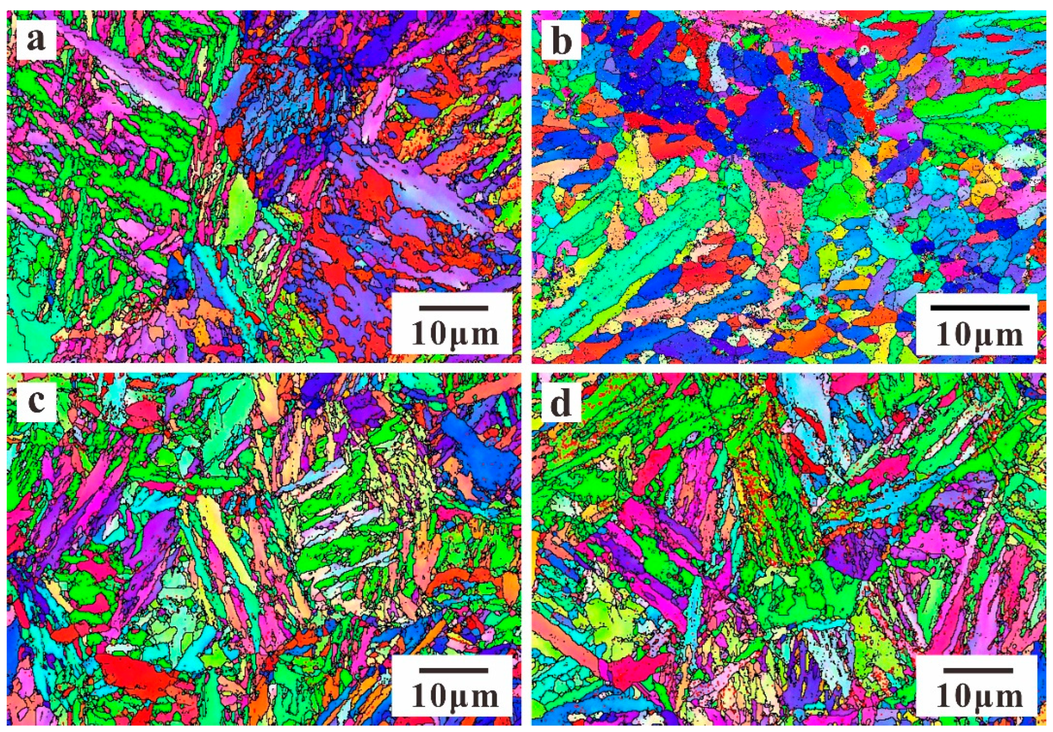
3.1. Microstructure

The EBSD microstructures of 35CrMo steel with four heat-treatment procedures are shown in Figure 2. It can be seen that Q specimen contains many lath martensites and some retained austenites. The microstructure of QT200 specimen consists of plate shaped tempered martensites and some retained austenites. Both QT400 and QT500 specimens display the uniform microstructures of tempered troostite, as shown in Figure 2c,d.

3.2. Tensile Behaviors

The tensile properties of 35CrMo with different heat-treatment procedures are provided in Figure 3. The tensile properties of 35CrMo steel at different tempering temperatures are listed in Table 3. As can be seen from Figure 3b, with the tempering temperature increasing, the tensile strength (σb) successively decreases; besides, the yield strength (σy) slowly increases at first and then decreases, which are in agreement with the cases of other steels [19,31]. It is observed that the percentage reduction of area (Z) and elongation after fracture (A) increase in different degrees with increasing tempering temperature as shown in Figure 3c. Figure 3d gives relations of the elongation after fracture and the percentage reduction of area versus the tensile strength of 35CrMo steel. As the tensile strength increases, the elongation after fracture and the percentage reduction of area decrease in varying degrees. This is consistent with the inverse relation between strength and ductility for lots of metals [19].
The macroscopic fractographies of tensile specimens for 35CrMo steel are shown in Figure 4. It can be seen that the tensile specimens with different tempering temperatures have significant necking phenomena. With the increase of tempering temperature, the area ratio of fiber zone (the ratio of the fiber zone area to the fracture surface area) gradually decreases, and the area ratio of shear lip first increases and then decreases slightly. Q and QT200 specimens have no obvious radial pattern, as shown in Figure 4a,b. QT400 and QT500 specimens have radial zone, the area ratio of radial zone increases and radial pattern becomes pronounced with the increase of tempering temperature, as shown in Figure 4c,d.
Tensile fractographies in the fiber zone for 35CrMo steel are magnified in Figure 5. It can be seen that the fiber zones of these specimens are mainly composed of dimples with different sizes, implying the typical ductile fracture modes. Besides, few microcracks and some larger voids can also be seen from the figure. The formation of microcracks and voids in the fiber zone can be attributed to the transition of the stress states of the specimen from uniaxial to triaxial due to the necking of specimens. The plastic deformation at the axial center of the specimen is difficult to continue with the effect of triaxial stress, so that the stress concentration occurs at the inclusions or second-phase particles, where the voids eventually nucleate and grow. Consequently, the sizes of microcracks or voids are closely related to inclusions or second-phase particles. It can be noted from Figure 5 that the sizes of microcracks and voids increase with the increase of tempering temperature, and such a similar situation has also appeared in high-strength, high ductility steels [32]. It can be concluded that the strength and toughness affect the behaviors of inclusions or second-phase particles. This seems to be consistent with the effect of tensile loads on the behaviors of inclusion and second-phase particles at elevated temperature, which is due to the transformation of tensile properties affected by high temperature [33].

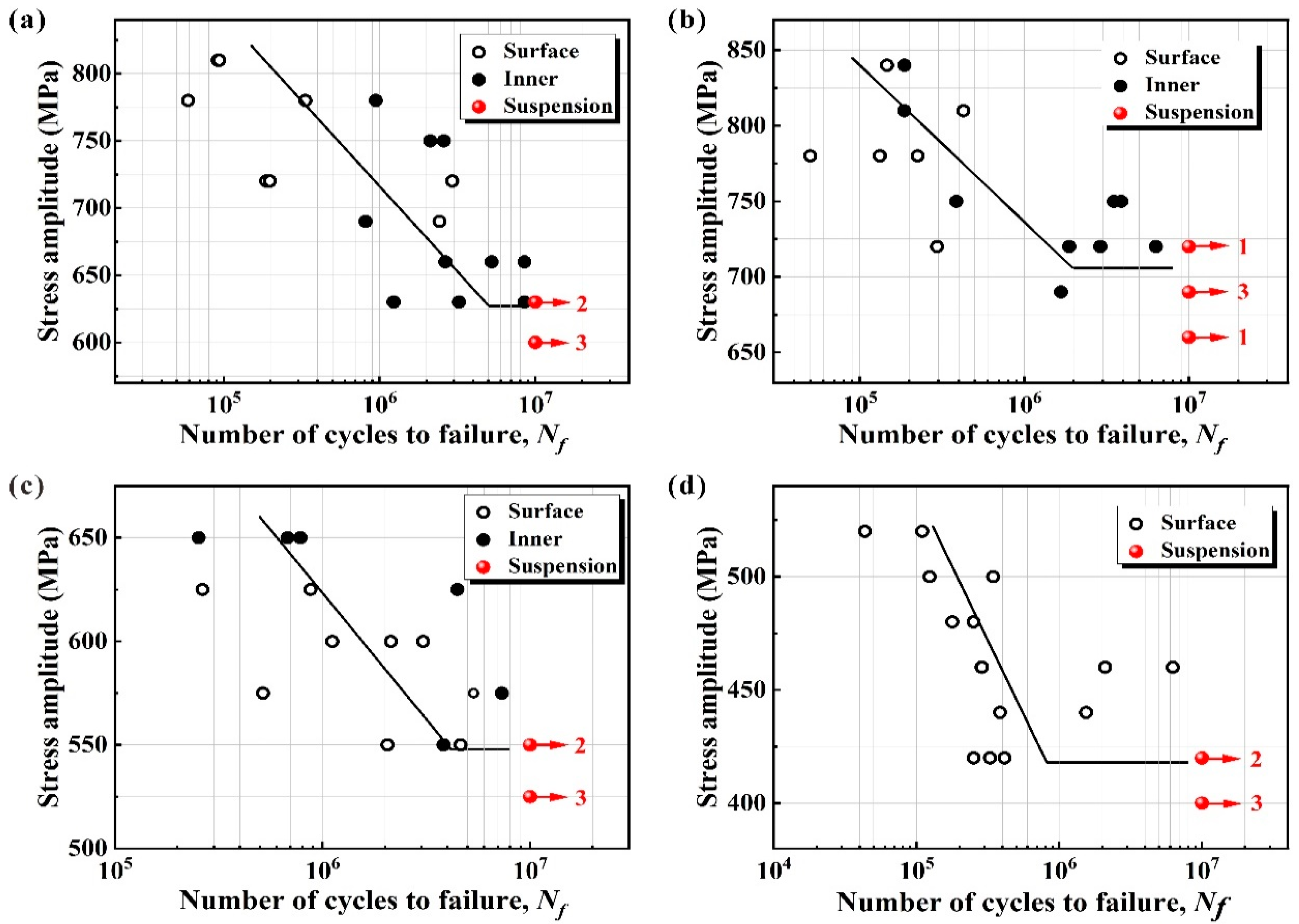
3.3. High-Cycle Fatigue Behaviors

The S–N curves of 35CrMo steel under different heat treatments are shown in Figure 6a. The fatigue properties of 35CrMo steel at different tempering temperatures are listed in Table 4. Obviously, QT200 specimens have the best fatigue resistance. The fatigue strengths (σw) increase first and then decrease with the increase of tensile strengths (Figure 6b), which were also found in many other materials [19,34]. The Basquin equations for these materials are as below (Equations (2)–(5)):
σ a = 2040.42 ( 2 N f ) 0.073 ,   for   Q
σ a = 1718.57 ( 2 N f ) 0.058 ,   for   QT 200
σ a = 2261.03 ( 2 N f ) 0.089 ,   for   QT 400
σ a = 2539.02 ( 2 N f ) 0.126 ,   for   QT 500
In Equations (2)–(5), the obtained fatigue strength coefficient σf′ and fatigue strength exponents b are reported for the considered cases. The relations of fatigue parameters (σf′ and b) vs. the tensile strengths are shown in Figure 6c,d. It can be seen that the increasing and decreasing trends of them are opposite and both curves have extreme values at data of QT200 specimens. This is inconsistent with the trend of steels for very high cycle fatigue (VHCF) [27]. Some researchers pointed out that HCF and VHCF behaviors are different for the same materials [22,35,36]. Therefore, it is essential to study the variations of the fatigue strength coefficient and exponent in a wide strength range from the perspective of HCF.
The fatigue strength coefficient and the fatigue strength exponent are mainly affected by strengthening mechanisms and damage mechanisms of materials respectively [27]. In order to understand the variation trends of fatigue strength coefficient and exponent for 35CrMo steel, it is necessary to study the fracture mechanism of failed specimens. The fatigue source regions of failed specimens with different heat-treatment procedures were observed by SEM. According to different crack initiation mechanisms, these specimens could be divided into five categories, as shown in Figure 7, such as (a) surface scratch; (b) surface inclusion; (c) subsurface inclusion, representing the inclusion whose distance from the surface is less than its own size in this paper; (d) inner inclusion, representing the inclusion whose distance from the surface is greater than its size; and (e) micro-facet comprising numerous small convex and concave, representing the trace of plastic deformation caused by non-inclusion crack [37,38]. For the convenience of statistics, some researchers have summarized the fatigue crack initiation sites into two types, namely, surface and inner [19]. Inner represents inner inclusion and micro-facet, and surface scratch, surface inclusion, and subsurface inclusion are classified as surface, as shown in Figure 8.
The two types of failed specimens have been indicated in the S–N curves, as shown in Figure 9. In the figure, the circles represent the failed specimens with cracks initiated on the surface and the solid circles represent the cracks initiated inside. It is found that the specimens with initiation of inner cracks are generally loaded at low-stress levels and have high fatigue life, which can be clearly seen in Figure 9a,b. The same situation has also been found by some other researchers [13,22,37]. Under high applied stress amplitude, the surface defects and processing defects are the obvious weak zones, since the plastic deformation preferentially occurs at surface due to lack of constrain. The locally accumulated plastic strain caused by high stress concentration at the surface defects and processing defect will induce crack initiation. On the other hand, when the lower stress amplitude is applied, the locally accumulated plastic strain over those surface defects becomes weaker; at this time, some interior inclusions may have the potential to compete with those defects. Since the inner area of a cross section is generally much larger than the outer surface layer area, the probability for larger inclusions or harmful inclusions emerging in the inner area is definitely greater than that in the surface area. If so, the fatigue cracks may initiate from internal inclusions at the low stress amplitude.
From Figure 9, one can see that most of the failure samples for Q begin to fracture from the inside, and the number of such failed samples gradually decreases with the increase of tempering temperature of heat-treatment procedures. Until the tempering temperature reaches 500 °C, all the failed specimens begin to fracture on the surface. Figure 10a shows the relations between the ratios of surface/inner fatigue crack initiation sites (the ratios of the number of failures originating from the surface/inner to the total number of failures) and yield strengths. It can be seen that the ratio of surface initiation cracks decreases with the increase of yield strength. In other words, as the yield strength decreases, the trend of surface fatigue crack initiation increases. It is understood with lower yield strength, the severe locally accumulated plastic deformation will easily result in the surface defects as mentioned above. Furthermore, it can be roughly inferred from the figure that cracks will initiate from the surface for the specimens with yield strengths below 1200 MPa. The ratio of inner cracks will continue to increase when the yield strengths of the samples are higher than 1500 MPa. To sum up, it can be said that the yield strength affects the ratio of fatigue crack initiation site to a certain extent.
Wang et al. [39] have concluded that the transition from surface to subsurface crack initiation has a significant effect on the slope of S–N curve. As an extension, the intercepts and slopes of S–N curves (fatigue strength coefficient and exponent of Basquin equation) are related to fatigue crack initiation sites, as shown in Figure 10b. It can be seen that the fatigue strength coefficient decreases and the fatigue strength exponent increases with the increasing ratio of the inner crack site. Therefore, different ratios of crack initiation sites affect the fatigue strength coefficient and exponent of Basquin equation to a certain extent. The reason can be found from the distribution characteristics of different crack initiations sites in Figure 9 and the relations in Figure 10b. Combined with the above conclusions that the yield strength affects the ratio of fatigue crack initiation site and the cracking position affects the fatigue strength coefficient and exponent, it can be said that the fatigue strength coefficient and exponent are indirectly influenced by the yield strength.

3.4. Prediction of Fatigue Strength

To predict fatigue strength by Basquin equation, some parameters are necessary to figure out. As shown in Figure 11a, the fatigue strength σw of a material can be determined by the fatigue strength coefficient, exponent, and the life of knee point Nk in the S–N curve. The knee point is the intersection of the curve fitted by the group method and the fatigue strength calculated by the staircase method. Obviously, the knee point is also a necessary parameter to predict fatigue strength.
The logarithmic form of Basquin equation for S–N curves can be obtained,
lg σ a = b lg ( 2 N f ) + lg σ f
If Nk is determined, the fatigue strength prediction equation can be written as
lg σ w = b lg ( 2 N k ) + lg σ f
Based on the above discussion, σf and b are linearly fitted with the yield strength, and the error bands are within the 10% and 5%, respectively, as shown in Figure 11b,c. In addition, the knee point is also fitted with the yield strength for the unification of variables and convenience of calculation. They have a quadratic relation with only 1% error band, as shown in Figure 11d. This is the relation between the intersection of the two lines and the yield strength, which has no practical significance. The fitting equations can be expressed in linear and quadratic equations as below, respectively,
σ f = m σ y + n
b = u σ y + v
lg ( 2 N k ) = x σ y 2 + y σ y + z
Substituting Equations (8)–(10) into Equation (7), a new relation can be obtained,
lg σ w = ( u σ y + v ) ( x σ y 2 + y σ y + z ) + lg ( m σ y + n )
where, m, n, u, v, x, y, and z are the material constants, which can be obtained by data fitting.
For 35CrMo steel, the constants have been fitted and the fatigue strength prediction formula can be expressed as follows,
lg σ w = ( 2.193 × 10 4 σ y 0.382 ) ( 1.987 × 10 5 σ y 2 + 5.422 × 10 2 σ y 30.029 ) + lg ( 2.542 σ y + 5564.850 )
The results of fatigue strength prediction are shown in Figure 12, and it can be seen that the errors of this fatigue prediction equation are less than 10%.

4. Conclusions

The fatigue fracture morphologies and HCF properties of 35CrMo steel specimens with different tensile strengths were studied. The main conclusions can be summarized as below:
(1)
With the increase of tempering temperature, martensite is gradually decomposed and the tensile strength decreases, but the yield strength and fatigue strength increase at first and then decrease. QT200 specimens have the best fatigue performance;
(2)
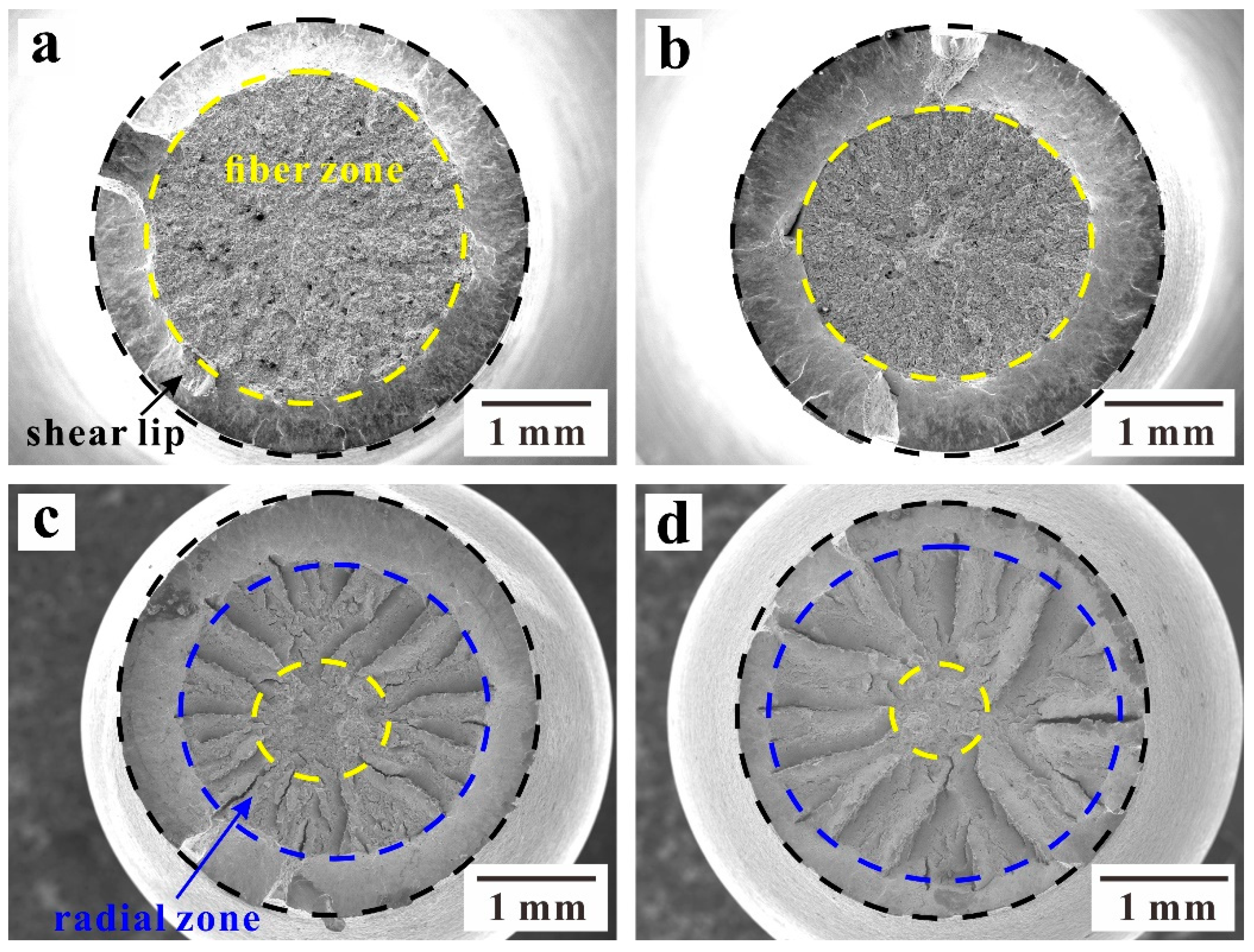
To some extent, the yield strength affects the ratio of crack initiation site for a specimen, and the crack initiation site affects the fatigue strength coefficient and fatigue strength exponent. Therefore, the yield strength affects the change of fatigue strength coefficient and fatigue strength exponent, and they have a linear relation for HCF tests of 35CrMo steel;
(3)
A fatigue strength prediction method based on the damage mechanisms and Basquin equation was proposed. In this way, the values of fatigue strength coefficient, fatigue strength exponent, and knee point can be expressed by yield strength. This method can effectively predict the HCF strength of 35CrMo steel. The fatigue strength coefficient, fatigue strength exponent, and knee point are affected by many factors, and it is still necessary to further explore whether this method is suitable for other materials.

Author Contributions

Conceptualization, J.P. and Z.Z.; Funding acquisition, M.Y., J.P., D.H. and Z.Z.; Investigation, C.G.; Methodology, C.G., S.L., J.P., and X.L.; Project administration, M.Y., and D.H.; Resources, M.Y., and D.H.; Writing-original draft, C.G.; Writing—review & editing, J.P., S.L., X.L., and Z.Z. All authors have read and agreed to the published version of the manuscript.

Funding

This research was funded by project entitled “Research on Lifetime Prediction of Non-rotating Parts of Pump Turbine Unit Based on Rotor-Stator Interaction (RSI), Fluid-Structure Coupling and Fracture Mechanics” under Grant. No. 022200KK52180006, National Natural Science Foundation of China (NSFC) under Grant. No. 51871224, Natural Science Foundation of Liaoning Province under Grant. No. 20180550880.

Institutional Review Board Statement

The study did not require ethical approval.

Informed Consent Statement

Not applicable.

Data Availability Statement

Not applicable.

Acknowledgments

The authors would like to thank Z. K. Zhao and H. Y. Zhang for their help of the fatigue experiment and SEM observations.

Conflicts of Interest

The authors declare no conflict of interest.

References

  1. Tanaka, K.; Shimonishi, D.; Nakagawa, D.; Ijiri, M.; Yoshimura, T. Stress relaxation behavior of cavitation-processed Cr-Mo steel and Ni-Cr-Mo steel. Appl. Sci. 2019, 9, 299. [Google Scholar] [CrossRef] [Green Version]
  2. Raj, B.; Choudhary, B.; Raman, R.S. Mechanical properties and non-destructive evaluation of chromium–molybdenum ferritic steels for steam generator application. Int. J. Press. Vessel. Pip. 2004, 81, 521–534. [Google Scholar] [CrossRef]
  3. Ma, K.; Zheng, J.; Hua, Z.; Gu, C.; Zhang, R.; Liu, Y. Hydrogen assisted fatigue life of Cr–Mo steel pressure vessel with coplanar cracks based on fatigue crack growth analysis. Int. J. Hydrogen Energy 2020, 45, 20132–20141. [Google Scholar] [CrossRef]
  4. Zhang, J.; Lu, L.; Wu, P.; Ma, J.; Wang, G.; Zhang, W. Inclusion size evaluation and fatigue strength analysis of 35CrMo alloy railway axle steel. Mater. Sci. Eng. A 2013, 562, 211–217. [Google Scholar] [CrossRef]
  5. Lv, Y. Influence of laser surface melting on the micropitting performance of 35CrMo structural steel gears. Mater. Sci. Eng. A 2013, 564, 1–7. [Google Scholar] [CrossRef]
  6. Takemasu, T.; Koide, T.; Shinbutsu, T.; Sasaki, H.; Takeda, Y.; Nishida, S. Effect of Surface Rolling on Load Bearing Capacity of Pre-alloyed Sintered Steel Gears with Different Densities. Procedia Eng. 2014, 81, 334–339. [Google Scholar] [CrossRef] [Green Version]
  7. Shi, H.Q.; Ding, Y.; Ma, L.Q.; Shen, X.D. Corrosion Failure Analysis of 35CrMo Bolt in Wet Hydrogen Sulfide Environment. Appl. Mech. Mater. 2013, 291–294, 2605–2609. [Google Scholar] [CrossRef]
  8. Gaur, V.; Doquet, V.; Persent, E.; Roguet, E. Effect of biaxial cyclic tension on the fatigue life and damage mechanisms of Cr–Mo steel. Int. J. Fatigue 2016, 87, 124–131. [Google Scholar] [CrossRef]
  9. Zheng, X.T.; Wu, K.W.; Wang, W.; Yu, J.Y.; Xu, J.M.; Ma, L.W. Low cycle fatigue and ratcheting behavior of 35CrMo structural steel at elevated temperature. Nucl. Eng. Des. 2017, 314, 285–292. [Google Scholar] [CrossRef]
  10. Hua, Z.; Zhang, X.; Zheng, J.; Gu, C.; Cui, T.; Zhao, Y.; Peng, W. Hydrogen-enhanced fatigue life analysis of Cr–Mo steel high-pressure vessels. Int. J. Hydrogen Energy 2017, 42, 12005–12014. [Google Scholar] [CrossRef]
  11. Wei, W.; Feng, Y.; Han, L.; Zhang, Q.; Zhang, J. Cyclic hardening and dynamic strain aging during low-cycle fatigue of Cr-Mo tempered martensitic steel at elevated temperatures. Mater. Sci. Eng. A 2018, 734, 20–26. [Google Scholar] [CrossRef]
  12. Ogawa, Y.; Matsunaga, H.; Yamabe, J.; Yoshikawa, M.; Matsuoka, S. Fatigue limit of carbon and Cr Mo steels as a small fatigue crack threshold in high-pressure hydrogen gas. Int. J. Hydrogen Energy 2018, 43, 20133–20142. [Google Scholar] [CrossRef]
  13. Zhang, J.; Lu, L.; Shiozawa, K.; Zhou, W.; Zhang, W. Effect of nitrocarburizing and post-oxidation on fatigue behavior of 35CrMo alloy steel in very high cycle fatigue regime. Int. J. Fatigue 2011, 33, 880–886. [Google Scholar] [CrossRef]
  14. Samant, S.; Pandey, V.; Singh, I.; Singh, R. Effect of double austenitization treatment on fatigue crack growth and high cycle fatigue behavior of modified 9Cr–1Mo steel. Mater. Sci. Eng. A 2020, 788, 139495. [Google Scholar] [CrossRef]
  15. Zhao, Z.L.; Li, C.F. Metal Technology; Beijing Institute of Technology Press: Beijing, China, 2019. [Google Scholar]
  16. Shaeri, M.; Saghafian, H.; Shabestari, S. Effect of heat treatment on microstructure and mechanical properties of Cr–Mo steels (FMU-226) used in mills liner. Mater. Des. 2012, 34, 192–200. [Google Scholar] [CrossRef]
  17. Laxmi, B.; Sharma, S.; Pk, J.; Hegde, A. Quenchant oil viscosity and tempering temperature effect on mechanical properties of 42CrMo4 steel. J. Mater. Res. Technol. 2021, 16, 581–587. [Google Scholar] [CrossRef]
  18. Gao, C.; Yang, M.; Pang, J.; Li, S.; Zou, M.; Li, X.; Zhang, Z. Abnormal relation between tensile and fatigue strengths for a high-strength low-alloy steel. Mater. Sci. Eng. A 2021, 832, 142418. [Google Scholar] [CrossRef]
  19. Pang, J.; Li, S.; Wang, Z.; Zhang, Z. General relation between tensile strength and fatigue strength of metallic materials. Mater. Sci. Eng. A 2013, 564, 331–341. [Google Scholar] [CrossRef]
  20. Pang, J.C.; Li, S.X.; Wang, Z.G.; Zhang, Z.F. Relations between fatigue strength and other mechanical properties of metallic materials. Fatigue Fract. Eng. Mater. Struct. 2014, 37, 958–976. [Google Scholar] [CrossRef]
  21. Murakami, Y. Metal Fatigue: Effect of Small Defects and Nonmetallic Inclusions, 2nd ed.; Elsevier Ltd.: Amsterdam, The Netherlands, 2019. [Google Scholar]
  22. Li, S.X. Effects of inclusions on very high cycle fatigue properties of high strength steels. Int. Mater. Rev. 2012, 57, 92–114. [Google Scholar] [CrossRef]
  23. Murakami, Y.; Takagi, T.; Wada, K.; Matsunaga, H. Essential structure of S-N curve: Prediction of fatigue life and fatigue limit of defective materials and nature of scatter. Int. J. Fatigue 2021, 146, 106138. [Google Scholar] [CrossRef]
  24. Liu, Q.; Zhu, G.; Pang, J.; Liu, F.; Li, S.; Guo, C.; Jiang, A.; Zhang, Z. High-cycle fatigue properties prediction and damage mechanisms of RuT400 compacted graphite iron at different temperatures. Mater. Sci. Eng. A 2019, 764, 138248. [Google Scholar] [CrossRef]
  25. Liu, Y.; Li, Y.; Li, S.; Yang, Z.; Chen, S.; Hui, W.; Weng, Y. Prediction of the S–N curves of high-strength steels in the very high cycle fatigue regime. Int. J. Fatigue 2010, 32, 1351–1357. [Google Scholar] [CrossRef]
  26. Murakam, Y.; Nomoto, T.; Ueda, T. Factors influencing the mechanism of superlong fatigue failure in steels. Fatigue Fract. Eng. Mater. Struct. 1999, 22, 581–590. [Google Scholar] [CrossRef]
  27. Duan, Q.Q.; Pang, J.C.; Zhang, P.; Li, S.X.; Zhang, Z.F. Quantitative relations between S-N curves parameters and tensile strength for two steels: AISI 4340 and SCM 435. Res. Rev. J. Mater. Sci. 2018, 6, 1–16. [Google Scholar]
  28. Shiozawa, K.; Lu, L. Very high-cycle fatigue behaviour of shot-peened high-carbon-chromium bearing steel. Fatigue Fract. Eng. Mater. Struct. 2002, 25, 813–822. [Google Scholar] [CrossRef]
  29. Petit, J.; Sarrazin-Baudoux, C. An overview on the influence of the atmosphere environment on ultra-high-cycle fatigue and ultra-slow fatigue crack propagation. Int. J. Fatigue 2006, 28, 1471–1478. [Google Scholar] [CrossRef]
  30. Lee, Y.L.; Pan, J.; Hathaway, R.B.; Barkey, M.E. Fatigue Testing and Analysis: Theory and Practice; Butterworth-Heinemann: Waltham, MA, USA, 2005. [Google Scholar]
  31. Gan, Y.; Tian, Z.L.; Dong, H.; Feng, D.; Xin, X.L. China Materials Engineering Canon Steel Materials Engineering; Chemical Industry Press: Beijing, China, 2005; Volume 3. [Google Scholar]
  32. Zhao, N.; Zhao, Q.; He, Y.; Liu, R.; Liu, W.; Zheng, W.; Li, L. Strengthening-toughening mechanism of cost-saving marine steel plate with 1000 MPa yield strength. Mater. Sci. Eng. A 2021, 831, 142280. [Google Scholar] [CrossRef]
  33. Xiao, B.; Xu, L.; Zhao, L.; Jing, H.; Han, Y. Tensile mechanical properties, constitutive equations, and fracture mechanisms of a novel 9% chromium tempered martensitic steel at elevated temperatures. Mater. Sci. Eng. A 2017, 690, 104–119. [Google Scholar] [CrossRef]
  34. Pang, J.C.; Duan, Q.Q.; Wu, S.D.; Li, S.X.; Zhang, Z.F. Fatigue strengths of Cu-Mg alloy with high tensile strengths. Scr. Mater. 2010, 63, 1085–1088. [Google Scholar] [CrossRef]
  35. Bayraktar, E.; Garcias, I.; Bathias, C. Failure mechanisms of automotive metallic alloys in very high cycle fatigue range. Int. J. Fatigue 2006, 28, 1590–1602. [Google Scholar] [CrossRef]
  36. Li, Z.D.; Zhou, S.T.; Yang, C.F.; Yong, Q.L. High/very high cycle fatigue behaviors of medium carbon pearlitic wheel steels and the effects of microstructure and non-metallic inclusions. Mater. Sci. Eng. A 2019, 764, 138208. [Google Scholar] [CrossRef]
  37. Gao, G.; Liu, R.; Wang, K.; Gui, X.; Misra, R.D.K.; Bai, B. Role of retained austenite with different morphologies on sub-surface fatigue crack initiation in advanced bainitic steels. Scr. Mater. 2020, 184, 12–18. [Google Scholar] [CrossRef]
  38. Gui, X.L.; Gao, G.H.; An, B.F.; Misra, R.D.K.; Bai, B.Z. Relationship between non-inclusion induced crack initiation and micro-structure on fatigue behavior of bainite/martensite steel in high cycle fatigue/very high cycle (HCF/VHCF) regime. Mater. Sci. Eng. A 2021, 803, 140692. [Google Scholar] [CrossRef]
  39. Wang, Q.Y.; Bathias, C.; Kawagoishi, N.; Chen, Q. Effect of inclusion on subsurface crack initiation and gigacycle fatigue strength. Int. J. Fatigue 2002, 24, 1269–1274. [Google Scholar] [CrossRef]
Figure 1. Configurations and dimensions of specimens tested for tensile (a) and fatigue (b) properties. (Unit: mm).
Metals 12 00688 g001
Figure 2. EBSD microstructures for 35CrMo steel with four heat-treatment procedures. (a) Q, (b) QT200, (c) QT400, and (d) QT500.
Metals 12 00688 g002
Figure 3. Tensile properties of 35CrMo steel. (a) Tensile engineering stress-strain curves; (b,c) the relation between strengths (tensile and yield strengths), percentages (elongation after fracture and percentage reduction of area), and tempering temperature; and (d) relations of percentages vs. tensile strength.
Metals 12 00688 g003
Figure 4. The macroscopic fractographies of tensile samples for 35CrMo steel processed at different tempering temperatures. (a) Untampered, (b) 200 °C, (c) 400 °C, and (d) 500 °C.
Metals 12 00688 g004
Figure 5. Tensile fractographies in the fiber zone for 35CrMo steel processed at different tempering temperatures. (a) Untampered, (b) 200 °C, (c) 400 °C, and (d) 500 °C.
Metals 12 00688 g005
Figure 6. (a) Relations between stress amplitude and fatigue life (S–N curves), (b) the relation between tensile and fatigue strengths, (c) the relation between fatigue strength coefficient and tensile strength, and (d) the relation between fatigue strength exponent and tensile strength.
Metals 12 00688 g006
Figure 7. Fatigue crack initiation morphologies. (a) Surface scratch, (b) surface inclusion, (c) subsurface inclusion, (d) inner inclusion, and (e,f) micro-facet.
Metals 12 00688 g007
Figure 8. Schematic diagram of crack initiation site.
Metals 12 00688 g008
Figure 9. S–N curves for the specimens of Q (a), QT200 (b), QT400 (c) and QT500 (d).
Metals 12 00688 g009
Figure 10. (a) The relation between the ratios of fatigue crack initiation sites and yield strength, and (b) relations of the fatigue strength coefficient and exponent vs. ratio of inner crack site.
Metals 12 00688 g010
Figure 11. The fatigue strength prediction model. (a) The schematic illustration of S–N curves, (b) the linear relation between σf′ and σy, (c) the linear relation between b and σy, and (d) the relation of lg(2Nk) and σy.
Metals 12 00688 g011
Figure 12. The calculated vs. experimental values for fatigue strength.
Metals 12 00688 g012
Table 1. Chemical composition of 35CrMo/%.
CSiMnCrMoPSFe
0.350.350.761.130.20<0.005<0.001Balance
Table 2. Heat-treatment procedures of 35CrMo steel.
SamplesQuenchingTempering
QPreheating to 860 °C for 30 min and quenching in oilUntempered
QT200200 °C tempering for 90 min
QT400400 °C tempering for 90 min
QT500500 °C tempering for 90 min
Table 3. Tensile properties for 35CrMo steel processed at different tempering temperatures.
Sampleσb/MPaσy/MPaZ/%A/%
Q1977138033.2010.80
QT2001891148747.6612.05
QT4001566135251.8412.10
QT5001261117058.5316.20
Table 4. Fatigue properties and S–N curves parameters for 35CrMo steel processed at different tempering temperatures.
Sampleσw/MPaσfb
Q6272040.42−0.073
QT2007061718.57−0.058
QT4005482261.03−0.089
QT5004182539.02−0.126
Publisher’s Note: MDPI stays neutral with regard to jurisdictional claims in published maps and institutional affiliations.

