Article

Impact of Cladding Technology on Residual Stresses within the Renovation of High Pressure Die Casting Molds

1
Department of Industrial Automation and Mechatronics, Faculty of Mechanical Engineering, Technical University of Košice, 042 00 Košice, Slovakia
2
Department of Technology, Materials and Computer Aided Production, Faculty of Mechanical Engineering, Technical University of Košice, 042 00 Košice, Slovakia
3
Department of Applied Mechanics and Mechanical Engineering, Faculty of Mechanical Engineering, Technical University of Košice, 042 00 Košice, Slovakia
*
Author to whom correspondence should be addressed.
Metals 2022, 12(3), 388; https://doi.org/10.3390/met12030388
Submission received: 1 January 2022 / Revised: 20 February 2022 / Accepted: 21 February 2022 / Published: 23 February 2022
(This article belongs to the Special Issue Renovation of Parts to Save Metals)

Abstract

:
Residual stresses significantly affect the overall lifetime of constructions. The main disadvantage of residual stresses is that their effect and magnitude is not evident at first sight and can only be reliably determined using experimental methods. The experiment aimed to find out how much the cladding technology affects the residual stresses within the renovation of high pressure die casting molds. A total of four samples were prepared by different cladding techniques and with varying thicknesses of the result layer. The samples were then annealed and mechanically treated. Finally, the hole drilling method was applied to determine the residual stresses in the samples. The results point to more significant differences in the levels of residual stresses, which were determined in the subsurface layers.

1. Introduction

High Pressure Die Casting (HDPC) is a technological process widely used to produce complex aluminium castings, mainly associated with the automotive industry. In this process, molten metal with a temperature of 670–710 °C is injected into the cavities of the molds at filling speeds of 30–100 m/s, under pressures ranging from 40 to 80 MPa.
The service life of injection molds is negatively affected by a combination of tribodegradation factors. Cyclic loading by high pressures, in combination with the corrosive properties of liquid aluminum, leads to aluminization or oxidation of the mold surface. At the same time, thermal fatigue of the surfaces occurs, followed by their cracking (Figure 1). In the vicinity of the ejectors, the surfaces are also stressed by adhesive–erosive combined wear. High melt flow rates of aluminum alloys (up to 120 m/s−1), high pressures (up to 120 MPa), and high maximum surface temperatures of mold parts (up to 550 °C) lead to erosion, abrasion, corrosion, and thermal fatigue of the mold. This issue is addressed in publications [1,2,3,4,5].
After several thousand cycles, the material loss in the injection channels occurs in the high-pressure casting molds. This is due to the interaction of adhesive–erosive and corrosive effects, which leads to the dissolution of the matrix (Figure 2). Before oxidation or aluminization, the mold surfaces are protected by lubricating coatings. These can still be removed in areas of high erosive stress by the pressure of the flowing metal [6,7].
The adhesion of aluminum to the mold surfaces is manifested by the partial or complete adhesion of the cast material to the metal matrix. The cause is either the chemical interaction of the aluminum alloy and the metal matrix or the infiltration of aluminum into the surface of the matrix through cracks caused by cyclic thermal stress. Such cracking results from thermal fatigue, which reduces the strength of the mold material as the cycle of heating and cooling is continuously repeated. Fluctuations in thermal and mechanical stress initiate the growth of microcracks on the surface, followed by the gradual peeling of particles from the surface of the molds, which is documented in sources [5,6,7,8].
The lifetime of the die matrices made of steel alloys is approximately 100,000 cycles and can be increased by heat treatment, thin coating, or cladding [9]. Publications [10,11,12] investigate the effects of different cladding techniques.
The submitted article presents an experimental analysis of different cladding techniques used to renovate the functional surfaces of molds for high pressure die casting of aluminum alloys. In the experiment, four samples with different cladding techniques were prepared, then the samples were heat treated and machined. Residual stress levels were determined on the samples prepared in this way by the hole drilling method, which is one of the semi-destructive experimental methods, and the authors have extensive experience with it [13,14,15,16].
There are also attempts to analyze residual stresses using simulation methods [17,18,19,20], though experimental methods are still more reliable. The non-destructive X-ray diffraction method is often used to analyze residual stresses, but it has certain disadvantages compared with destructive or semi-destructive methods. The use of the X-ray diffraction method to determine the residual stresses in the surfacing layer is described in [21]. The analysis of the residual stresses by hole drilling method in explosive welding is discussed in [22]. The determination of the residual stresses using the electroslag strip cladding method is discussed in [23]. Finally, the combination of the determination of residual stresses by finite element method and the hole drilling method is described in [24].

2. Materials and Methods

A total of two different materials were used in the experiment-base and added cladding layer, which was applied by four different techniques.
The base material for all samples with a same thickness was chrome-molybdenum-silicon-vanadium steel 1.2343, DIN-X38CrMoV51 (voestalpine High Performance Metals Germany, Düsseldorf, Germany), with a hardness of 50 HRC, which is used for high pressure casting molds. Material has good thermal conductivity, high toughness, and is hot cracking resistant. Its chemical composition, analyzed by the Belec Compact Port spectrum chemical analyzer (Belec Spektrometrie Opto-Elektronik GmbH, Georgsmarienhütte, Germany), is shown in Table 1. The mechanical properties defined by the manufacturer are shown in Table 2 [25,26].
A wire from Uddeholm under the trade name Dievar (1.2344, DIN-X40CrMoV51) (voestalpine High Performance Metals Germany, Düsseldorf, Germany) with a diameter of ø 1.2 mm and a hardness of 51 HRC was applied for the cladding layers. Steel 1.2344 has high heat and wear resistance, good toughness, thermal conductivity, and hot cracks resistance [27]. The chemical composition of the used additive material and its mechanical properties are shown in Table 3 and Table 4.

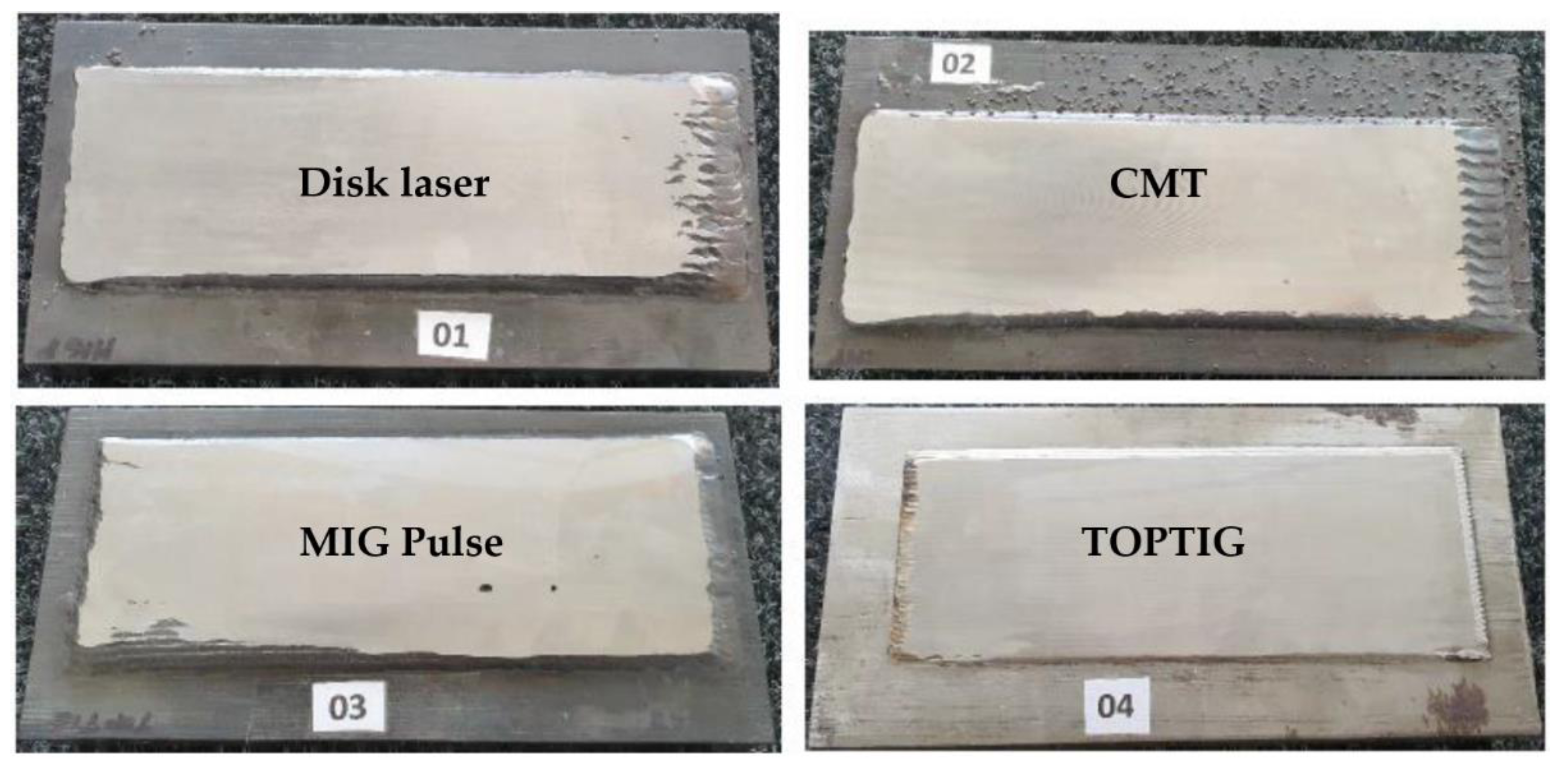
2.1. Cladding Technologies

Cladding processes were conducted at a robotic workplace, thus eliminating the influence of the human factor on the quality of the realized cladding layer [28]. For the production of experimental samples, progressive cladding technologies were chosen that minimize the heat input into the cladding layer, resp. to subsurface areas. The following cladding technologies were used for the production of experimental samples:
  • Disk laser
Laser cladding technology was the first to be used [29]. This energy beam method is increasingly being applied to restore the functional areas of molds. Its advantage is minimizing heat introduced into the material and making minor, local repairs. In addition, the automated mode allows for achieving a high quality of cladding layers. A TruDisk 4002 (TRUMPF Pvt. Ltd., Pune-Maharashtra, India) solid-state disk laser with BEO D70 focusing optics mounted on a 6-axis robot FANUC M-710iC/50 (FANUC Slovakia s.r.o, Nitra, Slovakia) [30] with the following parameters was used to create a Sample marked 01:
  • Focal length 200 mm,
  • Laser light cable diameter 400 µm,
  • Laser power 1.8 kW,
  • Cladding speed 10 mm/s,
  • Focusing + 6 mm,
  • Wire feed speed 70 cm/min,
  • Shielding gas flow rate Ar 30 L/min,
  • The cladding was performed without preheating.
  • CMT technology
CMT stands for cold metal transfer, and the method is based on electric arc welding in a protective gas atmosphere, the energy in this process is precisely supplied to the joint [31,32]. A Fronius Trans Puls Synergic 3200 welding source with the following parameters was used to prepare Sample 02:
  • Cladding current 224 A,
  • Cladding voltage 23.2 V,
  • Wire feed speed 6.5 m/min,
  • Cladding speed 8 mm/s,
  • Arc length correction 15%,
  • Dynamics correction 0.3,
  • Shielding gas flow rate Ar 15 L/min,
  • Moving the welding torch between cladded caterpillar 5.5 mm,
  • Distance between torch and surface 14 mm.
The claddings were made in two layers in 13 caterpillar-shaped welding traces. Base material was preheated to 300 °C before layers were applied.
  • MIG Pulse
The Metal Inert Gas (MIG) Pulse cladding method uses a pulsed welding current, which minimizes metal spatter in the cladding area [33,34]. The cladding layer on Sample 03 was formed by a welding source Fronius TPS600i (Fronius International GmbH Sales International, Wels, Austria) [35] with the following parameters:
  • Cladding current 196 A,
  • Cladding voltage 23.8 V,
  • Wire feed speed 6,5 m/min,
  • Cladding speed 8 mm/s,
  • Arc length correction 3%,
  • Pulse/Dynamics correction 0/0,
  • Shielding gas flow rate Ar 30 L/min,
  • Moving the welding torch between cladded caterpillar 5 mm,
  • Distance between torch and surface 19 mm,
  • The base material was preheated to 300 °C before cladding.
  • TOPTIG
The TOPTIG method was developed to combine the quality and advantages of a small heat-affected zone characteristic of TIG welding [36], with the welding power of MIG technology, in automated welding. TOPTIG works on the principle of TIG technology. However, the wire is led to the tip of the non-melting tungsten electrode in an area with high heat input. The additive material melts into tiny droplets, similar to the MIG method.
The AirLiquide TOPTIG 220 DC (Air Liquide Welding Central Europe s.r.o, Lužianky, Slovakia) welding power source [37] was used for Sample 04, with the following parameters set:
  • Cladding current 200 A,
  • Cladding voltage 15 V,
  • Wire feed speed 1.2 m/min,
  • Cladding speed 5 mm/s,
  • Shielding gas flow rate Ar 15 L/min,
  • Pre-blow: 2.5 s; After-blow 8.5 s,
  • Tungsten electrode: type WLa 15, diameter ø 2.4 mm,
  • Overhang tungsten electrode 5 mm,
  • Distance between electrode and surface 5 mm,
  • Electrode movement between caterpillar 3 mm.
Prior to cladding, preheating to 300 °C was used with this technology.

2.2. Heat Treatment and Final Machining

In the next step, the prepared samples were heat treated. They were annealed at 610 °C for 2 h and then cooled in air. The onset to the desired temperature took 2 h and 20 min.
The resulting hardness of the claddings after heat treatment was 48 HRC. Hardness in the range of 44–48 HRC is recommended for steels intended for the production of aluminum injection molds. This hardness guarantees a suitable type of structure with the required toughness. It is tempered martensite called sorbitol, or a structure formed by bainite and martensite. Higher hardness values (above 48 HRC) in the contact area indicate incorrect heat treatment. For these medium-alloy steels with a carbon content above 0.35%, it would mean a predominant coarse-grained martensitic structure, and a higher proportion of carbide inclusions, which reduces the material’s toughness. That can lead to cracks during cyclic loading of the material. The hardness range 44–48 HRC is also suitable from the point of view of the machinability of the mold parts. Machining processes are performed on CNC machines (5-axis milling machines). Due to the required quality of aluminum castings, it is necessary to finish their surfaces by grinding and polishing. Therefore, the samples were subsequently processed by milling and grinding to the final shape (Figure 3).
The resulting average thicknesses of the cladding layers on the individual samples after treatment were:
  • Sample 01–4.3 mm,
  • Sample 02–4.5 mm,
  • Sample 03–1.1 mm,
  • Sample 04–1.8 mm.

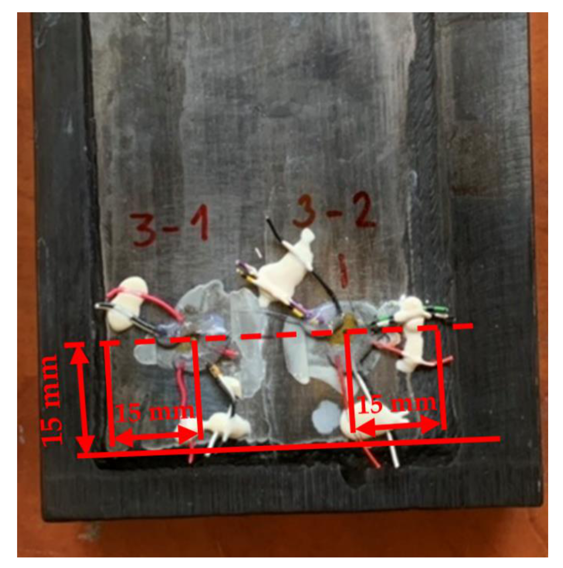
2.3. Residual Stress Measurement

Residual stresses on the prepared samples were determined using the hole drilling method. The hole drilling method’s principle consists of drilling a small blind hole in the center of the strain gauge and evaluating the released relative deformations in its vicinity. The resulting damage to the object under investigation is so small that it often does not affect its further use. Therefore, this method is suitable for measuring residual stresses on objects that will be further used. The advantage of this method is that it is easy to use in the field (outside the laboratory). The procedure for evaluating residual stresses is standardized and is given in ASTM E837 [38].
The SINT MTS-3000 measuring system (SINT Technology, Calenzano, Italy) was used in the experiment [39]. It is an automated measuring system that allows accurate measurement. A strain gauge HBM 1-RY61-1.5/120S was applied to the selected locations with X60 adhesive by HBM to record the relaxed deformations. The aim was to compare the levels of residual stresses in the cladding layer of individual samples. Location 1 and Location 2 were situated in one line about 15 mm from the edges of the cladding layer (Figure 4). Location 3 was in line with the locations 1 and 2 but outside the cladding area. Measurements in Location 3 were performed on samples 03 and 04, and their results are not discussed in this article. On samples 01 and 02, measurements were performed only on the cladding layer.
The SINT MTS 3000 measuring system was operated by the RESTAN control software (SINT Technology, Calenzano, Italy). The set parameters of all performed measurements were identical:
  • Drilling depth 2 mm,
  • Milling cutter diameter 1.8 mm,
  • Milling cutter suitable for hard samples with the designation 1-SINTCTT/1,
  • Number of realized measuring steps 20,
  • K-gauge factor of the used strain gauge rosette 1-RY61-1.5/120S k = 1.92.
After setting all the parameters, the SINT MTS 3000 measuring system was centered precisely above the center of the strain gauge, using a built-in microscope. Subsequently, the milling cutter was moved to the surface of the examined sample. The positioning process is automated. The milling cutter approaches the examined surface at a slow speed provided by a stepper motor. When the milling cutter and the sample surface come into contact, the mutual contact is confirmed, and the positioning process is stopped, setting the zero depth of the milling cutter. By this process, the exact position of the cutter on the examined surface is achieved, which is essential for measurement accuracy.
The measurement itself was performed in an automated mode. Relative deformations were recorded after each drilling step. After all twenty steps, the drilling process was finished. Finally, the eccentricity of the drilled hole was measured, and the result was recorded in the measurement protocol. The evaluation of the measured data was performed in the RESTAN EVAL software, where the ASTM method for not uniform stress distribution over sample thickness, which is standardized in ASTM E837, was used. The same procedure for measuring and evaluating residual stresses was conducted on all samples investigated locations. In Figure 4, we can see Sample 03 after measuring locations 1 and 2.

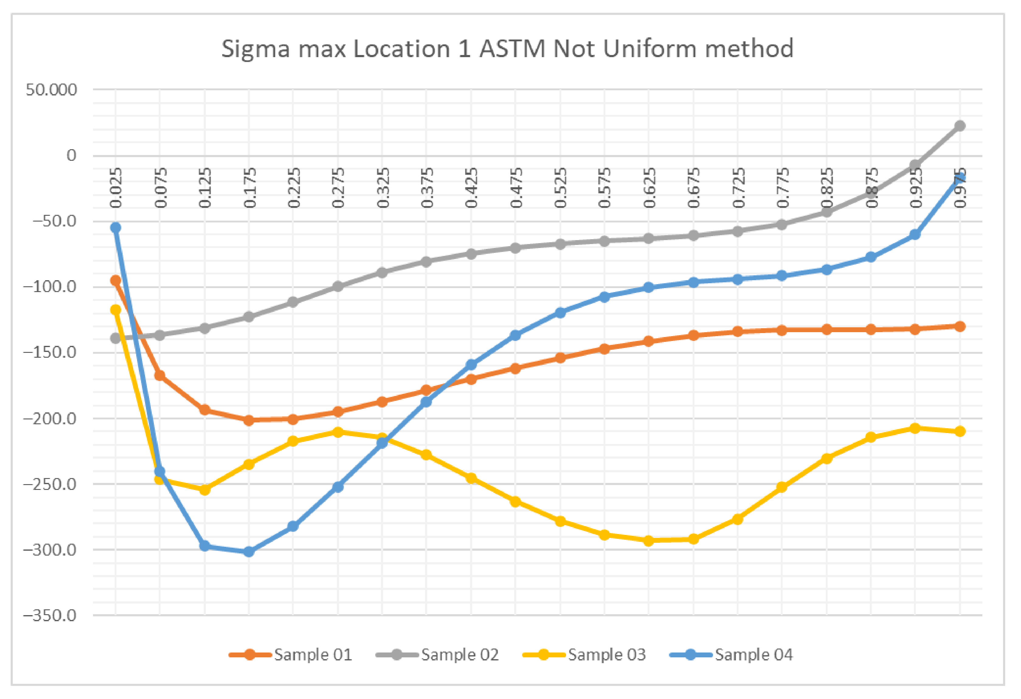
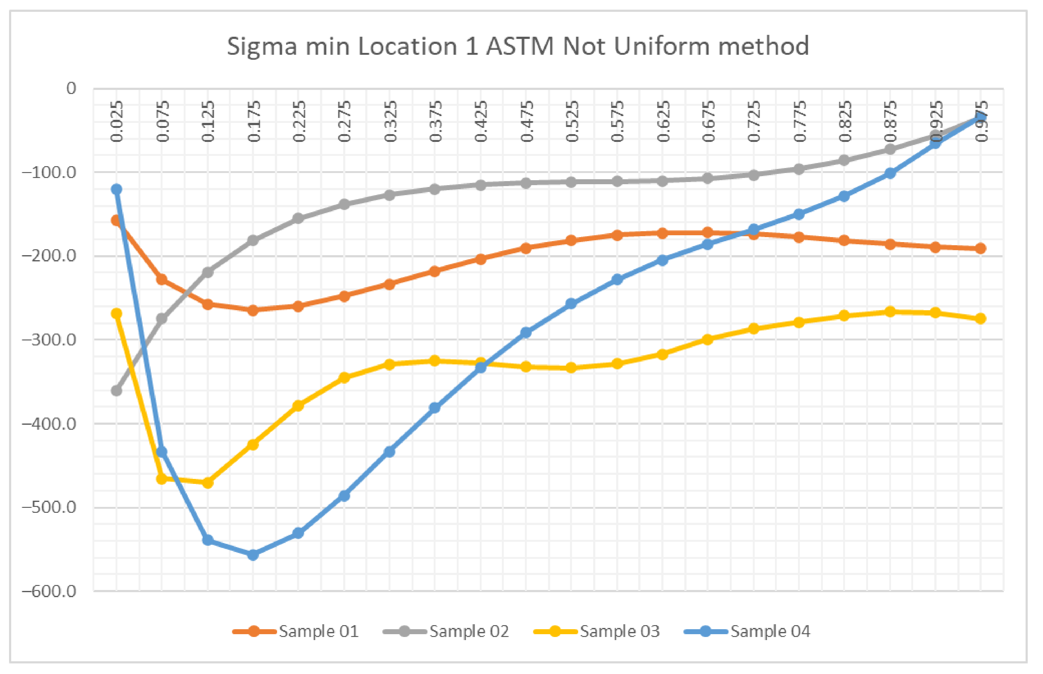
3. Results and Discussion

For experimental measurement of residual stresses, four samples were used, where two locations at equal distances from the edge of the cladding layer were selected on each (Figure 4). The hole drilling method was used to determine the residual stresses, where the released relative deformations in the vicinity of the drilled blind hole are registered by means of a strain gauge.
The depth of the blind hole is 2 mm, in accordance with ASTM E837. As already mentioned, the thickness of the cladding layers using different technologies varies. In the case of the analyzed samples, the thickness of the cladding layer is in the range from 1.1 mm to 4.5 mm. It follows that in some cases the blind hole interferes with the base material, which could to some extent affect the measured values of the released relative deformations on the surface of the cladding layer.
The ASTM not uniform method was chosen to compare the distribution of major residual stresses (Sigma max and Sigma min) in depth. A graphical interpretation of the results is shown in Figure 5, Figure 6, Figure 7 and Figure 8.
In Figure 5 and Figure 7, the Sigma max residual stress waveforms are measured on four samples. In Figure 6 and Figure 8 the residual stress of the Sigma min is shown.
Figure 5. The resulting values of residual stresses (Sigma max) for all four samples at the measuring Location 1.
Metals 12 00388 g005
Figure 6. The resulting values of residual stresses (Sigma min) for all four samples at the measuring Location 1.
Metals 12 00388 g006
Figure 7. The resulting values of residual stresses (Sigma max) for all four samples at the measuring Location 2.
Metals 12 00388 g007
Figure 8. The resulting values of residual stresses (Sigma min) for all four samples at the measuring Location 2.
Metals 12 00388 g008
As can be seen from Figure 5, Figure 6, Figure 7 and Figure 8, compressive values of residual stresses were measured at almost all depths. Mild values of tensile stresses were registered only for Sample 2 at a depth of about 1 mm.
Not only the nature of the stress course over the depth but also the slight difference between the assessed locations 1 and 2 on the same sample seem interesting.
Maximum values of Sigma max compressive stresses in both locations on Sample 04 were almost the same, approximately −300 MPa, but in location 1 it was 0.175 mm deep and in location 2, which was closer to the surface, it was 0.075 mm deep. As for the Sigma min stresses on Sample 04, they were registered at the same depth for location 1 resp. location 2, but the values were different—in location 1 almost −520 MPa and in location 2 almost −400 MPa. However, it can be stated that the residual stresses are under consideration as compressive at the depth, so they do not cause a reduction in the service life of the component. It should be noted that this is a sample with a thinner cladding layer.
Samples 01 and 03 show a similar character of residual stress levels with slight deviations and, of course, with different values. Regarding the overall assessment of the residual stresses in these samples, they are also compressive.
In the case of Sample 02, a different character was registered in terms of stress distribution over the depth. The most significant compressive values are just below the surface and increase gradually with increasing depth. In location 1 e.g., the Sigma max value at a depth of 0.025 mm is lower than for the samples 01, 03, and 04, but from the second step, i.e., from a depth of 0.075 mm, the Sigma max value is higher up to the assessed depth of 0.975 mm.
The difference in the residual stresses between location 1 and location 2 also seems interesting. Their character at location 2 on all four samples is almost identical for both Sigma max and Sigma min. From Figure 7 and Figure 8, a gradual increase in the values of the main residual stresses is evident from a depth of approximately 0.5 mm. On the contrary, for example, on Sample 01 at location 1, the Sigma max and Sigma min values were almost unchanged (constant) from a depth of approximately 0.5 mm.
Analysis of the results can be further divided into two parts. Samples 01 and 02 are included in the first group, where a thicker layer has been formed. Sample 01 had a thickness of 4.3 mm and was formed using a disk laser technique. Sample 02 had a thickness of layer 4.5 mm and was formed by CMT.
During the entire analyzed depth of Sample 01 (0–1 mm), only compressive residual stresses have been reported in both measured locations (Location 1 and 2). The overall method of renovation used on Sample 01 can be considered appropriate because there was no tensile residual stress at a depth of 1 mm.
For Sample 02, in location 1 from the depth of 0.8 mm, the tensile residual stress has been recorded (up to this depth, only compressive residual stress was recorded). In depth of about 1 mm, residual stress reached a value of about 20 MPa, which is still low. With increasing depth, residual stress is likely to have further growing character. Therefore, it seems the use of a renovation method that was deployed for Sample 02 is less suitable compared to the method used in Sample 01.
The second group consists of samples 03 and 04. The cladding layer on Sample 03 was realized by MIG Pulse and reached a thickness of 1.1 mm. The cladding layer at Sample 04 was conducted using TOPTIG with a total thickness of 1.8 mm. Although drilling was performed in the depth of 2 mm in these samples, the evaluation interval of residual stress was 0–1 mm.
Only compressive residual stresses were recorded in both measured locations at Sample 03. Although at measurement Location 1, the maximum of Sigma max value was recorded just below the surface of the cladding layer (−117 MPa), other value ranges were from −300 to −200 MPa., which represents a favorable state of residual stress. At measurement Location 2, the residual stress levels were not as low, and at a depth of 1 mm, the recorded value of the Sigma max was approximately −10 Mpa, which still represents compressive stress.
For Sample 04, the residual stress values between locations 1 and 2 show a similar character. The fundamental difference is that in location 1, the initial residual stress value just below the surface of the cladding layer reaches the value of −60 MPa, but in Location 2, it is −300 MPa. Subsequently, the Sigma max value did slightly drop. From this point, the residual stresses have only a growing character. At a depth of 1 mm, the value of approximately −10 MPa was detected, so it is still compressive stress. The lowest Sigma max −300 MPa value was recorded, which is approximately the same as at the measurement location. Subsequently, the residual stress values were rising and at a depth of 1 mm reached a value of −20 MPa, which is again similar to the value specified at measurement point 2.
The results obtained are more favorable in Sample 04 compared to Sample 03 because lower residual stress was recorded in both sample measurement locations and all residual stress values have only a compressive character.

4. Conclusions

The aim was to assess four different progressive cladding techniques to residual stress levels. The base material was the same in all cases and had the same thickness. After cladding, samples were heat treated and machined to the required surface quality. Thus, four samples were formed, which had different thicknesses of the cladding layer. The robotized cladding methods resulted in very good quality layers. The residual stresses were then determined using the hole drilling method.
In samples 01, 03, and 04, compressive residual stresses were recorded up to a depth of 1 mm, which represents sufficient resistance to the formation and spread of cracks in renovated molds. Only Sample 02 showed tensile residual stresses near a depth of 1 mm.
The residual stress measurements show that the disk laser technique used for Sample 01 is more suitable in terms of residual stresses when forming a thicker cladding layer. However, if it is required to create a thinner cladding layer, the TOPTIG technique used in Sample 04 is more suitable with a lower value of residual stresses.
It should be noted that the values of the residual stresses before and after the processing of the cladding layer by machining were not compared. Nevertheless, the results obtained can be considered relevant, given that the values of the residual stress must be superimposed on the operating load during operation. In this case, the residual stress takes into account these real technological processes of material processing.
Presented results can be considered as another tool in the selection of a suitable method of creating a cladding layer, where, among other things, factors such as achieved hardness, time of financial implementation, and costs, etc. are assessed. In the next stage, metallurgical processes in the application of double and multilayer cladding layers will be analyzed, as the number of layers depends on the extent of damage to the molds and the required thickness, which must be supplemented by cladding.
Research is also directed to minimize heat treatment times and to verify the opportunities of interlayers with higher resistance to the formation and crack spread in materials. In this research, the possibilities of minimizing residual stress in renovated molds using, e.g., vibrating processing of cladding on molds, is outlined. Precisely for this purpose, it is advisable to apply a cladding method, minimizing the metallurgical changes in cladding surfaces and thus minimizing residual stress in the clads.

Author Contributions

Conceptualization, J.B. (Janette Brezinová), M.P., and P.Š.; methodology, J.B. (Janette Brezinová), M.P., and P.Š.; validation, P.Š. and M.P.; formal analysis, P.Š. and M.P.; investigation, P.Š., M.P. and J.B. (Jakub Brezina); resources, P.Š., J.B. (Janette Brezinová), and J.V.; draft preparation, P.Š. and J.V.; writing—review and editing, P.Š. and J.V.; visualization, P.Š. and J.V.; project administration, J.B. (Janette Brezinová); funding acquisition, J.B. (Jakub Brezina). All authors have read and agreed to the published version of the manuscript.

Funding

This contribution is the result of the project implementation: Innovative approaches of the restoration of functional surfaces by laser weld overlaying (APVV-20-0303), supported by the Slovak Research and Development Agency and supported by the Ministry of Education of Slovakia Foundation under grant projects VEGA No. 1/0497/20, KEGA No. 044TUKE-4/2021 and APVV-15-0435.

Institutional Review Board Statement

Not applicable.

Informed Consent Statement

Not applicable.

Data Availability Statement

Not applicable.

Conflicts of Interest

The authors declare no conflict of interest.

References

  1. Park, S.; Ahn, C.; Lee, E. Evaluation of Corrosion Behavior on Crept AlSi10MnMg (AA365) Alloy Produced by High-Pressure Die-Casting (HPDC). Appl. Sci. 2021, 11, 6227. [Google Scholar] [CrossRef]
  2. Popov, V.V.; Pismenny, A.; Larianovsky, N.; Lapteva, A.; Safranchik, D. Corrosion Resistance of Al–CNT Metal Matrix Composites. Materials 2021, 14, 3530. [Google Scholar] [CrossRef] [PubMed]
  3. Nourian-Avval, A.; Fatemi, A. Characterization and Analysis of Porosities in High Pressure Die Cast Aluminum by Using Metallography, X-Ray Radiography, and Micro-Computed Tomography. Materials 2020, 13, 3068. [Google Scholar] [CrossRef] [PubMed]
  4. Zheng, T.; Hu, Y.; Meng, W.; Tang, A.; Pan, F. Corrosion and Residual Strength Analysis of High Pressure Die Casting AM Series Mg Alloys. Materials 2019, 12, 2624. [Google Scholar] [CrossRef] [Green Version]
  5. Song, X.; Tao, Y.; Ruidong, G.; Xuedong, L.; Lixuan, Z. Crack analysis of Cr-Mo-V-Si medium-carbon alloy steel in casting die. Eng. Fail. Anal. 2021, 120, 105083. [Google Scholar] [CrossRef]
  6. Salem, M.; Roux, S.; Dour, G.; Lamesle, P.; Choquet, K.; Rézaï-Aria, F. Effect of aluminizing and oxidation on the thermal fatigue damage of hot work tool steels for high pressure die casting applications. Int. J. Fatigue 2019, 119, 126–138. [Google Scholar] [CrossRef] [Green Version]
  7. Viňáš, J.; Brezinová, J.; Guzanová, A. Tribological properties of selected ceramic coatings. J. Adhes. Sci. Technol. 2013, 27, 196–207. [Google Scholar] [CrossRef]
  8. Ding, R.; Yang, H.; Hu, G.; Mo, J.; Chu, M.; Paddea, S.; Zhang, S.; Zhang, P.; Liu, Z.; Wei, J. Failure analysis of H13 steel die for high pressure die casting Al alloy. Eng. Fail. Anal. 2021, 124, 105330. [Google Scholar] [CrossRef]
  9. Brezinová, J.; Džupon, M.; Vojtko, M.; Viňáš, J.; Milkovič, O.; Brezina, J.; Guzanová, A.; Draganovská, D. Application of Cold Metal Transfer Welding for High Pressure Die Casting Mold Restoration. Metals 2019, 9, 1232. [Google Scholar] [CrossRef] [Green Version]
  10. Cornacchia, G.; Cecchel, S. Study and Characterization of EN AW 6181/6082-T6 and EN AC 42100-T6 Aluminum Alloy Welding of Structural Applications: Metal Inert Gas (MIG), Cold Metal Transfer (CMT), and Fiber Laser-MIG Hybrid Comparison. Metals 2020, 10, 441. [Google Scholar] [CrossRef] [Green Version]
  11. He, X.; Kong, D.; Song, R. Microstructures and Properties of Laser Cladding Al-TiC-CeO2 Composite Coatings. Materials 2018, 11, 198. [Google Scholar] [CrossRef] [Green Version]
  12. Viňáš, J.; Brezinová, J.; Guzanová, A.; Balog, P. Evaluation of the quality of cladding deposited on continuous steel casting rolls. Int. J. Mater. Res. 2013, 104, 183–191. [Google Scholar] [CrossRef]
  13. Trebuňa, F.; Šimčák, F.; Bocko, J.; Šarga, P.; Trebuňa, P.; Pástor, M.; Mihok, J. Quantification of residual stresses in the weld by the hole-drilling method. Metalurgija 2008, 47, 133–137. [Google Scholar]
  14. Trebuňa, F.; Šimčák, F.; Buršák, M.; Bocko, J.; Šarga, P.; Pástor, M.; Trebuňa, P. Quantification of residual stresses in hot rolled steel sheets by the hole drilling method. Metalurgija 2007, 46, 41–46. [Google Scholar]
  15. Pástor, M.; Bocko, J.; Lengvarský, P.; Sivák, P.; Šarga, P. Experimental and Numerical Analysis of 60-Year-Old Sluice Gate Affected by Long-Term Operation. Materials 2020, 13, 5201. [Google Scholar] [CrossRef]
  16. Šarga, P.; Trebuňa, F. Modern trends in the field of measurement of residual stresses using hole-drilling method. Am. J. Mech. Eng. 2016, 4, 353–356. [Google Scholar] [CrossRef]
  17. Li, R.; Qiu, Y.; Zheng, Q.; Liu, B.; Chen, S.; Tian, Y. Finite Element Simulation of Temperature and Stress Field for Laser Cladded Nickel-Based Amorphous Composite Coatings. Coatings 2018, 8, 336. [Google Scholar] [CrossRef] [Green Version]
  18. Paul, S.; Thool, K.; Singh, R.; Samajdar, I.; Yan, W. Experimental Characterization of Clad Microstructure and its Correlation with Residual Stresses. Procedia Manuf. 2017, 10, 804–818. [Google Scholar] [CrossRef]
  19. Yao, F.; Fang, L. Thermal Stress Cycle Simulation in Laser Cladding Process of Ni-Based Coating on H13 Steel. Coatings 2021, 11, 203. [Google Scholar] [CrossRef]
  20. Ding, C.; Cui, X.; Jiao, J.; Zhu, P. Effects of Substrate Preheating Temperatures on the Microstructure, Properties, and Residual Stress of 12CrNi2 Prepared by Laser Cladding Deposition Technique. Materials 2018, 11, 2401. [Google Scholar] [CrossRef] [Green Version]
  21. Preedawiphat, P.; Mahayotsanun, N.; Sa-ngoen, K.; Noipitak, M.; Tuengsook, P.; Sucharitpwatskul, S.; Dohda, K. Mechanical Investigations of ASTM A36 Welded Steels with Stainless Steel Cladding. Coatings 2020, 10, 844. [Google Scholar] [CrossRef]
  22. Karolczuk, A.; Kluger, K.; Derda, S.; Prażmowski, M.; Paul, H. Influence of Impact Velocity on the Residual Stress, Tensile Strength, and Structural Properties of an Explosively Welded Composite Plate. Materials 2020, 13, 2686. [Google Scholar] [CrossRef] [PubMed]
  23. Qin, M.; Cheng, G.; Li, Q.; Zhang, J. Evolution of Welding Residual Stresses within Cladding and Substrate during Electroslag Strip Cladding. Materials 2020, 13, 4126. [Google Scholar] [CrossRef] [PubMed]
  24. Singh, G.; Kalita, B.; Vishnu Narayanan, K.I.; Arora, U.K.; Mahapatra, M.M.; Jayaganthan, R. Finite Element Analysis and Experimental Evaluation of Residual Stress of Zr-4 alloys Processed through Swaging. Metals 2020, 10, 1281. [Google Scholar] [CrossRef]
  25. Bučkovice, W. JKZ. NR. 1.2344. Available online: https://www.jkz.cz/cs/produkty/nastrojove-oceli/pro-prace-za-tepla/w-nr-12344/ (accessed on 16 December 2021).
  26. Meusburger, 1.2343/1.2343 ESU Hot-Work Steel. Available online: https://www.meusburger.com/EN/US/material-grades/12343-12343-esr-hot-work-steel-die-making (accessed on 16 December 2021).
  27. Meusburger, 1.2344/1.2344 ESU Hot-Work Steel. Available online: https://www.meusburger.com/EN/US/material-grades/12344-12344-esr-hot-work-steel (accessed on 16 December 2021).
  28. Dutra, J.C.; Bonacorso, N.G.; Silva, R.; Carvalho, R.; Silva, F. Development of a flexible robotic welding system for weld overlay cladding of thermoelectrical plants’ boiler tube walls. Mechatronics 2014, 24, 416–425. [Google Scholar] [CrossRef]
  29. Siddiqui, A.; Dubey, A. Recent trends in laser cladding and surface alloying. Opt. Laser Technol. 2021, 134, 106619. [Google Scholar] [CrossRef]
  30. TruDisk 4002. Available online: https://www.trumpf.com/en_US/products/laser/disk-lasers/trudisk/ (accessed on 16 December 2021).
  31. Pickin, C.G.; Williams, S.W.; Lunt, M. Characterisation of the cold metal transfer (CMT) process and its application for low dilution cladding. J. Mater. Process. Technol. 2011, 211, 496–502. [Google Scholar] [CrossRef] [Green Version]
  32. Imoudu, N.E.; Ayele, Y.Z.; Barabadi, A. The characteristic of cold metal transfer (CMT) and its application for cladding. In Proceedings of the International Conference on Industrial Engineering and Engineering Management IEEM, Singapore, 10–13 December 2017; pp. 1883–1887. [Google Scholar] [CrossRef] [Green Version]
  33. The Open University, Science, Maths and Technology, Gas Shielded Arc Welding Processes (TIG/MIG/MAG). Available online: https://www.open.edu/openlearn/science-maths-technology/engineering-technology/manupedia/gas-shielded-arc-welding-processes-tig/mig/mag (accessed on 16 December 2021).
  34. Weman, K. 8—MIG/MAG welding. In Welding Processes Handbook, 2nd ed.; Woodhead Publishing, Elsevier: Amsterdam, The Netherlands, 2012; pp. 75–97. [Google Scholar] [CrossRef]
  35. Fronius TPS600i. Available online: https://www.fronius.com/en/welding-technology/products/manual-welding/migmag/tpsi/tpsi/tps-600i (accessed on 16 December 2021).
  36. Weman, K. 6—TIG welding. In Welding Processes Handbook, 2nd ed.; Woodhead Publishing, Elsevier: Amsterdam, The Netherlands, 2012; pp. 63–69. [Google Scholar] [CrossRef]
  37. Lincoln Electric, Toptig. Available online: https://www.lincolnelectric.com/en-gb/automation/Pages/welding-processes-toptig.aspx (accessed on 16 December 2021).
  38. ASTM E 837-13a. Standard Test Method for Determining Residual Stresses by the Hole-Drilling Strain-Gage Method; ASTM International: New York, NY, USA, 2001.
  39. SINT Technology, Residual Stress. Available online: https://sint-technology.com/residual-stress/ (accessed on 16 December 2021).
Figure 1. Fractured surface of casting mold.
Metals 12 00388 g001
Figure 2. Degraded surface of high pressure die casting mold.
Metals 12 00388 g002
Figure 3. Samples after heat treatment and subsequent machining.
Metals 12 00388 g003
Figure 4. Sample 03 after drilling measuring locations 1 and 2.
Metals 12 00388 g004
Table 1. Chemical composition of the base material X38CrMoV5-1 (wt.%).
CMnSiPSCrFeNiMoVCuFe
0.3840.3720.9150.0020.0094.67091.5800.1961.2700.5000.072Bal.
Table 2. Mechanical properties of the base material X38CrMoV5-1 by manufacturer.
Yield Strength
(MPa)
Tensile Strength
(MPa)
Elongation A5
(%)
Hardness
HRC
142016801250
Table 3. Chemical composition of the X38CrMoV5-1 additive material (in wt.%). Fe bal.
CCrSiMoMnV
0.355.000.202.300.500.60
Table 4. Mechanical properties of the cladding wire Diavar by manufacturer.
Yield Strength
(MPa)
Tensile Strength
(MPa)
Elongation A5
(%)
Hardness
HRC
105513081248
Publisher’s Note: MDPI stays neutral with regard to jurisdictional claims in published maps and institutional affiliations.

