Article

Kinetics of Carbon Partitioning of Q&P Steel: Considering the Morphology of Retained Austenite

1
The State Key Laboratory of Refractories and Metallurgy, Wuhan University of Science and Technology, Wuhan 430081, China
2
School of Materials and Metallurgy, Wuhan University of Science and Technology, Wuhan 430081, China
3
School of Mechanical Engineering, Dalian University of Technology, Dalian 116024, China
*
Author to whom correspondence should be addressed.
Metals 2022, 12(2), 344; https://doi.org/10.3390/met12020344
Submission received: 14 January 2022 / Revised: 11 February 2022 / Accepted: 14 February 2022 / Published: 16 February 2022

Abstract

:
The diffusion of carbon atoms from martensite to retained austenite (RA) is controlled by the carbon partitioning kinetics when the quenching and partitioning (Q&P) process is conducted. The RA is divided into film-like and blocky ones in morphology. This research aims to study the influence of the morphology of RA on the kinetics of carbon partitioning mainly by developing a numerical simulation. A one-step Q&P process was modeled at the partitioning temperature of 330–292 °C, with a partitioning time ranging from 10 6 to 5   ×   10 3 s. The finite element method was employed to solve the carbon diffusion equation. A thermomechanical simulator Gleeble-3500 was used to conduct the corresponding Q&P heat treatment, and the RA was examined by X-ray diffraction. The results show that the film-like RA will be enriched in carbon within a short time at first, followed by a decrease in carbon concentration due to the massive absorption of carbon by blocky RA, leading the stable film-like RA to become unstable again. The end of the kinetics of carbon partitioning was the concentration determined by the constrained carbon equilibrium (CCE) model, provided that the CCE condition was employed in this study. It took quite a long time (thousands of seconds) to complete the carbon partitioning globally, which was influenced by the partitioning temperature.

1. Introduction

Quenching and partitioning (Q&P) is a promising technique to produce steels with excellent mechanical performance [1,2]. The Q&P steel is first quenched to a temperature below the martensite start ( M s ) temperature to obtain a desired volume fraction of martensite. Subsequently, the steel is held at or above this temperature for carbon atoms diffusing from the martensite to untransformed austenite [3]. The chemical potential gradient of carbon provides the driving force for the carbon atoms to transport. The untransformed carbon-enriched austenite will remain stable after the secondary quenching to room temperature [4]. The retained austenite (RA) will transform to martensite when subject to deformation [5], enhancing the ductility and toughness of the Q&P steel [6,7]. Obtaining substantial stable RA at room temperature is essential to achieve high strength without compromising the toughness [8,9,10].
Ideally, it is believed that there is an optimum quenching temperature at which a specific volume of martensite provides just sufficient carbon atoms to make the untransformed austenite carbon-enriched and remain stable without fresh martensite formation during final quenching to room temperature [1]. Under the constrained carbon equilibrium (CCE) condition, a model proposed by Speer et al. [4] can be used to predict the optimum quenching temperature and the corresponding carbon concentration in carbon-depleted martensite and carbon-enriched RA. However, this model is thermodynamic without considering the influence of the carbon partitioning kinetics on the stability of the untransformed austenite [11].
A few models [11,12,13,14,15] have been developed to simulate the carbon profiles along the half-width martensitic lath and film-like RA as a function of partitioning time at a given partitioning temperature with a specific austenite fraction. These one-dimensional models were usually developed for the assembly of lath martensite and film-like RA. When modeling, the width of the martensitic lath was assumed to be constant [11], and the width of film-like RA was determined according to the fraction of untransformed austenite [11,12,14,16]. However, according to the experimental research, there are film-like and block-like RA in morphology with different stability [17,18,19,20,21,22,23]. The width of the martensitic lath is related to the effective carbon concentration [24]. Moreover, the film-like RA is almost observed between the laths with the width ranging from 50 to 200 nm [25,26]. Thus, it is not rigorous to set the width of retained austenite according to the austenite fraction.
In this research, a model that incorporated the kinetics of carbon partitioning was developed to study the influence of morphology (blocky and film-like) of RA on the final stable RA fraction. A corresponding experiment was conducted to verify the rationality and validity of the model.

2. Materials and Methods

2.1. Materials and Procedure

The material used in this study was a Q&P steel with the chemical composition of Fe-0.193C-1.702Si-1.953Mn (wt %). The samples with dimensions of 90 × 25 × 1.8 mm were machined from a hot-rolled steel strip produced by Wuhan Iron and Steel Co., Ltd. CSP plant (Wuhan, China). The dominant microstructure of the given steel was bainite. A thermomechanical simulator Gleeble-3500 (DSI, New York, USA) was used to control the heating condition. Resistance heating and N2 gas were used to heat and cool the samples to the desired temperature. A highly vacuumed test chamber suppressed the surface oxidation of samples.
In order to obtain the martensite transformation kinetics as a function of quenching temperature, the quenching experiment was first carried out. A sample was heated to 900 °C with a heating rate of 10 °C / s , holding for 5 min to achieve a fully austenitic structure. Then, the sample was quenched to room temperature with a cooling rate of 50 °C / s . Thermal expansion curves were recorded. The lever rule was used to obtain the volume fraction of transformed martensite when cooled to a given temperature.
Other samples were also heated to 900 °C with a heating rate of 10 °C / s , holding for 5 min for austenitization. Then, the samples were quenched to 330, 310, and 292 °C at a cooling rate of 50 °C / s , holding for 1, 2, and 5 min for carbon partitioning. Subsequently, the samples were quenched to room temperature at a cooling rate greater than 30 °C / s .
Samples subjected to quenching and partitioning heat treatment were carefully ground to reduce the influence of surface decarburization. Electrolytic polishing rather than mechanical polishing was performed to prevent the unexpected martensitic transformation from RA. The volume fraction of RA was measured using the X-ray diffraction method [27,28] with Cu-Kα radiation at 40 kV and 50 mA. Patterns were recorded at the rate of 5°/min over the range (2 θ ) 40–100° with a step size of 0.02 .

2.2. Kinetics of Carbon Partitioning

2.2.1. Governing Equation

Martensitic transformation occurs when fully austenitized steel is quenched to the temperature below M s . The microstructure predominantly consists of primary martensite and untransformed austenite when the target quenching temperature is between M s and M f . The chemical potential of carbon in the primary martensite is higher than that in the untransformed austenite. This difference in chemical potential results in a carbon diffusional flux from primary martensite to untransformed austenite. According to the multi-component diffusion theory, the flux of carbon is driven by the chemical potential gradient, which can be described as [12,29]:
J c i = M c i C c i μ c i
where M c is the mobility coefficient of carbon, superscript i denotes the diffusional matrix, i.e., martensite or austenite, C is the mole fraction of carbon, μ c is the chemical potential gradient of carbon. The diffusion coefficient as a function of the atomic mobility obeys the Nernst–Einstein equation, which can simply be expressed as:
D c i = 1 + d ln f c i d ln C c i M c i R T M c i R T
where R is the gas constant, T is the absolute temperature, and f c is the activity coefficient of carbon, which is approximately equal to 1, considering the dilute alloy condition. Substituting Equation (2) into Equation (1) yields Equation (3):
J c i = D c i C c i R T μ c i .
From the conservation of carbon atoms:
C c i t = J c i .
Substituting Equation (3) into Equation (4) gives the final diffusional governing equation:
C c i t = x D c i C c i R T μ c i x
where C c i , D c i , and μ c i are the mole fraction, diffusion coefficient, and chemical potential of carbon. It is assumed that a one-dimensional diffusion is involved and the X-axis direction is set to be aligned with the carbon diffusion gradient direction.

2.2.2. Initial and Boundary Condition

An assumption is made that the carbon atoms are uniformly distributed in the steel at the beginning of the partitioning. The carbon concentration in primary martensite and untransformed austenite is the same: equal to the nominal composition. A half-length of the prior austenite, 5000 nm, was selected as the spatial range. A Neumann boundary condition was applied:
J ( x s , t ) = J ( x e , t ) = 0
where x s and x e denote the start and endpoint of the diffusion range.

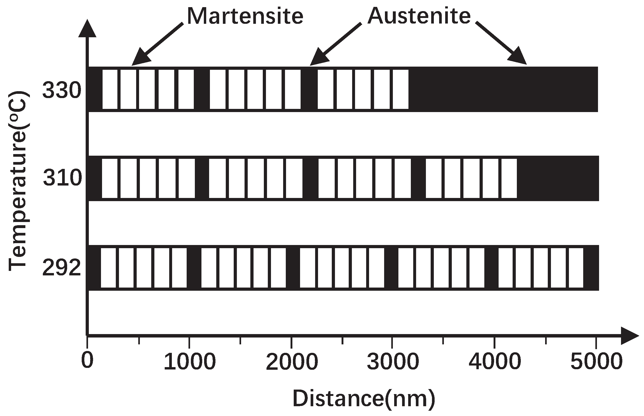
2.2.3. Modeling Conditions

The finite element method was employed to discretize the simulation domain. Along the diffusion range, 5001 equally spaced nodes were introduced, which means d x = 1 nm. The diffusion coefficient of carbon in martensite is much larger than in austenite, making it difficult to converge when solving the diffusion equation. Therefore, an interface width was set to equal to 10 nm, within which a smoothed step function was introduced to facilitate that the diffusion equation can be solved successfully. During the simulation, the modeling time varied from 10 6 to 5 × 10 3 s, and the time-step, d t , was taken as 10 6 s to ensure that the results were accurate and reliable. The prerequisite for solving the diffusion equation is to determine the evolving parameters. The chemical potential and diffusion coefficient as functions of chemical composition are listed in Table 1.
The steel quenched to the temperature between M s and M f has the microstructures comprised of primary martensite and untransformed austenite. After partitioning, the untransformed austenite becomes carbon-enriched and remains stable when quenched to room temperature. These RAs are roughly classified into film-like and blocky types, and the former is predominantly located between the martensitic laths [20,32]. A number of martensitic laths, film-like austenite, and a blocky austenite were reasonably distributed along the simulation domain, as shown in Figure 1 schematically.
According to the previous research, the lath width is heavily dependent on the carbon concentration of the prior austenite before quenching. It can be mathematically expressed as [24]:
d M l a t h = d C o t t r e l l C c γ 2 3
where d C o t t r e l l is the radius of a Cottrell atmosphere, which was taken as 7 nm [33] in this work. Substituting the nominal carbon concentration in the prior austenite gave d M l a t h = 164 nm. Taking into account the fluctuation of the carbon content in practice, it is reasonable to set the martensitic lath width between 150 and 200 nm in modeling process.
In this study, a parameter α was proposed to depict the probability of film-like RA between martensitic laths. The quantitative relationship of the martensitic lath, film-like, and blocky austenite can be expressed by the following equations:
m d M l a t h + n d A f i l m + d A b l o c k = d
m d M l a t h d = v M
n m = α
where d is the total width, d M l a t h is the width of martensitic lath, and d A f i l m and d A b l o c k are the width of film-like and blocky RA. d A f i l m is approximately 100 to 120 nm, according to the experimental observation reported in the existing literature. v M is the volume fraction of the primary martensite after the first quenching, m and n are the number of martensitic lath and film-like RA, respectively. The detailed information is shown in Table 2.
Constrained carbon equilibrium (CCE) conditions proposed by Speer et al. [1,4] were employed in this study. Thus, it was assumed that no cementite formation occurred, the interface between the austenite and martensite is stationary, and the carbon diffusion is completed when the chemical potential of carbon in martensite is equal to that in austenite.

3. Results and Discussion

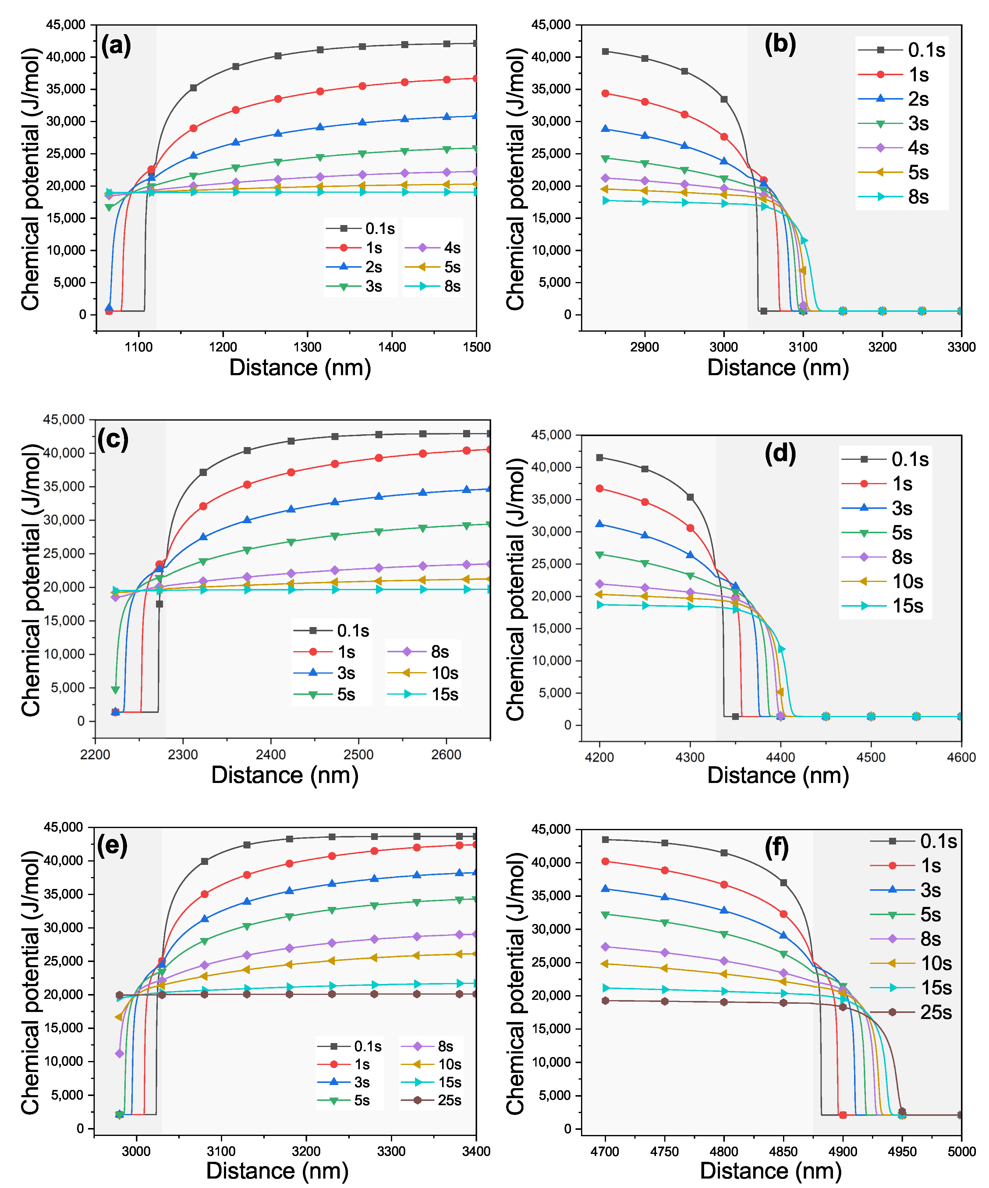
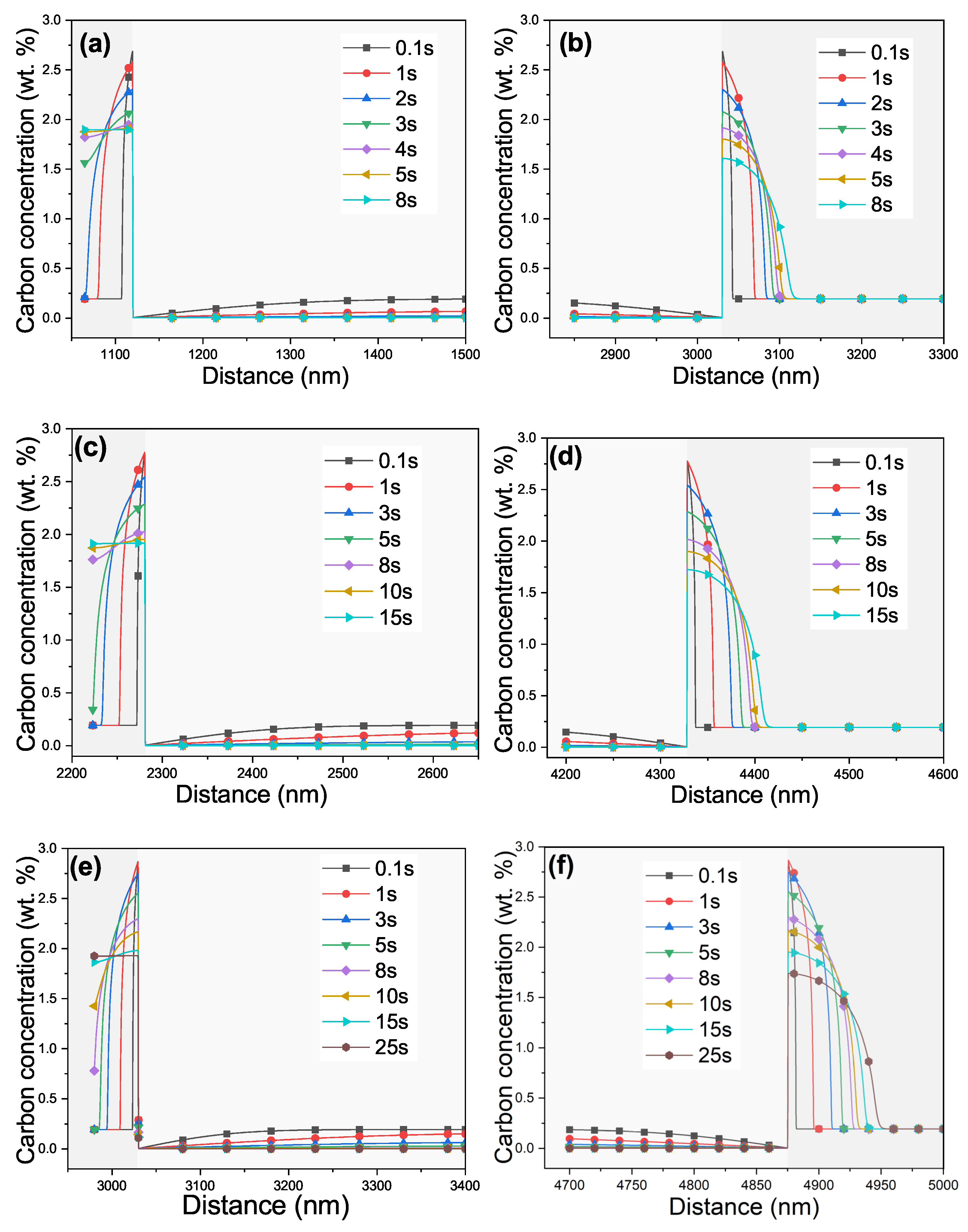
3.1. Evolution of the Carbon Chemical Potential and Concentration

The difference in the chemical potential of carbon in the primary martensite and untransformed austenite provides the driving force for the carbon atoms to diffuse from the martensite to the austenite. Figure 2 shows the evolution of the chemical potential profiles of carbon as a function of partitioning time at different quenching temperatures. It can be seen that the chemical potential of carbon in martensite is much larger than that in austenite at the initial stage. As the partitioning time increases, the chemical potential of carbon in martensite is gradually decreasing, while that in austenite is increasing. When the chemical potential of carbon in austenite and martensite was identical, the partitioning process was finished. This time consumed was greatly affected by partitioning temperature. As for the film-like austenite, the time to complete the partitioning locally at 330, 310, and 292 °C was 8, 15, and 25 s, respectively, as shown in Figure 2a,c,e. These results, in magnitude, were consistent with values calculated in previous work with similar chemical composition and Q&P treatment [12,14].
However, as for the blocky austenite, the partitioning was far from completion within the same time. This is mainly attributed to the larger domain of blocky austenite, which requires a longer partitioning time and more carbon atoms for equilibrium. Blocky austenite with lower carbon concentration (compared with the film-like RA) was also observed frequently in previous experimental research [20,26].
Figure 3 shows the corresponding carbon concentration profiles on both sides of the martensite/austenite interface. As can be seen, the carbon concentration profile evolution trends are consistent with those of the chemical potential in Figure 2. It should be noted that there was a peak of carbon concentration on the austenite side at the martensite/austenite interface. Within a short period of time after the partitioning started, this peak value would reach a maximum. When the partitioning time increased, this peak value decreased. The reason for the existence of a sharp peak was that the diffusion coefficient of carbon in austenite is four orders of magnitude smaller than that in martensite. The carbon atoms cannot diffuse from the vicinity of the interface into the inside of the austenite in time. Therefore, it can be reasonably deduced that it was the diffusion of carbon in austenite that controlled the partitioning process rather than carbon diffusion in martensite [14]. The diffusion coefficient of carbon in austenite is affected by the temperature. Hence, when partitioning for the same time (0.1 s, for example), the peak value increased with the partitioning temperature. Similar results [12,14] were found in previous literature.
The rapid carbon enrichment of film-like RA was attributed to its large specific surface area [20]. Within a short time of partitioning, the carbon concentration in film-like austenite was increasing as high as 1.8 wt %, completing partitioning locally and temporarily. Generally speaking, this value was in good agreement with the previous modeling and experimental work [12,14,28,34,35], taking into account the differences in modeling and Q&P heat treatment conditions. In previous modeling [12,14], the width of the RA was set based on the fraction of untransformed austenite without considering the existence of the blocky austenite, yielding a higher width ratio of austenite to martensite and a lower carbon concentration in equilibrium locally. In this study, the CCE criteria were employed, which indicated that reactions (such as carbide precipitation, bainite formation) competing with carbon partitioning were ignored, resulting in a slightly higher carbon concentration in austenite than that observed in the experiment. It should be noted that some film-like RAs enriched in high carbon concentration were observed nevertheless [20,34]. By contrast, large blocky RA with high carbon concentration was observed scarcely, for carbon enrichment is an essential prerequisite for the stability of RA.

3.2. Volume Fraction of Retained Austenite

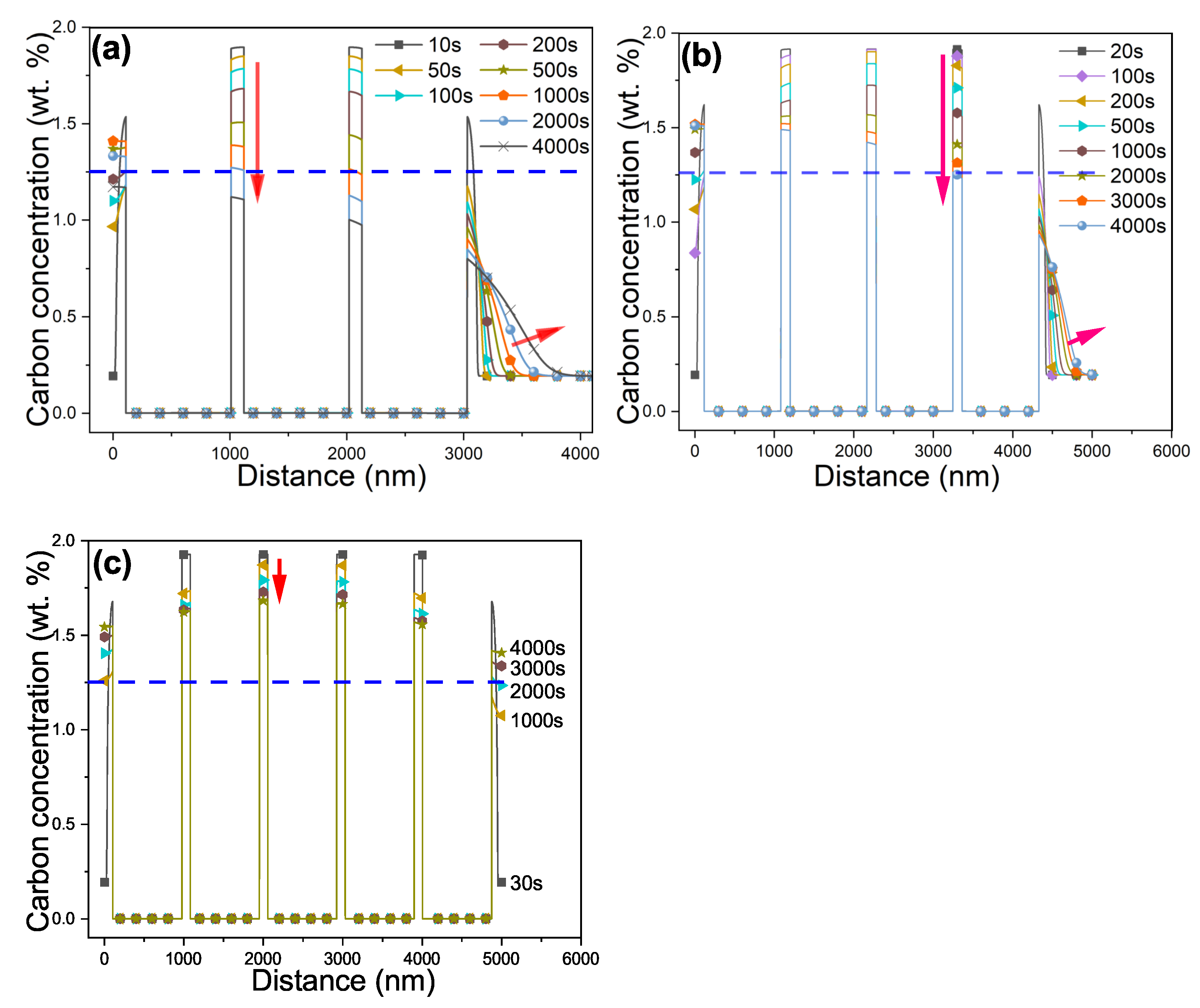
3.2.1. Bulk Carbon Concentration Distribution

According to the experimental results of martensitic transformation kinetics, the M s and M f temperatures of the Q&P steel were 262 and 236 °C respectively. When it was quenched to 330, 310, and 292 °C, 54, 77, and 87% martensite was formed, respectively. Based on this, the corresponding fraction of austenite exhibiting as film-like and blocky was modeled. Figure 4 gives the bulk carbon concentration distribution profiles in the martensite and austenite when partitioning up to 4 × 10 3 s at different partitioning temperatures. According to the results of simulated carbon concentration distribution in the vicinity of the film-like austenite/martensite interface, it is known that the partitioning of the carbon was completed in 8–25 s, locally. As the partitioning time prolonged, the carbon concentration in film-like austenite declined gradually. Meanwhile, the carbon concentration in blocky austenite increased. The red arrows in Figure 4 highlight the trends of the carbon concentrations profiles.
The chemical potential gradient of carbon provides the driving force for carbon atoms diffusion. The chemical potential of carbon in the austenite or martensite is carbon concentration dependent. The lower carbon concentration in blocky austenite, owing to the large volume fraction that needed a large number of carbon atoms to achieve chemical potential balance, resulted in a sub-domain with lower chemical potential. Consequently, a long-range diffusion of carbon atoms from martensite and film-like austenite to blocky austenite occurred. As a result, the carbon concentration in the film-like austenite may continue to decrease to or below a critical value above which the austenite could remain stable after being quenched to room temperature. The martensite start ( M s ) temperature can be expressed by the following expression [36]:
M s = 764.2 302.6 w C 30.6 w Mn 16.6 w Ni 8.9 w Cr + 2.4 w Mo 11.3 w Cu + 8.58 w Co + 7.4 w W 14.5 w Si
where w is the chemical composition in weight percent, and M s is in Kelvin. As the carbon concentration increases, the M s temperature decreases. In order to make the retained austenite remain stable at room temperature, the M s temperature of the retained austenite has to be below the room temperature (Tr). Substituting M s in Equation (11) with Tr:
T r = 764.2 302.6 w C 30.6 w Mn 16.6 w Ni 8.9 w Cr + 2.4 w Mo 11.3 w Cu + 8.58 w Co + 7.4 w W 14.5 w Si .
Then, the critical carbon concentration that makes the retained austenite remain stable at room temperature can be derived:
w C = 1 302.6 ( 764.2 30.6 w Mn 16.6 w Ni 8.9 w Cr + 2.4 w Mo 11.3 w Cu + 8.58 w Co + 7.4 w W 14.5 w Si T r ) .

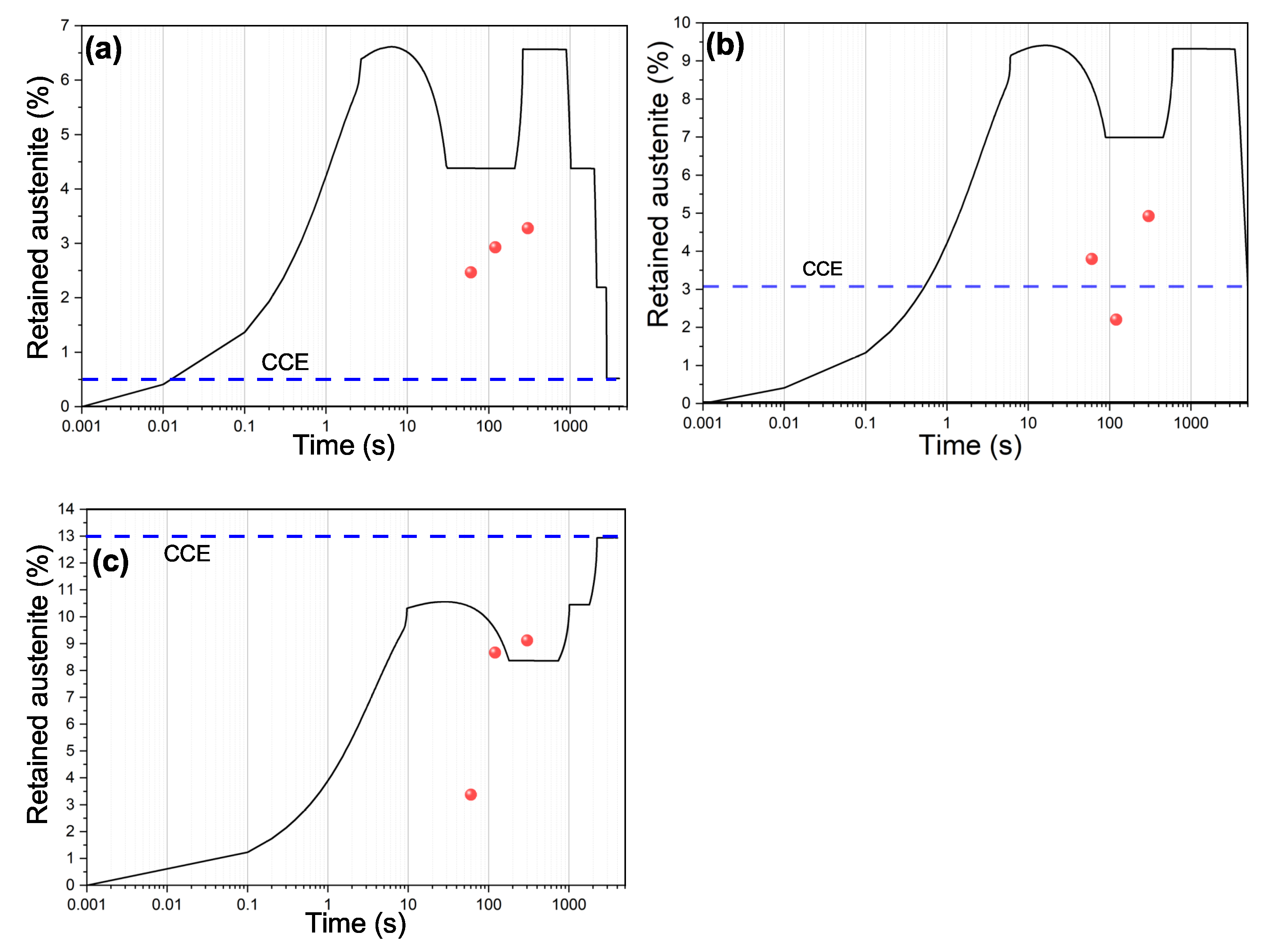
3.2.2. Retained Austenite

The stability of austenite at room temperature after the second quenching depends on whether the carbon concentration in austenite is higher than the critical value. The film-like austenite is carbon-enriched within a few seconds, as shown in Figure 3. However, due to the influence of blocky austenite, the carbon-enriched film-like austenite may become diminished in carbon, making it unstable at room temperature.
The evolution of the fraction of RA with partitioning time can be obtained by measuring the domain where the carbon concentration exceeds the critical value. The simulated results are shown in Figure 5. As can be seen, the fraction of RA increases with partitioning time to a peak value, which is followed by some fluctuations. The former continuous increase in the fraction of RA was due to the rapid carbon enrichment of film-like austenite. The fluctuations were attributed to the carbon diffusion from carbon-enriched film-like austenite and martensite to the blocky austenite with relatively low carbon concentration.
In the previous experimental research, it was often observed that the volume fraction of RA first increased and then decreased with partitioning time, especially when the quenching temperature was relatively higher [11,37,38], i.e., above the optimum quenching temperature. It should be noted that some results exhibited a monotonous decrease without increasing part of the fraction of RA with partitioning time [38,39]. It is speculated that the trend may be due to the long partitioning time, time steps, or equipment precision. It is widely accepted that the decreasing volume fraction of RA with partitioning time is attributed to the carbide formation [37,40,41,42]. According to the result of this study, it can be reasonably believed that the massive absorption of carbon by blocky austenite was one of the contributing factors in decreasing the volume fraction of RA with partitioning time. When the quenching temperature was relatively lower, i.e., below the optimum quenching temperature, the fraction of RA was found to increase monotonously [38], which was consistent with the result of this study (Figure 5c). Within a sufficient partitioning time, the fraction of RA was consistent with results computed by using the CCE model [4], since the same assumptions were applied. The consistency of the results proved the reliability of the model.
Figure 6 gives the results of X-ray diffraction at different partitioning temperatures and time. According to the intensity of the diffraction of the austenite, the volume fraction of the RA at room temperature can be determined. The experimental result is also presented in Figure 5. As the partitioning time increased, the fraction of RA increased when partitioning at 330 and 292 °C, as shown in Figure 5a,c, which is similar to the trend of the primary stage of the simulated results. However, when partitioning at 310 °C, the fraction of RA did not increase monotonically, similar to the changing trends of the second-stage simulation results. As can be seen, the experimental value is smaller than the simulated results. The discrepancy is mainly due to the assumption that competing reactions, such as carbide formation, are suppressed by alloying elements [3,43,44]. This assumption overestimates the available carbon for partitioning to RA. The evolution of the amount of RA as a function of the partitioning temperature and time can serve as the indirect proof of the kinetics of carbon partitioning. More experimental work, especially the directly observation of carbon partitioning, is needed for deeper validation of the model in the future.
Last but not least, the parameter α proposed in this study is theoretically reasonable, but the statistical evidence is a bit insufficient. It affects the fluctuation of simulation results within a short partitioning time, not the overall trends. Although the parameter α works well in this study, additional investigations are needed for its physical and statistical significance.

4. Conclusions

The partitioning of carbon from martensite to untransformed austenite during the partitioning process was simulated by employing the finite element method with the governing equation based on the chemical potential of carbon in austenite and martensite. The simulation used the same assumptions as the classical CCE model. The influence of austenite morphology on the kinetic of carbon partitioning was investigated quantitatively. From the results presented in this study, the following conclusions can be drawn:
  • In the primary stage of the partitioning, the film-like austenite will be enriched in carbon within a short time, leading to an increasing fraction of retained austenite with partitioning time. However, in the second stage, due to the influence of low carbon blocky austenite, the carbon concentration in film-like austenite that had been enriched in carbon and stable will be reduced, resulting in a fluctuation in the fraction of stable retained austenite.
  • The carbon diffusion is driven by the chemical potential gradient. The carbon atoms diffuse not only from martensite to untransformed austenite but also from carbon-enriched film-like austenite through martensite to low-carbon blocky austenite by long-range diffusion.
  • The kinetics of carbon partitioning is controlled by the diffusion of carbon in austenite and is significantly affected by the partitioning temperature.
  • The end of the kinetics of carbon partitioning was the concentration determined by the CCE model, provided that the CCE condition was employed in this study. It took quite a long time to complete the carbon partitioning globally, which was influenced by the partitioning temperature.

Author Contributions

Conceptualization, Y.X.; methodology, Y.X. and F.C.; software, Y.X. and Z.L.; validation, Y.X. and S.B.; formal analysis, Y.X., F.C. and G.Y.; investigation, Y.X. and J.S.; resources, X.M.; data curation, Y.X., Z.L. and J.S.; writing—original draft preparation, Y.X. and F.C.; writing—review and editing, Y.X., G.Y. and S.B.; visualization, Y.X. and F.C.; supervision, G.Z.; project administration, G.Z.; funding acquisition, X.M. All authors have read and agreed to the published version of the manuscript.

Funding

This research was funded by NATIONAL KEY RESEARCH AND DEVELOPMENT PROGRAM OF CHINA grant number 2021YFB3702402.

Institutional Review Board Statement

Not applicable.

Informed Consent Statement

Not applicable.

Data Availability Statement

The data are available from the authors upon reasonable request.

Acknowledgments

Wuhan Iron and Steel Co., Ltd. is acknowledged for providing Q&P steels.

Conflicts of Interest

The authors declare no conflict of interest. The funders had no role in the design of the study; in the collection, analyses, or interpretation of data; in the writing of the manuscript, or in the decision to publish the results.

Abbreviations

The following abbreviations are used in this manuscript:
Q&PQuenching and Partitioning
RARetained Austenite
CCEConstrained Carbon Equilibrium
MsMartensite Start (temperature)
MfMartensite Finish (temperature)

References

  1. Edmonds, D.V.; He, K.; Rizzo, F.C.; De Cooman, B.C.; Matlock, D.K.; Speer, J.G. Quenching and partitioning martensite—A novel steel heat treatment. Mater. Sci. Eng. A 2006, 438–440, 25–34. [Google Scholar] [CrossRef]
  2. Wang, Z.; Huang, M.X. Optimising the strength-ductility-toughness combination in ultra-high strength quenching and partitioning steels by tailoring martensite matrix and retained austenite. Int. J. Plast. 2020, 134, 102851. [Google Scholar] [CrossRef]
  3. Speer, J.G.; De Moor, E.; Clarke, A.J. Critical Assessment 7: Quenching and partitioning. Mater. Sci. Technol. 2015, 31, 3–9. [Google Scholar] [CrossRef]
  4. Speer, J.; Matlock, D.K.; De Cooman, B.C.; Schroth, J.G. Carbon partitioning into austenite after martensite transformation. Acta Mater. 2003, 51, 2611–2622. [Google Scholar] [CrossRef]
  5. Soleimani, M.; Kalhor, A.; Mirzadeh, H. Transformation-induced plasticity (TRIP) in advanced steels: A review. Mater. Sci. Eng. A 2020, 795, 140023. [Google Scholar]
  6. Wu, R.; Li, W.; Zhou, S.; Zhong, Y.; Wang, L.; Jin, X. Effect of Retained Austenite on the Fracture Toughness of Quenching and Partitioning (Q&P)-Treated Sheet Steels. Metall. Mater. Trans. A 2014, 45, 1892–1902. [Google Scholar]
  7. Salehiyan, D.; Samei, J.; Amirkhiz, B.S.; Hector, L.G.; Wilkinson, D.S. Microstructural Evolution During Deformation of a QP980 Steel. Metall. Mater. Trans. A 2020, 51, 4524–4539. [Google Scholar] [CrossRef]
  8. Xie, Z.J.; Ren, Y.Q.; Zhou, W.H.; Yang, J.R.; Shang, C.J.; Misra, R.D.K. Stability of retained austenite in multi-phase microstructure during austempering and its effect on the ductility of a low carbon steel. Mater. Sci. Eng. A 2014, 603, 69–75. [Google Scholar] [CrossRef]
  9. Shen, Y.; Qiu, L.; Sun, X.; Zuo, L.; Liaw, P.K.; Raabe, D. Effects of retained austenite volume fraction, morphology, and carbon content on strength and ductility of nanostructured TRIP-assisted steels. Mater. Sci. Eng. A 2015, 636, 551–564. [Google Scholar] [CrossRef] [Green Version]
  10. Zhou, S.; Hu, F.; Zhou, W.; Cheng, L.; Hu, C.; Wu, K. Effect of retained austenite on impact toughness and fracture behavior of medium carbon submicron-structured bainitic steel. J. Mater. Res. Technol. 2021, 14, 1021–1034. [Google Scholar] [CrossRef]
  11. Clarke, A.J.; Speer, J.G.; Matlock, D.K.; Rizzo, F.C.; Edmonds, D.V.; Santofimia, M.J. Influence of carbon partitioning kinetics on final austenite fraction during quenching and partitioning. Scr. Mater. 2009, 61, 149–152. [Google Scholar] [CrossRef] [Green Version]
  12. Seo, E.J.; Cho, L.; De Cooman, B.C. Kinetics of the partitioning of carbon and substitutional alloying elements during quenching and partitioning (Q&P) processing of medium Mn steel. Acta Mater. 2016, 107, 354–365. [Google Scholar]
  13. Klein, T.; Lukas, M.; Galler, M.; Ressel, G. Assessment of the Predictive Capabilities of Commercial Simulation Software Packages for the Analysis of the C Redistribution during Q&P Processing; IOP Conference Series: Materials Science and Engineering; IOP Publishing: Bristol, UK, 2018; Volume 461, p. 012039. [Google Scholar]
  14. Gonzalez L, J.C.; Li, W.; Gong, Y.; Jin, X. A Finite-Element Approach for the Partitioning of Carbon in Q&P Steel. Metall. Mater. Trans. B 2019, 50, 1417–1427. [Google Scholar]
  15. Klein, T.; Lukas, M.; Sartory, B.; Galler, M.; Ressel, G. Redistribution of C in a Martensite/Austenite Assembly Resulting from Q&P Processing: Computational Modeling Supported by Experiments. Metall. Mater. Trans. A 2019, 50, 4006–4011. [Google Scholar]
  16. Santofimia, M.; Speer, J.; Clarke, A.; Zhao, L.; Sietsma, J. Influence of interface mobility on the evolution of austenite–martensite grain assemblies during annealing. Acta Mater. 2009, 57, 4548–4557. [Google Scholar] [CrossRef] [Green Version]
  17. Tirumalasetty, G.; Van Huis, M.; Kwakernaak, C.; Sietsma, J.; Sloof, W.; Zandbergen, H. Deformation-induced austenite grain rotation and transformation in TRIP-assisted steel. Acta Mater. 2012, 60, 1311–1321. [Google Scholar] [CrossRef] [Green Version]
  18. Xiong, X.; Chen, B.; Huang, M.; Wang, J.; Wang, L. The effect of morphology on the stability of retained austenite in a quenched and partitioned steel. Scr. Mater. 2013, 68, 321–324. [Google Scholar] [CrossRef]
  19. Gao, G.; Zhang, H.; Gui, X.; Luo, P.; Tan, Z.; Bai, B. Enhanced ductility and toughness in an ultrahigh-strength Mn–Si–Cr–C steel: The great potential of ultrafine filmy retained austenite. Acta Mater. 2014, 76, 425–433. [Google Scholar] [CrossRef]
  20. Park, H.S.; Han, J.C.; Lim, N.S.; Seol, J.B.; Park, C.G. Nano-scale observation on the transformation behavior and mechanical stability of individual retained austenite in CMnSiAl TRIP steels. Mater. Sci. Eng. A 2015, 627, 262–269. [Google Scholar] [CrossRef]
  21. Chen, J.; Lv, M.; Tang, S.; Liu, Z.; Wang, G. Correlation between mechanical properties and retained austenite characteristics in a low-carbon medium manganese alloyed steel plate. Mater. Charact. 2015, 106, 108–111. [Google Scholar] [CrossRef]
  22. De Knijf, D.; Föjer, C.; Kestens, L.A.I.; Petrov, R. Factors influencing the austenite stability during tensile testing of Quenching and Partitioning steel determined via in-situ Electron Backscatter Diffraction. Mater. Sci. Eng. A 2015, 638, 219–227. [Google Scholar] [CrossRef]
  23. He, B. On the Factors Governing Austenite Stability: Intrinsic versus Extrinsic. Materials 2020, 13, 3440. [Google Scholar] [CrossRef]
  24. Galindo-Nava, E.I.; Rivera-Díaz-del Castillo, P.E.J. A model for the microstructure behaviour and strength evolution in lath martensite. Acta Mater. 2015, 98, 81–93. [Google Scholar] [CrossRef] [Green Version]
  25. Sun, J.; Yu, H. Microstructure development and mechanical properties of quenching and partitioning (Q&P) steel and an incorporation of hot-dipping galvanization during Q&P process. Mater. Sci. Eng. A 2013, 586, 100–107. [Google Scholar]
  26. Tan, X.; Ponge, D.; Lu, W.; Xu, Y.; Yang, X.; Rao, X.; Wu, D.; Raabe, D. Carbon and strain partitioning in a quenched and partitioned steel containing ferrite. Acta Mater. 2019, 165, 561–576. [Google Scholar] [CrossRef]
  27. Yu, B.; Liu, S.; Hu, B.; Misra, R.D.K. The impact of periodic distribution of alloying elements during tempering in a multistep partitioned manganese steels on mechanical behavior: Experiments, simulation and analysis. Mater. Sci. Eng. A 2019, 766, 138357. [Google Scholar] [CrossRef]
  28. Yan, S.; Liu, X.; Liang, T.; Chen, J.; Zhao, Y. Effect of Micro-Alloying Elements on Microstructure and Mechanical Properties in C–Mn–Si Quenching and Partitioning (Q&P) Steels. Steel Res. Int. 2019, 90, 1800257. [Google Scholar]
  29. Aaronson, H.I.; Enomoto, M.; Lee, J.K. Mechanisms of Diffusional Phase Transformations in Metals and Alloys; CRC Press: Boca Raton, FL, USA, 2016. [Google Scholar]
  30. Agren, J. A revised expression for the diffusivity of carbon in binary Fe-C austenite. Scr. Metall. 1986, 20, 1507–1510. [Google Scholar] [CrossRef]
  31. Ågren, J. Numerical treatment of diffusional reactions in multicomponent alloys. J. Phys. Chem. Solids 1982, 43, 385–391. [Google Scholar] [CrossRef]
  32. Li, W.S.; Gao, H.Y.; Nakashima, H.; Hata, S.; Tian, W.H. In-situ study of the deformation-induced rotation and transformation of retained austenite in a low-carbon steel treated by the quenching and partitioning process. Mater. Sci. Eng. A 2016, 649, 417–425. [Google Scholar] [CrossRef]
  33. Wilde, J.; Cerezo, A.; Smith, G. Three-dimensional atomic-scale mapping of a Cottrell atmosphere around a dislocation in iron. Scr. Mater. 2000, 43, 39–48. [Google Scholar] [CrossRef]
  34. Behera, A.K.; Olson, G.B. Nonequilibrium thermodynamic modeling of carbon partitioning in quench and partition (Q&P) steel. Scr. Mater. 2018, 147, 6–10. [Google Scholar]
  35. Behera, A.K.; Olson, G.B. Prediction of Carbon Partitioning and Austenite Stability via Non-equilibrium Thermodynamics in Quench and Partition (Q&P) Steel. JOM 2019, 71, 1375–1385. [Google Scholar]
  36. Capdevila, C.; Caballero, F.G.; García de Andrés, C. Determination of Ms temperature in steels: A Bayesian neural network model. ISIJ Int. 2002, 42, 894–902. [Google Scholar] [CrossRef] [Green Version]
  37. Clarke, A.J.; Speer, J.G.; Miller, M.K.; Hackenberg, R.E.; Edmonds, D.V.; Matlock, D.K.; Rizzo, F.C.; Clarke, K.D.; De Moor, E. Carbon partitioning to austenite from martensite or bainite during the quench and partition (Q&P) process: A critical assessment. Acta Mater. 2008, 56, 16–22. [Google Scholar]
  38. Yan, S.; Liu, X.; Liu, W.J.; Liang, T.; Zhang, B.; Liu, L.; Zhao, Y. Comparative study on microstructure and mechanical properties of a C-Mn-Si steel treated by quenching and partitioning (Q&P) processes after a full and intercritical austenitization. Mater. Sci. Eng. A 2017, 684, 261–269. [Google Scholar]
  39. Arlazarov, A.; Ollat, M.; Masse, J.P.; Bouzat, M. Influence of partitioning on mechanical behavior of Q&P steels. Mater. Sci. Eng. A 2016, 661, 79–86. [Google Scholar]
  40. Toji, Y.; Miyamoto, G.; Raabe, D. Carbon partitioning during quenching and partitioning heat treatment accompanied by carbide precipitation. Acta Mater. 2015, 86, 137–147. [Google Scholar] [CrossRef]
  41. HajyAkbary, F.; Sietsma, J.; Miyamoto, G.; Furuhara, T.; Santofimia, M.J. Interaction of carbon partitioning, carbide precipitation and bainite formation during the Q&P process in a low C steel. Acta Mater. 2016, 104, 72–83. [Google Scholar]
  42. Ramesh Babu, S.; Jaskari, M.; Jarvenpää, A.; Davis, T.P.; Kömi, J.; Porter, D. Precipitation Versus Partitioning Kinetics during the Quenching of Low-Carbon Martensitic Steels. Metals 2020, 10, 850. [Google Scholar] [CrossRef]
  43. Linke, B.M.; Gerber, T.; Hatscher, A.; Salvatori, I.; Aranguren, I.; Arribas, M. Impact of Si on Microstructure and Mechanical Properties of 22MnB5 Hot Stamping Steel Treated by Quenching & Partitioning (Q&P). Metall. Mater. Trans. A 2018, 49, 54–65. [Google Scholar]
  44. Miyamoto, G.; Oh, J.C.; Hono, K.; Furuhara, T.; Maki, T. Effect of partitioning of Mn and Si on the growth kinetics of cementite in tempered Fe-0.6 mass% C martensite. Acta Mater. 2007, 55, 5027–5038. [Google Scholar] [CrossRef]
Figure 1. Schematic illustration of lath martensite, film-like, and blocky austenite distribution in modeling process.
Metals 12 00344 g001
Figure 2. Carbon chemical potential profiles for the partitioning time ranging from 0.1 to 25 s at (a,b) 330 °C, (c,d) 310 °C, and (e,f) 292 °C, between (a,c,e) film-like austenite and lath martensite, (b,d,f) blocky austenite and lath martensite.
Metals 12 00344 g002
Figure 3. Carbon concentration profiles for the partitioning time ranging from 0.1 s to 25 s at (a,b) 330 °C, (c,d) 310 °C, and (e,f) 292 °C, between (a,c,e) film-like austenite and lath martensite, (b,d,f) blocky austenite and lath martensite.
Metals 12 00344 g003
Figure 4. Carbon concentration profiles evolution in film-like and blocky austenite after local equilibrium for partitioning time of 10 to 4 × 10 4 s, at (a) 330 °C, (b) 310 °C, and (c) 292 °C. The right domain represents the blocky austenite. The blue dash line denotes the critical carbon concentration above which the untransformed austenite will remain stable when quenched to room temperature.
Metals 12 00344 g004
Figure 5. Simulated volume fraction of the stable retained austenite as a function of partitioning time at (a) 330 °C, (b) 310 °C, and (c) 292 °C, and the corresponding experimental result of RA. The dashed blue line denotes the carbon concentration in RA calculated under CCE conditions.
Metals 12 00344 g005
Figure 6. X-ray diffraction pattern at different quenching(the same as partitioning) temperature and partitioning time.
Metals 12 00344 g006
Table 1. Chemical potential and diffusivity of carbon in austenite and martensite phases.
VariableEquationUnitReference
μ c γ 77108 + R T ln ( C c γ ) + ( 1 C c γ ) 2 ( 53699 ) J/mol[12]
μ c α 84273 + R T ln C c α + 1 C c α 2 ( 18673 ) J/mol[12]
D c γ 4.53 × 10 7 1 + y c 1 y c 8339.9 T · exp 1 T 2.221 × 10 4 17767 26436 y c m 2 / s [30]
D c α 0.02 × 10 4 · exp 10115 T · exp 0.5898 1 + 2 π arctan 1.4985 15309 T m 2 / s [31]
note: y c = C c 1 C c .
Table 2. Width and number of the austenite and martensitic lath and corresponding martensite volume fraction at different quenching temperatures.
TemperatureAusteniteMartensiteFraction of Martensite
°CFilm WidthNumberBlocky WidthLath WidthNumber
29210551251742587%
31011746721932077%
330110319701801554%
Publisher’s Note: MDPI stays neutral with regard to jurisdictional claims in published maps and institutional affiliations.

