Article

Corrosion Evaluation of Austenitic and Duplex Stainless Steels in Molten Carbonate Salts at 600 °C for Thermal Energy Storage

1
Department of Materials Science and Engineering, Universitat Politècnica de Catalunya, UPC, C/Eduard Maristany, 16, 08019 Barcelona, Spain
2
Barcelona Research Center in Multiscale Science and Engineering, Universitat Politècnica de Catalunya, UPC, C/Eduard Maristany, 16, 08019 Barcelona, Spain
*
Author to whom correspondence should be addressed.
Metals 2022, 12(12), 2190; https://doi.org/10.3390/met12122190
Submission received: 28 November 2022 / Revised: 15 December 2022 / Accepted: 16 December 2022 / Published: 19 December 2022
(This article belongs to the Special Issue High Temperature Corrosion or Oxidation of Metals and Alloys)

Abstract

:
Next-generation concentrated solar power (CSP) plants are required to operate at temperatures as high as possible to reach a better energy efficiency. This means significant challenges for the construction materials in terms of corrosion resistance, among others. In the present work, the corrosion behavior in a molten eutectic ternary Li2CO3-Na2CO3-K2CO3 mixture at 600 °C was studied for three stainless steels: an austenitic grade AISI 301LN (SS301) and two duplex grades, namely 2205 (DS2205) and 2507 (DS2507). Corrosion tests combined with complementary microscopy, microanalysis and mechanical characterization techniques were employed to determine the corrosion kinetics of the steels and the oxide scales formed on the surface. The results showed that all three materials exhibited a corrosion kinetics close to a parabolic law, and their corrosion rates increased in the following order: DS2507 < SS301 < DS2205. The analyses of the oxide scales evidenced an arranged multilayer system with LiFeO2, LiCrO2, FeCr2O4 and NiO as the main compounds. While the Ni-rich inner layer of the scales presented a good adhesion to the metallic substrate, the outer layer formed by LiFeO2 exhibited a higher concentration of porosity and voids. Both the Cr and Ni contents at the inner layer and the defects at the outer layer were crucial for the corrosion resistance for each steel. Among the studied materials, super duplex stainless steel 2507 is found to be the most promising alternative for thermal energy storage of those structural components for CSP plants.

1. Introduction

Concentrated solar thermal power (CSP) plants with a thermal energy storage (TES) system are a promising power technology in the future renewable energy system as they present several attractive aspects, such as high efficiency, low operating cost and good scale-up potential [1,2,3]. Nevertheless, the intermittency of solar energy is a critical issue in this technology, and therefore, TES is a key component in CSP plants [1,4]. TES is typically composed of a storage medium, a heat transfer mechanism and a containment system [5,6]. The containment system holds the storage medium and energy transfer equipment. A heat transfer fluid (HTF) is used to heat the thermal energy storage material such as a phase change material (PCM) in an indirect system [7]. The latent heat storage (LHS) media typically stores heat when melting while releasing it when freezing.
Among the LHS media, the commercial CSP plants typically use molten salts of nitrates and halides [4,8,9]. The next generation of CSP technology requires other alternatives of energy storage media with good performance at higher temperatures to reach a better energy efficiency [10,11]. Mixtures containing chloride salts are very interesting due to their low cost [9,12,13], but their use presents severe corrosion problems with potential materials for container tanks such as stainless steels [9]. The mixtures of carbonate salts are an interesting alternative to chloride salts due to their lower corrosive potential [10]. Several recent studies evaluated molten carbonates as a promising heat-transfer fluid for high-temperature applications [14,15,16]. Carbonates possess a high heat capacity and high energy density and, therefore, require smaller tank volumes. The eutectic mixture of Li2CO3-Na2CO3-K2CO3 (32/33/35 wt%) with a melting point of 397 °C at atmospheric pressure may be a promising high-temperature, heat-transfer fluid (HTF) and LHS alternative for molten salt in CSP plants [9,17,18]. However, carbonate salts still present some technological issues, such as a high melting point (i.e., approximately 400 °C), high cost and also significant corrosive potential. Compared to nitrate and chloride salts, carbonates are more expensive due to the high price of lithium carbonate [19], as it is highly dependent on lithium demand for the battery market [20,21]. However, the lithium demand could decrease in the near future due to the strong efforts to replace lithium with other metal alternatives in battery technology [22,23]. Therefore, carbonate molten salts could be a viable alternative in the mid- and long-term.
Since CSP plants require a lifetime of 30 years or more, corrosion mitigation approaches must be investigated to decrease the corrosion rates as low as possible, recommended to be in the order of tens of micrometers per year [1,2,3]. Therefore, the next generation of CSP technology requires studies to evaluate the compatibility of CSP construction materials with ternary eutectic carbonate molten salts. In this field, some researchers have studied the corrosion behavior of some steels and other alloys immersed in molten carbonate salts at several temperatures: 450 °C for duplex stainless steel 2205 [24] and nickel-based superalloy (Inconel 601) [25]; 450 °C and 600 °C for austenitic stainless steel (AISI 316) [24,26]; 650 °C for AISI 304 [27]; 700 °C and 800 °C for HR3C [28]; and 700 °C for AISI 310, AISI 347, Fe-Cr-Al alloy (Kanthal) and nickel-based alloys (Haynes 214 and Haynes 230) [18], among others. Thus, both austenitic steels and Ni-based alloys are promising alloys in the carbonate salts because both alloy families present high mechanical strength and good oxidation resistance. In this sense, a higher nickel content in an alloy generates a higher corrosion resistance and a lower corrosion rate. On the other side, the composition of ternary carbonate salts can also have a significant importance in the corrosion resistance of these alloys. AISI 316 stainless steel in contact with several commercial-grade molten salts of the Li2CO3-Na2CO3-K2CO3 system at 600 °C showed that the initial corrosion rate is lower when higher amounts of lithium carbonate are present in the molten salts mixture [26]. In addition, austenitic stainless steel, such as AISI 316 [26] and HR3C [27], immersed in a eutectic ternary carbonate salt at 700 °C presented a multilayer formation made up of various Li-mixed oxides as corrosion products. Alternatively, other works have recently proposed several strategies based on the development of protective oxide films, such as alumina addition and spray-graphitization, to mitigate the corrosion of austenitic stainless steels immersed in molten Li2CO3-Na2CO3-K2CO3 salts [29,30].
From the studies commented above, the corrosion resistance of the austenitic stainless steels in contact with ternary eutectic carbonate molten salts is higher than that of the ferritic stainless steels. However, the high cost in the austenitic grades with high Ni content can be an inconvenience when implemented in CSP plants. A couple of works [24,31] reported that duplex stainless steels may be promising candidates to be used in some elements of CSPs such as container tanks of LHS exposed to the molten carbonate salts. Since duplex steels consist of austenite and ferrite phases in close contents, they achieve a better corrosion resistance than ferritic stainless steels and a higher mechanical strength (in terms of the yield strength) than the austenitic grades [32,33]. Compared to austenitic stainless steel, the duplex steels have higher chromium (20–28 wt%) and molybdenum (≤5 wt%) contents and lower nickel (≤9 wt%) [34]. Concerning the electrochemistry properties, their corrosion behavior is closer to that of the AISI 316 [35]. In addition, the effects of the manufacturing, annealing and welding processes on the microstructure, mechanical properties and corrosion resistance of duplex stainless-steel bulk and weldment components have been widely studied in the last decades [36,37,38,39,40,41], enabling the manufacturing of reliable construction components. For these reasons, they are extensively used in many different applications, such as building structures [42], superheater tubes in municipal solid waste incineration plants [43], industrial food processing [44] and gas and petrochemical [45], among others.
In the present work, the corrosion behavior of AISI 301LN stainless steel, duplex steel 2205 (DS2205) and super duplex steel 2507 (DS2507) was evaluated and compared, for the first time, for their compatibility with eutectic Li2CO3-Na2CO3-K2CO3 molten salt at 600 °C under an air atmosphere over the long-term. The corrosion kinetics of the steels have been determined, and the oxide scales formed on the alloys were characterized using complementary microscopy and microanalysis techniques, such as X-ray diffraction and scanning electron microscopy (SEM). In addition, special attention was paid to the adhesion of the oxide layers to the metallic substrate, their mechanical integrity and surface roughness, since these properties could be crucial to mitigate the corrosion of these steels in contact with molten salts.

2. Experimental Procedure

2.1. Sample Preparation

The materials evaluated were three commercial steels: EN 1.4462 duplex stainless steel, equivalent to AISI S31803 provided by UGINE and ALZ (Arcelor Mittal Group, Luxembourg city, Luxembourg) and here named DS2205; EN 1.4410 super duplex stainless steel, equivalent to UNS S32750, provided by Sandvik AB and designed as DS2507; and SS301, which corresponds to the austenitic grade AISI 301LN supplied by Outokumpu and equivalent to EN 1.4318. The nominal compositions of these steels, given by the suppliers, are detailed in Table 1.
Both SS301 and DS2205 materials were supplied in the form of sheets that were cut to obtain specimens of 40 × 20 × 2 mm3. In contrast, DS2507 was available as a bar of 20 mm in diameter, which was machined to obtain cylindrical specimens with a thickness of 2 mm. The specimens were ground with SiC grinding paper, 1200 grit (in grains of SiC per square inch), in order to remove the metal oxide layers previously adhered to the surface. Afterward, the samples were weighed and cleaned by using ethanol in an ultrasonic bath.

2.2. Corrosion Tests

Corrosion tests were performed by immersing the samples into the molten salt in alumina crucibles in an air atmosphere at 600 °C in a preheated furnace. An optimized mixture of Li2CO3-Na2CO3-K2CO3 (32/33/35 wt%) with a melting point of 397 °C was prepared using lithium carbonate 99% (CAS No. 554-13-2), potassium carbonate anhydrous LR (CAS No. 584-08-7) and sodium carbonate anhydrous LR (CAS No. 497-19-8) [46,47]. Previously, each carbonate salt was dried in a furnace at 180 °C for 48 h using an alumina crucible. The test temperature was selected to be higher than the melting point of salt (397 °C) based on the assumption that the salt will be used as a PCM of a CSP plant for components working around 600 °C such as container tanks.
The corrosion behavior was evaluated from the loss of thickness for each alloy at several exposure times (120, 300, 700, 1000 and 1300 h); both the oxide layer and metal thickness were determined with an optical microscope (Olympus, Tokyo, Japan) and/or a field emission scanning electron microscope (FESEM, Carl Zeiss Merlin, Oberkochen, Germany). Each value of the loss of thickness for each alloy and exposure time was obtained from at least 20 measurements employing two samples. The metal loss was calculated by the following equation:
Δz = h0hf
where Δz is the thickness loss of the metal (µm), h0 is the initial thickness of the specimen (µm) and hf is the post-test thickness of the same specimen unaffected by molten salt corrosion (µm). For the samples exposed to the shortest exposure time, the oxide scale thickness was assumed as the Δz value, when the sum of the unaffected metal thickness and the oxide scale thickness was similar to the initial thickness of the specimen. In order to establish the corrosion kinetics for each alloy, the evolution of the thickness loss of metal with the exposure time was fitted to a time-dependent power law [48] as follows:
Δz = ktn
where Δz is the thickness loss of the metal (µm), t is the exposure time (h), and k and n are the fitting parameters, indicating the rate constant and the exponent that determines the law of corrosion kinetics, respectively. When n is close to 1.00, 0.50 and 0.33, the corresponding laws are linear, parabolic and cubic, respectively [49].

2.3. Compositional and Microstructural Characterization of Oxide Scales

The major components and phases of the corrosion products were characterized by using SEM and XRD techniques. The protective character of the oxide scales formed on the stainless steels (120, 300, 700, 1000 h) as well as the compositional and microstructural analysis of the cross-sectional oxide scales were carried out using a FESEM equipped with Energy Dispersive Spectroscopy (EDS) (Oxford Instruments INCA-350 system, Abingdon, UK). For the metallographic evaluation, the cross-sectional samples were prepared by embedding them in a phenolic resin (Buehler, Lake Bluff, IL, USA), and then ground and polished with diamond suspensions of decreasing particle size (30–6–3 μm). The crystalline phases of the oxide scales were determined with X-ray Diffraction (XRD, Bruker, D8-Advance, Billerica, MA, USA) using Cu Kα radiation (operated at 40 kV and 40 mA). Phase identification was performed using the JCPDS database and the DIFFRACplus EVA software by Bruker AXS.

2.4. Scratch Test

Scratch tests were performed in order to measure the adhesion between the oxide scale and substrate, and the mechanical integrity of the oxide scales. A scratch tester (CSM Instruments Revetest, Needham, MA, USA) with a Rockwell C diamond indenter of 200 μm radius was used. The tests were carried out under progressive loading from 0 to 80 N at a constant loading rate of 100 N/min with 5 mm scratch length. Damage and failure were later observed by optical microscopy.

2.5. Profilometry Test

The surface topographic profile and the surface roughness parameter (Ra) of the oxide scales were determined from three different regions of each sample using a contact profilometer (Dektak 150 Stylus, Bruker, Billerica, MA, USA). A tip with a radius of 50 nm was employed at a force of 5 mg for scanning a total length of 3 mm. The surface roughness parameter (Ra) was obtained from Stylus software. Each value and standard deviation of Ra was determined from at least three different regions of each sample.

3. Results and Discussion

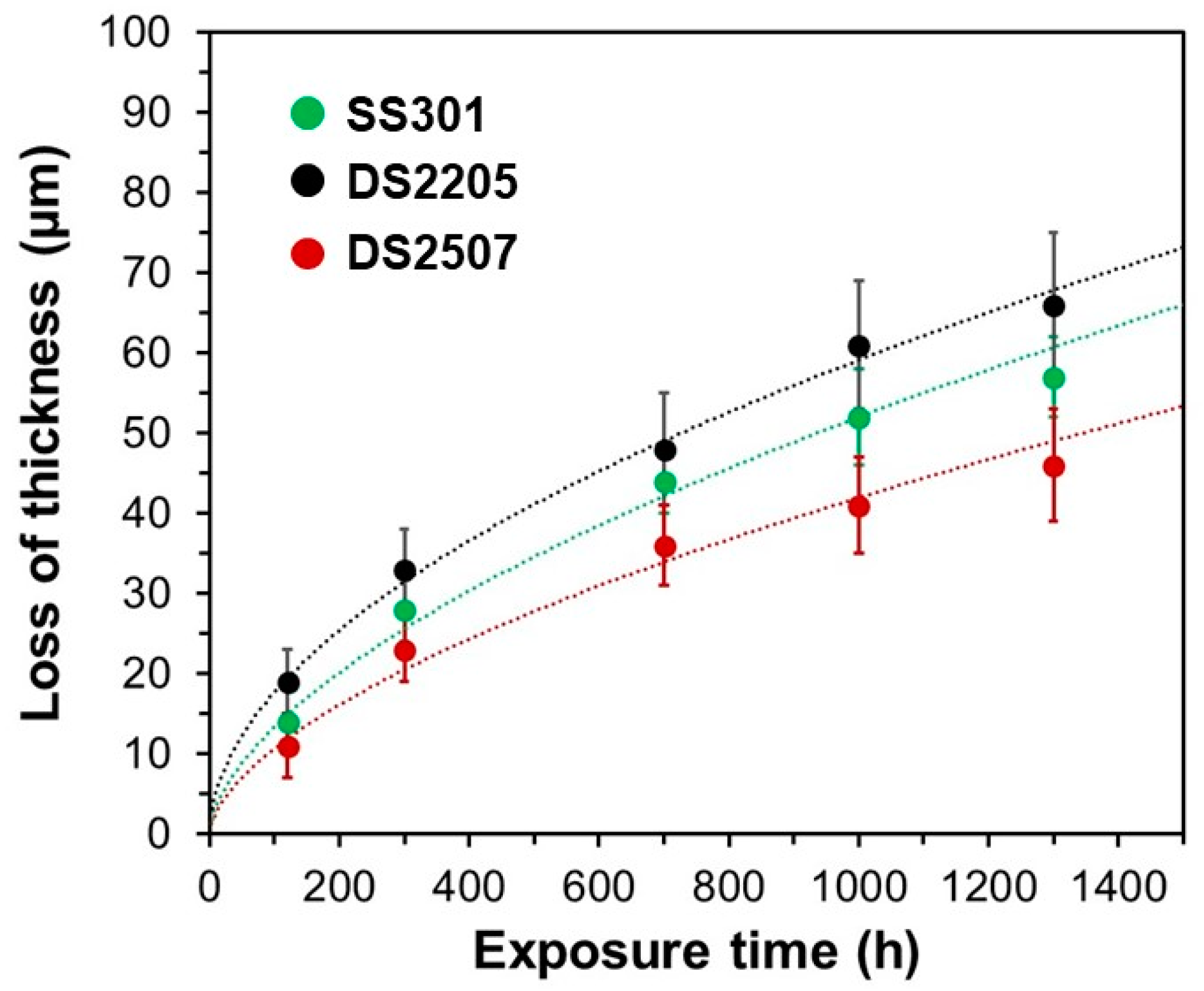
3.1. Corrosion Rates

Figure 1 exhibits the thickness loss evolution of the three steels as a function of the exposure time to molten salts. The thickness loss of the alloys in molten carbonate salts at 600 °C increased in the following order: DS2507 < SS301 < DS2205. From this tendency, it can be established that the corrosion resistance of the tested steels is mainly enhanced due to their nickel content (Table 1). In this sense, the thickness loss of DS2205 (5.2 Ni wt%) was higher than that of DS2507 and SS301 with 7.4 and 7.2 Ni (wt%), respectively. However, the corrosion resistance of DS2507 (25.0 Cr wt% and 3.8 Mo wt%) was better than SS301 (17.2 Cr wt% and 0.1 Mo wt%). Therefore, chromium and molybdenum contents also contributed to afford higher corrosion resistance and lower corrosion rate.
Since the tendency of loss thickness was not linear, it evidenced that the metal was oxidized very quickly in the first tens and hundreds of hours, and after a certain exposure time, the corrosion rate was reduced to lower values. Thus, the corrosion rates of the alloys were decreased with the increase in exposure time, reaching high values at the initial times and lower values after hundreds of hours. According to these tendencies of corrosion kinetics, the evolution of the metal loss with exposure time followed a parabolic law for SS301 and duplex stainless steels. The obtained k, n and R-squared (R2) values of trend for plots determined from Equation (2) with n close to 0.5 are summarized in Table 2. The R2 values were calculated to determine the reliability of the trends. The relatively good R2 values confirmed an acceptable fitting of the thickness loss of metal with the exposure time, and therefore, the corrosion kinetics of alloys can be associated to a parabolic law. This kinetics law represents a certain limitation of cation diffusion at the oxide scales and can be attributed to the effectivity of the protected oxide layers generated during the corrosion tests.
As typically presented in the International System, the corrosion rates are expressed as the value of metal thickness loss in mm/year, which allows a comparison with other alloys reported in previous works. In the present work, the initial corrosion rate was estimated by determining the slope of the loss thickness curves for the first points from 0 to 300 h and from 700 to 1300 h. The values of the corrosion rates for each steel exposed to molten carbonate salts at 600 °C are listed in Table 3. To the best of the authors’ knowledge, no previous work has reported on the corrosion rates of SS301, DS2205 and DS2507 immersed in molten carbonate salts at 600 °C. However, some studies presented the results of corrosion rates using other stainless steels in contact with carbonate salts (Table 4). For instance, Gallardo-González et al. [26] estimated corrosion rates between 0.22 and 2.07 mm/year for the AISI 316 stainless steel (with higher Ni content compared to the SS301, DS2205 and 2507, but lower chromium and molybdenum than duplex alloys) exposed to several compositions of carbonate salts at 600 °C. More recently, Prieto et al. [18] reported the corrosion rates of two austenitic stainless steels immersed in ternary eutectic carbonate salt at 700 °C: 0.18–0.21 mm/year for AISI 310H and 0.26-0.29 mm/year for AISI 347H. Although both AISI 310H and AISI 347H presented much higher Ni content than the steels of the present work, their values of corrosion rates at 700 °C were quite close to those obtained at 600 °C in our study. Taking into account these references, the behavior of the three stainless steels studied in this work suggests a corrosion resistance in molten carbonate salts at 600 °C close to austenitic stainless steels, but with less content in Ni. Thus, it could provide a remarkable cost reduction compared to austenitic steels with higher Ni, and therefore, DS2507 would be particularly interesting for a future application.

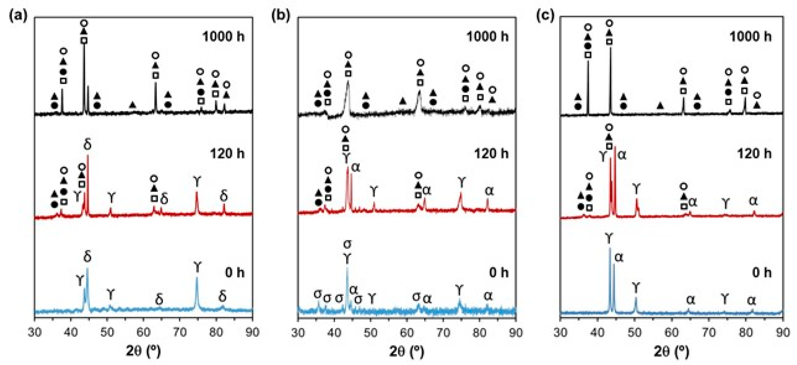
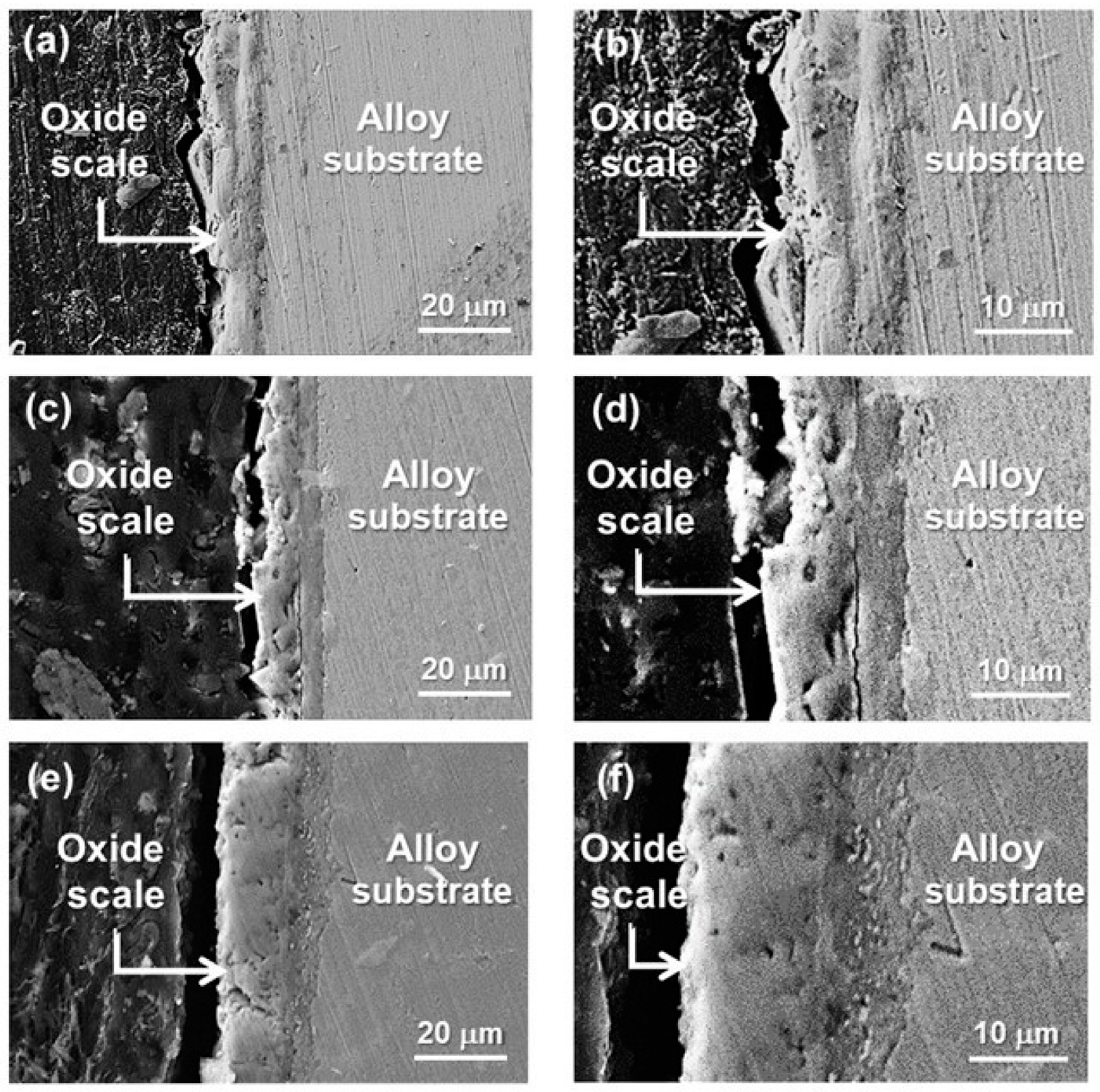
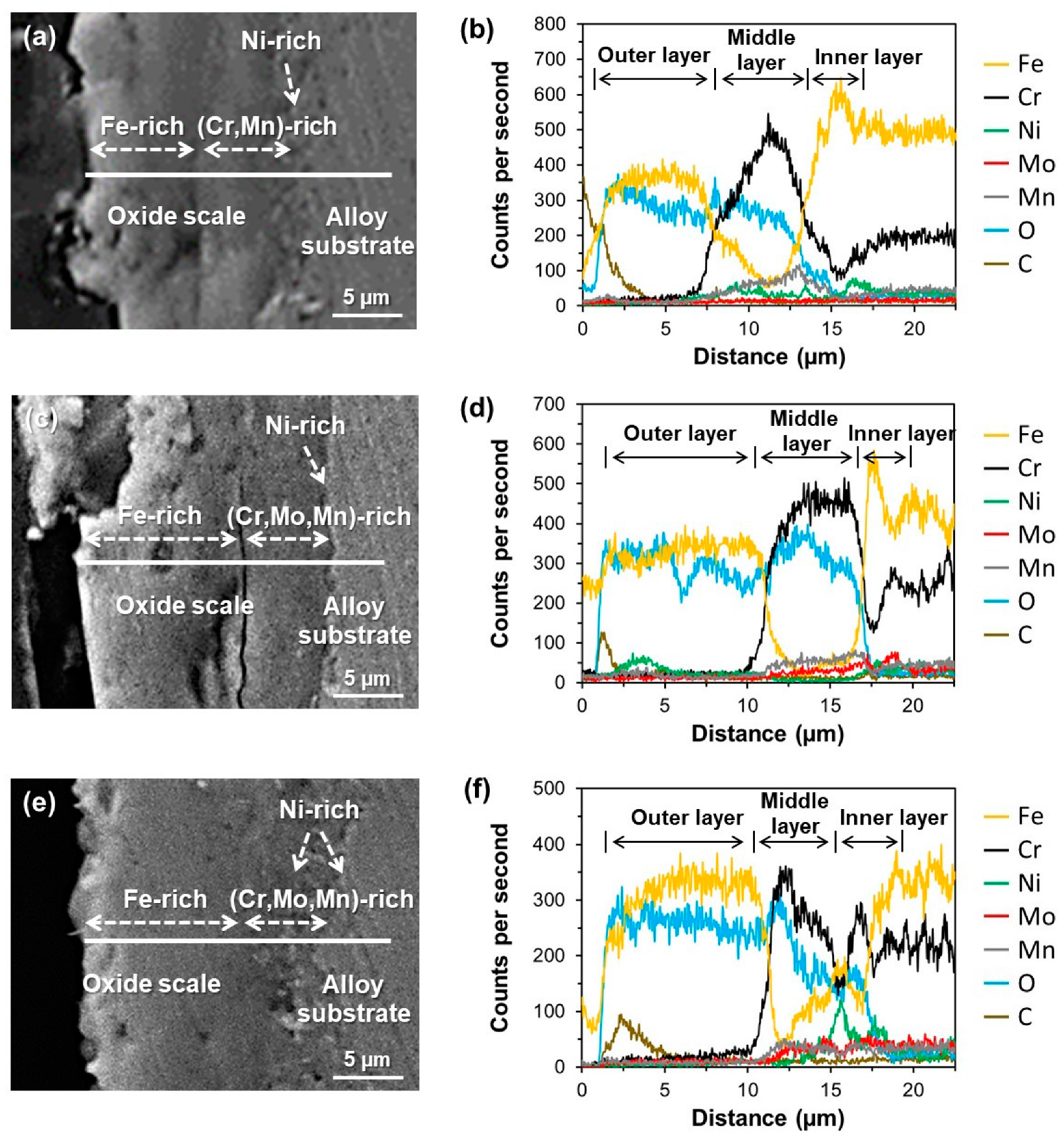
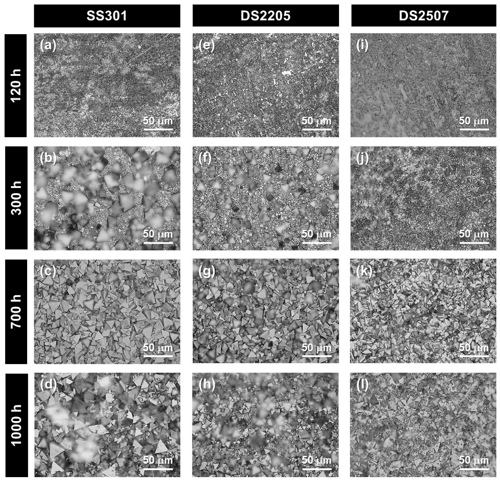
3.2. Composition and Microstructure of Oxide Scales

Figure 2 exhibits the XRD spectra of the SS301, DS2205 and DS2507 oxide scales after 120 h and 1000 h of exposure to molten salts. In addition, the XRD spectra of as-received steels (before corrosion tests) are added as a reference to distinguish the characteristic patterns of each alloy and those of the oxide scales. The as-received steels presented the δ and γ phases for SS301; the α, γ and σ phases for DS2205; and the α and γ phases for DS2507. After exposing the alloys for 120 h, the oxide scale peaks corresponding to chromium oxides (e.g., FeCr2O4 and LiCrO2), iron oxides (e.g., LiFeO2) and NiO were detected in the three steels. After 1000 h, no significant change in the nature of oxide phases was observed, but their presence was increased with the exposure time, since their relative peak intensities were increased concerning steels exposed for 120 h. Li-containing corrosion products, such as LiFeO2 and LiCrO2, were detected in the oxide scales of the three steels, which was in good agreement with previous works reported for other austenitic stainless steels under similar atmospheres [50,51,52,53]. The presence of LiFeO2 did not offer good protection from the corrosion because this compound tends to form porous oxide layers, which can accelerate the corrosion process. In contrast, the formation of NiO and FeCr2O4 are considered to have a good protective character [53]. The distribution of these compounds in the multilayered systems of the oxide scales will be studied by SEM. Nevertheless, it is important to note that the low molecular weight of lithium hinders its detection by SEM, and therefore, the formation of Li-containing corrosion products was only studied by XRD.
Figure 3 shows the cross-sectional SEM images of the SS301, DS2205 and DS2507 oxide scales formed after 1000 h, which had a thickness between 15 µm and 20 µm. In general, the oxide scales presented continuous and compact layers, but also exhibited some defects, such as pores, voids and vertical groves near the outer surfaces and at the interfaces of the inner oxide layers. The formation of pores and voids may be associated to the formation of LiFeO2-containing corrosion products [50,51,52,53,54]. The oxide scales of DS2205 exhibited a concentration of defects significantly higher than those of SS301 and DS2507. DS2205 also presented a partial delamination at the interface of the inner and outer layers as well as the internal fracture and visible detachments of the outer oxide scale in some regions. The lower Ni content in DS2205 could accelerate its corrosion process as well as the formation of porosity and other defects. Thus, the results of the thickness and aspect of the oxide scales after 1000 h (Figure 3) and the corrosion rates determined for the same period (Figure 1) lead to the assumption that detachment processes of this corrosion layer have occurred in all steels.
Figure 4 shows the SEM–EDS line scans of the oxide layers formed on the SS301, DS2205 and DS2507 surfaces after the corrosion tests for 1000 h. The oxide scales presented an arranged multilayer system on the surface of the steels after 1000 h of the corrosion process. The outer layer was mainly composed of Fe and O; the middle layer was enriched in Cr, Mn and O; and the inner layer was significantly enriched in a non-homogeneous amount of Ni, Mn, Mo and O. Thus, the analyses evidenced an arranged multilayer system with LiFeO2, LiCrO2, FeCr2O4 and NiO as the main compounds from molten salt to metallic substrate. While the Fe-rich outer layer (LiFeO2) was a large generation zone of defects, such as micrometer pores and voids, the Ni-rich inner layer was a narrow transition zone between the middle layer (LiCrO2) and metal, which can be considered as an internal oxidation region. In addition to Ni-enrichment at the inner layer, it also presented an enrichment of Cr for DS2507 but also a peak of Fe and a depletion of Cr for SS301 and DS2205, which could explain the best corrosion resistance of DS2507. Therefore, the enrichment in Cr, Ni and Mo oxides near the oxide/metal interface of steels could play an important role as a barrier against further oxidation and also enhance the adhesion between the oxide scale and metallic substrate.

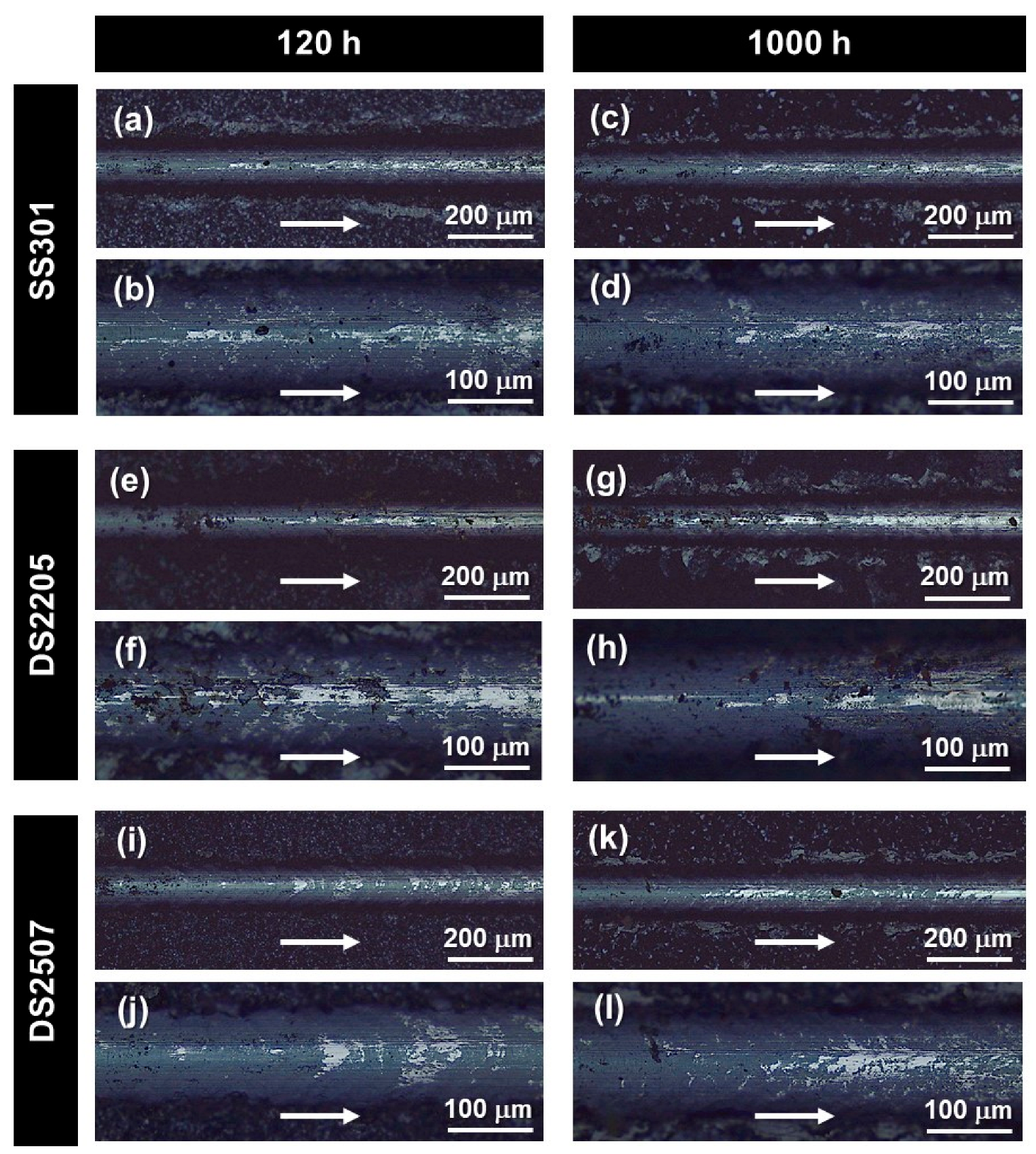
3.3. Mechanical Integrity of Oxide Scales

Generally, the corrosion resistance, particularly in molten salts, is associated with a good mechanical integrity of the oxide scales as well as their adhesion to the metallic substrate, which could avoid their detachment in service and contribute to decreasing the corrosion process [54,55]. Thus, the analysis of the tracks of the scratch test is a suitable way to determine their mechanical integrity and adhesion. Figure 5 shows the scratch tracks for the oxide scales of the steels. At the initial zone of the scratch tracks, observing only the oxide scale, the DS2205 samples presented a higher concentration of defects (voids and some transversal micro-cracks) than SS301 and DS2507. This was in agreement with the cross-sectional SEM images and suggested an unsatisfactory mechanical integrity of the oxide scales [56]. The concentration of both voids and micro-cracks was similar in each alloy exposed for 120 h and 1000 h, and therefore, the mechanical integrity of the oxide scales was stable with the time of immersion. On the other side, at the intermediate zone of the scratch where coexisted both an oxide layer and a substrate at the scratch valley, a progressive removal of the oxide layer without decohesion of the scale–substrate interface was observed at both samples after 120 h and 1000 h. This failure mechanism suggested that the oxide scales of the three steels presented a good adhesion to the metallic substrate. Thus, these results were in good agreement with the defects of the oxide scales observed in the outer and inner layers of the oxide scales, particularly in the DS2205 samples, as well as the satisfactory adhesion at the oxide-metal interface of all samples in Figure 3 and Figure 4.

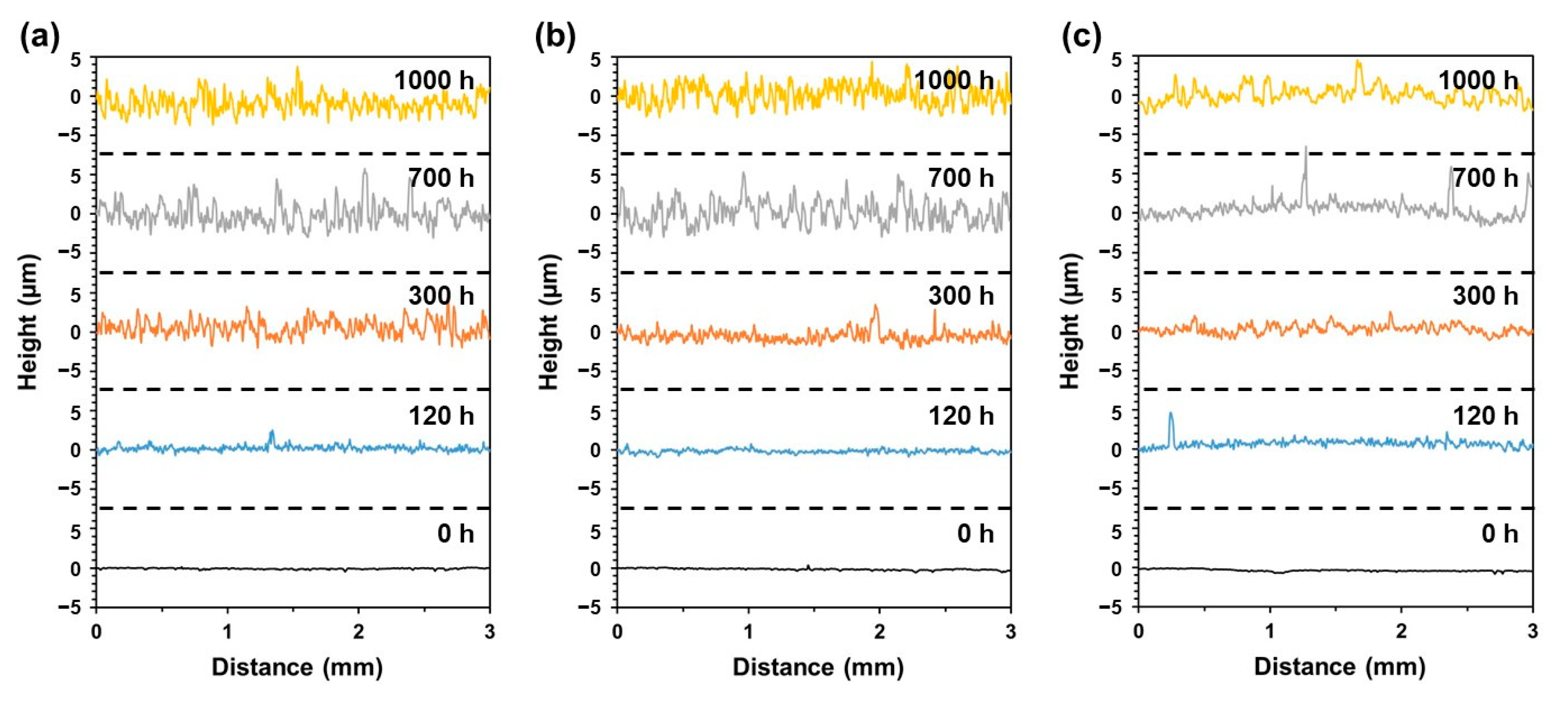
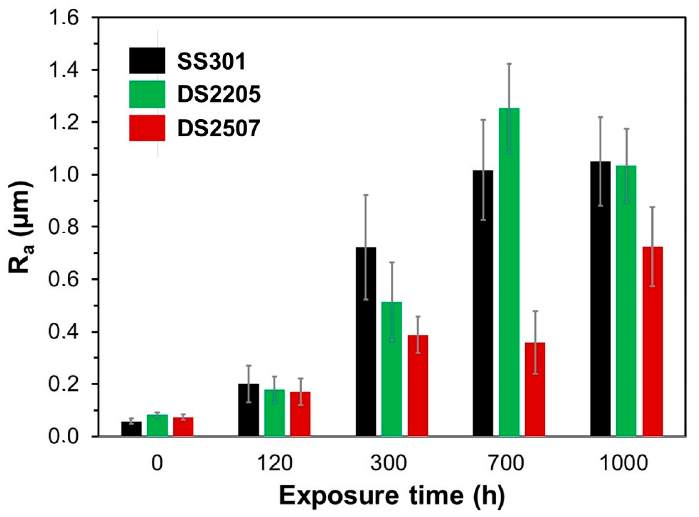
3.4. Surface Topography of Oxide Scales

The surface topography of the oxide scales may be a critical parameter for a possible implementation of these steels in CSP plants. In this sense, the molten salts flow through different components of CSP-like tubes, pipe and tanks, generating a certain friction force between the metal surface and the molten salt. A surface with a poor flatness and high roughness can increase the friction between the oxide scale and molten salt; therefore, it could contribute to the detachment of oxide scales in operation.
Figure 6 shows the top surface images of the oxide scales, obtained from optical microscopy, formed after exposing the samples to molten salts for 120 h, 300 h, 700 h and 1000 h. It was observed that the size of the crystalline grains of the oxide scales for each alloy were continuously enlarged with the increase of the exposure time in molten salts. In addition, the surface of the scales also presented an increase in irregularities and presence of remarkable hills and valleys from 300 h.
Figure 7 and Figure 8 exhibit the topographic profiles and the surface roughness parameter (Ra) of the oxide scales, obtained from contact profilometer, formed after exposing the samples to molten salts between 120 h and 1000 h. As expected, the polished surfaces of the as-prepared samples used as references presented a typical surface roughness from the grinding process (<0.1 µm) with a considerable flat topographical profile. In contrast, after 300 h of exposure to the molten salts, the surfaces of the scales exhibited a larger roughness with significant irregularities in height and the presence of strong hills and valleys. This could be the result of the oxide layer in this first stage of corrosion being formed with preferential chemical attack in those regions with defects or high surface energy. This strongly irregular topography was significantly raised with the increased exposure time. The samples immersed for 700 h and 1000 h exhibited the surfaces with the most roughness. On the other side, the oxide scales of DS2507 showed a lower roughness and flatter oxide layers than SS301 and DS2205, which exhibited quite similar topographic profiles with the exposure time as well as roughness values.

4. Conclusions

Austenitic stainless steel 301LN and duplex stainless steels from grades 2205 and 2507 were evaluated for their compatibility with eutectic Li2CO3-Na2CO3-K2CO3 (32/33/35 wt%) molten salts at 600 °C in air during a long-term period for thermal energy storage applications. The corrosion kinetics of steels follows a parabolic law. The corrosion rate was determined from the metal thickness loss, obtaining values in the order of 0.19–0.69, 0.22–1.02 and 0.17–0.59 mm/year for SS301, DS2205 and DS2507, respectively. Therefore, DS2507 presented a higher corrosion resistance than SS301 and DS2205.
The analyses of the oxide scales evidenced an arranged multilayer system formed of LiFeO2, LiCrO2, FeCr2O4 and NiO as the main compounds found in the different layers from the molten salt to metal-scale interface. The Fe-rich outer layer (LiFeO2) exhibited a remarkable concentration of cracks, porosity and voids, which decreased the mechanical integrity of the oxide scales and accelerated the corrosion process. In contrast, the Ni-rich inner layer was a narrow transition zone between the middle layer (LiCrO2 and FeCr2O4) and metal substrate. In addition to Ni-enrichment at the inner layer, it also presented an enrichment of Cr for DS2507, but a peak of Fe and a Cr depletion for SS301 and DS2205, which could explain the best corrosion resistance of DS2507. However, the inner layers of the oxide scales for the three steels presented good adhesion to the metallic substrate. On the other side, the oxide scales of DS2507 exhibited lower surface roughness and a flatter oxide layer than those of SS301 and DS2205. In conclusion, among the steels studied in this work, super duplex stainless steel 2507 may be proposed as the most promising alternative for thermal energy storage of those structural components in CSP plants that usually work with eutectic Li2CO3-Na2CO3-K2CO3 molten salt at 600 °C in air.
Further work will be focused on the deeper understanding of the involved corrosion mechanisms as well as exploring strategies for the development of protective oxide films to mitigate and inhibit the oxidation of duplex stainless steels immersed in molten carbonate salts.

Author Contributions

Conceptualization, M.M. and M.C.-A.; methodology, M.M., L.C. and M.C.-A.; software, M.M., L.C. and M.C.-A.; validation, M.M. and M.C.-A.; formal analysis, M.M. and M.C.-A.; investigation, M.M., M.C.-A. and A.M.; resources, M.M., L.C., G.F. and A.M.; data curation, M.M., M.C.-A. and G.F.; writing—original draft preparation, M.M.; writing—review and editing, M.M., L.C., M.C.-A., G.F. and A.M.; visualization, M.M. and M.C.-A.; supervision, M.M. and A.M.; project administration, M.M.; funding acquisition, L.L. and A.M. All authors have read and agreed to the published version of the manuscript.

Funding

This research was funded by Direcció General d’Indústria and ACCIÓ (Generalitat de Catalunya) to IMEM-CIEFMA in the INNOTEC project with grant number ACE034/21/000031. Laura Cabezas acknowledges the Ph.D. scholarship received from the Spanish Ministerio de Ciencia e Innovación MICINN—FEDER (Spain) through Grant PRE2020-092445. Miguel Morales Comas thanks the Serra Hunter programme of the Generalitat de Catalunya.

Data Availability Statement

Not applicable.

Conflicts of Interest

The authors declare no conflict of interest.

References

  1. Liu, M.; Steven Tay, N.H.; Bell, S.; Belusko, M.; Jacob, R.; Will, G.; Saman, W.; Bruno, F. Review on Concentrating Solar Power Plants and New Developments in High Temperature Thermal Energy Storage Technologies. Renew. Sustain. Energy Rev. 2016, 53, 1411–1432. [Google Scholar] [CrossRef]
  2. Lovegrove, K.; Csiro, W.S. Introduction to Concentrating Solar Power (CSP) Technology. Conc. Sol. Power Technol. 2012, 3–15. [Google Scholar] [CrossRef]
  3. Lovegrove, K.; Pye, J. Fundamental Principles of Concentrating Solar Power (CSP) Systems. Conc. Sol. Power Technol. 2012, 16–67. [Google Scholar] [CrossRef]
  4. Liu, M.; Saman, W.; Bruno, F. Review on Storage Materials and Thermal Performance Enhancement Techniques for High Temperature Phase Change Thermal Storage Systems. Renew. Sustain. Energy Rev. 2012, 16, 2118–2132. [Google Scholar] [CrossRef]
  5. Cabeza, L.F.; Gutierrez, A.; Barreneche, C.; Ushak, S.; Fernández, Á.G.; Inés Fernádez, A.; Grágeda, M. Lithium in Thermal Energy Storage: A State-of-the-Art Review. Renew. Sustain. Energy Rev. 2015, 42, 1106–1112. [Google Scholar] [CrossRef] [Green Version]
  6. Bauer, T.; Pfleger, N.; Laing, D.; Steinmann, W.D.; Eck, M.; Kaesche, S. High-Temperature Molten Salts for Solar Power Application. Molten Salts Chem. 2013, 415–438. [Google Scholar] [CrossRef]
  7. Mao, Q.; Zhang, L.; Wu, H.; Liu, X. Design and calculation of a new storage tank for concentrating solar power plant Energy. Convers. Manag. 2015, 100, 414–418. [Google Scholar] [CrossRef]
  8. Parrado, C.; Marzo, A.; Fuentealba, E.; Fernández, A.G. 2050 LCOE Improvement Using New Molten Salts for Thermal Energy Storage in CSP Plants. Renew. Sustain. Energy Rev. 2016, 57, 505–514. [Google Scholar] [CrossRef]
  9. Ding, W.; Bauer, T. Progress in Research and Development of Molten Chloride Salt Technology for Next Generation Concentrated Solar Power Plants. Engineering 2021, 7, 334–347. [Google Scholar] [CrossRef]
  10. Sarvghad, M.; Delkasar Maher, S.; Collard, D.; Tassan, M.; Will, G.; Steinberg, T.A. Materials Compatibility for the next Generation of Concentrated Solar Power Plants. Energy Storage Mater. 2018, 14, 179–198. [Google Scholar] [CrossRef]
  11. Gomez, J.C. High-Temperature Phase Change Materials (PCM) Candidates for Thermal Energy Storage (TES) Applications; National Renewable Energy Lab. (NREL): Golden, CO, USA, 2011. [CrossRef] [Green Version]
  12. Kenisarin, M.M. High-Temperature Phase Change Materials for Thermal Energy Storage. Renew. Sustain. Energy Rev. 2010, 14, 955–970. [Google Scholar] [CrossRef]
  13. Myers, P.D.; Goswami, D.Y. Thermal Energy Storage Using Chloride Salts and Their Eutectics. Appl. Therm. Eng. 2016, 109, 889–900. [Google Scholar] [CrossRef] [Green Version]
  14. Mehos, M.; Turchi, C.; Vidal, J.; Wagner, M.; Ma, Z.; Ho, C.; Kolb, W.; Andraka, C.; Kruizenga, A. Concentrating Solar Power Gen3 Demonstration Roadmap. In NREL/TP-5500-67464; NREL: Golden, CO, USA, 2017; pp. 1–140. [Google Scholar] [CrossRef] [Green Version]
  15. Turchi, C.S.; Vidal, J.; Bauer, M. Molten Salt Power Towers Operating at 600–650 °C: Salt Selection and Cost Benefits. Sol. Energy 2018, 164, 38–46. [Google Scholar] [CrossRef]
  16. Nunes, V.M.B.; Lourenço, M.J.V.; Santos, F.J.V.; Nieto de Castro, C.A. Molten Alkali Carbonates as Alternative Engineering Fluids for High Temperature Applications. Appl. Energy 2019, 242, 1626–1633. [Google Scholar] [CrossRef]
  17. Fereres, S.; Prieto, C.; Giménez-Gavarrell, P.; Rodríguez, A.; Sánchez-Jiménez, P.E.; Pérez-Maqueda, L.A. Molten Carbonate Salts for Advanced Solar Thermal Energy Power Plants: Cover Gas Effect on Fluid Thermal Stability. Sol. Energy Mater. Sol. Cells 2018, 188, 119–126. [Google Scholar] [CrossRef]
  18. Prieto, C.; Fereres, S.; Ruiz-Cabañas, F.J.; Rodriguez-Sanchez, A.; Montero, C. Carbonate Molten Salt Solar Thermal Pilot Facility: Plant Design, Commissioning and Operation up to 700 °C. Renew. Energy 2020, 151, 528–541. [Google Scholar] [CrossRef]
  19. Mineral Requirements for Clean Energy Transitions—The Role of Critical Minerals in Clean Energy Transitions—Analysis—IEA. Available online: https://www.iea.org/reports/the-role-of-critical-minerals-in-clean-energy-transitions/mineral-requirements-for-clean-energy-transitions (accessed on 31 August 2022).
  20. Greim, P.; Solomon, A.A.; Breyer, C. Assessment of Lithium Criticality in the Global Energy Transition and Addressing Policy Gaps in Transportation. Nat. Commun. 2020, 11, 1–11. [Google Scholar] [CrossRef]
  21. U.S. Department of Energy. Federal Consortium for Advanced Batteries. National Blueprint for Lithium Batteries Executive Summary 2021–2030, 2021, pp. 1–24. Available online: www.energy.gov/eere/vehicles (accessed on 14 December 2022).
  22. Beyond Lithium: Other Potential Technologies That Battery Manufacturers Are Betting on | CIC EnergiGUNE. Available online: https://cicenergigune.com/en/blog/beyond-lithium-technologies-battery-manufacturers (accessed on 31 August 2022).
  23. Chi, X.; Zhang, Y.; Hao, F.; Kmiec, S.; Dong, H.; Xu, R.; Zhao, K.; Ai, Q.; Terlier, T.; Wang, L.; et al. An Electrochemically Stable Homogeneous Glassy Electrolyte Formed at Room Temperature for All-Solid-State Sodium Batteries. Nat. Commun. 2022, 13, 1–11. [Google Scholar] [CrossRef]
  24. Sarvghad, M.; Steinberg, T.A.; Will, G. Corrosion of Steel Alloys in Eutectic NaCl+Na2CO3 at 700 °C and Li2CO3+K2CO3+Na2CO3 at 450 °C for Thermal Energy Storage. Sol. Energy Mater. Sol. Cells 2017, 170, 48–59. [Google Scholar] [CrossRef]
  25. Sarvghad, M.; Will, G.; Steinberg, T.A. Corrosion of Inconel 601 in Molten Salts for Thermal Energy Storage. Sol. Energy Mater. Sol. Cells 2017, 172, 220–229. [Google Scholar] [CrossRef]
  26. Gallardo-González, J.; Martínez, M.; Barreneche, C.; Fernández, A.I.; Liu, M.; Tay, N.H.S.; Bruno, F.; Segarra, M. Corrosion of AISI316 as Containment Material for Latent Heat Thermal Energy Storage Systems Based on Carbonates. Sol. Energy Mater. Sol. Cells 2018, 186, 1–8. [Google Scholar] [CrossRef]
  27. Sah, S.P. Corrosion of 304 Stainless Steel in Carbonates Melt– a State of Enhanced Dissolution of Corrosion Products. Corros. Sci. 2020, 169, 108535. [Google Scholar] [CrossRef]
  28. de Miguel, M.T.; Encinas-Sánchez, V.; Lasanta, M.I.; García-Martín, G.; Pérez, F.J. Corrosion Resistance of HR3C to a Carbonate Molten Salt for Energy Storage Applications in CSP Plants. Sol. Energy Mater. Sol. Cells 2016, 157, 966–972. [Google Scholar] [CrossRef]
  29. Fernández, A.G.; Pineda, F.; Walczak, M.; Cabeza, L.F. Corrosion Evaluation of Alumina-Forming Alloys in Carbonate Molten Salt for CSP Plants. Renew. Energy 2019, 140, 227–233. [Google Scholar] [CrossRef]
  30. Grosu, Y.; Anagnostopoulos, A.; Navarro, M.E.; Ding, Y.; Faik, A. Inhibiting Hot Corrosion of Molten Li2CO3+K2CO3+Na2CO3 Salt through Graphitization of Construction Materials for Concentrated Solar Power. Sol. Energy Mater. Sol. Cells 2020, 215, 110650. [Google Scholar] [CrossRef]
  31. Rouillard, F.; Charten, F.; Moine, G. Corrosion Behavior of Different Metallic Materials in Supercritical Carbon Dioxide at 550 °C and 250 Bars. Corrosion 2011, 67, 095001–095007. [Google Scholar] [CrossRef]
  32. Chan, K.W.; Tjong, S.C. Effect of Secondary Phase Precipitation on the Corrosion Behavior of Duplex Stainless Steels. Materials 2014, 7, 5268–5304. [Google Scholar] [CrossRef] [Green Version]
  33. Solomon, H.D. Stainless Steels: Duplex. Encycl. Mater. Sci. Technol. 2001, 8802–8804. [Google Scholar] [CrossRef]
  34. Paulraj, P.; Garg, R. Effect Of Intermetallic Phases On Corrosion Behavior And Mechanical Properties Of Duplex Stainless Steel And Super-Duplex Stainless Steel. Adv. Sci. Technol. Res. J. 2015, 9, 87–105. [Google Scholar] [CrossRef]
  35. Sarvghad, M.; Will, G.; Steinberg, T.A. Corrosion of Steel Alloys in Molten NaCl + Na2SO4 at 700 °C for Thermal Energy Storage. Sol. Energy Mater. Sol. Cells 2018, 179, 207–216. [Google Scholar] [CrossRef]
  36. Llanes, L.; Mateo, A.; Villechaise, P.; Méndez, J.; Anglada, M. Effect of Testing Atmosphere (Air/in Vacuo) on Low Cycle Fatigue Characteristics of a Duplex Stainless Steel. Int. J. Fatigue 1999, 21, S119–S125. [Google Scholar] [CrossRef]
  37. Gironès, A.; Villechaise, P.; Mateo, A.; Anglada, M.; Méndez, J. EBSD Studies on the Influence of Texture on the Surface Damage Mechanisms Developed in Cyclically Loaded Aged Duplex Stainless Steels. Mater. Sci. Eng. A 2004, 387–389, 516–521. [Google Scholar] [CrossRef]
  38. Fargas, G.; Akdut, N.; Anglada, M.; Mateo, A. Microstructural Evolution during Industrial Rolling of a Duplex Stainless Steel. ISIJ Int. 2008, 48, 1596–1602. [Google Scholar] [CrossRef] [Green Version]
  39. Fargas, G.; Anglada, M.; Mateo, A. Effect of the Annealing Temperature on the Mechanical Properties, Formability and Corrosion Resistance of Hot-Rolled Duplex Stainless Steel. J. Mater. Process. Technol. 2009, 209, 1770–1782. [Google Scholar] [CrossRef]
  40. Verma, J.; Taiwade, R.V. Effect of Welding Processes and Conditions on the Microstructure, Mechanical Properties and Corrosion Resistance of Duplex Stainless Steel Weldments—A Review. J. Manuf. Process. 2017, 25, 134–152. [Google Scholar] [CrossRef]
  41. Besharatloo, H.; Carpio, M.; Cabrera, J.M.; Mateo, A.M.; Fargas, G.; Wheeler, J.M.; Roa, J.J.; Llanes, L. Novel Mechanical Characterization of Austenite and Ferrite Phases within Duplex Stainless Steel. Metals 2020, 10, 1352. [Google Scholar] [CrossRef]
  42. Maslak, M.; Stankiewicz, M.; Slazak, B. Duplex Steels Used in Building Structures and Their Resistance to Chloride Corrosion. Materials 2021, 14, 5666. [Google Scholar] [CrossRef]
  43. Morales, M.; Chimenos, J.M.; Fernández, A.I.; Segarra, M. Materials Selection for Superheater Tubes in Municipal Solid Waste Incineration Plants. J. Mater. Eng. Perform. 2014, 23, 3207–3214. [Google Scholar] [CrossRef]
  44. Mateo, A.; Heredero, F.; Fargas, G. Failure Investigation of a Centrifuge Duplex Stainless Steel Basket. Eng. Fail. Anal. 2011, 18, 2165–2178. [Google Scholar] [CrossRef]
  45. Hara, T.; Semba, H.; Amaya, H. Pipe and Tube Steels for Oil and Gas Industry and Thermal Power Plant. Encycl. Mater. Met. Alloy. 2022, 2, 140–152. [Google Scholar] [CrossRef]
  46. Wu, Y.T.; Ren, N.; Wang, T.; Ma, C.F. Experimental Study on Optimized Composition of Mixed Carbonate Salt for Sensible Heat Storage in Solar Thermal Power Plant. Sol. Energy 2011, 85, 1957–1966. [Google Scholar] [CrossRef]
  47. Chen, C.; Tran, T.; Olivares, R.; Wright, S.; Sun, S. Coupled Experimental Study and Thermodynamic Modeling of Melting Point and Thermal Stability of Li2CO3+K2CO3+Na2CO3 Based Salts. J. Sol. Energy Eng. Trans. ASME 2014, 136, 031017–031024. [Google Scholar] [CrossRef]
  48. Itoh, M. Time-Dependent Power Laws in the Oxidation and Corrosion of Metals and Alloys. Sci. Rep. 2022, 12, 6944–6953. [Google Scholar] [CrossRef] [PubMed]
  49. Morcillo, M.; Chico, B.; Díaz, I.; Cano, H.; De La Fuente, D. Atmospheric Corrosion Data of Weathering Steels. A Review. Corros. Sci. 2013, 77, 6–24. [Google Scholar] [CrossRef] [Green Version]
  50. Tan, L.; Yang, Y.; Allen, T.R. Oxidation Behavior of Iron-Based Alloy HCM12A Exposed in Supercritical Water. Corros. Sci. 2006, 48, 3123–3138. [Google Scholar] [CrossRef]
  51. Biedenkopf, P.; Spiegel, M.; Grabke, H.J. The corrosion behavior of Fe-Cr alloys containing Co, Mn, and/or Ni and of a Co-base alloy in the presence of molten (Li, K)-carbonate. Mater. Corros. 1997, 48, 731–743. [Google Scholar] [CrossRef]
  52. Biedenkopf, P.; Bischoff, M.M.; Wochner, T. Corrosion phenomena of alloys and electrode materials in molten carbonate fuel cells. Mater. Corros. 2000, 51, 287–302. [Google Scholar] [CrossRef]
  53. Dorcheh, A.S.; Durham, R.N.; Galetz, M.C. Corrosion behavior of stainless and low-chromium steels and IN625 in molten nitrate salts at 600 °C. Sol. Energy Mater. Sol. Cells 2016, 144, 109–116. [Google Scholar] [CrossRef]
  54. Morales, M.; Gordon, S.; Fernández-Arana, Ó.; García-Marro, F.; Mateo, A.; Llanes, L.; Fargas, G. Duplex Stainless Steels for Thermal Energy Storage: Characterization of Oxide Scales Formed in Carbonate Salts at 500 °C. Metals 2022, 12, 2156. [Google Scholar] [CrossRef]
  55. Morales, M.; Chimenos, J.M.; Espiell, F.; Segarra, M. The Effect of Temperature on Mechanical Properties of Oxide Scales Formed on a Carbon Steel in a Simulated Municipal Solid Waste Incineration Environment. Surf. Coat. Technol. 2014, 238, 51–57. [Google Scholar] [CrossRef]
  56. Farhan, M.S. A Review on Adhesion Strength of Single and Multilayer Coatings and the Evaluation Method. Wasit J. Eng. Sci. 2016, 4, 1–27. [Google Scholar]
Figure 1. Evolution of thickness loss of SS301, DS2205 and DS2507 as a function of the exposure time in molten salts. The dot lines indicate the tendency curve of thickness loss for each alloy obtained using Equation (2).
Metals 12 02190 g001
Figure 2. XRD spectra and peak identification chart of oxide scales formed on the surfaces of (a) SS301, (b) DS2205 and (c) DS2507 after several exposure times to molten salts. The symbols denote the phases: α, δ, γ and σ (of metallic substrate); ○ α-LiFeO2 (JCPDS file cards no. 74-2284); ▲ LiCrO2 (JCPDS 24-0600); ● FeCr2O4 (JCPDS 34-0140); and □ NiO (JCPDS 47-1049).
Metals 12 02190 g002
Figure 3. Cross-sectional SEM images of (a,b) SS301, (c,d) DS2205 and (e,f) DS2507 samples exposed to molten salts for 1000 h.
Metals 12 02190 g003
Figure 4. Cross-sectional SEM images and EDS line-scan analyses corresponding to (a,b) SS301, (c,d) DS2205, and (e,f) DS2507 samples exposed to molten salts for 1000 h.
Metals 12 02190 g004
Figure 5. Optical microscopy images at two magnifications of scratch tracks on the oxide scale surface of (ad) SS301, (eh) DS2507 and (i–l) DS2205 after 120 h and 1000 h. The white arrow indicates the indenter sliding direction during the scratch test.
Metals 12 02190 g005
Figure 6. Surface images of the oxide scales, obtained from optical microscopy, formed on the (ad) SS301, (eh) DS2205 and (il) DS2507 after exposing to molten salts for different times.
Metals 12 02190 g006
Figure 7. Representative surface topographic profiles of the oxide scales, obtained from contact profilometer, formed on the (a) SS301, (b) DS2205 and (c) DS2507 after exposing to molten salts for different times.
Metals 12 02190 g007
Figure 8. Surface roughness parameter (Ra) of the oxide scales, determined from contact profilometer, formed on the SS301, DS2205 and DS2507 surfaces after exposing to molten salts for different times.
Metals 12 02190 g008
Table 1. Chemical composition of SS301 and duplex stainless steels 2205 and 2507 (in wt%).
SteelFeCrNiMoMnCNSiPS
SS301Bal.17.47.20.11.20.020.12<1.0<0.03<0.006
DS2205Bal.22.65.23.01.50.020.16<0.45<0.03<0.015
DS2507Bal.25.07.43.82.00.010.24<0.8<0.03<0.015
Table 2. Experimental parameters of Equation (2) after fitting the thickness loss of metal at the exposure times and R-squared values.
-SS301DS2205DS2507
k (µm·h−1/2)0.891.590.69
n0.580.520.59
R20.9870.9950.989
Table 3. Corrosion rates (CR) of tested steels in molten carbonate salts at 600 °C for each alloy.
SS301DS2205DS2507
CR (mm/year) from 0 to 300 h0.691.02 0.59
CR (mm/year) from 700 to 1300 h0.22 0.29 0.17
Table 4. Overview of corrosion rates (CR) of tested steels, indicating the Cr, Ni and Mo contents in carbonate salts in the range of 600 and 700 °C.
SampleCr
(wt%)
Ni
(wt%)
Mo
(wt%)
Li-Na-K2CO3 (wt%)Temp. (°C)CR (mm/year)Ref
AISI 301LN17.47.20.132/33/356000.22–0.69Present work
DS220522.65.23.00.29–1.02
DS250725.07.43.80.17–0.59
AISI 31617.0–18.510.5–13.52.0–2.510/35/556000.40–1.71[26]
16/31/53 0.32–2.07
33/38/29 0.22–1.03
AISI 310H24.0–26.019.0–22.0<0.132/33/357000.18–0.21[18]
AISI 347H17.0–20.09.0–13.0<0.10.26–0.29
Publisher’s Note: MDPI stays neutral with regard to jurisdictional claims in published maps and institutional affiliations.

