
Elimination of the Stray Grain Defects of Single Crystal Blade by Variable Wall Thickness Based on Integral Ceramic Mold

Abstract
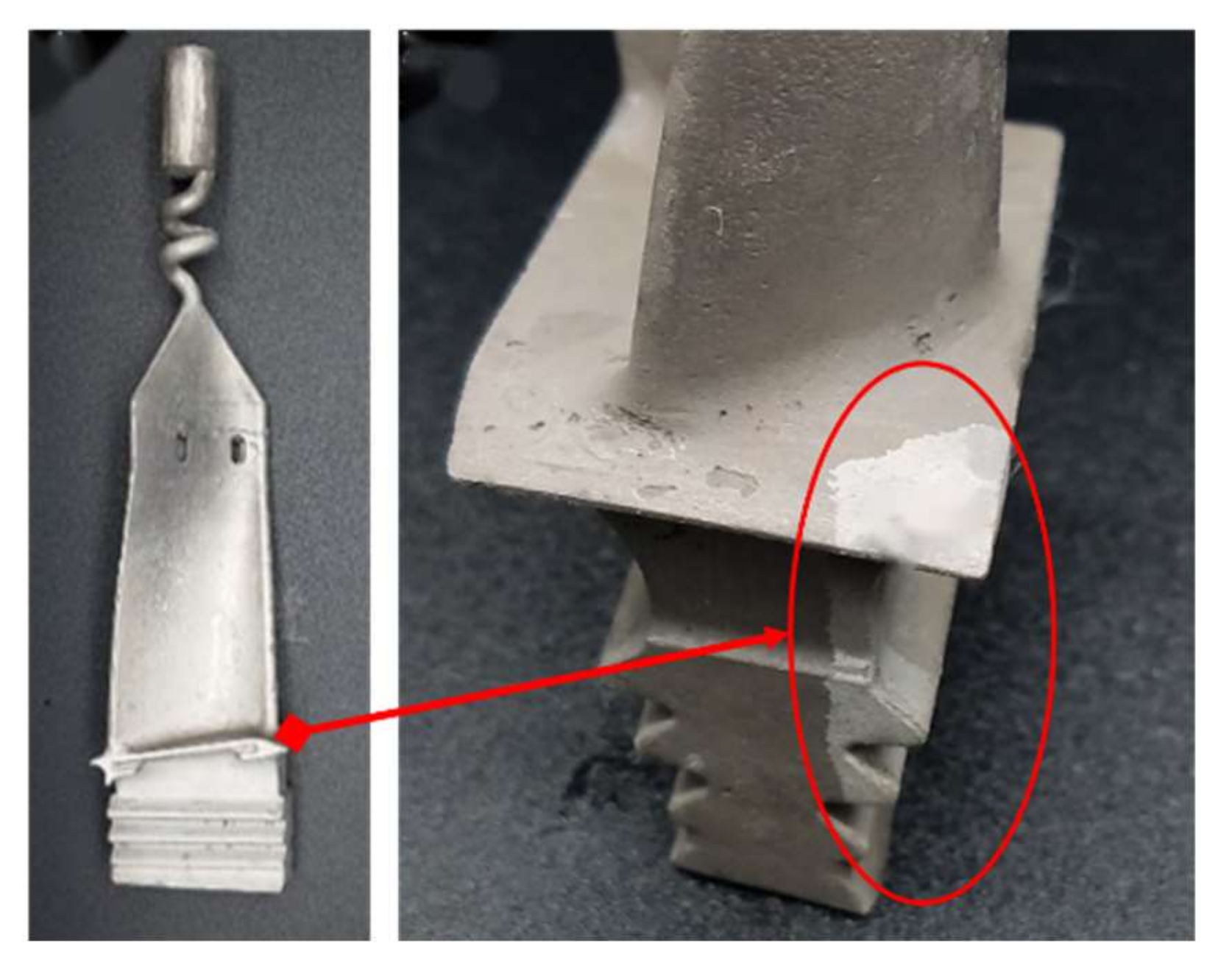
:1. Introduction
2. Materials and Methods
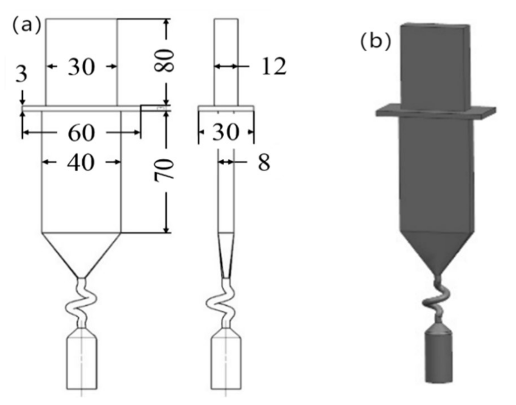
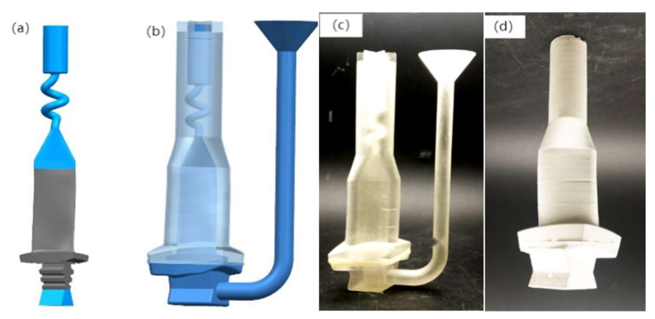
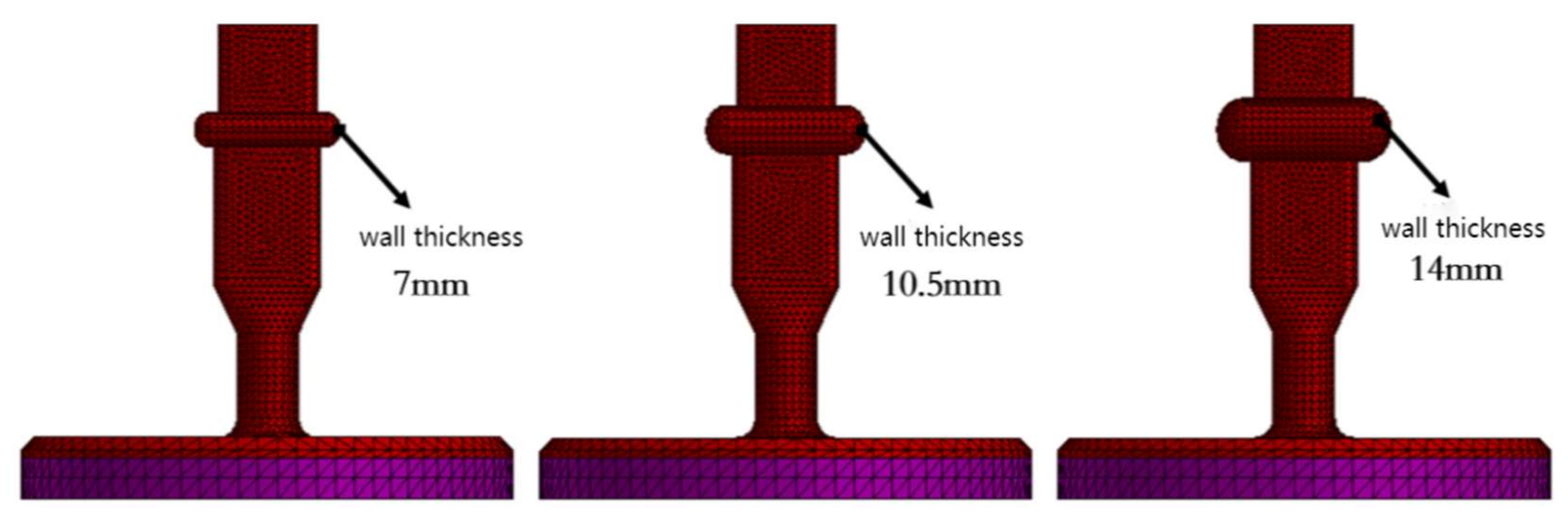
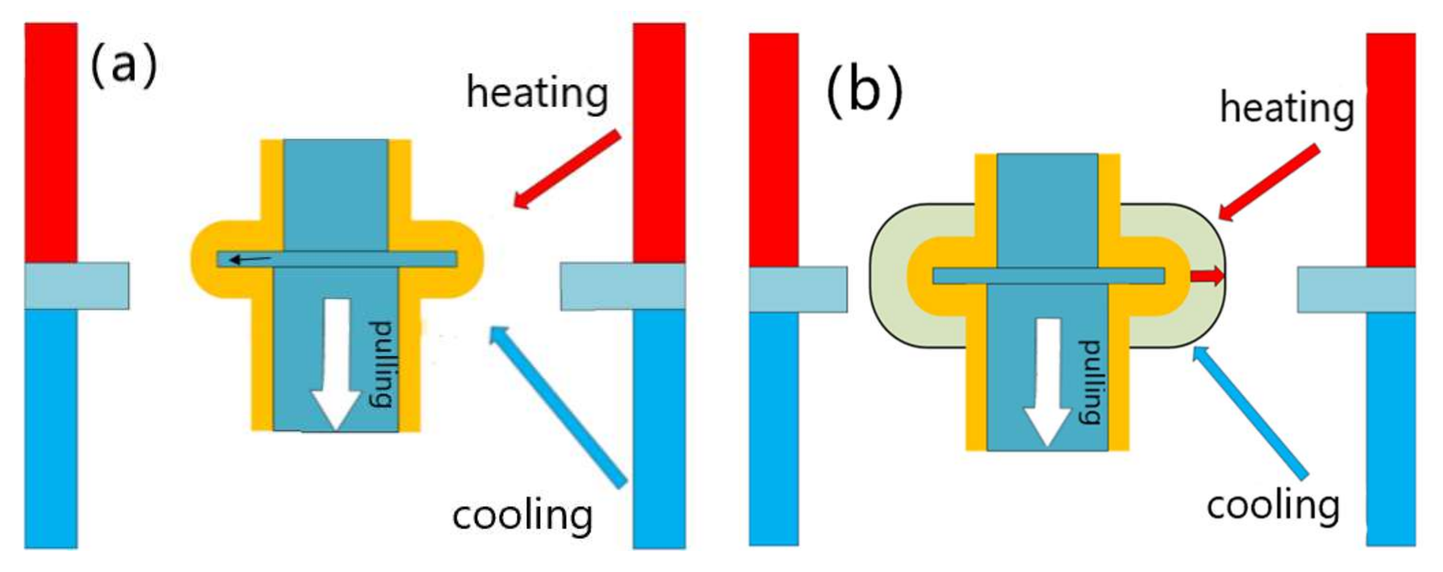
2.1. Ceramic Mold Design
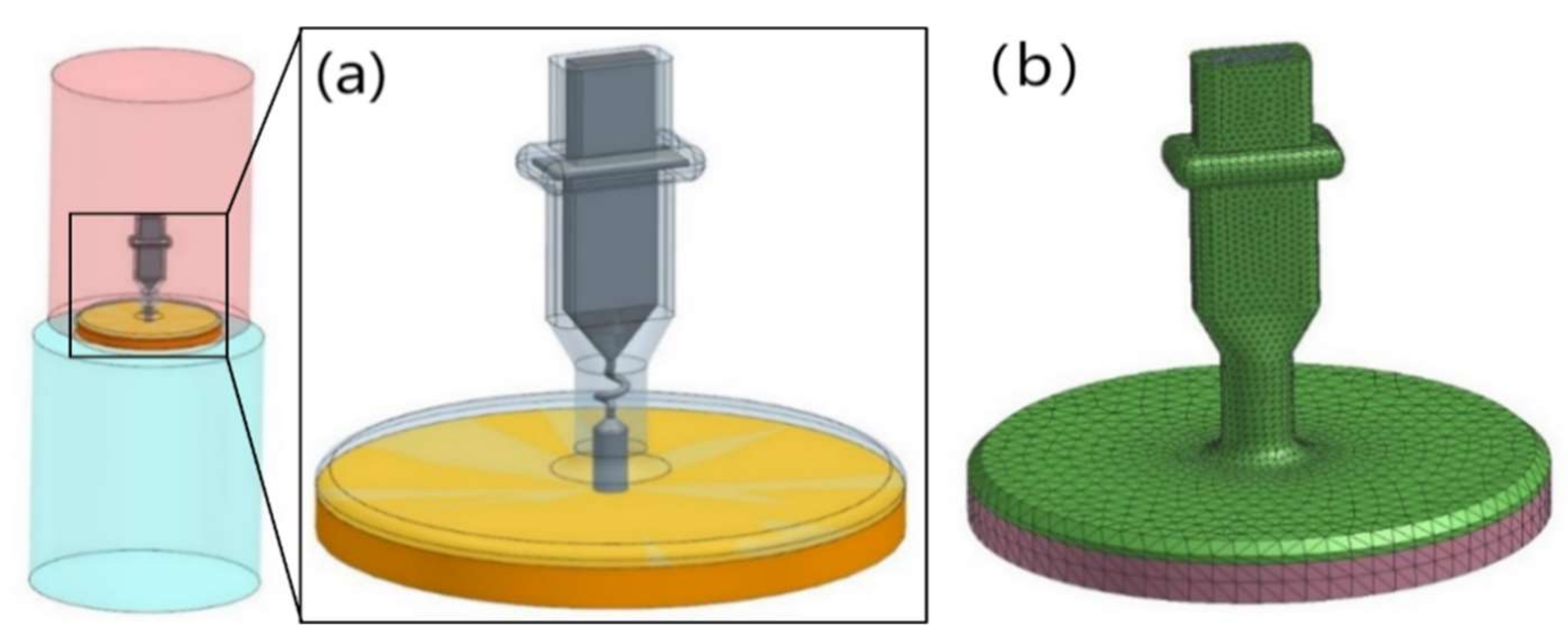
2.2. FEA Model
3. Result and Discussion
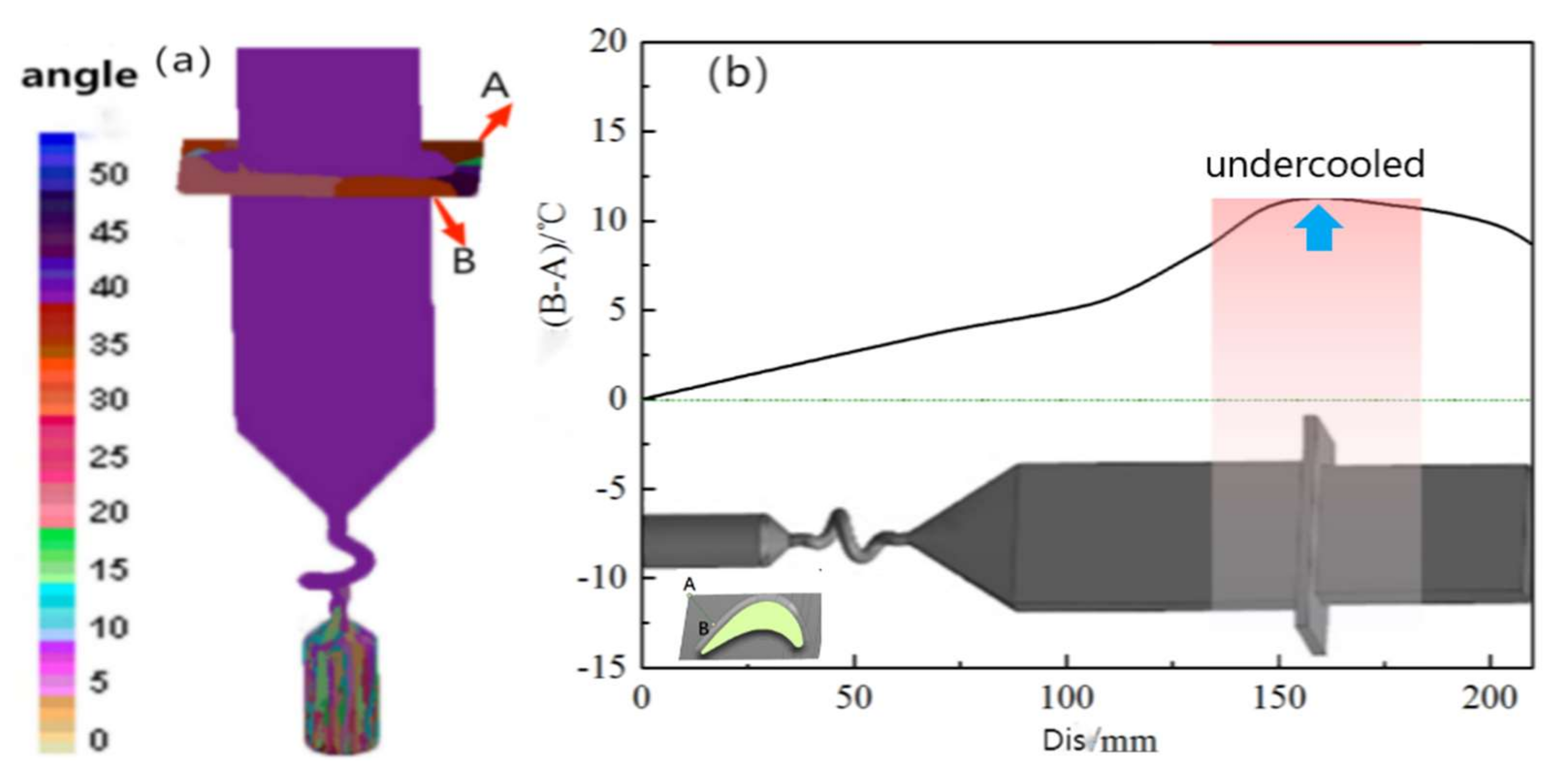
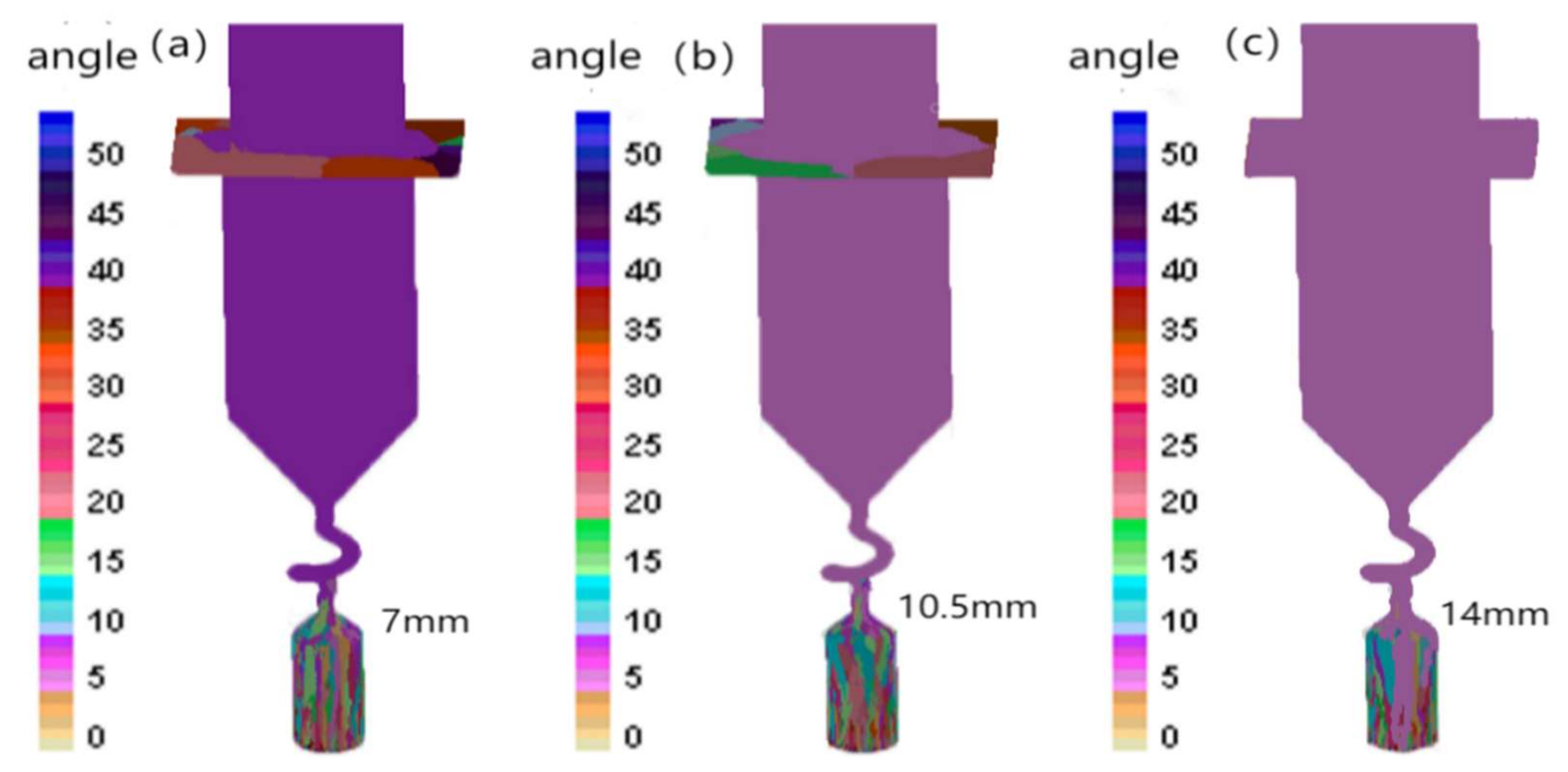
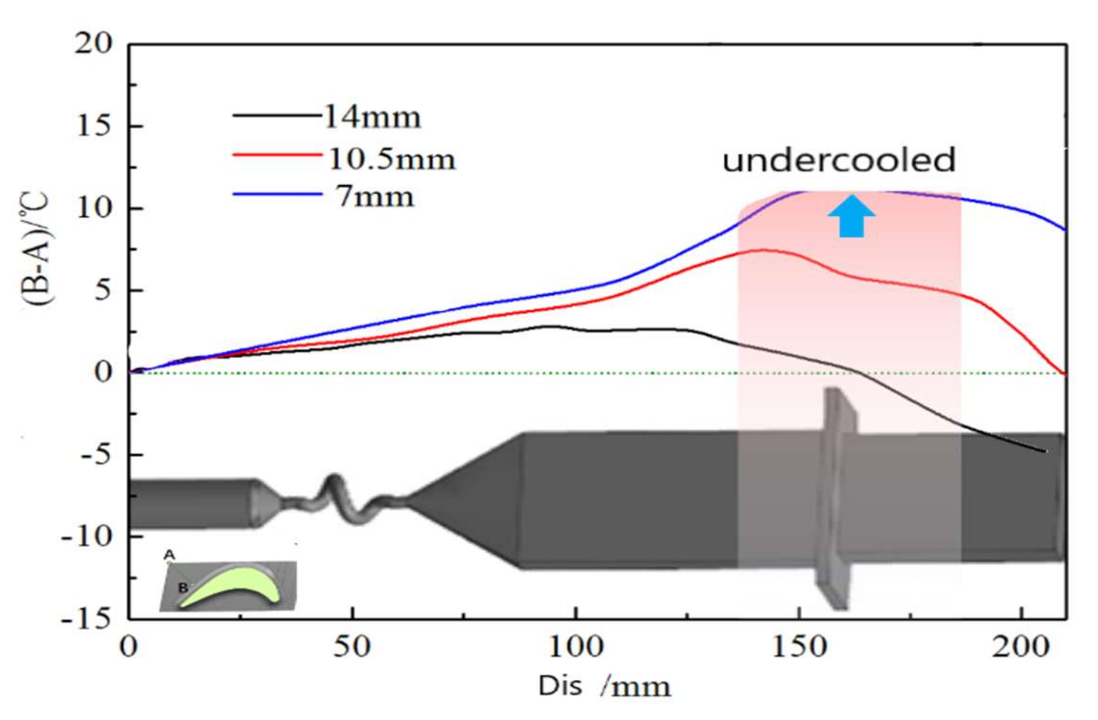
3.1. FEA Results
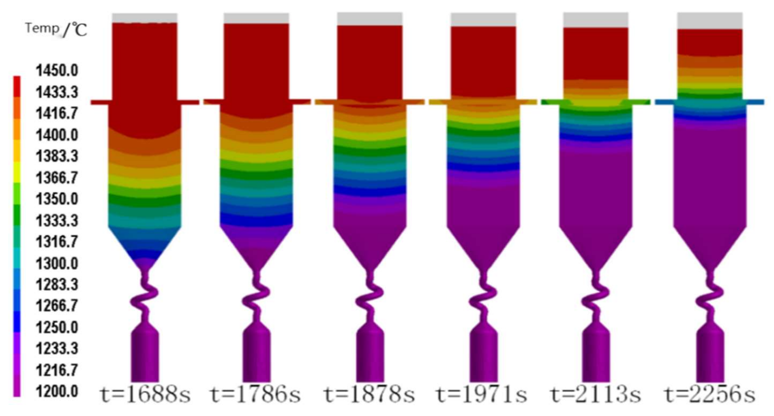
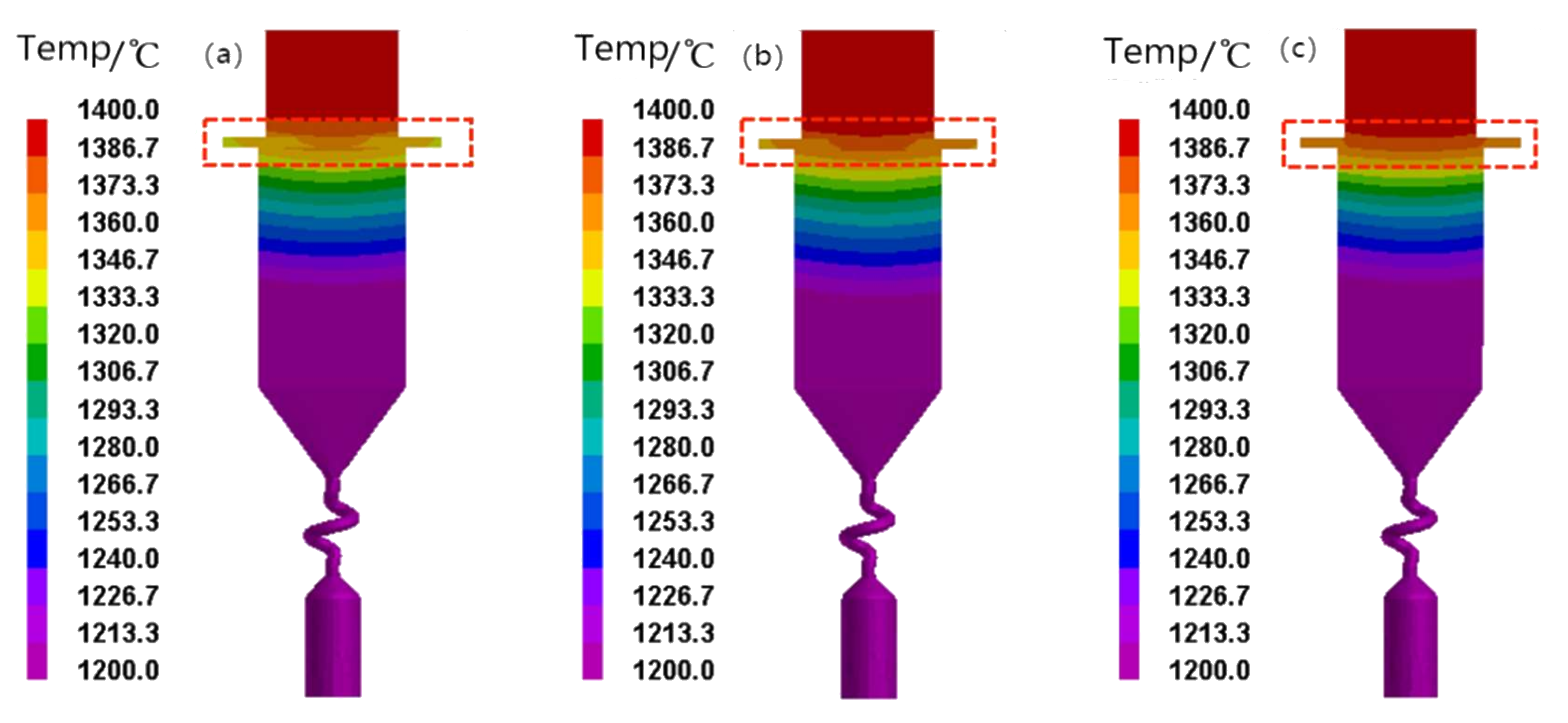
3.2. Temperature Field Analysis
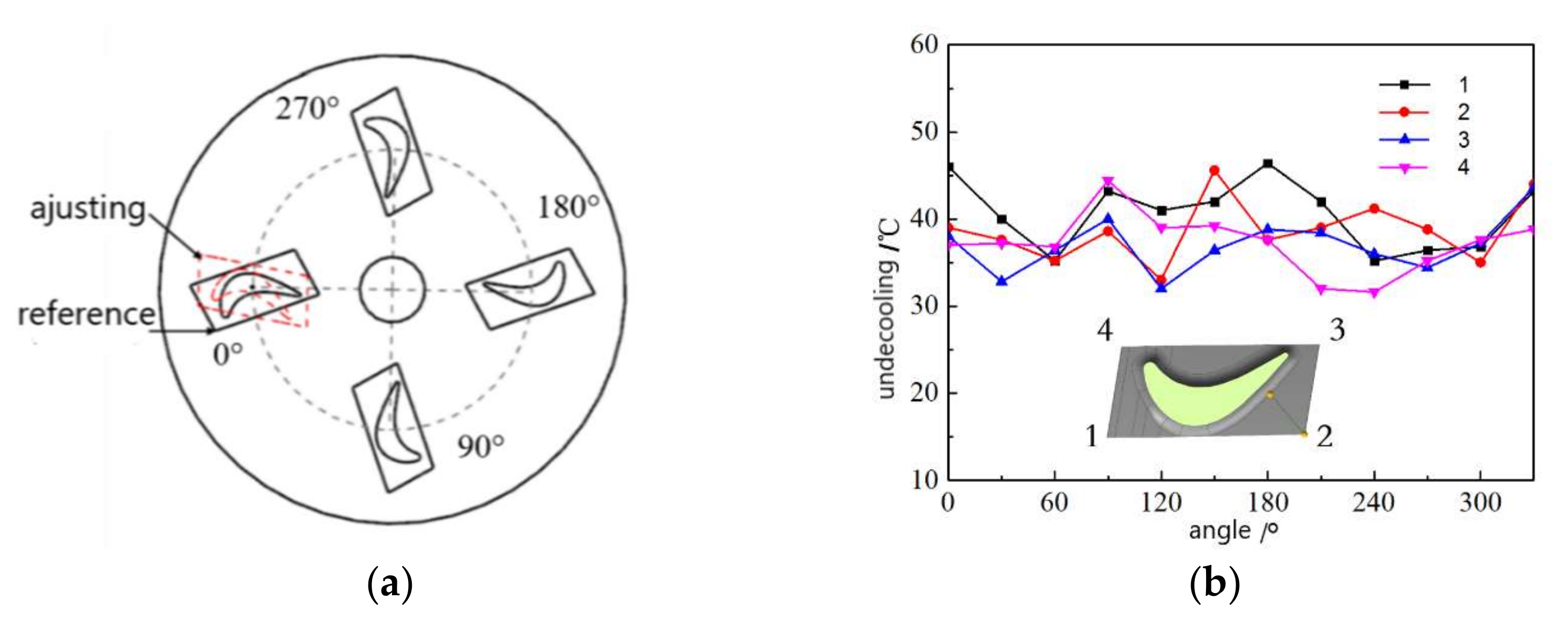
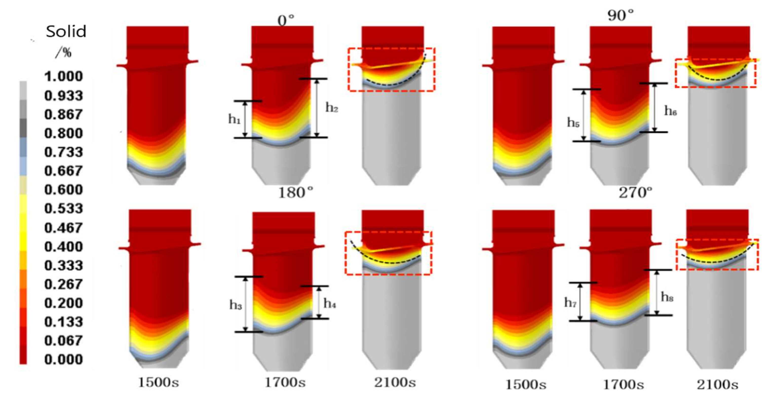
3.3. Molds Assembly Angle
4. Conclusions
- A variable wall thickness mold was manufactured based on SL and gelcasting technology, taking advantage of the flexibility of IFTCM technology. By increasing the wall thickness of the mold at the platform of the blade, the temperature field distribution during DS was improved, and the formation of the gray grains at the platform can be avoided.
- The influence of the variable wall thickness mold on the temperature field of the platform was evaluated. When the wall thickness is varied, the undercooling degree of the alloy melt at the platform can be greatly reduced during DS, thus reducing the possibility of forming stray grains. For the object studied in this paper, when the wall thickness of the mold at the platform is increased to 14 mm, the local undercooling at the platform can be completely solved and the stray grain defects are eliminated. The results of the CAFE simulation also illustrate it.
- The mold assembly angle also has an important influence on the formation of stray grains at the platform. When the blades are placed at different angles, the change of heat dissipation conditions at different parts of the mold will lead to different subcooling degrees at the platform. It is found that there is an ideal mold assembly angle around 270° when the undercooling degree at the platform is relatively small and the solid–liquid interface is relatively straight. It is helpful in eliminating stray grains.
Author Contributions
Funding
Data Availability Statement
Acknowledgments
Conflicts of Interest
References
- Fu, H.; Geng, X. High rate directional solidification and its application in single crystal superalloys. Sci. Technol. Adv. Mater. 2001, 2, 197–204. [Google Scholar] [CrossRef] [Green Version]
- Xuan, W.; Li, C.; Zhao, D.; Wang, B.; Li, C.; Ren, Z.; Zhong, Y.; Cao, G. Effect of Primary Dendrite Orientation on Stray Grain Formation in Cross-Section Change Region During the Directional Solidification of Ni-Based Superalloy. Metall. Mater. Trans. B 2016, 48, 394–405. [Google Scholar] [CrossRef]
- Xuan, W.; Liu, H.; Lan, J.; Li, C.; Zhong, Y.; Li, X.; Cao, G.; Ren, Z. Effect of a Transverse Magnetic Field on Stray Grain Formation of Ni-Based Single Crystal Superalloy during Directional Solidification. Metall. Mater. Trans. B 2016, 47, 3231–3236. [Google Scholar] [CrossRef]
- Pollock, T.M.; Tim, S. Nickel-based superalloy for advanced turbine engines: Chemistry, microstructure, and properties. J. Propul. Power 2006, 22, 361. [Google Scholar] [CrossRef]
- Reed, R.C. The Superalloy Fundamental and Applications; Cambridge University Press: Cambridge, UK, 2006; Volume 1. [Google Scholar]
- Ma, D.; Bührig-Polaczek, A. Development of Heat-Conductor Technique for SC Components of Superalloy. Int. J. Cast Met. Res. 2009, 22, 422–429. [Google Scholar] [CrossRef]
- Ma, D.; Polaczek, A.B. Application of Heat-Conductor Technique to Production of SC Turbine Blade. Metall. Mater. Trans. B 2009, 40, 738–748. [Google Scholar] [CrossRef]
- Ma, D.; Bührig-Polaczek, A. Avoiding Grain defect in Single Crystal Components by Application of a Heat Conductor Technique. Int. J. Mater. Res. 2009, 100, 1145–1151. [Google Scholar] [CrossRef]
- Meyerter Vehn, M.; Dedecke, D.; Paul, U.; Sahm, P.R. Undercooling related casting defect in SC turbine blades. Superalloys 1996, 471–479. [Google Scholar]
- Lu, Z.; Zhao, L.; Li, Y.; Wu, H.; Li, D. Thermal Behavior of Integral Al2O3-Based ceramic mold for Fabricating Gas Turbine Blades. Proc. Inst. Mech. Eng. B-J. Eng. 2014, 228, 695–703. [Google Scholar]
- Backman, D.G.; Williams, J.C. Advanced Materials for Aircraft Engine Applications. Science 1992, 255, 1082–1087. [Google Scholar]
- Wu, H.; Li, D.; Tang, Y.; Sun, B.; Cui, F.; Guo, N. Rapid Casting of Hollow Turbine Blades Using Integral Ceramic Moulds. Proc. Inst. Mech. Eng. B-J. Eng. 2009, 223, 695–702. [Google Scholar]
- Tian, G.; Lu, Z.; Miao, K.; Ji, Z.; Zhang, H.; Li, D.; Lloyd, I. Formation Mechanism of Cracks during the Freeze Drying of Gelcast Ceramic Parts. J. Am. Ceram. Soc. 2015, 98, 3338–3345. [Google Scholar] [CrossRef]
- Cai, K.; Guo, D.; Huang, Y.; Yang, J. Solid Freeform Fabrication of Alumina Ceramic Parts Through a Lost Mould Method. J. Eur. Ceram. Soc. 2003, 23, 921–925. [Google Scholar] [CrossRef]
- Wu, H.; Li, D.; Tang, Y.; Sun, B.; Xu, D. Rapid Fabrication of Aluina-Based Ceramic Cores for Gas Turbine Blades by Stereolithography and Gelcasting. J. Mater. Process. Technol. 2009, 209, 5886–5891. [Google Scholar]
- Young, A.C.; Omatete, O.O.; Janney, M.A.; Menchhofer, P.A. Gelcasting of Alumina. J. Am. Ceram. Soc. 1991, 74, 612–618. [Google Scholar] [CrossRef]
- Chapman, L.A. Application of high temperature DSC technique to nickel based superalloys. J. Mater. Sci. 2004, 39, 7229–7236. [Google Scholar] [CrossRef]
- Neuer, G. Spectral and total emissivity measurements of highly emitting materials. Int. J. Thermophys. 1995, 16, 257–265. [Google Scholar] [CrossRef]
- Carter, P.; Cox, D.C.; Gandin, C.A.; Reed, R.C. Process modelling of grain selection during the solidification of single crystal superalloy castings. Mater. Sci. Eng. A 2000, 280, 233–246. [Google Scholar] [CrossRef]
- Ma, D.; Wu, Q.; Bührig-Polaczek, A. Undercoolability of superalloy and solidification defect in single crystal components. Adv. Mater. Res. 2011, 278, 417–422. [Google Scholar] [CrossRef] [Green Version]
- Szeliga, D.; Kubiak, K.; Sieniawski, J. Control of liquidus isotherm shape during solidification of Ni-based superalloy of single crystal platforms. J. Mater. Process. Technol. 2016, 234, 18–26. [Google Scholar] [CrossRef]
- Lu, J.W.; Chen, F. Assessment of mathematical models for the flow in directional solidification. J. Cryst. Growth 1997, 171, 601–613. [Google Scholar] [CrossRef]
- Yu, J.; Xu, Q.Y.; Cui, K.; Liu, B.C.; Kimatsuka, A.; Kuroki, Y.; Hirata, A. Numerical Simulation of Solidification Process on Single Crystal Ni-Based Superalloy Investment Castings. J. Mater. Sci. Technol. 2007, 23, 47–54. [Google Scholar]
- Derby, J.J.; Gasperino, D.; Zhang, N.; Yeckel, A. Modeling the crystal growth of cadmium zinc telluride: Accomplishments and future challenges. Nucl. Radiat. Detect. Mater. MRS Proc. 2009, 1164-L05-02, 45–56. [Google Scholar] [CrossRef]
- Chen, Y.; Billia, B.; Li, D.Z.; Nguyen-Thi, H.; Xiao, N.M.; Bogno, A.-A. Tip-splitting instability and transition to seaweed growth during alloy solidification in anisotropically preferred growth direction. Acta Mater. 2014, 66, 219–231. [Google Scholar]
- Elliott, A.J.; Pollock, T.M.; Tin, S.; King, W.T.; Huang, S.-C.; Gigliotti, M.F.X. Directional solidification of large superalloy castings with radiation and liquid-metal cooling: A comparative assessment. Metall. Mater. Trans. A 2004, 35, 3221–3231. [Google Scholar] [CrossRef]


| Furnace Body | Diameter | Height |
|---|---|---|
| hot zone | 300 mm | 500 mm |
| Insulation zone | 260 mm | 30 mm |
| cool zone | 400 mm | 500 mm |
| Crystallizer | 250 mm | 30 mm |
| Composition | Cr | Mo | Co | W | Ta | Al | Ti | Hf | Re | Ni |
|---|---|---|---|---|---|---|---|---|---|---|
| Weight Fraction(wt/%) | 6.4 | 0.61 | 9.6 | 6.4 | 6.6 | 5.67 | 1.04 | 0.1 | 2.9 | 60.68 |
| Temperature (°C) | Enthalpy (kJ/kg) | Temperature (°C) | Density (kg/m3) | Temperature (°C) | Coe. of Heat Conductivity (W/mK) |
|---|---|---|---|---|---|
| c | 0 | 25 | 8700 | 100 | 8.65 |
| 201 | 74 | 100 | 8665 | 200 | 11.6 |
| 423 | 173 | 200 | 8618 | 500 | 14.9 |
| 570 | 242 | 300 | 8572 | 900 | 20 |
| 750 | 335 | 400 | 8525 | 1200 | 32 |
| 1003 | 481 | 500 | 8479 | 1380 | 25.6 |
| 1076 | 528 | 600 | 8433 | 1500 | 25.3 |
| 1129 | 566 | 700 | 8387 | 1600 | 25 |
| 1201 | 622 | 800 | 8342 | ||
| 1312 | 714 | 900 | 8296 | ||
| 1320 | 722 | 1000 | 8251 | ||
| 1332 | 732 | 1100 | 8206 | ||
| 1347 | 762 | 1200 | 8161 | ||
| 1356 | 798 | 1300 | 8116 | ||
| 1358 | 824 | 1320 | 8107 | ||
| 1367 | 861 | 1380 | 7754 | ||
| 1376 | 918 | 1400 | 7736 | ||
| 1380 | 941 | 1500 | 7646 | ||
| 1382 | 945 | 1600 | 7556 | ||
| 1419 | 963 | ||||
| 1499 | 1009 |
| Basic Simulation Parameters | Value |
|---|---|
| Hot zone temperature | 1550 °C |
| Transition zone temperature | 1000 °C |
| Cool zone temperature | 50 °C |
| Crystallizer temperature | 50 °C |
| Thermal radiation coefficient (Hot and cool zone) | 0.8 [18] |
| Thermal radiation coefficient (Transition zone) | 0.8 [18] |
| Thermal radiation coefficient (Shell mold) | 0.7 |
| Heat transfer coefficient (Water-cooled ring/metal) | 2000 W/(m2·K) [19] |
| Heat transfer coefficient (Mold/metal) | 500 W/(m2·K) [19] |
| Heat transfer coefficient (Water-cooled ring/mold) | 20 W/(m2·K) [19] |
Publisher’s Note: MDPI stays neutral with regard to jurisdictional claims in published maps and institutional affiliations. |
© 2022 by the authors. Licensee MDPI, Basel, Switzerland. This article is an open access article distributed under the terms and conditions of the Creative Commons Attribution (CC BY) license (https://creativecommons.org/licenses/by/4.0/).
Share and Cite
Liu, Z.; Miao, K.; Lian, W.; Lu, Z.; Li, D. Elimination of the Stray Grain Defects of Single Crystal Blade by Variable Wall Thickness Based on Integral Ceramic Mold. Metals 2022, 12, 1832. https://doi.org/10.3390/met12111832
Liu Z, Miao K, Lian W, Lu Z, Li D. Elimination of the Stray Grain Defects of Single Crystal Blade by Variable Wall Thickness Based on Integral Ceramic Mold. Metals. 2022; 12(11):1832. https://doi.org/10.3390/met12111832
Chicago/Turabian StyleLiu, Zhefeng, Kai Miao, Weibo Lian, Zhongliang Lu, and Dichen Li. 2022. "Elimination of the Stray Grain Defects of Single Crystal Blade by Variable Wall Thickness Based on Integral Ceramic Mold" Metals 12, no. 11: 1832. https://doi.org/10.3390/met12111832