Article

Microstructure Comparison for AlSn20Cu Antifriction Alloys Prepared by Semi-Continuous Casting, Semi-Solid Die Casting, and Spray Forming

1
State Key Laboratory of Nonferrous Metals and Processes, GRINM Group Co., Ltd., Beijing 100088, China
2
GRIMAT Engineering Institute Co., Ltd., Beijing 101407, China
*
Author to whom correspondence should be addressed.
Metals 2022, 12(10), 1552; https://doi.org/10.3390/met12101552
Submission received: 10 August 2022 / Revised: 28 August 2022 / Accepted: 10 September 2022 / Published: 20 September 2022
(This article belongs to the Special Issue Casting and Forming of Light Alloys)

Abstract

:
Antifriction alloys such as AlSn20Cu are key material options for sliding bearings used in machinery. Uniform distribution and a near-equiaxed granularity tin phase are generally considered to be ideal characteristics of an AlSn20Cu antifriction alloy, although these properties vary by fabrication method. In this study, to analyze the variation of the microstructure with the fabrication method, AlSn20Cu alloys are prepared by three methods: semi-continuous casting, semi-solid die casting, and spray forming. Bearing blanks are subsequently prepared from the fabricated alloys using different processes. Morphological information, such as the total area ratio and average particle diameter of the tin phase, are quantitatively characterized. For the tin phase of the AlSn20Cu alloy, the deformation and annealing involved in semi-continuous casting leads to a prolate particle shape. The average particle diameter of the tin phase is 12.6 µm, and the overall distribution state is related to the deformation direction. The tin phase of AlSn20Cu alloys prepared by semi-solid die casting presents both nearly spherical and strip shapes, with an average particle diameter of 9.6 µm. The tin phase of AlSn20Cu alloys prepared by spray forming and blocking hot extrusion presents a nearly equilateral shape, with an average particle diameter of 6.2 µm. These results indicate that, of the three preparation methods analyzed in this study, semi-solid die casting provides the shortest process flow time, whereas a finer and more uniform tin-phase structure may be obtained using the spray-forming process. The semi-solid die casting method presents the greatest potential for industrial application, and this method therefore presents a promising possibility for further optimization.

1. Introduction

Sliding bearings are key components that are commonly used in machinery; antifriction alloys are the main materials employed in their manufacture. Bearing antifriction alloy materials generally have two metallographic structures. The first type of structure is based on a soft-phase matrix, where the hard phase is evenly distributed in the form of particles, such as in tin- and lead-based alloys. The second type of structure is based on a hard-phase matrix, where the soft phase is uniformly distributed in the form of particles, such as in aluminum–tin alloys and copper–lead alloys [1,2]. The Babbitt alloy belongs to the first type of antifriction alloy. It exhibits good compliance, compatibility, and embedment with other materials, although it has poor bearing capacity and heat resistance. It is prone to sticking and corrosion because of its lead content. The Babbitt alloy is therefore suitable for use under stable load working conditions, but not for use under heavy load conditions, and has been gradually phased out of industrial production. The second type of antifriction alloy for preparing self-lubricant bearings presents significant advantages. During working, the hard matrix structure of the bearing ensures that the bearing bush is not deformed, whereas the soft phase is easily worn out, forming a gap between the bearing bush and the bearing that contains the lubricant. As a representative example of the second type of antifriction alloy, aluminum–tin and copper–lead alloys are widely used in high-load mechanisms. However, preparation of this second type of antifriction alloy is more difficult than that of the first, where the main difficulty is related to controlling the distribution morphology of the soft phase in the matrix. For aluminum–tin alloys, the tin-phase morphology in the alloy is one of the most critical technical indicators for potential applications, and the fine, uniform, and nearly equiaxed Sn phase is the ideal application state for alloys [3,4,5].
Semi-continuous casting of aluminum–tin alloy ingots, followed by processing the aluminum–tin alloy bearing blanks through multiple deformations and annealing, is presently the most commonly used process. The morphology of the tin phase of alloys prepared in this manner is affected by the deformation, and the phase forms a flat strip along the deformation direction. Annealing treatments above the melting point of tin are used to obtain a granular tin phase, which causes tin liquefaction and overflow from the matrix [6,7,8,9,10]. Aluminum–tin alloys can be prepared by powder metallurgy [11,12,13,14,15]. However, this process is extremely complicated, involving multiple processes such as powder milling, powder mixing, wrapping, degassing, and sintering. In addition, if the sintering temperature is higher than the melting point of the tin phase (232 °C), the tin phase becomes reticular and segregates. However, if the sintering temperature is lower than the melting point of the tin phase, the aluminum matrix is not able to metallurgically bond. Although there are many reports on the preparation of aluminum alloys by spray forming, few studies describe aluminum–tin alloy preparation by spray forming, although these studies [16,17,18,19] confirmed the feasibility of preparing Al-Sn alloys using this approach. However, because spray forming involves the use of high-speed airflow as the driving force for deposition and forming, defects are inevitably introduced; few studies have considered the analysis and elimination of these defects. In contrast, the preparation of aluminum alloys by semi-solid die casting is a mature technology [20,21,22], although there have been no studies describing the preparation of aluminum–tin alloys by semi-solid die casting.
In this study, three methods: semi-continuous casting, semi-solid die casting, and spray forming are used to prepare aluminum–tin alloy billets for analyzing the variation of microstructure with fabrication method. Different processes are used for the subsequent processing (except semi-solid die casting) to obtain self-lubricating and antifriction bearing bush blanks. The microstructures of the materials obtained by these three processes are compared, providing valuable data that may be used in the improvement of aluminum–tin alloy processing technologies. This study also provides a meaningful experimental reference for the preparation of alloys such as copper–lead alloys, in which a low-melting-point phase is uniformly distributed in a high-melting-point matrix.

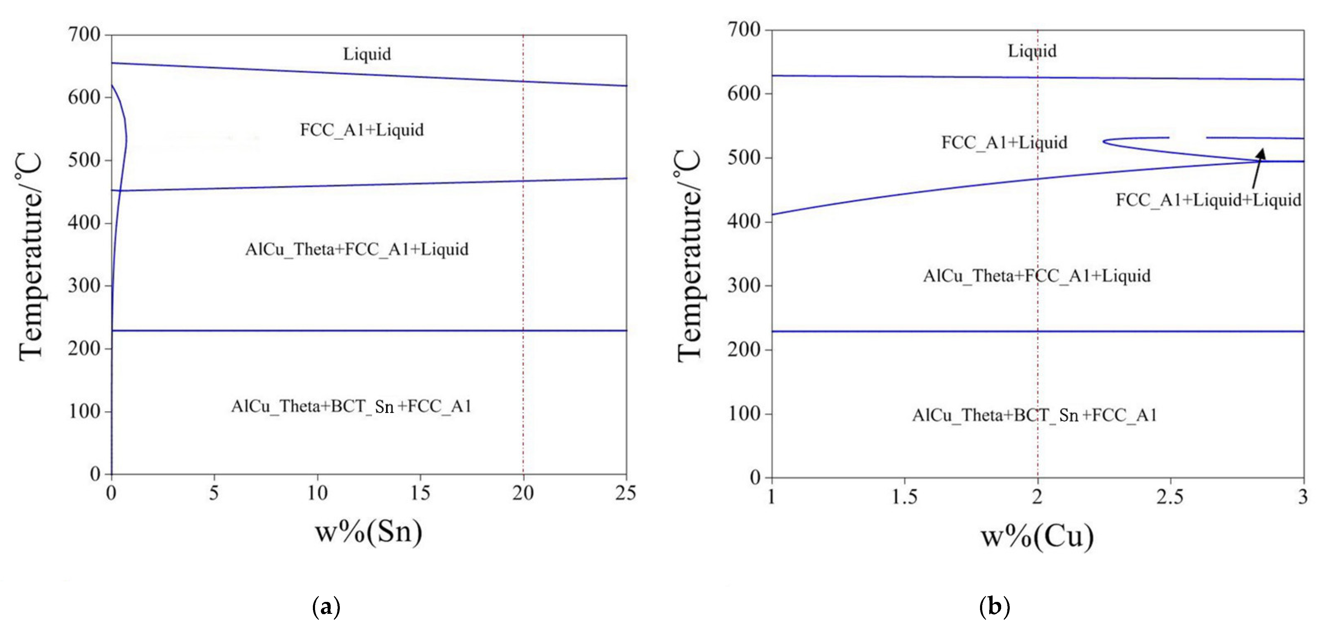
2. Materials and Methods

The composition of the alloy prepared in this experiment is 20.0 wt.% Sn, 2.0 wt.% Cu, with the remainder of the material comprising Al. The purity of all raw materials is above 99.9%. The software PANDAT (CompuTherm LLC, Middleton, WI, USA) was used to calculate the equilibrium phase diagram of the AlSn20Cu alloy and the results are shown in Figure 1. Figure 1a shows the phase transition with increasing Sn content in Al–2Cu matrix, and Figure 1b shows the phase transition with increasing Cu content in Al–20Sn matrix. Tin and aluminum cannot dissolve each other in the solid state, they both maintain the original phase structure. Copper is present in the aluminum matrix (FCC_Al) in the form of Al2Cu (AlCu_Theta).
Spray forming is conducted using SF-500 equipment (GRIMAT Ltd., Beijing, China), which is a self-made machine. The schematic diagram of SF-500 equipment for spray forming is shown in Figure 2. Semi-continuous casting and semi-solid die casting was conducted using universal equipment. A metallographic microscope and scanning electron microscope (SEM) are used to observe the microstructures of the alloys. Image processing software (ImageJ software, National Institutes of Health & Laboratory for Optical and Computational Instrumentation, Madison, WI, USA) is used to analyze the morphology of the Sn phase.
The AlSnCu alloy ingot prepared by semi-continuous casting is cylindrical, which needs to be rolled and heat treated to form the plate for making the bearing bush. Gleeble compression experiments were used to study the process parameters of rolling deformation. The compression experiment temperature is 20, 100, 150, 202, 222, and 242 °C; the strain rate is 0.01, 0.1, and 1 s−1; the deformation is 60%; and the quenching and cooling are realized within 3 s after deformation. The AlSnCu alloy ingot prepared by semi-solid die casting is flat, which reduces the production process of the bearing bush. The AlSnCu alloy ingots prepared by spray forming are also cylindrical. Because there are many defects in it, it needs to be reduced by densification process, and finally the ingot is sliced into plates.

3. Results

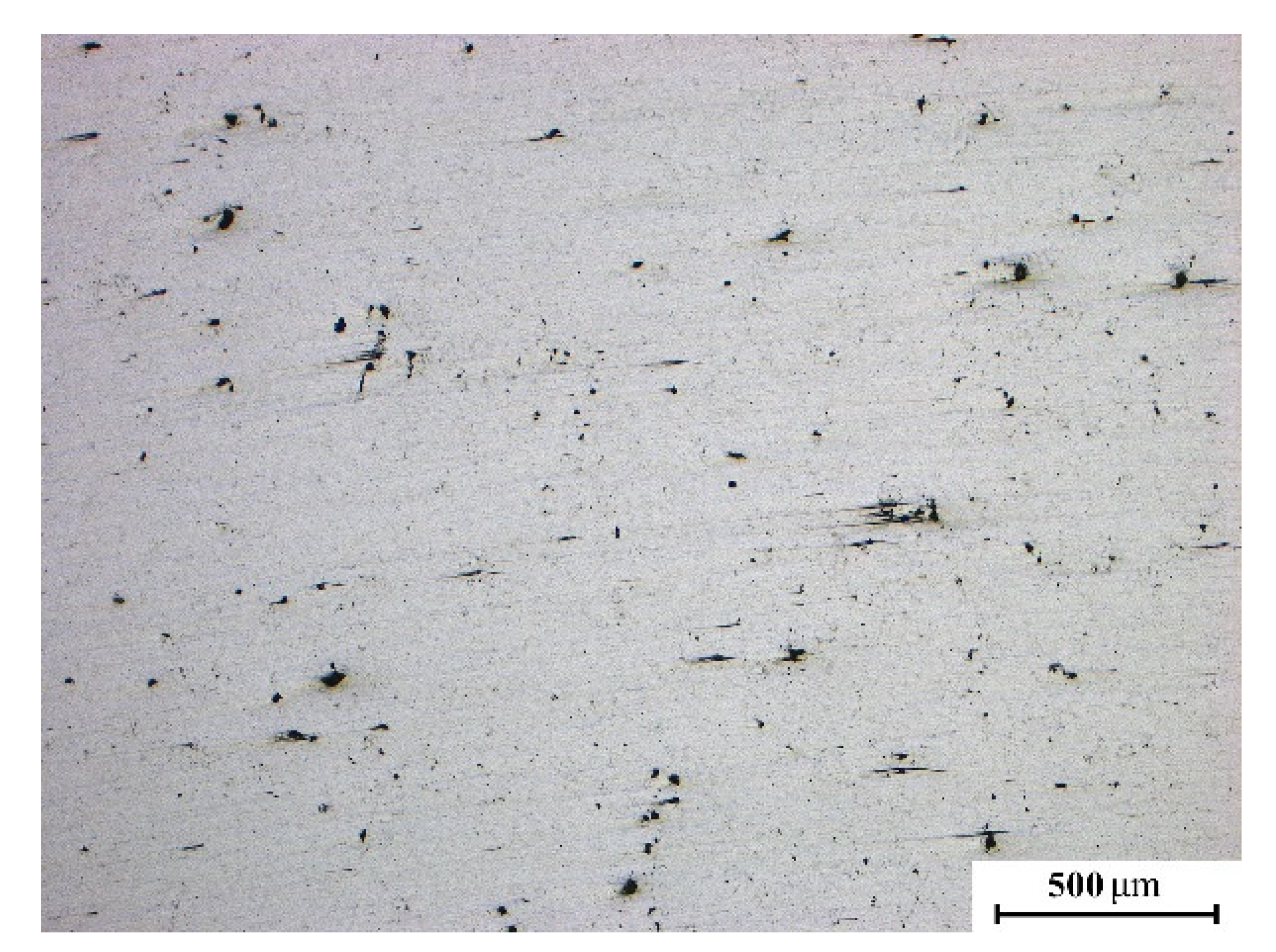
3.1. Semi-Continuous Casting

The process and ingot of an AlSn20Cu alloy prepared by semi-continuous casting is shown in Figure 3, for which the ingot diameter is Ф150 mm. The metallographic and SEM photos of the semi-continuously cast AlSn20Cu alloy are shown in Figure 4. There are some porosity casting defects in the ingot. In addition to the tin phase that is distributed at the grain boundaries of the aluminum matrix, there are also granular tin phases inside the grains. Thus, the tin phase is distributed in a network in the aluminum matrix, resulting in poor deformation properties of the alloy.
Figure 5 shows the EDS analysis of semi-continuous casting AlSnCu alloy, and the order corresponds to the points marked in Figure 4b. From the results of EDS analysis, it can be seen that the matrix is mainly composed of aluminum, and a small amount of copper is solid solution in the matrix. The brightest phase is tin, and a small amount of gray phase is Al2Cu. Subsequently, the phase of the alloy was analyzed by XRD, and the results are shown in Figure 6. XRD analysis can only see the diffraction characteristics of Al and Sn, but not the diffraction information of Al2Cu. This also shows that the amount of Al2Cu is very small, so in the subsequent quantitative analysis of the phase, the Al2Cu phase can be ignored.
The deformation properties of AlSn20Cu are studied using a Gleeble compression experiment. Macro-photographs of the post-compression test are shown in Figure 7.
When subject to deformation above the Sn melting point (232 °C), the Sn phase melts and is extruded from the matrix. Deformation below the melting point of the Sn phase results in a smooth sample surface. However, when deformation is too fast, deformation heat causes an increase in sample temperature, resulting in melting of the Sn phase. In this experiment, Sn phase melting occurs when deformation is conducted at a temperature and strain rate of 222 °C and 1 s−1, respectively.
When the deformation temperature is below 150 °C, the alloy will crack, even at an extremely low deformation rate. In Figure 7, the red boxes mark samples with cracking, the blue boxes mark samples with tin-phase spillage, and the green boxes mark samples with neither cracking nor tin-phase spillage. Therefore, the blocking hot extrusion process will be conducted at a strain rate of 0.01–0.1 s−1 between 202 and 222 °C.
Figure 8 shows photos of the preparation of an antifriction bearing bush blank using a semi-continuous cast AlSn20Cu alloy. Figure 8a,b indicates a hot rolled billet at 210 °C for the first time and second time, respectively. Coating was applied to the surface of the sheet to prevent tin spillage, and the sheet was annealed at 250 °C for 10 h (Figure 8c). Figure 8d shows the final milled sheet after rolling.
The antifriction bearing bush blank is prepared by two hot rolling processes, one heat treatment and one cold rolling process. Its microstructure is shown in Figure 9. The initial network morphology of the tin phase is destroyed and transformed into a granular form. The particle shape shows directionality and is stretched along the deformation direction.

3.2. Semi-Solid Die Casting
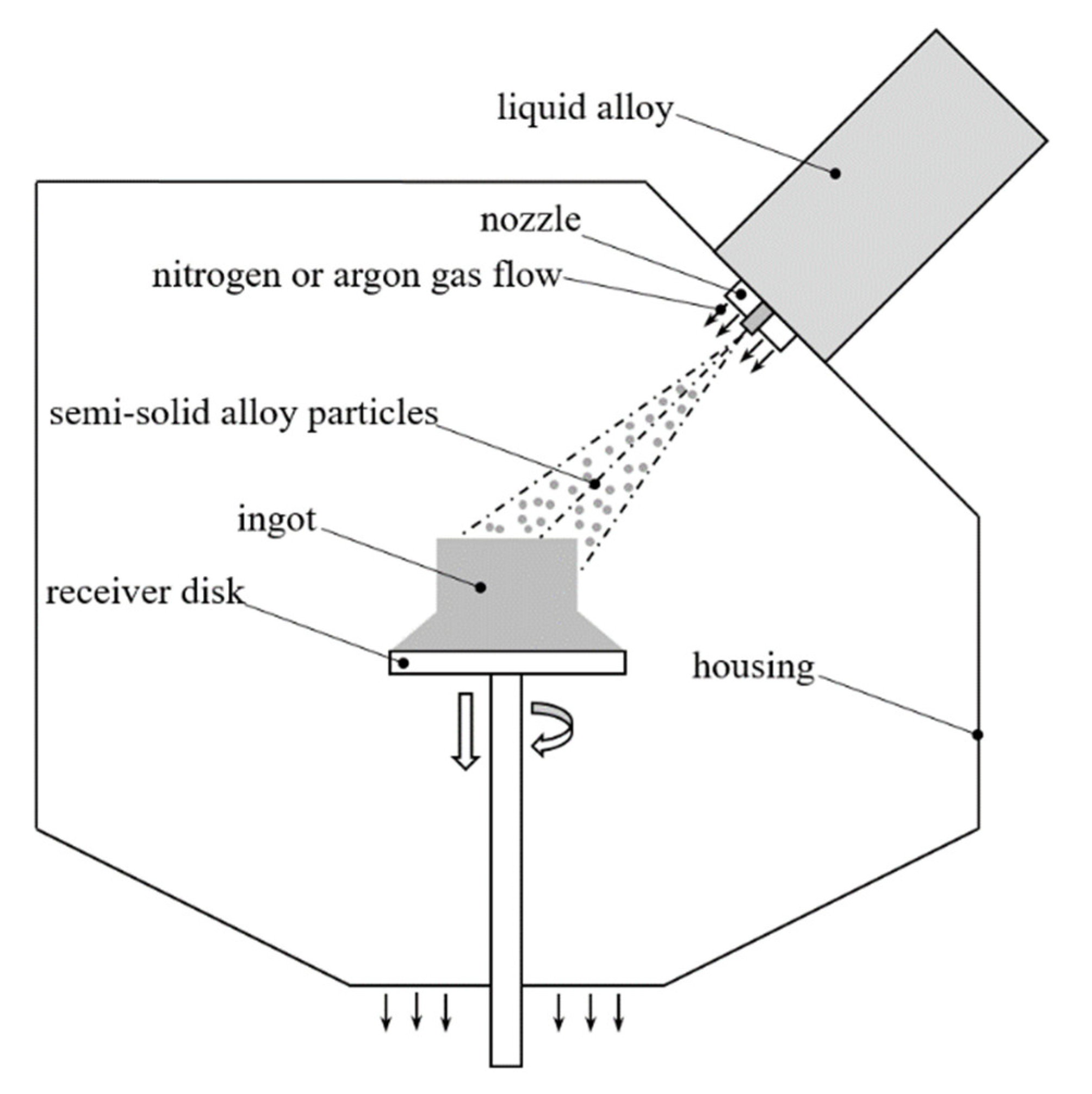
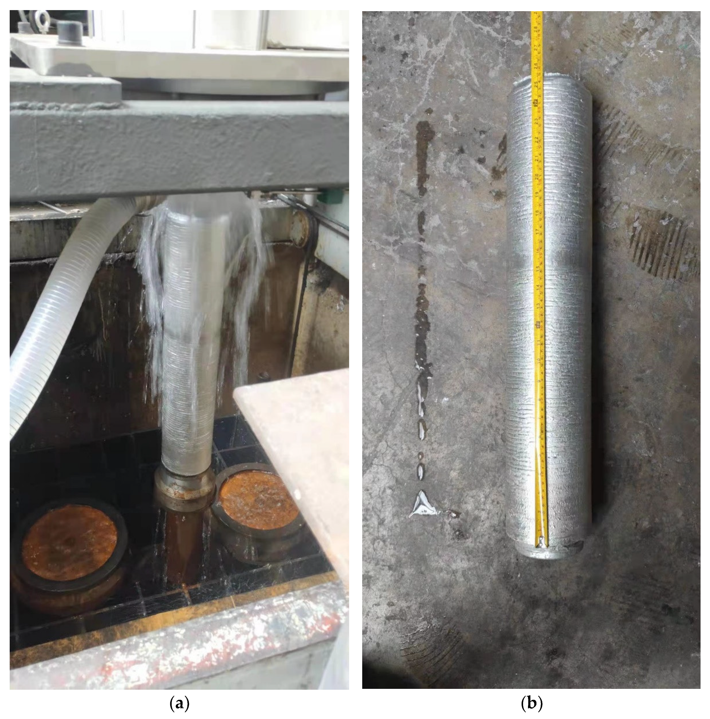
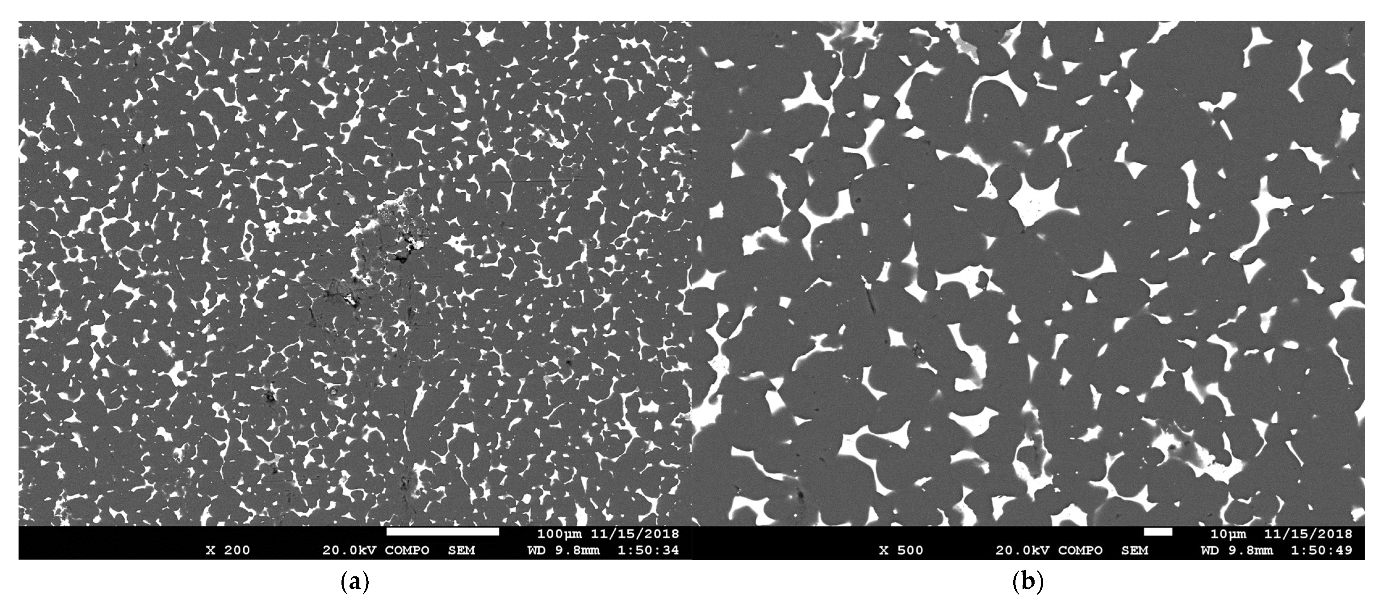
According to the Al-Sn-Cu phase diagram in Figure 1, the temperature of the AlSn20Cu alloy solution is adjusted to approximately 720 °C. It is then transferred to a mechanical vibration platform. Under the action of mechanical vibration and stirring, when the alloy solution drops to 610 ± 5 °C, it is transferred to the die casting machine, for which the speed of the in-mold gate is fixed at approximately 40 m/s. Figure 10 shows the semi-solid die casting billet; its corresponding SEM image is shown in Figure 11. Compared with that produced using semi-continuous casting, the AlSn20Cu alloy prepared by semi-solid die casting does not require deformation and annealing, and a granular tin phase may be obtained. No defects are observed in the ingot, although some tin phases are observed in strips along the grain boundaries of the aluminum matrix.

3.3. Spray Forming

The alloy ingot with an outer contour size of Φ190 mm × 500 mm prepared by spray forming is shown in Figure 12. Figure 13 shows a metallographic photo of the ingot produced using spray forming. It can be observed that, compared with the other ingot making processes, the number of defects in the ingot prepared by spray forming is larger, but the defect size is significantly smaller than that of ordinary casting. Figure 14 shows an SEM image of the ingot produced using spray forming.
High-speed ejected nitrogen or argon is used to drag the metal droplets towards the receiver desk during the spray-forming process, and the metal droplets rapidly cool during flight to form semi-solid particles, which are superimposed and deposited into the ingot. The particles inevitably entrain gases during the deposition process, and these gas particles cause defects in the ingot. The hot isostatic pressing densification process often used in powder metallurgy is not suitable for the elimination of gas-containing defects in spray-formed ingots, and the schematic diagram is shown in Figure 15. During hot isostatic pressing, the ingot is completely immersed in high pressure gas. The ingot is subjected to the same gas pressure in all directions, so the load applied by the hot isostatic pressing process only contains the spherical tensor of the stress. Under the action of the spherical tensor of stress, gas-containing defects can be compressed but not discharged. As mentioned earlier, large plastic deformation processing such as rolling may be used to eliminate defects in the original ingot, but this will also significantly change the shape of the tin phase, thereby destroying the equilateral granular tin in the original structure. To eliminate gas without introducing large deformation to change the morphology of the tin phase, a densification method by hot extrusion is proposed in this study, as shown in Figure 16. Figure 17 shows the effects of traditional hot isostatic pressing and blocking hot extrusion on gas-containing defects. The load applied by the blocking hot extrusion process includes not only the stress ball tensor but also the stress deviator tensor. The gas is squeezed out of the defect and the defect is bridged. In blocking hot extrusion, the densification of the billet may be achieved with a small macroscopic deformation resulting from the small diameter of the extrusion barrel that limits the size of the billet.
The original diameter of the extrusion billet is Φ175 mm, with an extrusion cylinder diameter of Φ180 mm. Graphite lubricant is applied to the surface to reduce friction and enhance the flow capacity of the material. The extrusion is conducted using a 1250 ton extruder. According to the Gleeble compression experiment results, the billet and extrusion cylinder are heated to 215 ± 5 °C. The ingot is continuously pressed three times using a load of more than 1000 tons. The billet is analyzed after blocking hot extrusion, as shown in the SEM images in Figure 18. No defects are found in the secondary electron images, and the Sn phase morphology in the backscattered electron images shows nearly equilateral granular morphology.

4. Discussion

Cu exists in the AlSn20Cu alloy aluminum matrix as a solid solution element, and Sn is mostly insoluble in aluminum. The discontinuous distribution of the tin phase in the grain boundaries of the aluminum matrix results in poor plasticity of the alloy. As mentioned in Section 1, aluminum–tin antifriction alloys generally require a tin-phase morphology that is in the form of nearly equilateral particles. Because of the weak deformation capacity of the alloy, the acquisition of nearly uniformly distributed equilateral granular tin phase is the main focus of this study. According to engineering practice experience and the literature [5,18], the ideal distribution of the tin phase in an AlSn20Cu alloy in terms of bearing preparation is shown in Figure 19. The tin phase is uniformly distributed in a spherical shape in a matrix that comprises the aluminum alloy.
The densities of aluminum, tin, and copper are 2.70, 7.31, and 8.96 g/cm3, respectively. Assuming that there is no volume change before and after the formation of a solid solution of aluminum and copper, the area fraction of the Sn phase in the cross-section of the AlSn20Cu alloy may be calculated as follows.
MAl:MSn:MCu = 0.78:0.2:2
MAl:MSn:MCu = (ρV)Al:(ρV)Sn:(ρV)Cu ⇒ VAl:VSn:VCu = 0.907:0.086:0.007
V1/3∝S1/2 ⇒ SAl:SSn:SCu = 0.803:0.166:0.031
where M, V, and ρ are mass, volume and density of the elements in AlSn20Cu alloy, and S is area of the elements in a section. On the premise that the weight ratio of each element in the alloy is known, according to the density of each element, the volume fraction occupied by them can be calculated. In any section of the alloy block, it is obvious that the square root of the area occupied by each element is proportional to the cube root of the volume occupied by each element in the block. According to these calculations, the area fraction occupied by the tin phase in the microstructure section of the ideal-state AlSn20Cu should be 16.6%.
The final microstructures of the AlSn20Cu alloys prepared using the three different processes are shown in Figure 4, Figure 9, Figure 11, Figure 14 and Figure 18. The same raw material is used in each process. The morphology of the Sn phase is quantitatively analyzed using image processing software, as shown in Table 1. The area fraction, particle size, and number density of tin-phase particles are analyzed, and the data in Table 1 are converted from pixel data.
The spray-forming process provides the highest ingot Sn content, and the Sn content area fraction of its cross-section reaches 13.6%, which is close to the ideal value of 16.6%. Semi-solid die casting provides the lowest ingot Sn content, at only 9.2%. The tin content in the aluminum alloy matrix is positively correlated with the cooling rate, and the faster the cooling rate, the higher is the tin content in the alloy. The smallest tin phase is observed in the ingot prepared by spray forming, with an average particle diameter of 6.5 µm. The tin phase in the ingot prepared by semi-continuous casting is the coarsest, with an average particle diameter of 13.1 µm. The agitation and vibration in the semi-solid die casting process have significant effects on the refinement of the tin phase.
After semi-continuous casting, rolling deformation and annealing, a large amount of tin is lost, and the area fraction of Sn content in the cross-section decreases from 11.4 to 8.2%. After spray forming and hot extrusion, there is no significant change in tin content and morphology. A large amount of tin in the ingot prepared by semi-solid die casting is left in the final solidified cylindrical biscuit, which essentially corresponds to the macro-segregation of tin.
According to the Al-Sn-Cu pseudo-binary partial phase diagram (Figure 1), the aluminum–tin alloy first forms Al dendrites below 660 °C during the solidification process. When cooled below 232 °C, the Sn phase gradually solidifies along the grain boundaries of the aluminum dendrites, thereby forming an as-cast network structure. The cooling rate of semi-continuous casting is of the order of 10 K/s, although the Sn phase is still distributed in a network shape along the grain boundaries of the Al matrix. After multiple deformations and annealing treatments, granular Sn that is uniformly distributed in the aluminum matrix may be obtained, and the average particle diameter of the Sn phase reaches approximately 12.6 µm. The annealing temperature must be above the melting point of the Sn phase. After the Sn phase is liquefied, the individual particles tend to be spherical under the action of surface tension. During the annealing process, after the Sn phase on the surface of the billet is liquefied, it will inevitably overflow, which results in an uneven distribution of the tin phase and a waste of materials.
The cooling rate of semi-solid die casting is similar to that of semi-continuous casting, which is in the order of 10 K/s. However, the vibration stirring and high-speed filling employed in the semi-solid die casting process have a crushing effect on the dendrites of the aluminum matrix. When the temperature of the alloy solution is lowered to approximately 610 °C under the conditions of vibration and stirring, the dendrites formed by the aluminum matrix are continuously broken and tend to be granular; the solidified aluminum reaches more than half of the total content. This is then injected into the mold cavity by pressure. The semi-solid alloy is rapidly cooled below the melting point of the tin phase, and the alloy is completely solidified. The AlSn20Cu alloy prepared by semi-solid die casting has both the characteristics of a network and granular shape. If active cooling can be introduced through appropriate design of the mold structure and the cooling rate after alloy injection can be increased, a more equilateral tin-phase granular microstructure can be obtained.
High-speed ejected nitrogen or argon is used as a power to drag the metal droplets during the spray-forming process, and the cooling speed may reach the order of 103 k/s. High-velocity airflow not only disperses the droplets, but also prompts their rapid cooling, changing the solidification process from both a thermal and mechanical perspective. The dispersed droplets have a particle size of approximately 30–50 µm, and are rapidly cooled from 720 °C until solidified. The aluminum matrix is gradually deposited and solidifies before forming dendrites, whereas the tin phase also rapidly solidifies. The Sn phase of the spray-formed ingot is in the shape of polygonal particles, with an average particle diameter of 6.5 µm. There are certain porosity defects in the ingot, but the gas may be discharged through the blocking extrusion, thereby eliminating the defects. One characteristic of the blocking extrusion process is that the densification of the material is achieved with less deformation, which implies that the morphology of the Sn phase does not significantly change after the densification process.
The initial shape of the Sn phase is determined by both thermal and mechanical factors during preparation. Different cooling rates and external force conditions cause significant differences in the tin-phase morphology of the AlSn20Cu alloys prepared by the three processes used in this study. Compared to semi-continuous casting and semi-solid die casting, the alloy cools faster during spray forming, in which the high-speed airflow suppresses and destroys aluminum dendrites. Although the cooling rate of semi-solid die casting is similar to that of semi-continuous casting, the destruction of dendrites by the vibration and stirring process prevents the tin phase from exhibiting a network-like distribution.
The study at this stage mainly focuses on the influence of the preparation process on tin phase morphology in AlSn20Cu alloys, and their wear-reducing properties are only qualitatively predicted based on tin phase morphology. The authors will carry out the wear reduction experiments of AlSn20Cu alloys prepared by three processes in the following work, and illustrate the effect of the tin phase morphology on the wear reduction performance of the alloys with specific experimental data.

5. Conclusions

(1)
For the AlSn20Cu alloy prepared by semi-continuous casting, the majority of the tin phase is distributed in a network along the grain boundaries of the aluminum matrix. After deformation and annealing treatment, the tin-phase morphology changes from that of a network to prolate particles. The average particle diameter and total area ratio of the tin phase are 12.6 µm and 8.2%, respectively. Although the annealing process results in a granular tin phase, it also leads to a situation in which the tin phase overflows from the aluminum matrix.
(2)
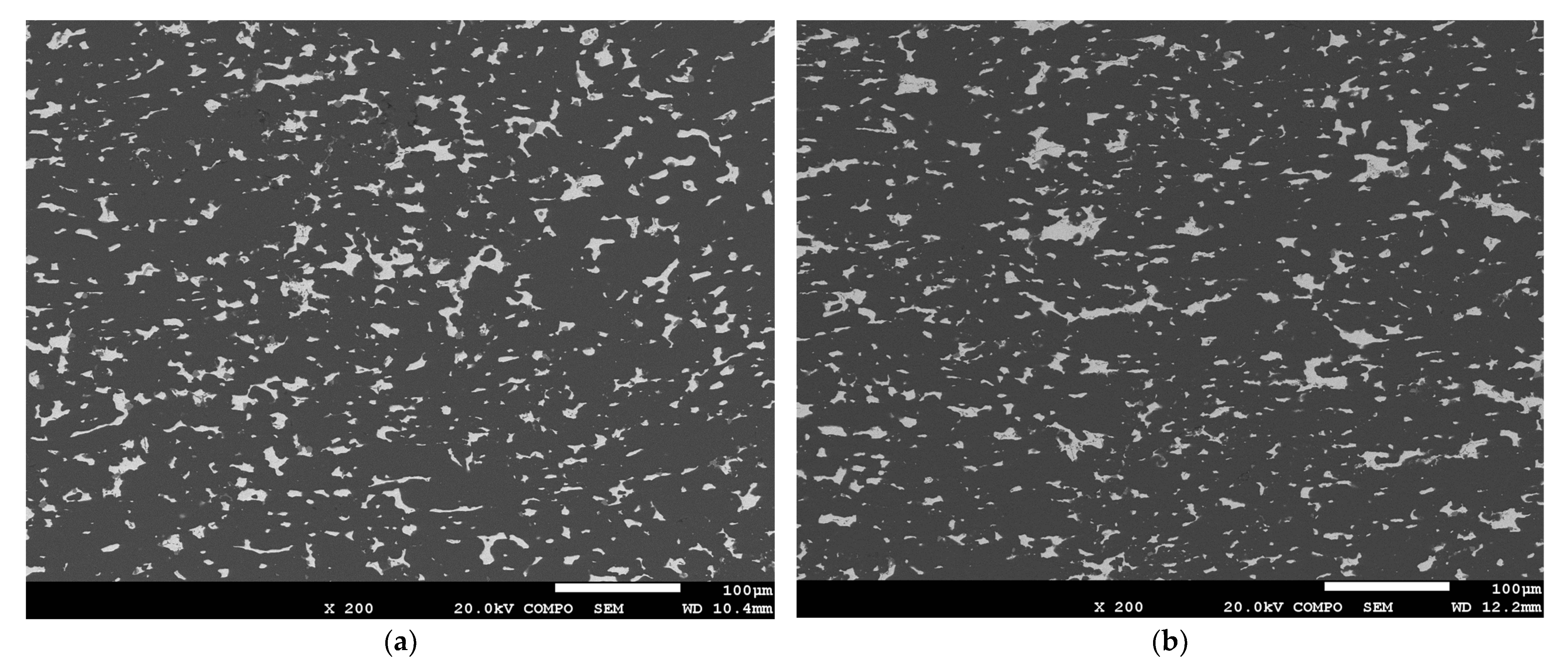
The tin phase of AlSn20Cu alloy products prepared by semi-solid die casting forms two shapes: nearly spherical and strips. The average particle diameter and total area ratio of the tin phase are 9.6 µm and 9.2%, respectively. The cooling rate of the semi-solid die casting process used in this study is not sufficient to prevent serious macro-segregation of the tin.
(3)
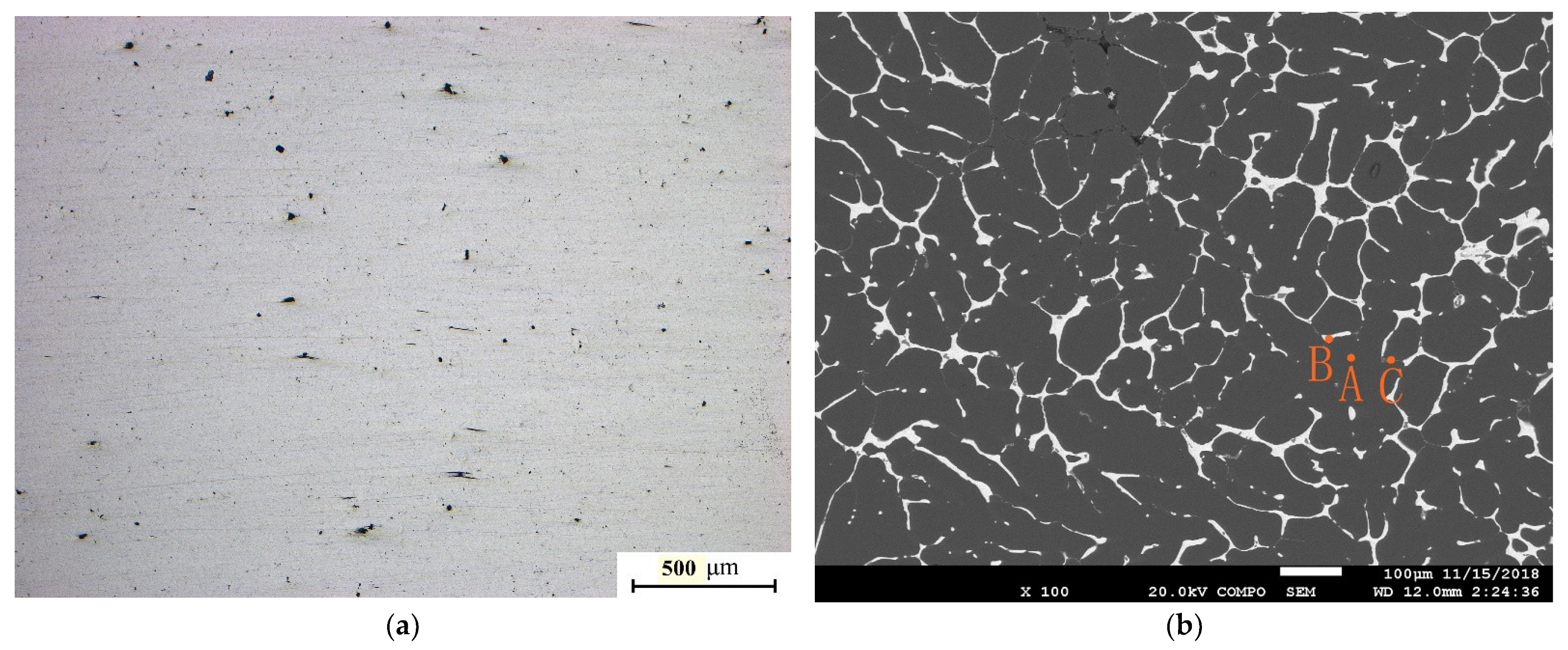
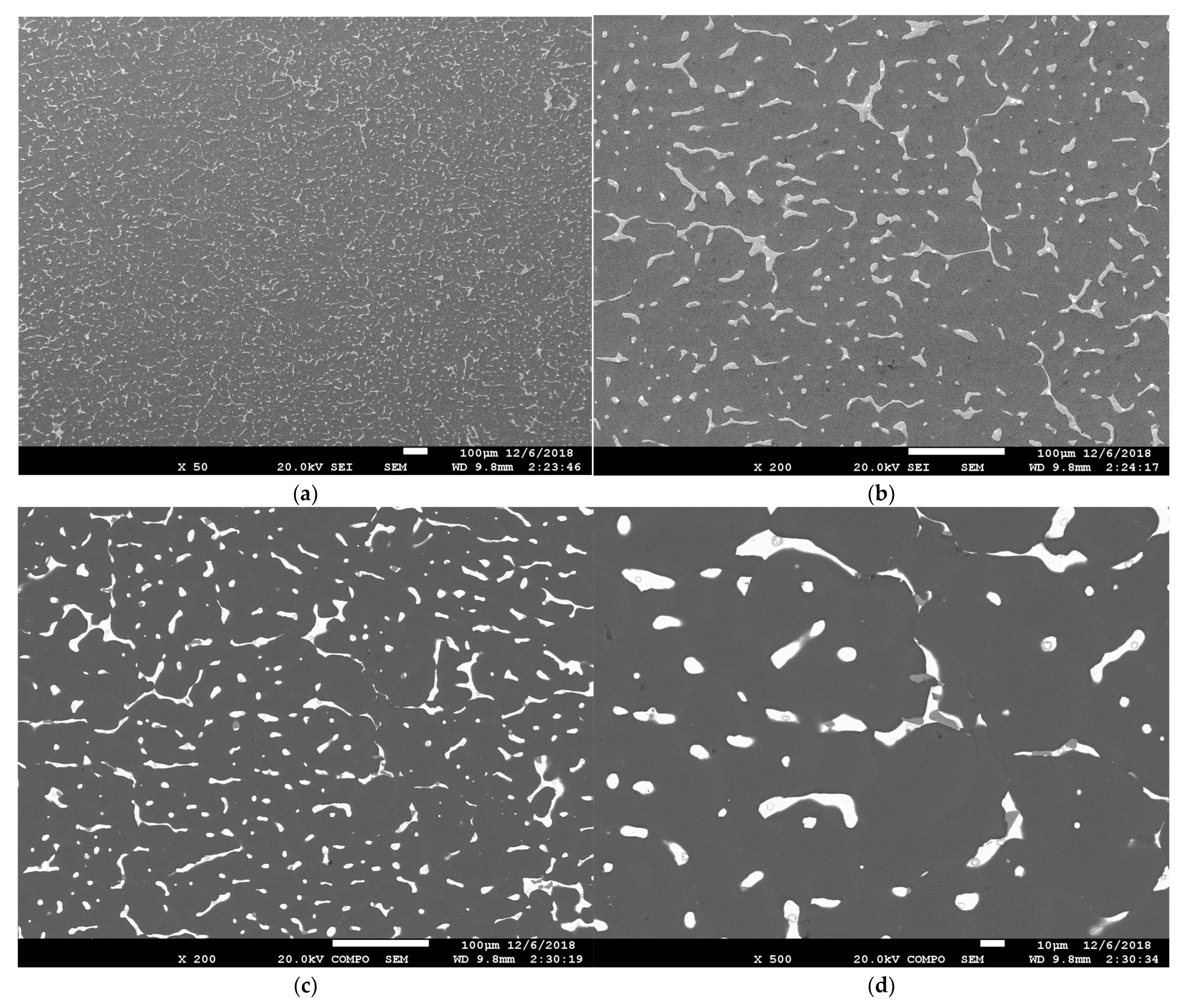
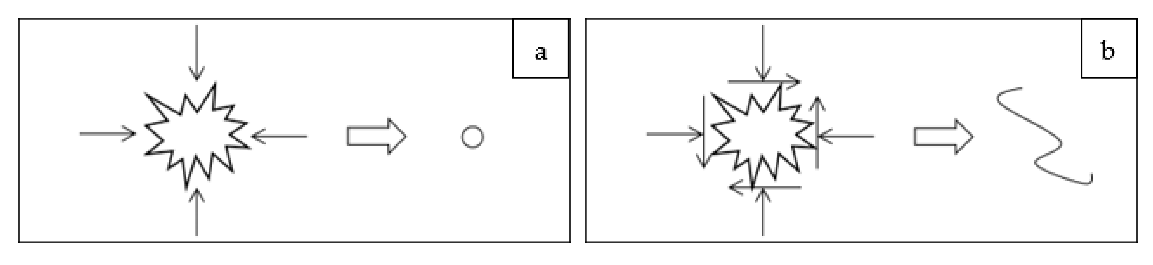
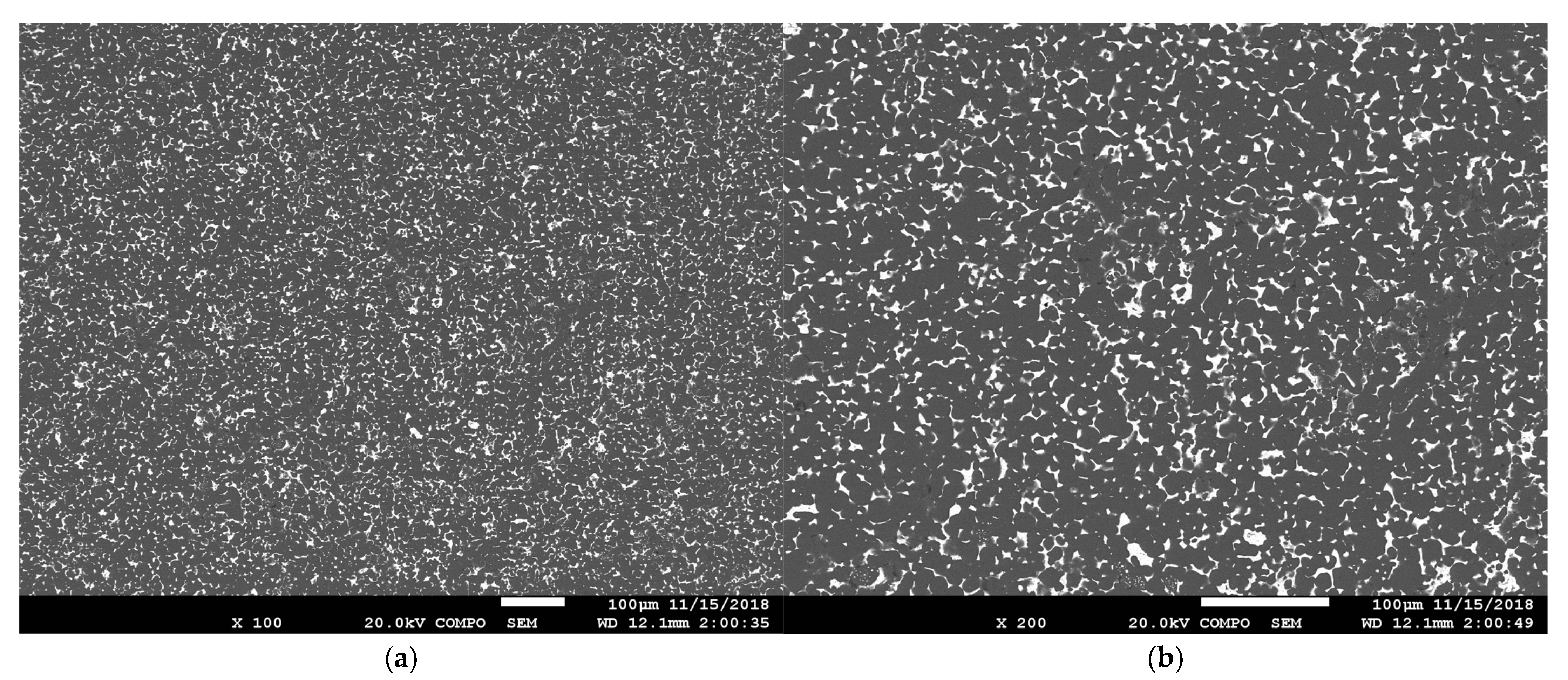
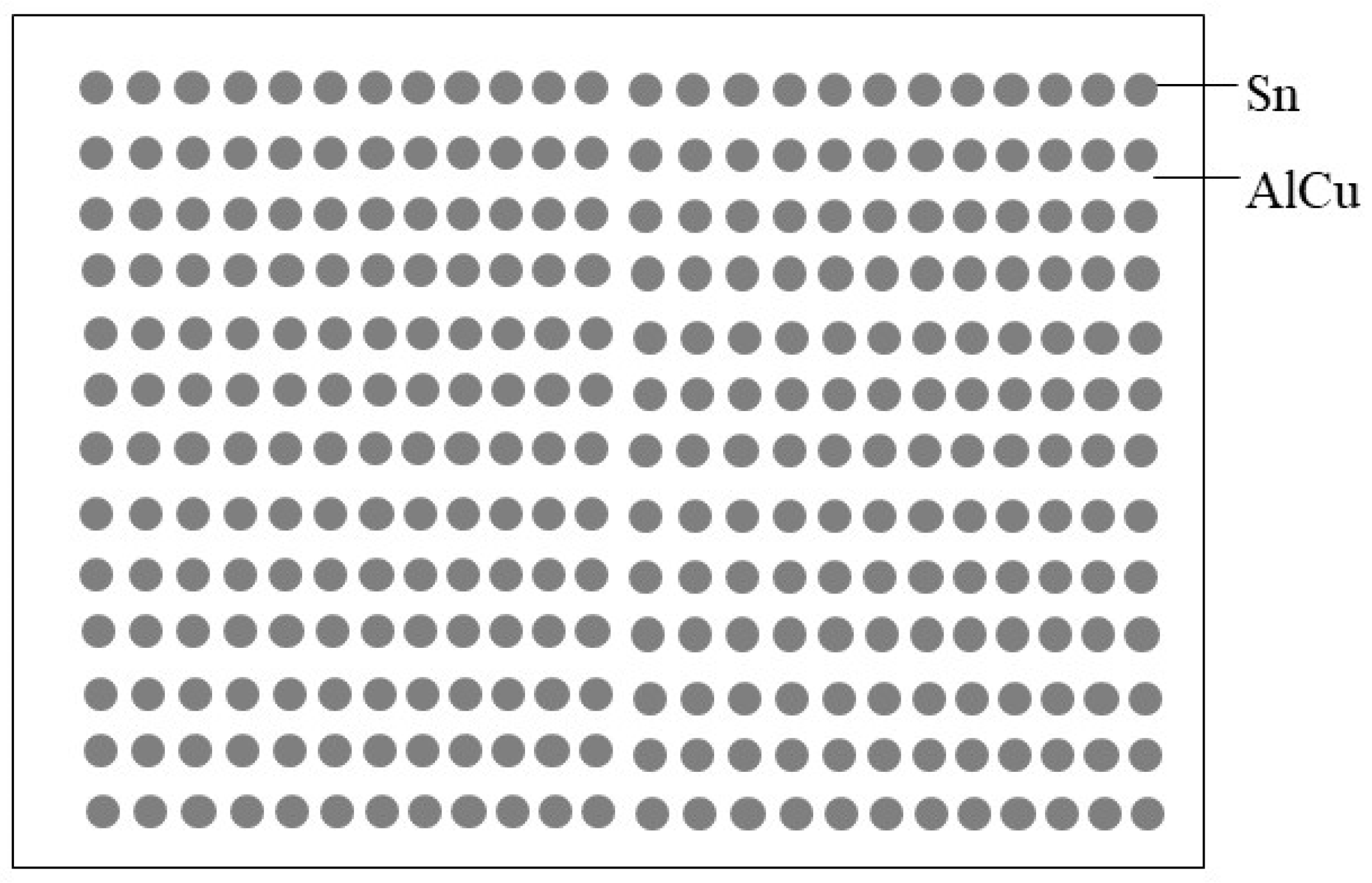
In the AlSn20Cu alloy prepared by spray forming, the tin phase is mostly equilateral, although there are some defects in the matrix. After hot extrusion at 215 °C, the defects are completely eliminated, and the tin-phase morphology remains almost unchanged. The average particle diameter and total area ratio of the tin phase are 6.2 µm and 13.8%, respectively.
(4)
The initial shape of the Sn phase is determined by both thermal and mechanical factors during preparation. A finer and more uniform tin-phase structure may be obtained by using the spray-forming process. Preparing an AlSn20Cu alloy by semi-solid die casting requires the shortest time of the three studied methods, and this method therefore presents a promising possibility for further optimization.

Author Contributions

Supervision, B.Z.; writing—original draft preparation, S.H.; writing—review and editing, S.H., B.Z. and Y.Z., and H.L.; investigations, S.W. and H.X. All authors have read and agreed to the published version of the manuscript.

Funding

This research received no external funding.

Data Availability Statement

Not applicable.

Conflicts of Interest

The authors declare no conflict of interest.

References

  1. Stuczynski, T. Metallurgical problems associated with the production of aluminium-tin alloys. Mater. Des. 1997, 18, 369–372. [Google Scholar] [CrossRef]
  2. Lu, Z.C.; Gao, Y.; Zeng, M.Q.; Zhu, M. Improving wear performance of dual-scale Al-Sn alloys: The role of Mg addition in enhancing Sn distribution and tribolayer stability. Wear 2014, 309, 216–225. [Google Scholar] [CrossRef]
  3. Bertelli, F.; Brito, C.; Ferreira, I.L.; Reinhart, G.; Nguyen-Thi, H.; Mangelinck-Noël, N.; Cheung, N.; Garcia, A. Cooling thermal parameters, microstructure, segregation and hardness in directionally solidified Al-Sn-(Si;Cu) alloys. Mater. Des. 2015, 72, 31–42. [Google Scholar] [CrossRef]
  4. Belova, N.A.; Akopyan, T.K.; Gershman, I.S.; Stolyarova, O.O.; Yakovleva, A.O. Effect of Si and Cu additions on the phase composition, microstructure and properties of Al-Sn alloys. J. Alloys Compd. 2017, 695, 2730–2739. [Google Scholar] [CrossRef]
  5. Bertelli, F.; Freitas, E.S.; Cheung, N.; Arenas, M.A.; Conde, A.; Damborenea, J.; Garcia, A. Microstructure, tensile properties and wear resistance correlations on directionally solidified Al-Sn-(Cu; Si) alloys. J. Alloys Compd. 2017, 695, 3621–3631. [Google Scholar] [CrossRef]
  6. Xu, K.; Russell, A.M. Texture strength relationships in a deformation processed Al-Sn metal-metal composite. Mater. Sci. Eng. A 2004, 373, 99–106. [Google Scholar] [CrossRef]
  7. Mirkovic, D.; Grobner, J.; Schmid-Fetzer, R. Liquid demixing and microstructure formation in ternary Al–Sn–Cu alloys. Mater. Sci. Eng. A 2008, 487, 456–467. [Google Scholar] [CrossRef]
  8. Schouwenaars, R.; Ramírez, E.I.; Romero, J.; Jacobo, V.H.; Ortiz, A. Fracture of thin cast slabs of Al-Sn alloys during cold rolling. Eng. Fail. Anal. 2012, 25, 175–181. [Google Scholar] [CrossRef]
  9. Hernández, O.; Gonzalez, G. Microstructural and mechanical behavior of highly deformed Al–Sn alloys. Mater. Charact. 2008, 59, 534–541. [Google Scholar] [CrossRef]
  10. Mahdavian, M.M.; Khatami-Hamedani, H.; Abedi, H.R. Macrostructure evolution and mechanical properties of accumulative roll bonded Al/Cu/Sn multilayer composite. J. Alloys Compd. 2017, 703, 605–613. [Google Scholar] [CrossRef]
  11. Liu, X.; Zeng, M.Q.; Ma, Y.; Zhu, M. Promoting the high load-carrying capability of Al-20 wt%Sn bearing alloys through creating nanocomposite structure by mechanical alloying. Wear 2012, 294–295, 387–394. [Google Scholar] [CrossRef]
  12. Xu, K.; Russell, A.M.; Chumbley, L.S.; Laabs, F.C. A deformation processed Al-20%Sn in-situ composite. Scr. Mater. 2001, 44, 935–940. [Google Scholar] [CrossRef]
  13. Patel, J.; Morsi, K. Effect of mechanical alloying on the microstructure and properties of Al–Sn–Mg alloy. J. Alloys Compd. 2012, 540, 100–106. [Google Scholar] [CrossRef]
  14. Lu, Z.C.; Zeng, M.Q.; Gao, Y.; Zhu, M. Significant improvement of wear properties by creating micro/nano dual-scale structure in Al-Sn alloys. Wear 2012, 296, 469–478. [Google Scholar] [CrossRef]
  15. Liu, X.; Zeng, M.Q.; Ma, Y.; Zhu, M. Wear behavior of Al-Sn alloys with different distribution of Sn dispersoids manipulated by mechanical alloying and sintering. Wear 2008, 265, 1857–1863. [Google Scholar] [CrossRef]
  16. Lavernia, E.J.; Ayers, J.D.; Srivatsan, T.S. Rapid solidification processing with specific application to aluminium alloys. Int. Mater. Rev. 1992, 37, 1–44. [Google Scholar] [CrossRef]
  17. Lavernia, E.J.; Gutierrez, E.M.; Szekely, J. Spray deposition of metals. Mater. Sci. Eng. A 1988, 98, 381–394. [Google Scholar] [CrossRef]
  18. Lucchetta, M.C.; Saporiti, F.; Audebert, F. Improvement of surface properties of an Al-Sn-Cu plain bearing alloy produced by rapid solidi cation. J. Alloys Compd. 2019, 805, 709–717. [Google Scholar] [CrossRef]
  19. Li, H.; Jiang, X.; Wang, X. Effects of Target Microstructure on Al-Cu Alloy Sputtering and Depositing Performance. Rare Met. 2009, 33, 442–445. [Google Scholar]
  20. Zhu, Q. Semi-solid moulding: Competition to cast and machine from forging in making automotive complex components. Trans. Nonferrous Met. Soc. 2010, 20 (Suppl. S3), sl042–sl047. [Google Scholar] [CrossRef]
  21. Atkinson, H.V.; Liu, D. Microstructural coarsening of semi-solid aluminium alloys. Mater. Sci. Eng. A 2008, 496, 439–446. [Google Scholar] [CrossRef] [Green Version]
  22. Tebib, M.; Morin, J.B.; Jersch, F.A. Semi-solid processing of hypereutectic A390 alloys using novel rheoforming process. Trans. Nonferrous Met. Soc. 2010, 20, 1743–1748. [Google Scholar] [CrossRef]
Figure 1. The equilibrium phase diagram of the AlSn20Cu alloy calculated by PANDAT: (a) the phase transition with increasing Sn content in Al–2Cu matrix, (b) the phase transition with increasing Cu content in Al–20Sn matrix.
Metals 12 01552 g001
Figure 2. Schematic diagram of the spray-forming process.
Metals 12 01552 g002
Figure 3. (a) Semi-continuous casting process, and (b) resulting AlSn20Cu alloy ingot.
Metals 12 01552 g003
Figure 4. (a) Metallographic and (b) SEM images of the AlSn20Cu alloy fabricated using semi-continuous-casting.
Metals 12 01552 g004
Figure 5. EDS analysis of semi-continuously cast AlSnCu alloy: the order corresponds to the points marked in Figure 4b. (a) point A, (b) point B, (c) point C.
Metals 12 01552 g005
Figure 6. XRD analysis of semi-continuously cast AlSnCu alloy.
Metals 12 01552 g006
Figure 7. Photos of the alloy specimen after hot compression tests.
Metals 12 01552 g007
Figure 8. Preparation process for an antifriction bearing bush blank produced using a semi-continuous cast AlSn20Cu alloy: (a) first hot rolling, (b) second hot rolling, (c) annealing, and (d) final milled sheet after cold rolling.
Metals 12 01552 g008
Figure 9. Scanning electron microscope (SEM) images of the final milled sheet: (a) S-T direction, and (b) L-S direction.
Metals 12 01552 g009
Figure 10. AlSn20Cu alloy billet produced using semi-solid die casting: (a) front view, and (b) side view.
Metals 12 01552 g010
Figure 11. SEM images of a billet produced using semi-solid die casting: (a,b) secondary electron imaging, (c,d) backscattered electron imaging.
Metals 12 01552 g011
Figure 12. Photo of spray-formed alloy ingot.
Metals 12 01552 g012
Figure 13. Metallographic photo of the spray-formed alloy ingot.
Metals 12 01552 g013
Figure 14. SEM image of the spray-formed alloy ingot. (a) magnified 200 times, (b) magnified 500 times.
Metals 12 01552 g014
Figure 15. Schematic diagram showing the densification process of hot isostatic pressing. 1: hot isostatic pressing furnace, 2: gas, 3: billet, 4: holder.
Metals 12 01552 g015
Figure 16. Schematic diagram showing the densification process of blocking hot extrusion. 1: Blocking extrusion die, 2: billet, 3: extrusion cylinder, 4: extrusion pad, and 5: extrusion rod.
Metals 12 01552 g016
Figure 17. Schematic diagram showing the effect of (a) hot isostatic pressing, and (b) blocking hot extrusion on gas-containing defects in the alloy.
Metals 12 01552 g017
Figure 18. SEM images of a spray-formed ingot after densification. (a) magnified 100 times, (b) magnified 200 times.
Metals 12 01552 g018
Figure 19. Ideal distribution of the tin phase in an aluminum–tin alloy.
Metals 12 01552 g019
Table 1. Result of quantitative analysis of Sn phase morphology.
Morphological Parameters of Tin PhaseOriginal StateFinal State
Semi-Continuous CastingSemi-Solid Die CastingSpray FormingSemi-Continuous CastingSemi-Solid Die CastingSpray Forming
Total area ratio
(%)
11.49.213.68.29.213.8
Quantity density
[number/(100µm)2]
8.412.639.36.512.640.2
Average particle area (µm2)135.872.632.8125.772.630.5
Average particle diameter (µm)13.19.66.512.69.66.2
Publisher’s Note: MDPI stays neutral with regard to jurisdictional claims in published maps and institutional affiliations.

