Article

Edge Microstructure and Strength Gradient in Thermally Cut Ti-Alloyed Martensitic Steels

1
ARC Research Hub for Australian Steel Manufacturing, University of Wollongong, Wollongong, NSW 2522, Australia
2
School of Mechanical, Materials, Mechatronic and Biomedical Engineering, University of Wollongong, Wollongong, NSW 2522, Australia
3
BlueScope Steel Limited, Five Islands Rd., Port Kembla, NSW 2505, Australia
4
Bisalloy Steels, 18 Resolution Drive, Unanderra, NSW 2526, Australia
*
Author to whom correspondence should be addressed.
Metals 2021, 11(7), 1138; https://doi.org/10.3390/met11071138
Submission received: 15 June 2021 / Revised: 13 July 2021 / Accepted: 16 July 2021 / Published: 19 July 2021
(This article belongs to the Section Metal Casting, Forming and Heat Treatment)

Abstract

:
Recently developed Ti-alloyed martensitic steels are believed to exhibit higher wear resistance than traditionally quenched and tempered medium carbon steels. However, their properties may deteriorate during thermal cutting and welding as a result of microstructure tempering. This would present significant challenges for the metal fabrication industries. A decrease in strength and wear resistance associated with tempering should vary with steel composition, initial steel microstructure and properties, and cutting method. In this work, we investigated the effect of thermal cutting on the edge microstructure and properties in two alloyed plate steels containing 0.27C-0.40Ti and 0.39C-0.60Ti (wt.%) commercially rolled to 12 mm thickness. Three cutting methods were applied to each of the two plates: oxy-fuel, plasma and water-jet. Microstructure characterisation was carried out using optical and scanning electron microscopy. With an increase in thermal effect, from water-jet to plasma to oxy-fuel, the heat affected zone width increased and hardness decreased in both steels. However, the hardness profile from the cut edge to the base metal significantly varied with steel composition, particularly C and Ti contents. The dependence of grain structure and precipitation kinetics on steel composition, and cutting method, were thoroughly investigated and linked to the hardness profile variation. The obtained results will be used to optimise the technological parameters for cutting and welding of Ti-alloyed martensitic steels.

1. Introduction

Martensitic steels are produced by quenching and tempering the hot rolled plates. Thus, they are usually designated as quenched and tempered (Q&T) steels. A combination of chemical composition (containing up to 0.36C, 1.55Mn, 0.55Si, 1.9Cr, 1Ni, 0.65Mo wt.%) and carefully chosen temperature and time of tempering result in a very strong and tough material with 360–600 HB of hardness, 500–1400 MPa of the yield stress (YS) and 600–1640 MPa of ultimate tensile strength (UTS) [1,2,3,4,5]. Due to their superior properties, Q&T steels are widely used in mining, defence and civil construction. Fabrication of the steel structures and units of heavy machinery is carried out using conventional cutting, bending and fusion arc welding processes. The main problem during fabrication is the formation of an edge microstructure highly susceptible to cold cracking [6,7,8,9,10,11,12,13]. Studies of the continuous cooling behaviour of Q&T armour steel highlighted that when steel is subjected to welding, the area surrounding the weld pool, known as the heat affected zone (HAZ), undergoes complex thermal cycles which cause microstructural changes in the material [8]. The extent and character of these changes depend on thermal cycles experienced and may lead to undesirable effects such as HAZ softening (or hardening) and hydrogen induced cold cracking (HICC). The degree of HAZ softening depends on several variables including chemical composition, temperature profile and kinetics of phase transformation [7].
Analysis of the literature data [14,15,16,17,18,19,20,21] for steels suggests that martensitic microstructures generally show a better abrasion resistance compared to other types of microstructure (ferrite, pearlite, bainite). The wear resistance of martensitic and bainitic steels can be improved by increasing the carbon content [22], in particular, due to the formation of hard carbides in a softer matrix [17,23,24]. However, an increase in hardness is usually accompanied by a decrease in toughness, leading to a decrease in wear resistance [25]. Thus, the carbon content should not exceed 0.45 wt.% C. To achieve a required combination of high strength and high toughness in commercially rolled plate steels, microalloying with carbide forming elements (such as Nb, V, Ti, Cr, Mo, W) can be used. High temperature precipitation and solute atoms retard the austenite grain growth (by pinning the grain boundaries) and help to refine the room temperature microstructure. Low temperature precipitation provides particle strengthening and may enhance the dislocation structure development. A combination of strengthening mechanisms operating in steel at room temperature results in simultaneous high strength and toughness. Due to the high prices of microalloying elements, cheaper Ti-alloyed steels were seen as advantageous [26,27,28].
This article is dedicated to the experimental evaluation of the thermal cutting effect on microstructure and hardness of Ti-alloyed wear resistant steels containing Ti-rich precipitates in a wide range of sizes. As the particle size distributions, grain structure and dislocation structure are expected to vary with heating, thermal cutting should affect the mechanical properties at the cut edge. A probable strength decrease in the HAZ is detrimental for the practical attributes of the studied steels, and, therefore, should be taken into account during edge preparation and welding. In this paper, three common cutting methods were investigated: oxy-fuel, plasma, and water-jet. As the precipitate size distributions and their response to an increasing temperature vary with steel composition, two steel chemistries, with higher and lower Ti and C contents, were studied.

2. Materials and Experimental Techniques

Two Ti-alloyed wear resistant plate steels commercially rolled to 12 mm thickness were studied in this work (Table 1). The steel containing relatively lower contents of carbon and titanium, namely 0.27 wt.% C and 0.40 wt.% Ti was designated as Steel L. Alternatively, the steel with higher carbon and titanium concentrations, 0.39 wt.% C and 0.60 wt.% Ti was designated as Steel H.
Oxy-fuel flame cutting was carried out using oxy-acetylene and oxygen gas cylinders. Prior to cutting, the steel plates were stored at room temperature (23 °C) with no preheating applied. The cutting was conducted manually at the speed of 304 ± 2 mm/min. Although the steel plate temperature during cutting was not measured, the torch temperature can reach as high as 3480 °C [29,30]. Gas cutting is achieved due to an exothermic chemical reaction occurring in steel that may be heated to a temperature at which the iron will rapidly oxidize in an atmosphere of high purity oxygen [31,32]. Plasma cutting was conducted using a Powermax 80 plasma cutting machine (produced by Hypertherm, Hanover, NH, USA). The samples were cut manually at room temperature (23 °C) with a speed of about 450 ± 50 mm/min. The plasma temperature may exceed 20,000 °C. When used for cutting, the plasma gas flow is increased so that the deeply penetrating plasma jet cuts through the material and molten material is removed in the efflux plasma. Water-jet cutting was carried out on a Maxiem 1530 machine (produced by Omax, Kent, OH, USA), using the Australian Garnet mesh 80 as an abrasive material. The samples were automatically cut at room temperature (24 °C) with an approximate speed of 128 mm/min. Evaluation of the HAZ strength and microstructure was carried out using hardness testing and optical and scanning electron microscopy. Up to 10 zones from the cut edge through the HAZ to the base metal were investigated for each of six studied conditions (two steel compositions cut with three cutting methods).
Hardness measurements were carried out on an automatic Matsuzawa Via-F Vickers hardness tester (manufactured by Matsuzawa, Akita, Japan); a 5 kg load was used for indentation. The hardness profile at the plate mid-thickness from the cut edge towards the base metal was plotted with a 0.5 mm step size. Each point on the hardness profile was calculated based on five indentations made in the plate through thickness direction.
Microstructure characterization was carried out using mainly optical and scanning electron microscopy (SEM). Optical and SEM sample preparation included polishing with SiC papers and diamond suspensions followed by etching with 5% Nital. The grain structure was analyzed using imaging on a Nikon Eclipse LV100ND optical microscope (manufactured by Nikon, Tokyo, Japan). Images were taken at two magnifications: ×50 and ×500 for measurements of HAZ sizes and parameters of coarse Ti-rich particles, respectively. Scanning electron microscopy of grain structure and fine Ti-rich and Fe3C particles was carried out using a JEOL JSM-7001F FEG scanning electron microscope (JEOL, Tokyo, Japan) operating at 15 kV of accelerating voltage. Images were taken at ×5000 and ×30,000 to evaluate the grain (martensite lath) sizes and parameters of fine Ti-rich and Fe3C particles. The average grain size was evaluated as an equivalent grain diameter. Energy dispersive X-ray spectroscopy (EDS) point analysis and element mapping were conducted to evaluate the chemistry of particles. For each condition: 200–350 coarse Ti-rich particles were measured using optical microscopy, up to 200 martensite laths were measured using SEM imaging, up to 30 particles were studied to access their chemical composition with EDS, and up to 400 of fine Ti-rich and 250–300 Fe3C particles were studied using analysis of SEM images. A JEOL JEM2010 transmission electron microscope (JEOL, Tokyo, Japan) was used to support the characterization of Fe3C particles. Thin foils of 3 mm diameter were prepared by fine polishing on SiC papers, followed by dimple grinding and ion milling on Gatan PIPS.

3. Results

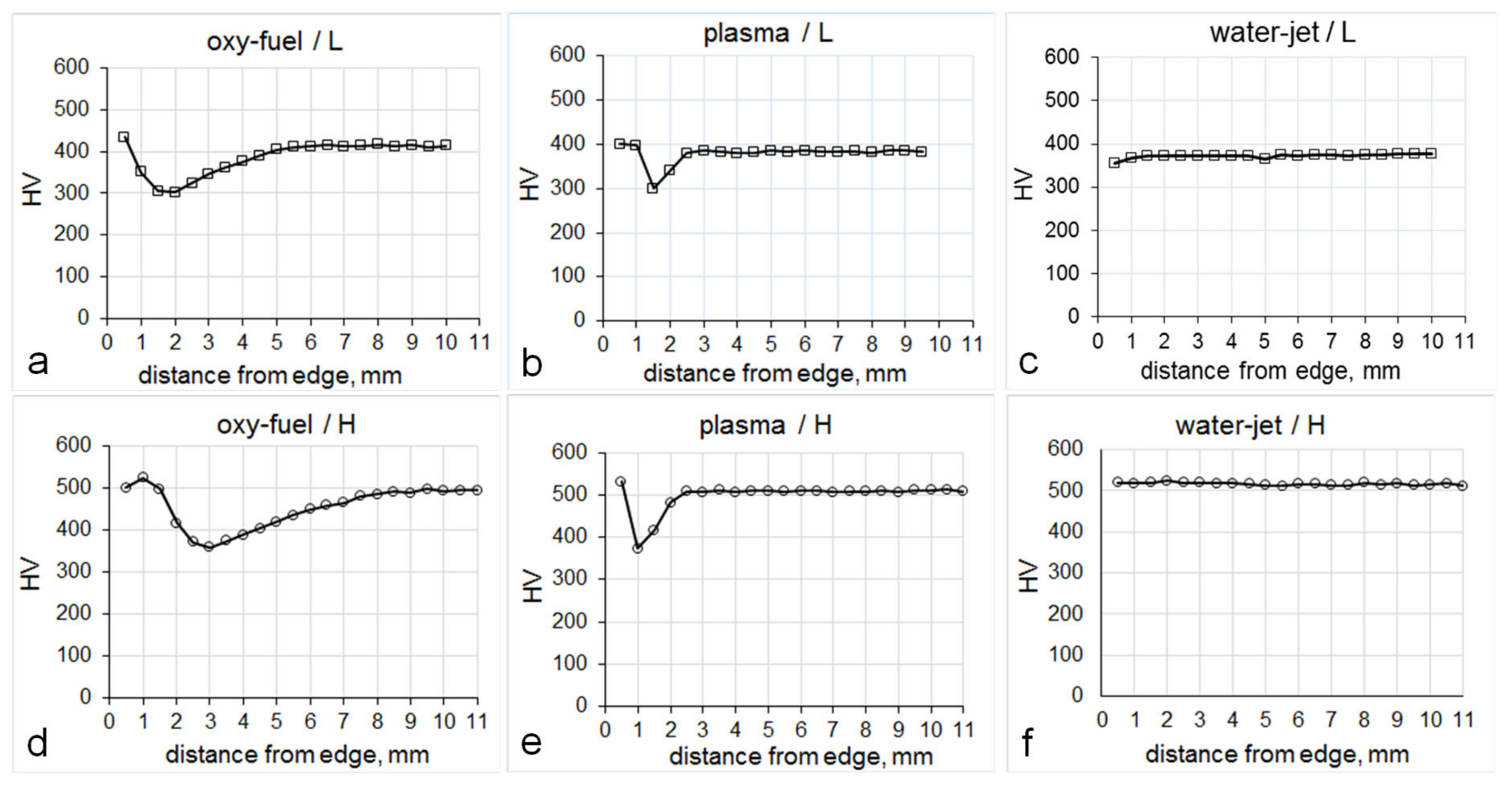
3.1. Hardness Profile

The HAZ width decreased with the cutting method from oxy-fuel to plasma to water-jet (Figure 1). Water-jet produces a negligible heat effect. The HAZ width variation observed by optical microscopy was supported by the measurements of hardness profiles from the cut edge towards the base metal (Figure 2). The hardness profile shape varied with the cutting method and steel composition, although the presence of a hardness minimum at a certain distance from the cut edge was observed previously in welded steels with acicular ferrite and bainite microstructure [33]. In Steel L both oxy-fuel and plasma cutting methods decreased hardness by a maximum of 100 HV from its original hardness of 400 HV (Figure 2a,b); and in Steel H this decrease was slightly higher, by about 130 HV from its original hardness of 500 HV (Figure 2d,e). Oxy-fuel resulted in about 5 and 9 mm wide HAZ in Steels L and H, respectively. In contrast, plasma cutting produced only 3 mm wide HAZ in both steels. In Steel L cut with oxy-fuel the minimum HV point was at about 2 mm from the cut edge (Figure 2a), although the plasma cutting resulted in the appearance of a minimum HV point at about 1.5 mm from the cut edge (Figure 2b). In Steel H cut with oxy-fuel the minimum HV point was at about 3 mm from the cut edge (Figure 2d), and in the plasma cut sample, the minimum HV point was at about 1 mm from the cut edge (Figure 2e). To explain such an intricate shape of the hardness profiles and their variation with steel composition and cutting method, the following microstructural characterization was undertaken.

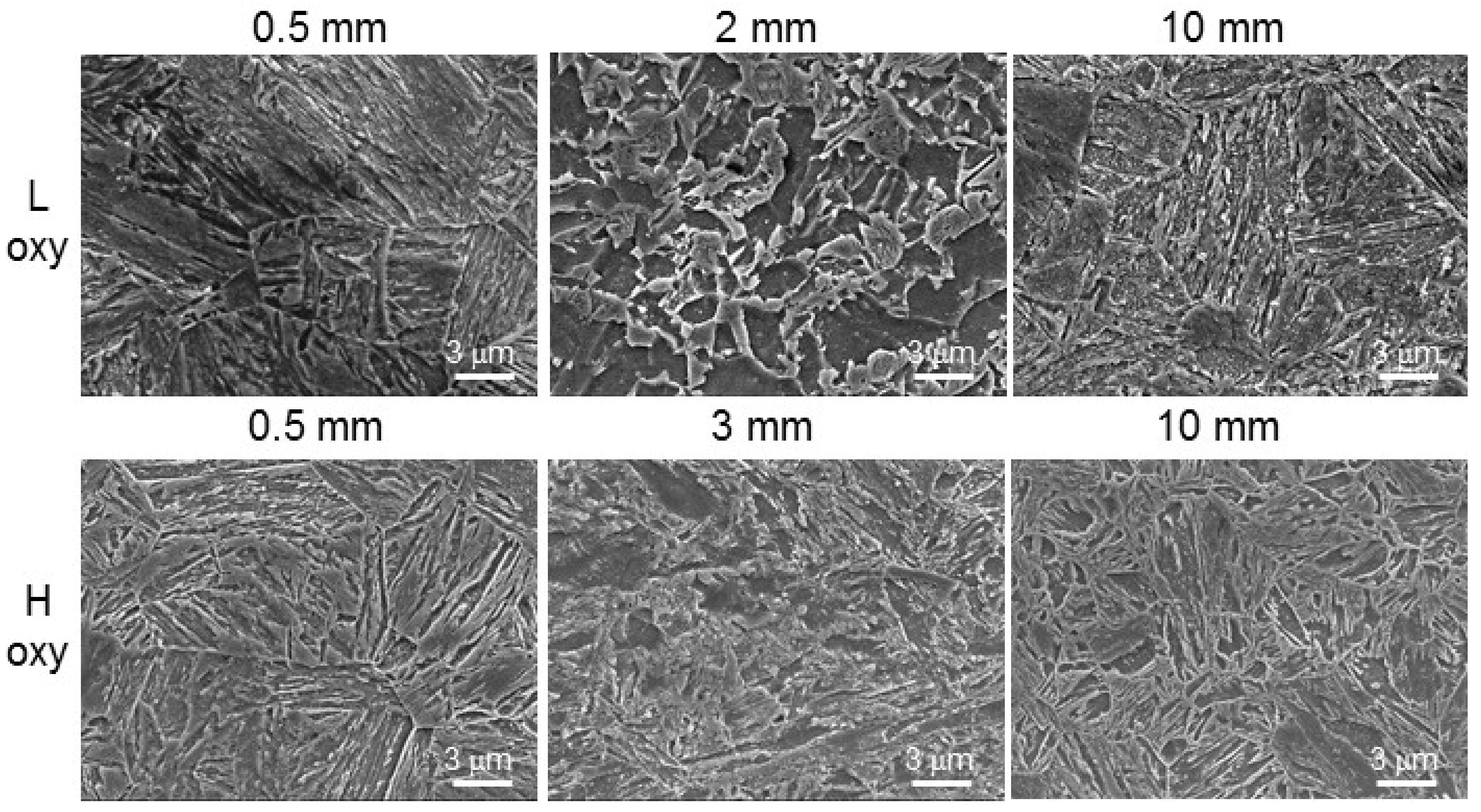
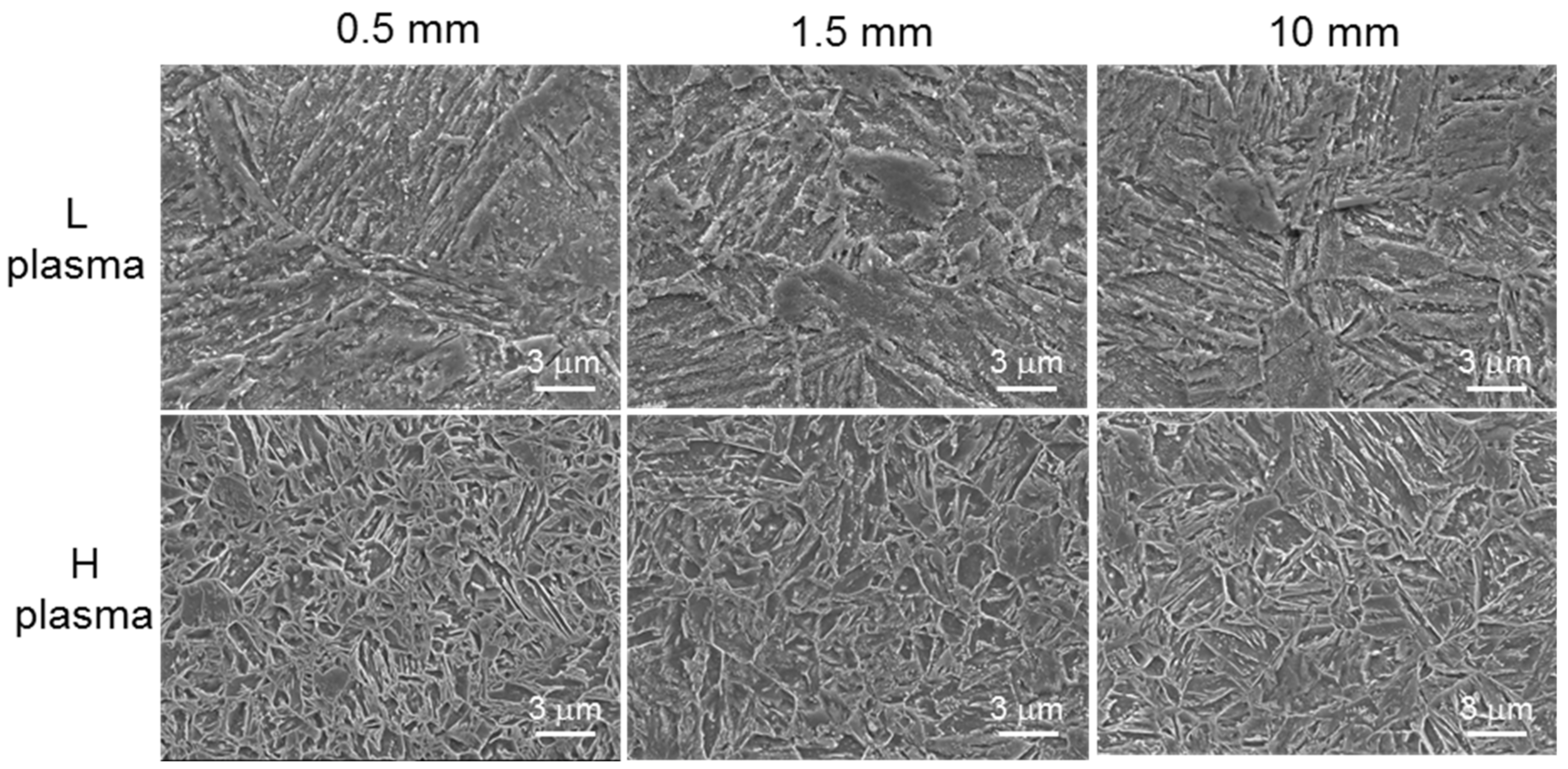
3.2. Grain Structure

In the as-received condition, both steel grades had a martensitic microstructure. SEM imaging of the cut samples revealed a variation in grain structure with distance from the cut edge.
In the oxy-fuel cut specimens (Figure 3), both steels exhibited a martensitic type of microstructure at the cut edge. A mixed bainite/tempered martensite microstructure was observed at the points of minimum hardness (2 and 3 mm away from the cut edge for Steels L and H, respectively), martensitic laths have almost disappeared, the grains were of irregular shape. Far away from the cut edge (10 mm), the microstructure was also of a martensitic type, as could be expected for this steel grade. In the plasma cut specimens (Figure 4), no significant variation in grain structure with the position was observed by SEM in both steels. Formation of complex phase balance in HAZ was reported previously for welded martensitic steels [34] and analyzed using an integrated microstructure modelling approach [35].
Measurements of the average grain size (equivalent diameter of martensite laths) are presented in Table 2. In both steels cut by oxy-fuel, the minimum average grain size was observed at the position of minimum hardness (2 and 3 mm from the cut edge for Steels L and H, respectively). In both steels cut by plasma, the grain size variation with position was within the measurement error. In the water-jet cut samples also no variation in grain size with position was observed. Both steels showed similar values of the average grain size in the base plate.

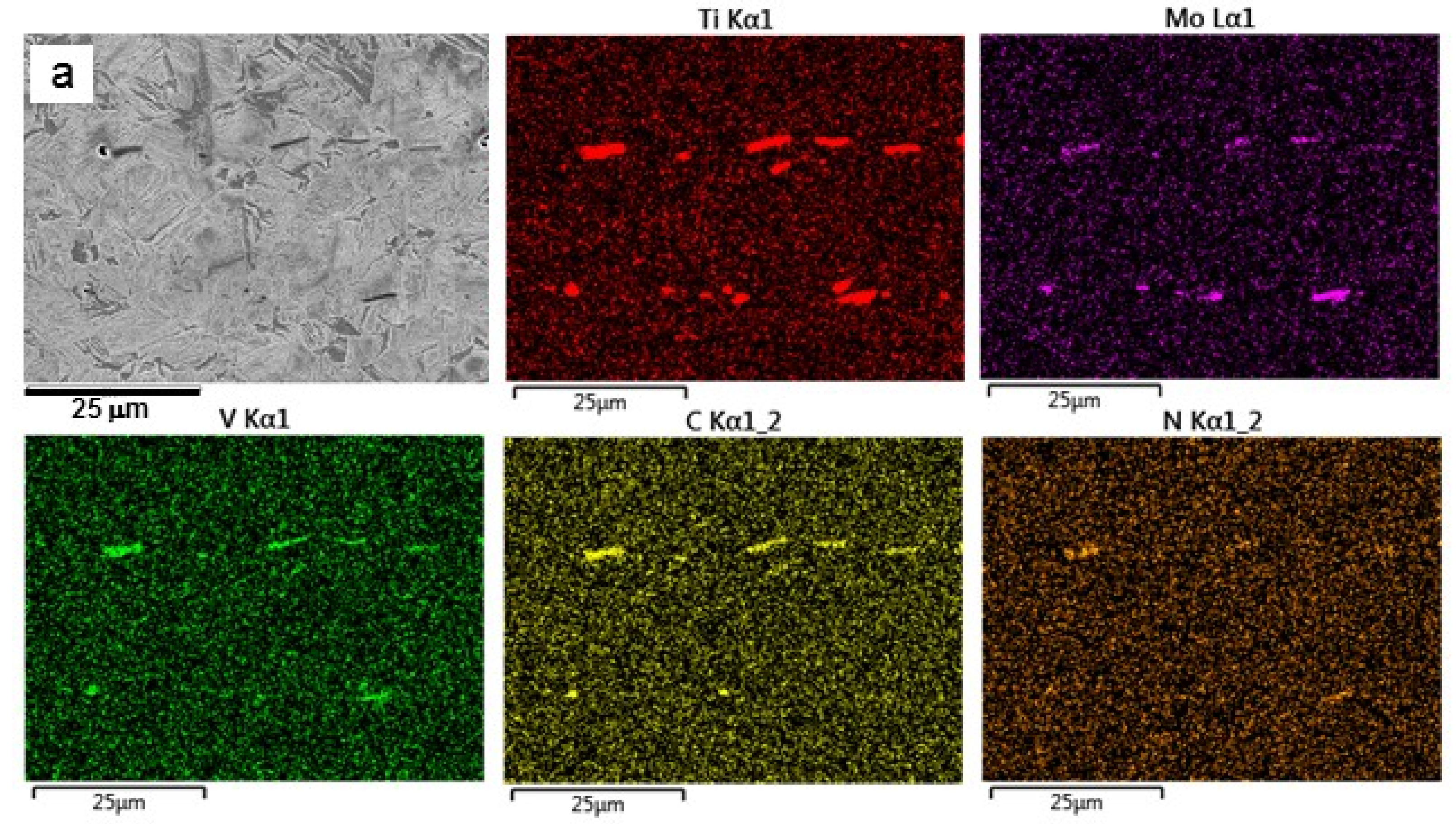
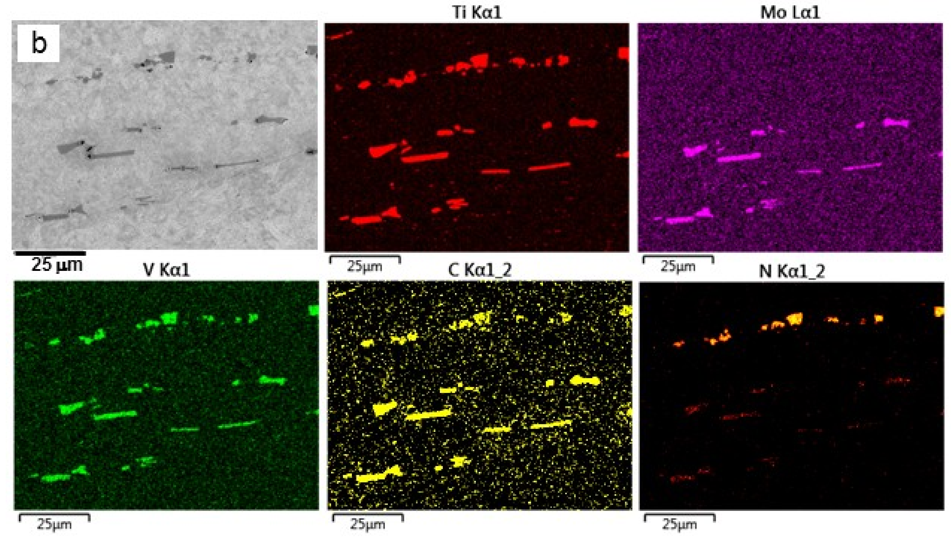
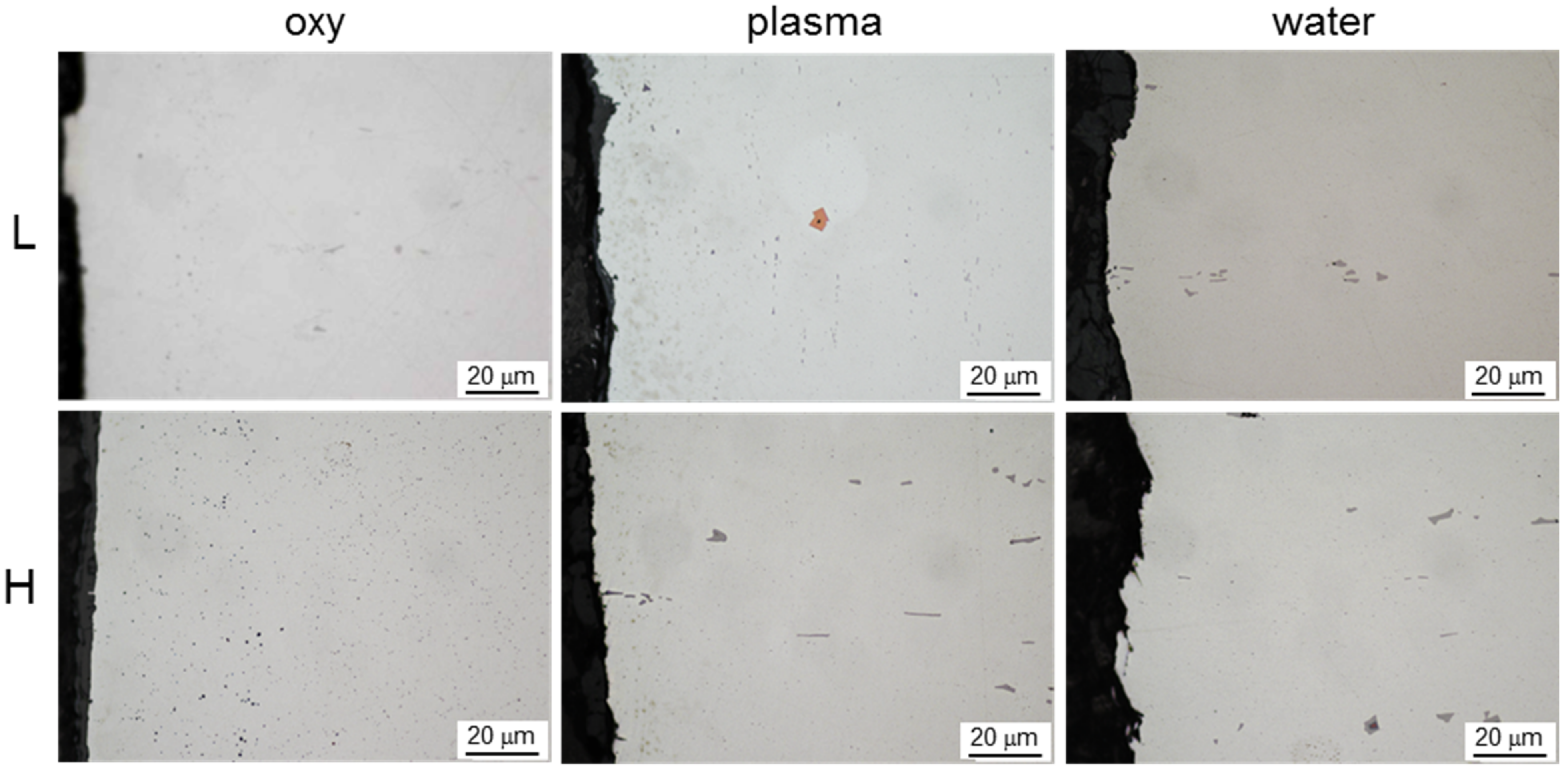
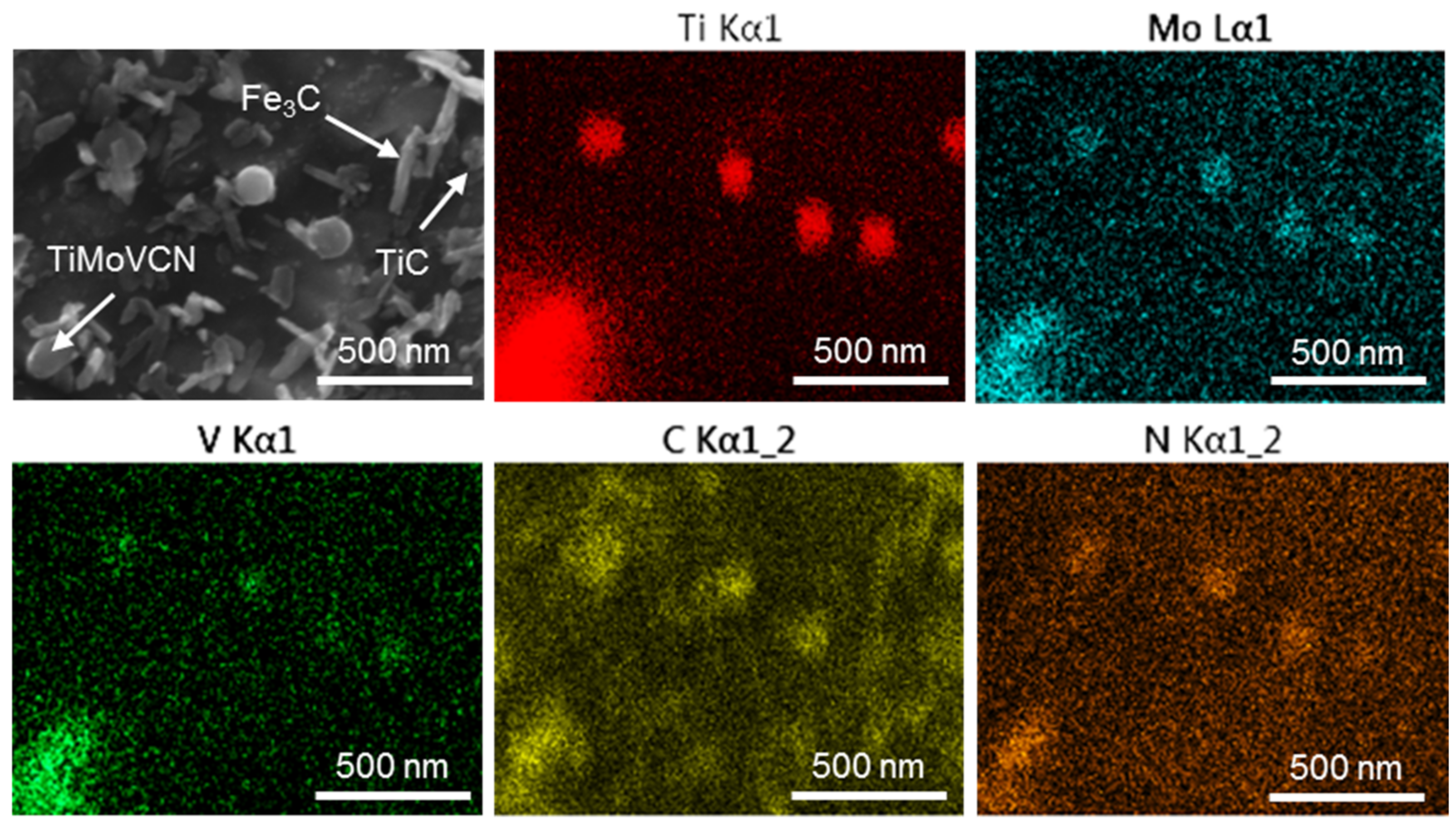
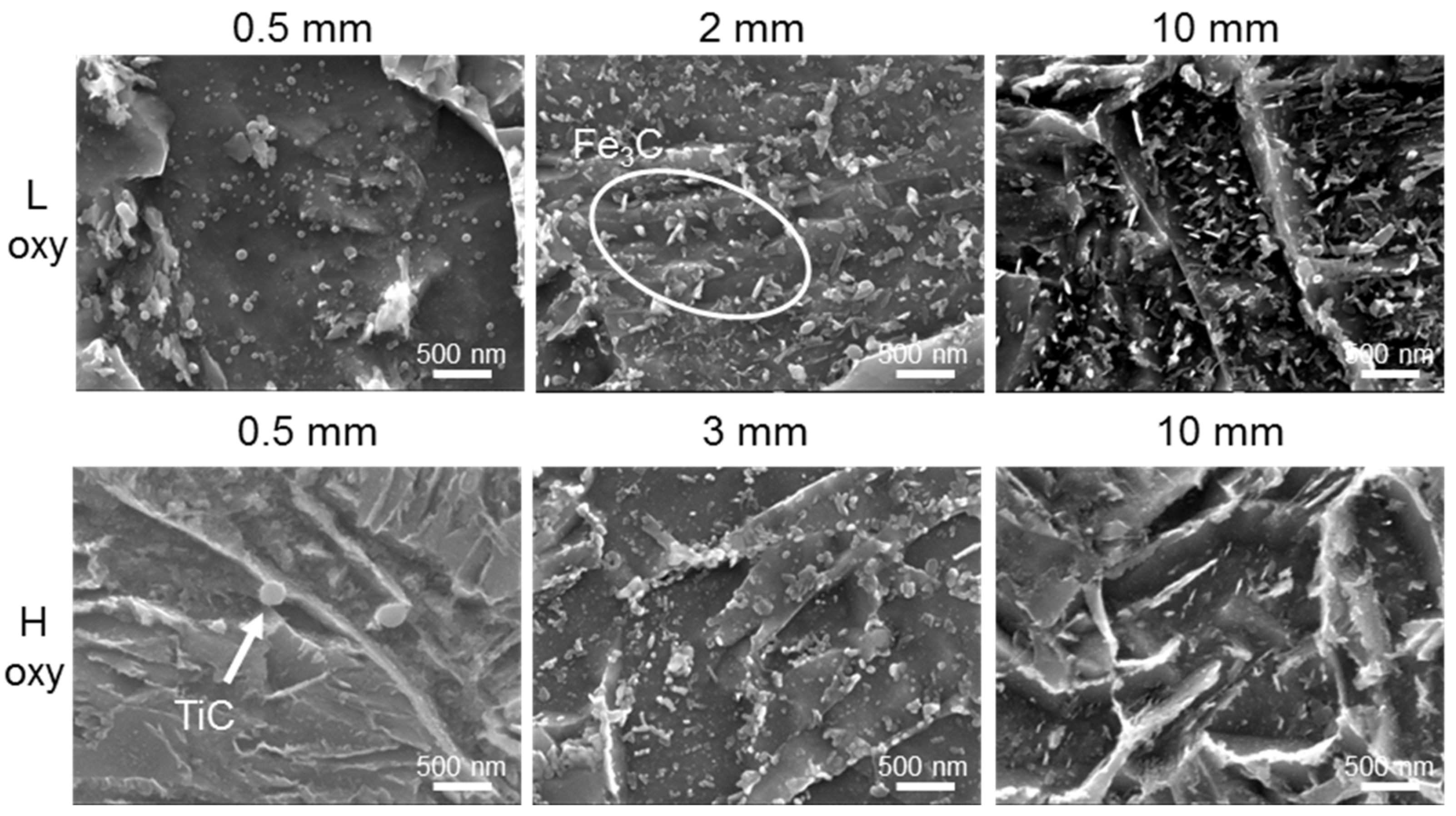
3.3. Coarse Ti-Rich Particles

Optical and SEM imaging revealed three particle types in the studied steels: coarse cuboidal/rectangular/elongated, fine spherical and fine needle-shaped. Presented below is a detailed analysis of these particles in the studied steels and the variation in the particle characteristics with cutting method and distance from the cut edge.
SEM-EDS mapping confirmed the coarse particles (0.4–6 μm) to be Ti-rich with various amounts of Mo, V, C, and N in both steels (Figure 5). The average particle sizes were larger in Steel H (Table 3), which is consistent with higher Ti, Mo and C contents in this steel (Table 1). Larger particles contained a higher nitrogen content. TiN particles are known to precipitate at higher temperatures, compared to TiMoV-rich carbides, therefore TiN usually have more time for growth. The particle parameters near the cut edge varied during cutting (Figure 6): coarse particles dissolved in Steel L, while in Steel H more particles precipitated. These behaviors seemed to be more pronounced in the samples cut with oxy-fuel compared to the plasma cut.
Analysis of the average (TiMoV)(CN) particle parameters (Table 3) suggested the following:
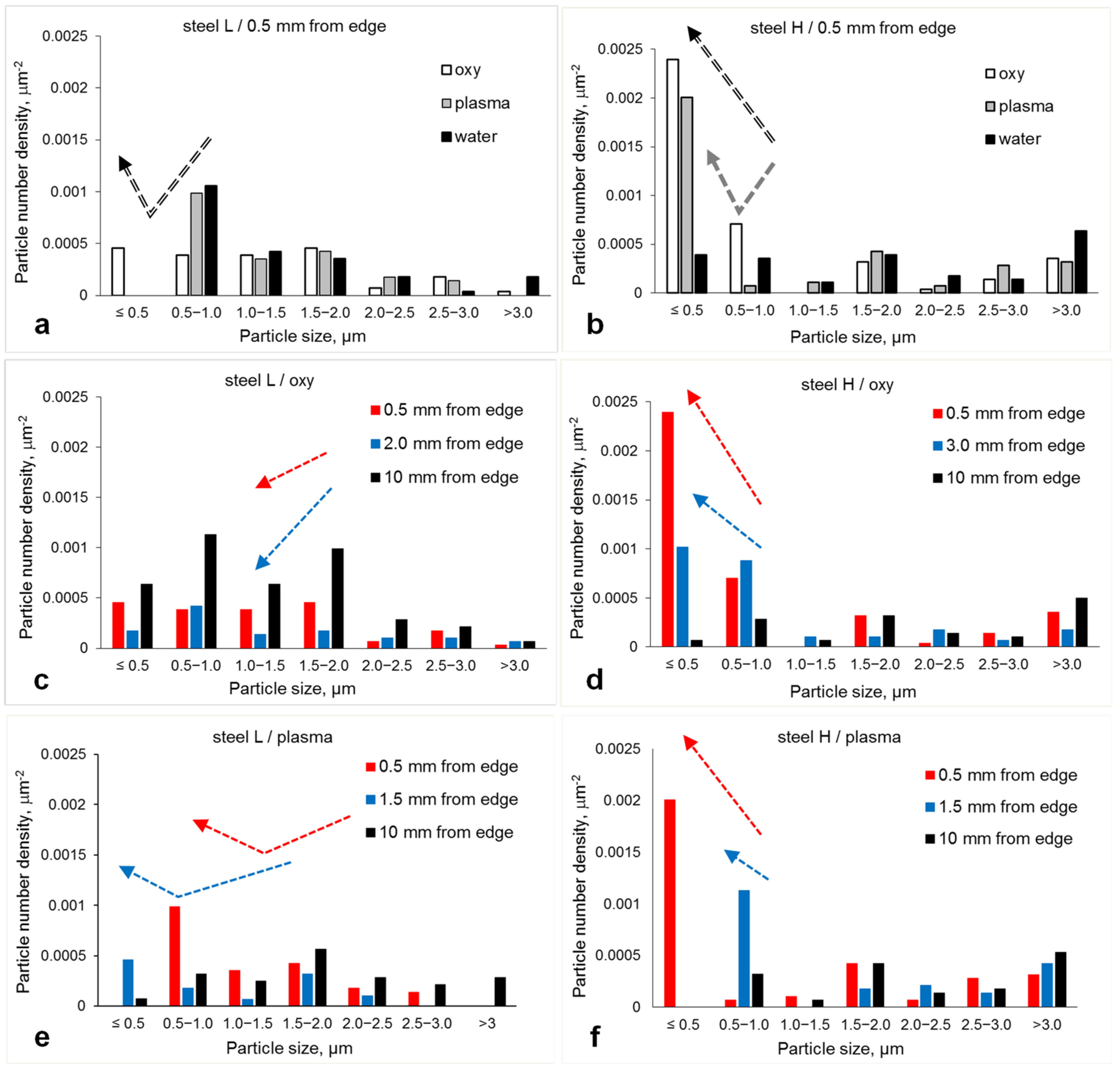
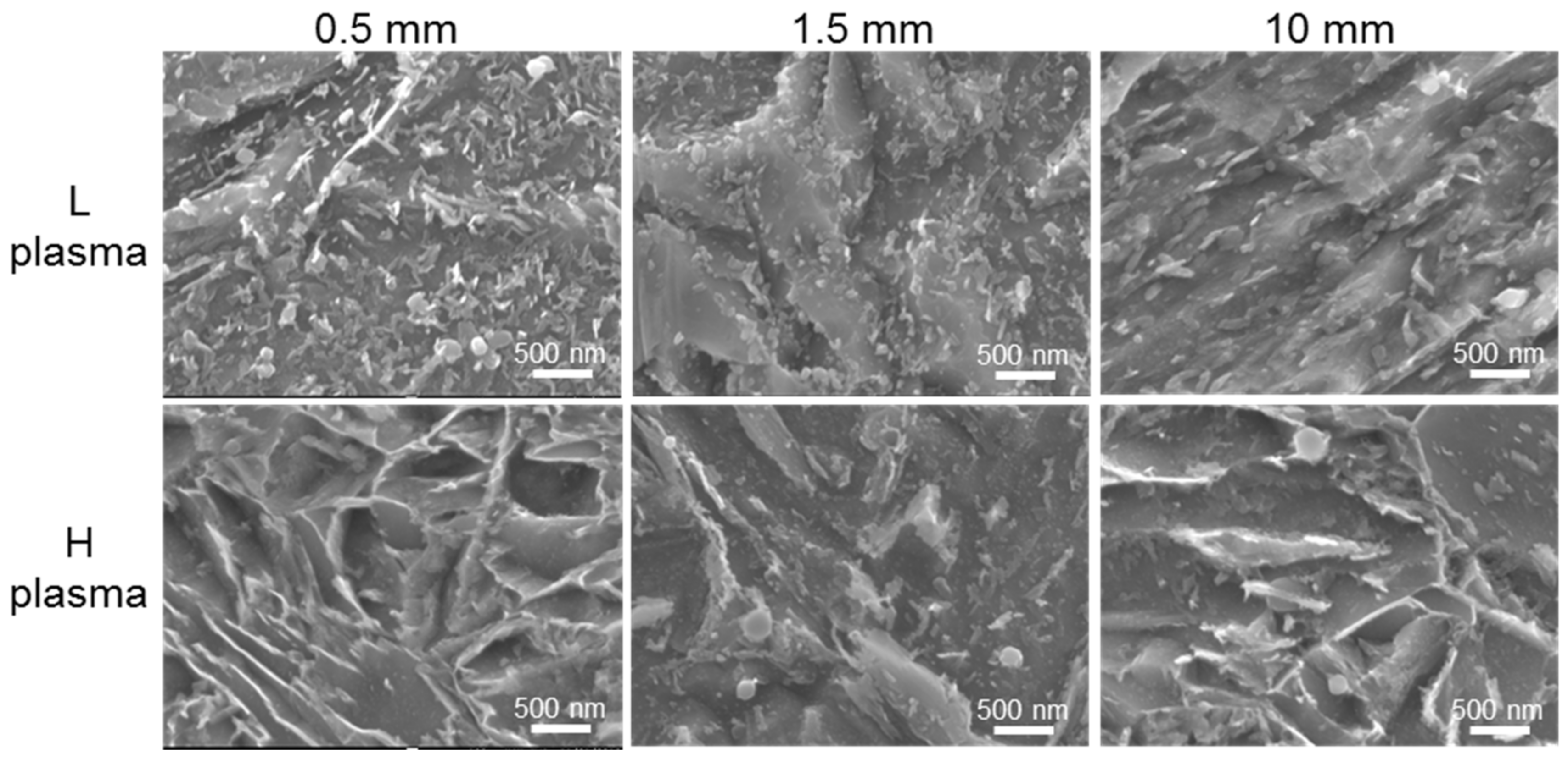
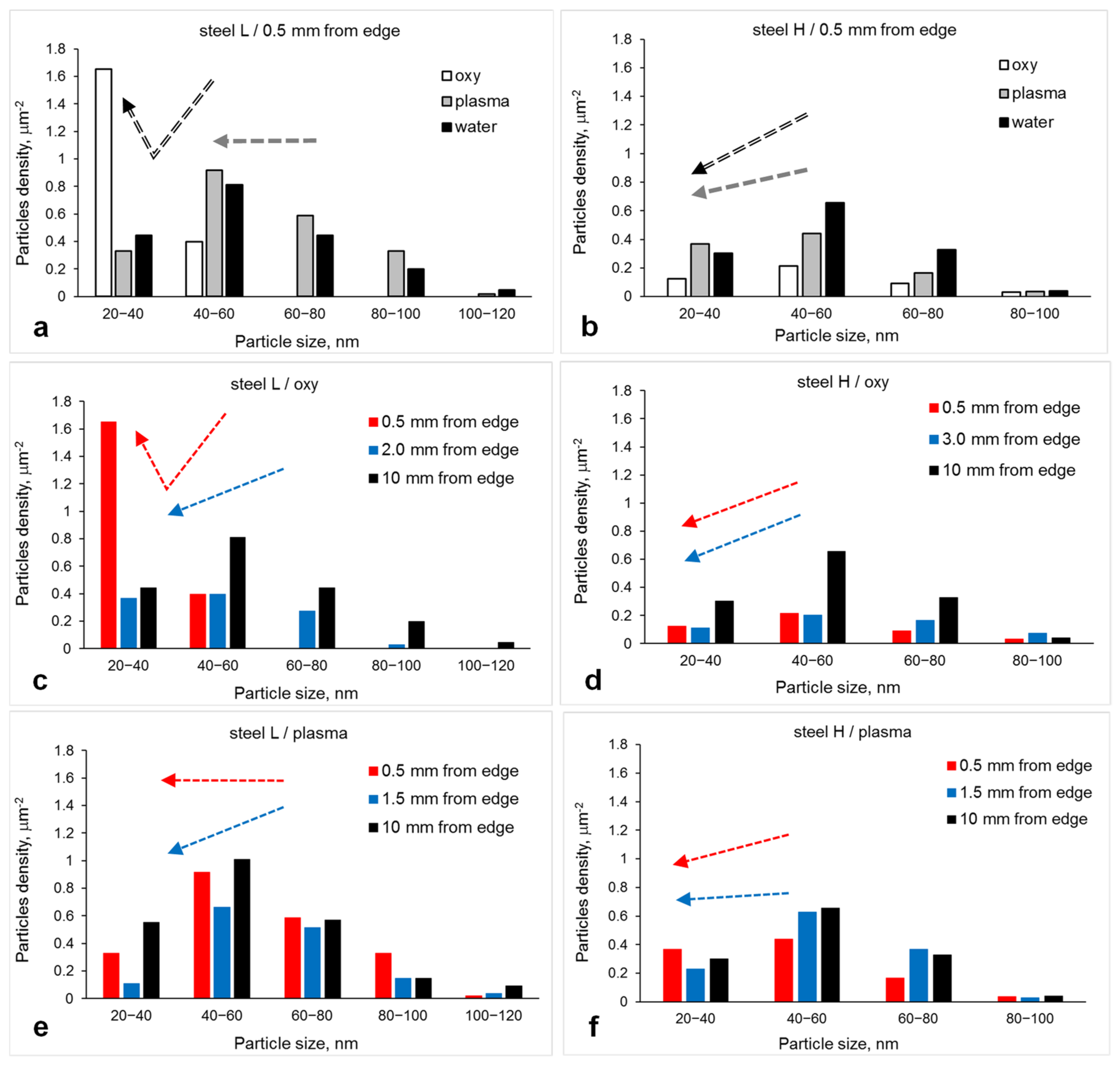
  • In Steel L thermal cutting with both methods led to a decrease in the particle number density well below the cut edge surface (2 mm for oxy-fuel and 1.5 mm for plasma, positions corresponding to minimum hardness); this supports particle dissolution. However, the average particle size at these positions increased after cutting with oxy-fuel and decreased after cutting with plasma. This could be explained if, during cutting with oxy-fuel, the dissolution was more intense (a wider particle size range fully dissolved); and during cutting with plasma, larger particles partially dissolved to smaller sizes. Closer to the cut edge (0.5 mm position) the particle number density and average size were similar to that in the base plate. This can be related to shorter times of heat effect associated with faster cooling rates on the surface.
  • In contrast, in Steel H cut with both oxy-fuel and plasma the particle number density significantly (near 2 times) increased towards the cut edge; this supports precipitation of new particles and the growth of smaller particles to larger sizes;
  • Cutting with water-jet did not lead to any variation in the particle parameters, due to the absence of heat effect.
To further elaborate on the (TiMoV)(CN) particle precipitation kinetics, the number density distributions for various cutting methods and positions have been analyzed (Figure 7). With respect to the cutting method, the following was observed closer to the cut edge (0.5 mm position):
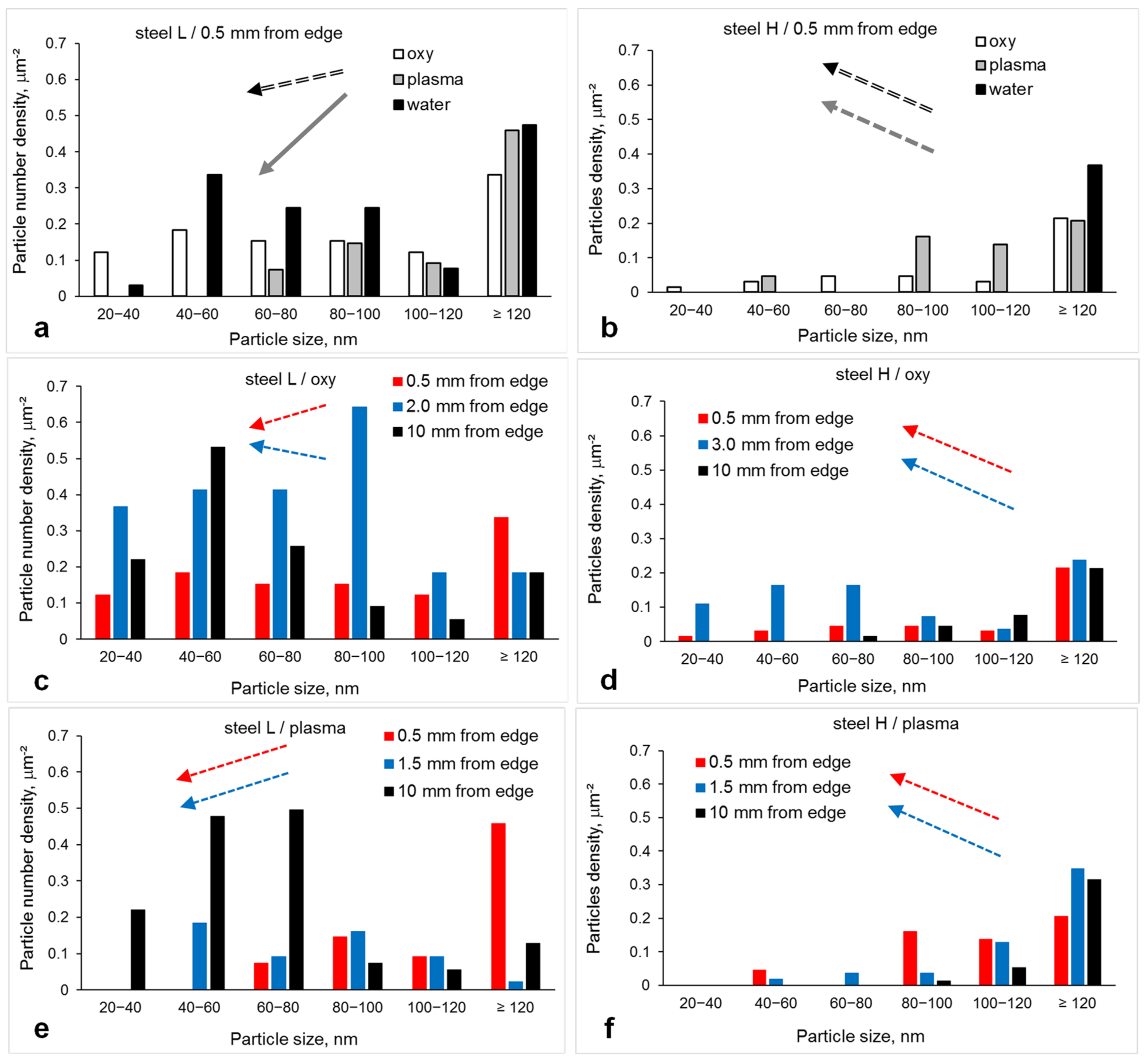
  • in Steel L cut with oxy-fuel, dissolution of 0.5–1.0 μm particles occurred (note a decrease in the number density of these particles accompanied by an increase in the density of <0.5 μm particles, Figure 7a), although cutting with plasma did not affect the distribution at this position;
  • in contrast, in Steel H cut with oxy-fuel new particles precipitated and grew in the <1.0 μm size range (note approximately 4 fold increase in these particles’ number density, Figure 7b); and cutting with plasma led to partial dissolution of 0.5–1.0 μm particles to <0.5 μm sizes and possible precipitation of new <0.5 μm ones.
  • With respect to distance from the cut edge during cutting with oxy-fuel:
  • in Steel L the particles in whole size range (<3 μm) dissolved, and this was to a greater extent at the 2 mm position compared to 0.5 mm position (Figure 7c);
  • in contrast, in Steel H <1.0 μm particles precipitated at both positions, and this was more intense at 0.5 mm distance from the cut edge compared to 3.0 mm (note an increase in the <1.0 μm particle number density by 9 and 5 fold at 0.5 and 3.0 mm positions, respectively, Figure 7d).
  • With respect to distance from the cut edge during cutting with plasma:
  • in Steel L > 1.5 μm particles dissolved at 0.5 mm position and >0.5 μm particles dissolved at 1.5 mm position (note decreases in their respective number densities, Figure 7e); this means that more particles dissolved at 1.5 mm position than at 0.5 mm position, which qualitatively corresponds to the trends observed for cutting with oxy-fuel;
  • in contrast, in Steel H < 1.0 μm particles precipitated at both positions and more at 0.5 mm than at 1.5 mm distance from the cut edge, which qualitatively corresponds to the behaviour observed during cutting with oxy-fuel.
Comparison of Figure 7c against e and Figure 7d against f suggests the following interesting point regarding the effect of cutting method. In Steel L cutting with oxy-fuel resulted in the particle dissolution in the whole size range; however, cutting with plasma led to partial dissolution (only >1.5 μm particles dissolved at 0.5 mm position and >0.5 μm particles dissolved at 1.5 mm position). In Steel H, particles precipitated and grew during cutting with both methods. However, the increase in <1.0 μm particle number density at 1.5 mm position (closer to the edge) during cutting with plasma was less (3.5 times) than this at 3.0 mm position (further away from the edge) during cutting with oxy-fuel (5 times). This indicates a more intense heat input during cutting with oxy-fuel leading to a more pronounced variation in the particle parameters.

3.4. Fine Ti-Rich Particles

Fine particles were of two types: spherical Ti-rich carbides and carbonitrides with various contents of Mo and V, and needle-shaped Fe3C (Figure 8). Their parameters varied with steel composition, cutting method and distance from the cut edge (Figure 9 and Figure 10). Analysis of fine Ti-rich particle parameters and their variation during cutting with respect to the as-rolled condition has shown that (Table 4):
  • in Steel L cut with oxy-fuel (i) the average particle size increased without a significant variation in number density at 0.5 mm position, and (ii) both the average particle size and their number density increased at 2 mm position. These might be explained if the growth of fine Ti-rich particles occurred. However, partially dissolving coarse (TiMoV)(CN) particles (discussed above) could also contribute to the increase in size and number density of fine Ti-rich ones. During cutting with plasma the number density decreased at both positions and the average size increased at 0.5 mm position. These support dissolution.
  • In Steel H cutting with both methods resulted in the particle number density and average size increasing. These indicate precipitation and coarsening of fine Ti-rich particles.
The particle number density distributions (Figure 11) supported a general dissolution of fine Ti-rich particles in Steel L and their precipitation and growth in Steel H, although there were certain variations with respect to cutting method and position. Thus, in Steel L the <80 nm particle number density decreased at 0.5 mm position after cutting with both oxy-fuel and plasma, and at 1.5 mm position after cutting with plasma (Figure 11a,c,e), although it slightly increased at 2.0 mm position after cutting with oxy-fuel. The number density of >80 nm particles increased at both positions (0.5 and 2.0/1.5 mm) after cutting with both methods (Figure 11a,c). These results mean that despite the general dissolution of fine Ti-rich particles, some coarsening could take place in Steel L. In Steel H the <120 nm particle number density increased at both positions (0.5 and 3.0/1.5 mm) after cutting with both methods (Figure 11b,d,f), and it was more pronounced during cutting with oxy-fuel. This clearly indicates precipitation and growth of new Ti-rich particles and is in line with the behaviour of coarse (TiMoV)(CN) particles presented above (Figure 7b,d,f).

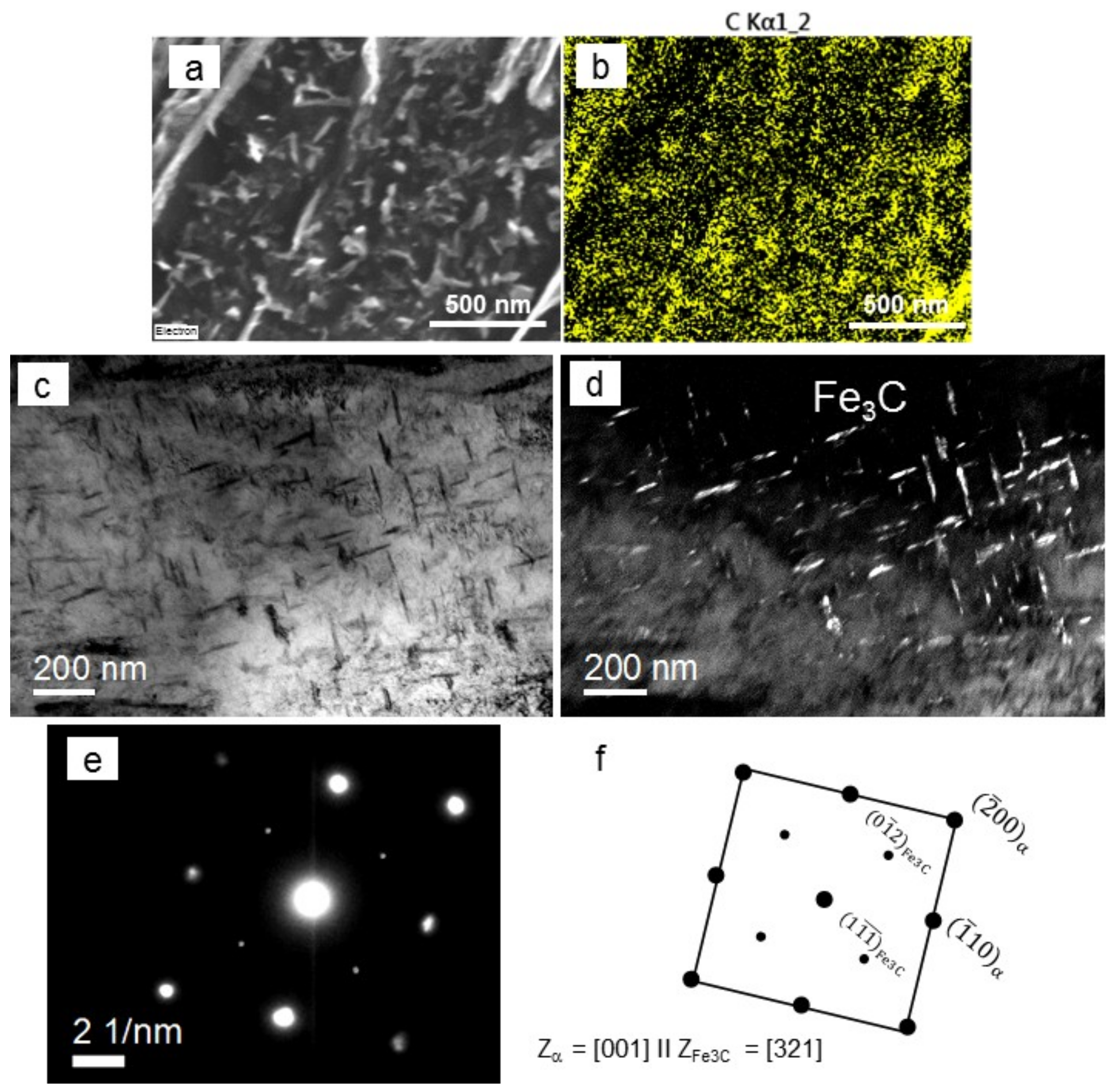
3.5. Fine Fe3C Particles

SEM imaging revealed the presence of needle-shaped particles with equivalent diameters being in the range of 30–115 nm for all studied conditions (Figure 12a). SEM-EDS mapping showed increased carbon concentrations in these particles and absence of other alloying elements (Figure 12b). This allowed to suggest that these particles were Fe3C. In addition to SEM characterization carried out for all studied conditions, a TEM study was performed for the as-received steels (Figure 12c,d). Analysis of the diffraction patens showed the Fe3C particles exhibiting Bagaryatskii orientation relationship to the bcc (tempered martensite) matrix: [001]matrix‖[321]Fe3C (Figure 12e,f). This can further support their nature as Fe3C.
In Steel L, the average Fe3C particle number density decreased for both cutting methods, and their size could increase slightly during plasma cutting (Table 5). The decrease in number density was higher away from the cut edge, 2.0 mm position for oxy-fuel cutting and 1.5 mm for plasma cutting, where a longer thermal effect could be expected. The number density distributions supported a decreasing number of >40 nm Fe3C particles, and it was more pronounced during cutting with oxy-fuel (Figure 13a,c,e). This evidence points to the dissolution of Fe3C particles in Steel L during thermal cutting.
However, in Steel H the average particle size increased slightly during cutting with oxy-fuel despite a decrease in number density (Table 5). In addition, during cutting with plasma, no significant variation in the average particle parameters was observed. The number density distributions supported decreasing numbers of particles in the whole size range during oxy-fuel cutting (Figure 13b,d,f), and very minor variations during cutting with plasma. These indicate partial dissolution of Fe3C particles in Steel H, more pronounced during cutting with oxy-fuel.

4. Discussion

4.1. Effect of Steel Composition

The average particle parameters and hardness values with respect to steel composition and cutting method are summarised in Table 6. In as-received condition (10 mm away from the cut edge), the grain size was similar in both steels, the number densities of coarse (TiMoV)(CN) and fine Ti-rich particles were higher in Steel L (although their sizes were larger in Steel H, Table 3 and Table 4), and the number densities of Fe3C particles were also higher in Steel L. Larger sizes of coarse (TiMoV)(CN) and fine Ti-rich particles correspond to higher contents of Ti, Mo and C in Steel H (Table 1). However, lower number densities of all particle types in Steel H is an unusual result. Higher concentrations of Ti and C increase the solubility products of TiN and TiC particles [36,37] and their precipitation start temperatures, traditionally this leads to higher particle number densities at room temperature [38,39,40]. Probably, the rolling of Steel H was conducted at high speed, accelerated cooling might also have been used at the end of the hot rolling cycle. These techniques would result in the matrix super-saturation with Ti, Mo and C and solid solution strengthening. Consequently, the hardness of Steel H was higher than that of Steel L.
During cutting with oxy-fuel, the Ti-rich particles exhibited different types of precipitation kinetics in the two steels. Thus, in Steel L the number density of coarse (TiMoV)(CN) particles decreased and that of fine Ti-rich particles increased towards the cut edge. This indicates dissolution of the coarse particles to smaller sizes in Steel L. In contrast, in Steel H, the number densities of both coarse and fine Ti-rich particles increased towards the cut edge. This indicates precipitation and growth of new particles in Steel H. Such a discrepancy in the Ti-rich particle behaviour can be related to two reasons: (i) Ti, Mo and C concentrations in the matrix were higher in Steel H; during thermal cutting the Ti, Mo and C atoms diffused to the existing particles contributing to their size growth and diffused to each other to form new Ti-rich particles; and (ii) the solubility temperature of Ti-rich particles was lower in Steel L; this would result in fewer undissolved coarse particles in Steel L after heating during cutting. In fact, the solubility equation log[Ti]·[C] = 2.75 − 7000/T presented in [37] gave 1575 °C and 1942 °C for TiC dissolution temperature in Steel L and H, respectively. A decreasing number density of Fe3C particles in both steels (nearly twofold drop) coincided with an increasing number density of Ti-rich particles. Dissolution of cementite in favour of alloying element carbide precipitation was observed following tempering of martensite [41].
In both steels, the grain size slightly decreased below the cut edge (2.0 and 3.0 mm positions in Steels L and H, respectively) due to recrystallization [42]. However, the microstructure resembled freshly transformed martensite closer to the edge (0.5 mm position, Figure 3). This could be explained if, due to heating from oxy-fuel, the original martensite closer to the edge transformed to austenite and back to martensite during cooling. The grain size at the edge (0.5 mm position) was slightly larger in Steel H (3.0 μm) compared to Steel L (2.3 μm). This can be associated with two reasons: (i) fine Ti-rich particles exhibiting a lower number density in Steel H were less effective in retardation of austenite grain growth in Steel H compared to Steel L; and (ii) the ferrite to austenite transformation temperature was lower in Steel H, 770–785 °C, than in Steel L, 835–845 °C (calculated using various formulas presented in [43,44]). The latter would give added time for the matrix to be in austenitic condition and, consequently, more time for austenite grain growth.
In spite of decreasing grain size and increasing number density of fine Ti-rich particles, hardness decreased in Steel L at the 2.0 mm position. This corresponds to the decrease in the number density of coarse (TiMoV)(CN) and Fe3C particles. In Steel H, a minimum hardness was also observed; although, in contrast to Steel L, the number density of coarse (TiMoV)(CN) particles increased in addition to increasing number density of fine Ti-rich particles. This supports the following conclusions: (i) the grain structure recovery (dislocation annihilation) and recrystallization in the HAZ can significantly contribute to a hardness decrease, irrespective of the particle precipitation kinetics, because the number of dislocation-obstacle interaction sites is responsible for strength, and not the number of particles dispersed in the matrix; (ii) precipitation of coarse (TiMoV)(CN) and fine Ti-rich particles cannot fully compensate for the dissolution of Fe3C, and (iii) solution depletion in C (due to precipitation of excessive amount of fine Ti-rich carbides) is detrimental for hardness.
Closer to the cut edge (0.5 mm position), the hardness increased in both steels. Obviously, a reverse martensite-austenite-martensite transformation resulted in a higher dislocation density at the cut edge in both steels. Lower heat effect times, due to faster cooling of the edge compared to the 2.0 mm position, resulted in less severe particle dissolution in Steel L. In Steel H, significant precipitation of coarse (TiMoV)(CN) particle might have contributed to the hardness increase at the edge.
During cutting with plasma, in Steel L the number densities of coarse (TiMoV)(CN), fine Ti-rich and Fe3C particles decreased at the 1.5 mm position from the cut edge (simultaneously with a size growth of fine Ti-rich and Fe3C particles, Table 4 and Table 5). This indicates dissolution of all particles in Steel L. In contrast, in Steel H, the (TiMoV)(CN) and fine Ti-rich particles precipitated and grew, although Fe3C dissolved, and these behaviours were more pronounced closer to the edge (at 0.5 mm position). This is in line with the matrix super-saturation with Ti, Mo and C in the as-rolled condition.
Despite different kinetics of (TiMoV)(CN) and fine Ti-rich particles, the minimum hardness at the 1.5 mm position was observed in both steels. This may indicate a variation in strengthening mechanisms utilised to produce the studied steels: in addition to phase balance (namely formation of martensite), strengthening of Steel L relied on particle precipitation, and when their number densities decrease, the strength decreases; while in Steel H, the strengthening from solute C, N and Mo atoms [45,46,47], Ti-Mo-C atom clusters [48,49,50] and <20 nm TiC particles [51,52,53] (not studied here) could be significant.

4.2. Effect of Cutting Method

In Steel L (i) the grain size decreased during oxy-fuel cutting below the cut edge (2.0 mm position), but did not show a variation during plasma cutting; (ii) coarse (TiMoV)(CN) particles dissolved during both cutting methods to similar remaining number density values; (iii) fine Ti-rich particles showed increasing number densities below the cut edge (2.0 mm position) after cutting with oxy-fuel (which could result from the dissolution of Fe3C in favour of precipitation of fine Ti-rich particles), but dissolved during plasma cutting; (iv) Fe3C particles dissolved below the cut edge (2.0 or 1.5 mm position for oxy-fuel and plasma) during cutting with both methods, although more during cutting with oxy-fuel; and (v) hardness showed a minimum below the cut edge for both methods, although a greater decrease and at a larger distance occurred after cutting with oxy-fuel. Together with a wider HAZ, all these observations indicate a more pronounced heat effect during cutting with oxy-fuel. A high tempering effect during cutting with oxy-fuel was observed recently in low carbon steels [54,55,56]. In spite of higher temperatures applied during cutting with plasma (20,000 °C [32]) compared to oxy-fuel (3500 °C [30]), a narrower HAZ and less severe softening were observed in Steel L during plasma cutting. This can be related to two reasons: (i) a faster processing speed, giving less time for heat transfer towards the base plate; and (ii) melting down and removal of the heat affected material from the edge.
In Steel H (i) the grain size slightly decreased below the cut edge (3.0 mm position) during oxy-fuel cutting, although no significant variation in grain size was observed after plasma cutting; (ii) coarse and fine Ti-rich particles precipitated for both cutting methods; (iii) Fe3C particles dissolved for both cutting methods, although to a greater extent for oxy-fuel; and (iv) hardness showed a minimum below the cut edge for both methods, although a greater decrease and at a larger distance occurred after cutting with oxy-fuel. Similar to Steel L, in Steel H, the oxy-fuel cutting method produced a larger thermal effect on the cut edge than the plasma cutting method. However, the edge hardness of Steel H remained higher than that of Steel L for both cutting methods. This is related to the variation in steel compositions: (i) more highly alloyed Steel H exhibited larger sizes of coarse and fine Ti-rich particles, which would be more stable with respect to dissolution [57,58,59]; and (ii) potentially higher solute concentrations of Ti, Mo and C in the Steel H matrix not only retarded recovery but also facilitated solid solution strengthening and precipitation and growth of new particles during thermal cutting [60,61,62].

5. Conclusions

Thermal cutting of two Ti-alloyed martensitic steels containing 0.27C-0.40Ti and 0.39C-0.60Ti (wt.%) altered the microstructure and hardness near the cut edge in both steels. This must be taken into account during edge preparation for welding and structure fabrication.
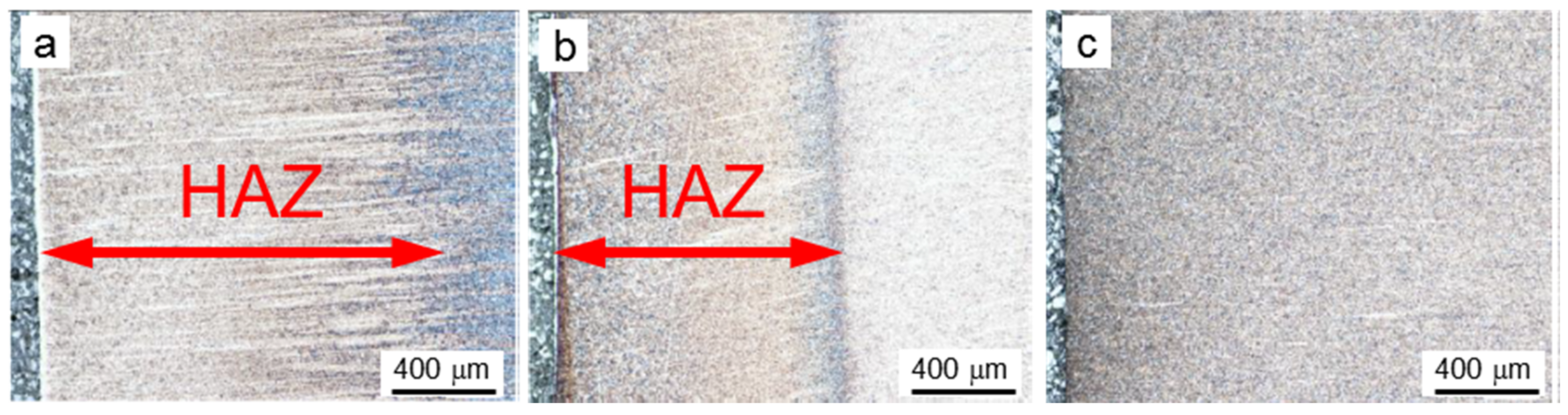
  • With respect to practical aspects of this work, the following may be concluded. In both steels, the maximum decrease in hardness due to thermal cutting with oxy-fuel or plasma may reach 25% of the respective original hardness: 100 HV down from the original 400 HV in the lower alloyed steel with 0.27C-0.40Ti (wt.%) and 130 HV down from the original 500 HV in the more highly alloyed steel with 0.39C-0.60Ti (wt.%). Cutting with oxy-fuel produced a wider heat affected zone (HAZ) (5 and 9 mm for the lower and higher alloyed steels, respectively), compared to plasma cutting (about 3 mm for both steels). No HAZ, microstructure or hardness variation was observed for the water-jet cutting method. Therefore, in practice cutting of Ti-alloyed martensitic steels should be conducted using water-jet. Plasma cutting is acceptable if certain precautions are put in place, in particular a set maximum cutting speed. This would reduce the time of heat effect and potential implications on microstructure and properties.
  • With respect to microstructure-properties variation with steel composition and cutting method, the following fundamental outcomes can be highlighted. Maximum tempering of microstructure (minimum absolute hardness values or maximum relative decrease in hardness associated with the tempering) was observed in the lower alloyed steel (due to weaker solid solution and precipitation strengthening) cut with oxy-fuel (characterised by higher heat input). Minimum tempering occurred in the more highly alloyed steel (due to stronger solid solution and precipitation strengthening) cut with plasma (characterised by lower heat input). In the lower alloyed steel, coarse (TiMoV)(CN), fine Ti-rich and Fe3C dissolved during thermal cutting. In the more highly alloyed steel, both coarse (TiMoV)(CN) and fine Ti-rich particles precipitated and grew, while Fe3C dissolved. These discrepancies in the particle precipitation kinetics can be associated with the variation in steel composition: higher Ti, Mo and C contents in the more highly alloyed steel (and concentrations of these elements in the matrix) increased the solubility temperatures of existing precipitates and the driving force for precipitation and growth of new particles. Precipitation of Ti-rich particles in the more highly alloyed steel during thermal cutting provided precipitation strengthening, which compensated for the softening associated with dislocation annihilation and dissolution of Fe3C.

Author Contributions

Conceptualization, C.R.K., H.L. and D.Y.; Methodology, A.G.K. and M.R.; Investigation, M.R. and A.G.K.; Data Curation, A.G.K. and M.R.; Writing—Original Draft Preparation, A.G.K. and M.R.; Project Administration, C.R.K., H.L. and D.Y.; Funding Acquisition, C.R.K., H.L. and D.Y. All authors have read and agreed to the published version of the manuscript.

Funding

This project was funded through the ARC Research Hub for Australian Steel Manufacturing under the Industrial Transformation Research Hubs scheme (Project ID: IH130100017), together with BlueScope Steel and Bisalloy Steels. The microscopy was carried out using JEOL JSM-7001F FEGSEM (supported by grant LE0882613) and JEOL JEM-2010 TEM (supported by grant LE0237478) microscopes at the Electron Microscopy Centre at the University of Wollongong.

Data Availability Statement

The data presented in this study are available on request from the corresponding author.

Conflicts of Interest

The authors declare no conflict of interest.

References

  1. Xu, L.; Kennon, N.F. A study of the abrasive wear of carbon steels. Wear 1991, 148, 101–112. [Google Scholar] [CrossRef]
  2. Maweja, K.; Stumpf, W. The design of advanced performance high strength low-carbon martensitic armour steels: Microstructural considerations. Mater. Sci. Eng. A 2008, 480, 160–166. [Google Scholar] [CrossRef]
  3. Karagöz, S.; Atapek, Ş.H.; Yilmaz, A. Microstructural and fractographical studies on quenched and tempered armor steels. Materialpruefung 2010, 52, 316–322. [Google Scholar] [CrossRef] [Green Version]
  4. Jena, P.K.; Mishra, B.; Rameshbabu, M.; Babu, A.; Singh, A.K.; Sivakumar, K.; Bhat, T.B. Effect of heat treatment on mechanical and ballistic properties of a high strength armour steel. Int. J. Impact. Eng. 2010, 37, 242–249. [Google Scholar] [CrossRef]
  5. El-Batahgy, A.M.; Miura, T.; Ueji, R.; Fujii, H. Investigation into feasibility of FSW process for welding 1600 MPa quenched and tempered steel. Mater. Sci. Eng. A. 2016, 651, 904–913. [Google Scholar] [CrossRef]
  6. Alexandrov, B.; Theis, K.; Streitenberger, M.; Herold, H.; Martinek, I. Cold cracking in weldments of steel S 690 QT. Weld. World 2005, 49, 64–73. [Google Scholar] [CrossRef]
  7. Magudeeswaran, G.; Balasubramanian, V.; Madhusudhan, R.G. Hydrogen induced cold cracking studies on armour grade high strength, quenched and tempered steel weldments. Int. J. Hydrog. Energy 2008, 33, 1897–1908. [Google Scholar] [CrossRef]
  8. Kuzmikova, L.; Callaghan, M.; Larkin, N.; Scott, R.; DeJong, R.; Li, H.; Norrish, J. A study of a continuous cooling behaviour and effect of preheat and interpass temperature on the HAZ of high strength quenched and tempered steel. In Proceedings of the International Institute of Welding Annual Assembly, Istanbul, Turkey, 15–16 July 2010. paper IX-2352-10. [Google Scholar]
  9. Barenyi, I.; Hires, O.; Liptak, P. Degradation of mechanical properties of armoured steels after its welding. In Proceedings of the International Conference AFASES2011, Brasov, Romania, 26–28 May 2011; pp. 845–848. [Google Scholar]
  10. Kuzmikova, L.; Larkin, N.; Pan, Z.; Callaghan, M.; Li, H.; Norrish, J. Investigation into feasibility of hybrid laser-GMAW process for welding high strength quenched and tempered steel. Aust. Weld. J. 2012, 57, 1–9. [Google Scholar]
  11. Layus, P.; Kah, P.; Khlusova, E.; Orlov, V. Study of the sensitivity of high-strength cold-resistant shipbuilding steels to thermal cycle of arc welding. Int. J. Mech. Mater. Eng. 2018, 13, 3. [Google Scholar] [CrossRef] [Green Version]
  12. Schaupp, T.; Ernst, W.; Spindler, H.; Kannengiesser, T. Hydrogen-assisted cracking of GMA welded 960 MPa grade high-strength steels. Int. J. Hydrog. Energy 2020, 45, 20080–20093. [Google Scholar] [CrossRef]
  13. Balaguru, V.; Balasubramanian, V.; Shivkumar, P. Tensile properties of shielded metal arc welded ultrahigh hard armour steel joints. World J. Adv. Eng. Tech. Sci. 2020, 1, 71–84. [Google Scholar] [CrossRef]
  14. Xu, X.; Xu, W.; Ederveen, F.H.; van der Zwaag, S. Design of low hardness abrasion resistant steels. Wear 2013, 301, 89–93. [Google Scholar] [CrossRef]
  15. Ojala, N.; Valtonen, K.; Heino, V.; Kallio, M.; Aaltonen, J.; Siitonen, P.; Kuokkala, V.T. Effects of composition and microstructure on the abrasive wear performance of quenched wear resistant steels. Wear 2014, 317, 225–232. [Google Scholar] [CrossRef]
  16. Deng, X.; Wang, Z.; Han, Y.; Zhao, H.; Wang, G. Microstructure and abrasive wear behavior of medium carbon low alloy martensitic abrasion resistant steel. J. Iron Steel Res. Int. 2014, 21, 98–103. [Google Scholar] [CrossRef]
  17. Lindroos, M.; Valtonen, K.; Kemppainen, A.; Laukkanen, A.; Holmberg, K.; Kuokkala, V.T. Wear behavior and work hardening of high strength steels in high stress abrasion. Wear 2015, 322–323, 32–40. [Google Scholar] [CrossRef]
  18. Wang, T.S.; Lu, B.; Zhang, M.; Hou, R.J.; Zhang, F.C. Nanocrystallization and martensite formation in the surface layer of medium-manganese austenitic wear-resistant steel caused by shot peening. Mater. Sci. Eng. A 2007, 458, 249–252. [Google Scholar] [CrossRef]
  19. Bregliozzi, G.; Di Schino, A.; Kenny, J.M.; Haefke, H. The influence of atmospheric humidity and grain size on the friction and wear of AISI 304 austenitic stainless steel. Mater. Lett. 2003, 57, 4505–4508. [Google Scholar] [CrossRef]
  20. Abouei, V.; Saghafian, H.; Kheirandish, S.; Ranjbar, K. An investigation of the wear behaviour of 0.2% C dual phase steels. J. Mater. Process. Technol. 2008, 203, 107–112. [Google Scholar] [CrossRef]
  21. Zum Gahr, K.H. Microstructure and Wear of Materials; Elsevier: Amsterdam, The Netherlands, 1987; 559p. [Google Scholar]
  22. Wang, X.; Chen, Y.; Wei, S.; Zuo, L.; Mao, F. Effect of carbon content on abrasive impact wear behavior of Cr-Si-Mn low alloy wear resistant cast steels. Front. Mater. 2019, 6, 153. [Google Scholar] [CrossRef]
  23. Kang, Y.J.; Oh, J.C.; Lee, H.C.; Lee, S. Effects of carbon and chromium additions on the wear resistance and surface roughness of cast high-speed steel rolls. Metall. Mater. Trans. A 2001, 32, 2515–2525. [Google Scholar] [CrossRef] [Green Version]
  24. Bhakat, A.K.; Mishra, A.K.; Mishra, N.S. Characterization of wear and metallurgical properties for development of agricultural grade steel suitable in specific soil conditions. Wear 2007, 263, 228–233. [Google Scholar] [CrossRef]
  25. Tang, L.; Gao, C.; Huang, J.; Zhang, H.; Chang, W. Dry sliding friction and wear behaviour of hardened AISI D2 tool steel with different hardness levels. Tribol. Int. 2013, 66, 165–173. [Google Scholar] [CrossRef]
  26. Parashivamurthy, K.I.; Kumar, R.K.; Seetharamu, S.; Chandrasekharaiah, M.N. Review on TiC reinforced steel composites. J. Mater. Sci. 2001, 36, 4519–4530. [Google Scholar] [CrossRef]
  27. Han, Y.; Shi, J.; Xu, L.; Cao, W.Q.; Dong, H. Effects of Ti addition and reheating quenching on grain refinement and mechanical properties in low carbon medium manganese martensitic steel. Mater. Des. 2012, 34, 427–434. [Google Scholar] [CrossRef]
  28. Kostryzhev, A.G.; Killmore, C.R.; Yu, D.; Pereloma, E.V. Martensitic wear resistant steels alloyed with titanium. Wear 2020, 446–447, 203203. [Google Scholar] [CrossRef]
  29. Zeatoun, L.A.; Morrison, P.W., Jr. Optimizing diamond growth for an atmospheric oxyacetylene torch. J. Mater. Res. 1997, 12, 1237–1252. [Google Scholar] [CrossRef]
  30. Cutting Processes—Application of Oxyfuel Cutting. Available online: https://www.twi-global.com/technical-knowledge/job-knowledge/cutting-processes-application-of-oxyfuel-cutting-050 (accessed on 20 December 2019).
  31. Eyres, D.J. Welding and cutting processes used in shipbuilding. In Ship Construction; Eyres, D.J., Ed.; Butterworth-Heinemann: Oxford, UK, 2007; pp. 75–96. [Google Scholar]
  32. Cutting Processes—Plasma Arc Cutting—Process and Equipment Considerations. Available online: https://www.twi-global.com/technical-knowledge/job-knowledge/cutting-processes-plasma-arc-cutting-process-and-equipment-considerations-051 (accessed on 20 December 2019).
  33. Węglowski, M.S.; Dymek, S.; Kopyściański, M.; Niagaj, J.; Rykała, J.; De Waele, W.; Hertelé, S. A comprehensive study on the microstructure and mechanical properties of arc girth welded joints of spiral welded high strength API X70 steel pipe. Arch. Civ. Mech. Eng. 2020, 20, 14. [Google Scholar] [CrossRef] [Green Version]
  34. Shi, L.; Alexandratos, S.A.; O’Dowd, N.P. Combined finite element and phase field method for simulation of austenite grain growth in the heat-affected zone of a martensitic steel weld. Proc. Inst. Mech. Eng. Part L J. Mater. Des. Appl. 2019, 233, 13–27. [Google Scholar] [CrossRef] [Green Version]
  35. Garcin, T.; Militzer, M.; Poole, W.J.; Collins, L. Microstructure model for the heat-affected zone of X80 linepipe steel. Mater. Sci. Technol. 2016, 32, 708–721. [Google Scholar] [CrossRef]
  36. El-Faramawy, H.S.; Ghali, S.N.; Eissa, M.M. Effect of titanium addition on behavior of medium carbon steel. J. Miner. Mater. Charact. Eng. 2012, 11, 108–1112. [Google Scholar] [CrossRef]
  37. Strid, J.; Easterling, K.E. On the chemistry and stability of complex carbides and nitrides in microalloyed steels. Acta Metall. 1985, 33, 2057–2074. [Google Scholar] [CrossRef]
  38. Dobrzanski, L.A.; Zarychta, A.; Ligarski, M. High-speed steels with addition of niobium or titanium. J. Mater. Process. Tech. 1997, 63, 531–541. [Google Scholar] [CrossRef]
  39. Soto, R.; Saikaly, W.; Bano, X.; Issartel, C.; Rigaut, G.; Charai, A. Statistical and theoretical analysis of precipitates in dual-phase steels microalloyed with titanium and their effect on mechanical properties. Acta Mater. 1999, 47, 3475–3481. [Google Scholar] [CrossRef]
  40. Yu, W.T.; Li, J.; Shi, C.B.; Zhu, Q.T. Effect of titanium on the microstructure and mechanical properties of high-carbon martensitic stainless steel 8Cr13MoV. Metals 2016, 6, 193. [Google Scholar] [CrossRef] [Green Version]
  41. Bhadeshia, H.K.D.H.; Honeycombe, S.R. Steels: Microstructure and Properties, 3rd ed.; Butterworth-Heinemann: Oxford, UK, 2006; pp. 183–208. [Google Scholar]
  42. Krauss, G. Tempering of lath martensite in low and medium carbon steels: Assessment and challenges. Steel Res. Int. 2017, 88, 1700038. [Google Scholar] [CrossRef]
  43. Pawłowski, B. Critical points of hypoeutectoid steel—Prediction of the pearlite dissolution finish temperature Ac1f. J. Achiev. Mater. Manuf. Eng. 2011, 49, 331–337. [Google Scholar]
  44. Trzaska, J.; Dobrzanski, L.A. Modelling of CCT diagrams for engineering and constructional steels. J. Mater. Process. Technol. 2007, 192–193, 504–510. [Google Scholar] [CrossRef]
  45. Lu, Q.; Xu, W.; van der Zwaag, S. Designing new corrosion resistant ferritic heat resistant steel based on optimal solid solution strengthening and minimisation of undesirable microstructural components. Comp. Mater. Sci. 2014, 84, 198–205. [Google Scholar] [CrossRef]
  46. Kong, J.; Xie, C. Effect of molybdenum on continuous cooling bainite transformation of low-carbon microalloyed steel. Mater. Des. 2006, 27, 1169–1173. [Google Scholar] [CrossRef]
  47. Hu, H.; Xu, G.; Zhou, M.; Yuan, Q. Effect of Mo content on microstructure and property of low-carbon bainitic steels. Metals 2016, 6, 173. [Google Scholar] [CrossRef] [Green Version]
  48. Mukherjee, S.; Timokhina, I.; Zhu, C.; Ringer, S.P.; Hodgson, P.D. Clustering and precipitation processes in a ferritic titanium-molybdenum microalloyed steel. J. Alloys Compd. 2017, 690, 621–632. [Google Scholar] [CrossRef]
  49. Dhara, S.; Marceau, R.K.W.; Wood, K.; Dorin, T.; Timokhina, I.B.; Hodgson, P.D. Precipitation and clustering in a Ti-Mo steel investigated using atom probe tomography and small-angle neutron scattering. Mater. Sci Eng. A 2018, 718, 74–86. [Google Scholar] [CrossRef]
  50. Chen, C.Y.; Yang, J.R.; Chen, C.C.; Chen, S.F. Microstructural characterization and strengthening behavior of nanometer sized carbides in Ti–Mo microalloyed steels during continuous cooling process. Mater. Charact. 2016, 114, 18–29. [Google Scholar] [CrossRef]
  51. Kostryzhev, A.G.; Marenych, O.O. New technology to produce 1 GPa low carbon microalloyed steels from cast strip. Metals 2018, 8, 662. [Google Scholar] [CrossRef] [Green Version]
  52. Zhang, K.; Li, Z.D.; Sun, X.J.; Yong, Q.L.; Yang, J.W.; Li, Y.M.; Zhao, P.L. Development of Ti–V–Mo complex microalloyed hot-rolled 900MPa grade high strength steel. Acta Metall. Sin. 2015, 28, 641–648. [Google Scholar] [CrossRef] [Green Version]
  53. Wang, Z.; Zhang, H.; Guo, C.; Liu, W.; Yang, Z.; Sun, X.; Zhang, Z.; Jiang, F. Effect of molybdenum addition on the precipitation of carbides in the austenite matrix of titanium micro-alloyed steels. J. Mater. Sci. 2016, 51, 4996–5007. [Google Scholar] [CrossRef]
  54. Tingaev, A.K.; Gubaydulin, R.G.; Ilin, I.A. Study of the effect of thermal cutting on the microstructure and chemical composition of the edges of workpieces made of steel brands S345, S390. Procedia Eng. 2016, 150, 1783–1790. [Google Scholar] [CrossRef] [Green Version]
  55. Ilin, I.A.; Krasnoperova, A.A.; Sirotkin, E.A. Effect study of thermal cutting methods on the edge’s microstructure of high-strength steel grade S700MC. Mater. Sci. Forum 2019, 946, 928–933. [Google Scholar] [CrossRef]
  56. Pawar, S.S.; Inamdar, K.H. Analysis of heat affected zone in plasma arc cutting of SS 316L plates. Int. J. Innov. Res. Sci. Eng. Technol. 2017, 6, 8160–8165. [Google Scholar]
  57. Gustafson, A. Coarsening of TiC in austenitic stainless steel–Experiments and simulations in comparison. Mater. Sci Eng. A. 2000, 287, 52–58. [Google Scholar] [CrossRef]
  58. Jones, A.R.; Ralph, B. Growth and dissolution of NbC particles in an austenitic stainless steel. Metallography 1977, 10, 469–480. [Google Scholar] [CrossRef]
  59. Gong, P.; Palmiere, E.J.; Rainforth, W.M. Dissolution and precipitation behaviour in steels microalloyed with niobium during thermomechanical processing. Acta Mater. 2015, 97, 392–403. [Google Scholar] [CrossRef]
  60. Morral, J.E.; Purdy, G.R. Particle coarsening in binary and multicomponent alloys. Scr. Metall. Mater. 1994, 30, 905–908. [Google Scholar] [CrossRef]
  61. Papaefthymiou, S.; Bouzouni, M.; Gavalas, E. Theoretical study of particle dissolution during homogenization in Cu–Fe–P alloy. Metals 2018, 8, 455. [Google Scholar] [CrossRef] [Green Version]
  62. Abe, F.; Murata, M.; Miyazaki, H. Effect of TiC and NbC carbides on creep life of stainless steels. Mater. High Temp. 2019, 36, 35–47. [Google Scholar] [CrossRef]
Figure 1. Optical microscopy images of heat affected zone in Steel H cut with (a) oxy-fuel, (b) plasma, and (c) water-jet.
Metals 11 01138 g001
Figure 2. Hardness profiles at the plate mid-thickness position for (ac) Steel L and (df) Steel H cut with (a,d) oxy-fuel, (b,e) plasma and (c,f) water-jet; each point on the hardness profiles is the mean value of 5 indentations made through plate thickness.
Metals 11 01138 g002
Figure 3. SEM images of grain structure in Steels L and H cut using oxy-fuel cutting method: left to right, at the cut edge, point of minimum HV, and far away from the cut edge (base plate).
Metals 11 01138 g003
Figure 4. SEM images of grain structure in Steels L and H cut using plasma cutting method: left to right, at the cut edge, point of minimum HV, and far away from the cut edge (base plate).
Metals 11 01138 g004
Figure 5. SEM-EDS maps of coarse particles in Steels (a) L and (b) H from selected locations.
Metals 11 01138 g005aMetals 11 01138 g005b
Figure 6. Optical images of Steel L and Steel H cut with the three studied methods (un-etched samples).
Metals 11 01138 g006
Figure 7. Coarse (TiMoV)(CN) particle number density distributions at 0.5 mm position from the cut edge in Steels (a) L and (b) H, for the samples cut with oxy-fuel in Steels (c) L and (d) H, and for the samples cut with plasma in Steels (e) L and (f) H; arrows in (a,b) indicate the directions of distributions peaks shift for oxy-fuel and plasma cutting methods with respect to the distribution observed for the water jet cutting, and these in (cf) indicate the directions of distributions peaks shift for 0.5/2.0/3.0/1.5 mm positions with respect to the distribution for the 10 mm position.
Metals 11 01138 g007
Figure 8. SEM-EDS maps of fine particles observed in both steel grades.
Metals 11 01138 g008
Figure 9. SEM images of fine precipitates in Steels L and H cut using oxy-fuel cutting method: left to right, at the cut edge, point of minimum HV, and far away from the cut edge (base plate).
Metals 11 01138 g009
Figure 10. SEM images of fine precipitates in Steels L and H cut using plasma cutting method: left to right, at the cut edge, point of minimum HV, and far away from the cut edge (base plate).
Metals 11 01138 g010
Figure 11. Fine Ti-rich particle number density distributions at 0.5 mm position from the cut edge for Steels (a) L and (b) H, for the samples cut with oxy-fuel for Steels (c) L and (d) H, and for the samples cut with plasma in Steels (e) L and (f) H; arrows in (a,b) indicate the directions of distributions peaks shift for oxy-fuel and plasma cutting methods with respect to the distribution observed for the water jet cutting, and these in (cf) indicate the directions of distributions peaks shift for 0.5/2.0/3.0/1.5 mm positions with respect to the distribution for the 10 mm position.
Metals 11 01138 g011
Figure 12. Fe3C particles in the base metal of Steel L: (a,b) SEM image with the corresponding EDS carbon map; (c,d) bright and dark field TEM images; (e) diffraction pattern corresponding to images (c,d); and (f) indexing of the diffraction pattern shown in (e).
Metals 11 01138 g012
Figure 13. Fe3C particle number density distributions at 0.5 mm position from the cut edge in Steel (a) L and (b) H; arrows in (a,b) indicate the directions of distributions peaks shift for oxy-fuel and plasma cutting methods with respect to the distribution observed for the water jet cutting, and these in (cf) indicate the directions of distributions peaks shift for 0.5/2.0/3.0/1.5 mm positions with respect to the distribution for the 10 mm position.
Metals 11 01138 g013
Table 1. Chemical composition of steels studied in this project (wt.%).
Steel TypeCSiMnCrMoNiTiV
Steel L0.270.370.710.850.240.0220.400.01
Steel H0.390.831.280.680.330.460.600.01
Table 2. Average grain size in the studied steels.
Steel Grade/Cutting MethodSteel LSteel H
Oxy-Fuel
Position from cut edge0.5 mm2.0 mm10 mm0.5 mm3.0 mm10 mm
Average size, µm2.3 ± 0.21.9 ± 0.12.3 ± 0.23.0 ± 0.22.1 ± 0.12.5 ± 0.3
Plasma
Position from cut edge0.5 mm1.5 mm10 mm0.5mm1.5mm10 mm
Average size, µm2.4 ± 0.22.5 ± 0.22.4 ± 0.22.3 ± 0.22.6 ± 0.12.5 ± 0.2
Water-Jet
Position from cut edge0.5 mm and 10 mm0.5 mm and 10 mm
Average size, µm2.6 ± 0.22.5 ± 0.2
Table 3. Average parameters of coarse (TiMoV)(CN) particles studied with optical microscopy (at 10 mm away from the cut edge no heat effect was observed, therefore the microstructure at this position was considered as the as-received).
Steel Grade/Cutting MethodSteel LSteel H
Oxy-Fuel
Position from cut edge0.5 mm2.0 mm10 mm0.5 mm3.0 mm 10 mm
Average size, µm1.6 ± 0.72.5 ± 0.51.8 ± 0.62.9 ± 1.22.2 ± 0.82.9 ± 0.9
Number density, µm−20.00200.00120.00210.00390.00250.0016
Plasma
Position from cut edge0.5 mm1.5 mm10 mm0.5 mm1.5 mm 10 mm
Average size, µm1.9 ± 0.41.5 ± 0.52.1 ± 0.72.5 ± 0.53.2 ± 1.32.8 ± 0.8
Number density, µm−20.00210.00110.00200.00330.00210.0017
Water-Jet
Position from cut edge0.5 mm10 mm0.5 mm10 mm
Average size, µm2.0 ± 0.71.8 ± 0.62.8 ± 0.82.8 ± 1.0
Number density, µm−20.00200.00190.00170.0017
Table 4. Average parameters of fine Ti-rich particles studied with SEM (at 10 mm away from the cut edge no heat effect was observed, therefore the microstructure at this position was considered as the as-received).
Steel Grade/Cutting MethodSteel LSteel H
Oxy-Fuel
Position from cut edge0.5 mm 2.0 mm 10 mm0.5 mm 3.0 mm 10 mm
Average size, nm112 ± 2193 ± 3082 ± 26162 ± 50104 ± 42144 ± 48
Number density, µm−21.12.21.30.40.80.3
Plasma
Position from cut edge0.5 mm 1.5 mm 10 mm0.5 mm 1.5 mm10 mm
Average size, nm135 ± 3485 ± 2883 ± 23153 ± 45210 ± 56150 ± 43
Number density, µm−20.80.51.40.60.60.3
Table 5. Average parameters of fine Fe3C particles studied with SEM (at 10 mm away from the cut edge no heat effect was observed, therefore the microstructure at this position was considered as the as-received).
Steel Grade/Cutting MethodSteel LSteel H
Oxy-Fuel
Position from cut edge0.5 mm 2.0 mm 10 mm 0.5 mm 3.0 mm 10 mm
Average size, nm37 ± 947 ± 1049 ± 1152 ± 968 ± 1245 ± 10
Number density, µm−22.01.12.30.50.61.4
Plasma
Position from cut edge0.5 mm 1.5 mm 10 mm0.5 mm 1.5 mm 10 mm
Average size, nm60 ± 1167 ± 958 ± 849 ± 1051 ± 1153 ± 10
Number density, µm−22.21.52.41.01.21.3
Table 6. Correlation of the microstructural parameters and hardness to steel grade and cutting method.
Steel Grade/Cutting MethodSteel LSteel H
Oxy-Fuel
Position from cut edge0.5 mm 2.0 mm 10 mm 0.5 mm 3.0 mm 10 mm
Average grain size, µm2.3 ± 0.21.9 ± 0.12.3 ± 0.23.0 ± 0.12.1 ± 0.12.5 ± 0.3
Number density, µm−2Coarse Ti-rich0.00200.00120.00210.00390.00250.0016
Fine Ti-rich1.12.21.30.40.80.3
Fe3C2.01.12.30.50.61.4
Hardness, HV430 ± 8300 ± 5410 ± 10520 ± 10359 ± 7500 ± 4
Plasma
Position from cut edge0.5 mm 1.5 mm 10 mm 0.5mm 1.5mm 10 mm
Average grain size, µm2.4 ± 0.22.5 ± 0.22.4 ± 0.22.3 ± 0.22.6 ± 0.12.5 ± 0.2
Number density, µm−2Coarse Ti-rich0.00210.00110.00200.00330.00210.0017
Fine Ti-rich0.80.51.40.60.60.3
Fe3C2.21.52.41.01.21.3
Hardness, HV400 ± 8300 ± 5385 ± 6530 ± 4417 ± 4505 ± 5
Publisher’s Note: MDPI stays neutral with regard to jurisdictional claims in published maps and institutional affiliations.

