Article

Sub-Microstructure of Surface and Subsurface Layers after Electrical Discharge Machining Structural Materials in Water

by
Sergey N. Grigoriev
1,
Marina A. Volosova
1,
Anna A. Okunkova
1,*,
Sergey V. Fedorov
1,
Khaled Hamdy
1,2 and
Pavel A. Podrabinnik
1
1
Department of High-Efficiency Processing Technologies, Moscow State University of Technology “STANKIN”, Vadkovsky per. 1, 127055 Moscow, Russia
2
Production Engineering and Mechanical Design Department, Faculty of Engineering, Minia University, Minia 61519, Egypt
*
Author to whom correspondence should be addressed.
Metals 2021, 11(7), 1040; https://doi.org/10.3390/met11071040
Submission received: 31 May 2021 / Revised: 24 June 2021 / Accepted: 25 June 2021 / Published: 29 June 2021

Abstract

:
The material removal mechanism, submicrostructure of surface and subsurface layers, nanotransformations occurred in surface and subsurface layers during electrical discharge machining two structural materials such as anti-corrosion X10CrNiTi18-10 (12kH18N10T) steel of austenite class and 2024 (D16) duralumin in a deionized water medium were researched. The machining was conducted using a brass tool of 0.25 mm in diameter. The measured discharge gap is 45–60 µm for X10CrNiTi18-10 (12kH18N10T) steel and 105–120 µm for 2024 (D16) duralumin. Surface roughness parameters are arithmetic mean deviation (Ra) of 4.61 µm, 10-point height (Rz) of 28.73 µm, maximum peak-to-valley height (Rtm) of 29.50 µm, mean spacing between peaks (Sm) of 18.0 µm for steel; Ra of 5.41 µm, Rz of 35.29 µm, Rtm of 43.17 µm, Sm of 30.0 µm for duralumin. The recast layer with adsorbed components of the wire tool electrode and carbides was observed up to the depth of 4–6 µm for steel and 2.5–4 µm for duralumin. The Levenberg–Marquardt algorithm was used to mathematically interpolate the dependence of the interelectrode gap on the electrical resistance of the material. The observed microstructures provide grounding on the nature of electrical wear and nanomodification of the obtained surfaces.

1. Introduction

Electrical discharge machining is known technology of changing shape and size conductive and non-conductive materials [1,2,3,4]. Despite plenty of works devoted to the research of electrical discharge machining parameters optimization [5,6,7], there is almost no works devoted to the effect of electrical discharge machining on surface and subsurface layers of structural materials, in particularity to anti-corrosion steels of austenite class [1,8] and aluminum alloy (2024) [9,10].
The thickness of recast layer depending on die-sinking electrical discharge machining factors was researched for tool-, forming medium carbon steel SKD-61 (X40CrMoV5-1) with a copper tool electrode in [11]. The minimum recast layer thickness of 3.72 µm was achieved at operational current of 1 A and operational voltage of 30 V when time of pulse on and time of pulse off were of 50 and 12 µs correspondingly. The authors, in their work, recklessly propose to remove the layer after electrical discharge machining without setting themselves tasks concerning the specific application of the final product. However, an eroded layer with a surface type can be a definite advantage for some applications [12,13,14]:
  • It creates a pleasant tactile texture of evenly distributed convexes of injection-molding plastic parts such as computer cases or other housings.
  • The formed eroded layer contributes to reduced surface wear due to its improved exploitation properties (microhardness, wear resistance).
  • The convexed surface favors the removal of injection-molded plastic products from the mold.
The surface layer of tool AISI H13 steel (SKD-61, X40CrMoV5-1) after die-sinking electrical discharge machining with a copper tool electrode was improved (microhardness) by adding nitrogen-containing components into a deionized water medium [15]. The formed nitrides and recast layers were detected at the minimum depth of 31.0 ± 4.6 μm with pulse time on and off equal to 100 µs, correspondingly. The maximum depth was 53.2 ± 5.5 μm at pulse time on and off of 500 µs. The microhardness of the surface layer was 800–920 HV0.025 (the maximum value corresponds to pulse time on of 100 µs, pulse time off of 150–203 µs). The hardness dramatically decreases up to the value of 280–390 HV0.025 at a depth of 12 µm.
The research of hot work Cr12 (X200Cr12, SKD1) steel recast layer after electrical discharge machining in a hydrocarbon medium with a copper tool electrode showed that the thickness of the recast layer is constant at a pulse duration of 200–300 µs and copper of tool electrode concentration grows [16]. The solidified submcrostructure of surface and subsurface layers was defined as a dense and fine dendritic outermost sublayer, a coarse dendritic intermediate sublayer, and an innermost. The predominant chemical composition of the surface and subsurface layers contains (Fe,Mn)3AlC carbide, which shows the carbonization of the layers due to the decomposition of the dielectric medium and the precipitation of carbides, which increased the microhardness of the surface to 574 HV.
Wire electrical discharge machining of Ni-Cu alloy (67% Ni–23% Cu, Monel 400) showed the formed recast layer of 2.55 µm [17]. The surface layer’s microhardness was 172–220 HV and increased steadily up to the depth of 20 µm up to 260–275 HV values.
Thus, surface and subsurface layers’ parameters and submicrostructure research for the wide range of structural materials is an actual scientific and technical problem. Some popular structural materials—especially anti-corrosion steels of austenite and martensitic classes, non-ferrous, and aluminum alloys in particular—required more attention to predict their properties in the conditions of real exploitation and were not covered by previously conducted studies.
The study aims to research the physical nature of wear and phenomena of electrical discharge machining of two structural materials with a brass wire tool electrode in a water medium in the conditions of electrical discharge wear, classification of wear, and observed defects, nanomodification of machined surfaces through optic and scanning electron microscopy, spectroscopy, surface roughness parameters, and discharge gap. The conducted work improves understanding of electrical discharge machining of conductive and non-conductive materials to predict the parameters of surface and near-surface layers of machined surfaces. Based on previously conducted studies, deionized water was chosen as a dielectric medium [18]:
  • to exclude the influence of specimens’ carbonization due to working liquid decomposition under discharge pulses;
  • to avoid the formation of explosives in the presence of water or hydrogen, such as aluminum carbide, during electrical discharge machining specimens in hydrocarbons.
The scientific novelty of the work is in the new data on physical phenomena that occurred between electrodes and water medium in the presence of plasma heat, classification of the obtained machined surface defects, new data on nanomodification of the machined surfaces, interpolation model of the obtained dependencies of the discharge gap on electrical properties of the material. The practical significance of the work is developing the scheme of surface and subsurface layers’ structure that is used for engineering work to predict the behavior of the layers under the load.
The tasks of the study are the research of the surface topology of two structural materials, such as austenite anti-corrosion X10CrNiTi18-10 (12kH18N10T) steel and AA2024 (D16) duralumin, after wire electrical discharge machining with a brass wire tool electrode in a water medium, discharge gap, classification of the observed surface defects, traces of destruction, and research of the chemical content of surface and subsurface layers (Figure 1).

2. Materials and Methods

2.1. Equipment and Machining Factors

A two-axis wire electrical discharge machine ARTA 123 Pro (JSC “Scientific Industrial Corporation “Delta-Test”, Fryazino, Moscow Oblast, Russia) (Table 1, Figure 2) was chosen in the experiments for machining in deionized water. The machine body is made of gray cast iron that showed excellent thermal and compensating vibration properties.
The machine is placed in a thermo-constant room to reduce ambient temperature influence on the experimental results. The specimens were immersed in deionized water for 10 min before electrical discharge machining to avoid dimensional fluctuations of the temperature difference between the environment and the working medium. The level of the medium was established at 1–2 mm above workpiece height. The upper wire tool guide was established above 2–5 mm from the dielectric level [19,20]. The wire tool electrode was made of CuZn35 brass with a diameter dw of 0.25 mm, Artacut (JSC “Scientific Industrial Corporation “Delta-Test”, Fryazino, Moscow Oblast, Russia), with a tensile strength of 1000 N/mm2. The computer numerical control (CNC) program was prepared manually. The first set of experiment factors were chosen following recommendations [21,22,23] and experience in machining structural materials (Table 2). The electrode tool has a negative bias, and a workpiece is positive. Electrical discharge machining was accomplished with flushing to provide better performance and machining stability [24]. The path offset was not taken into account during machining [1,21].

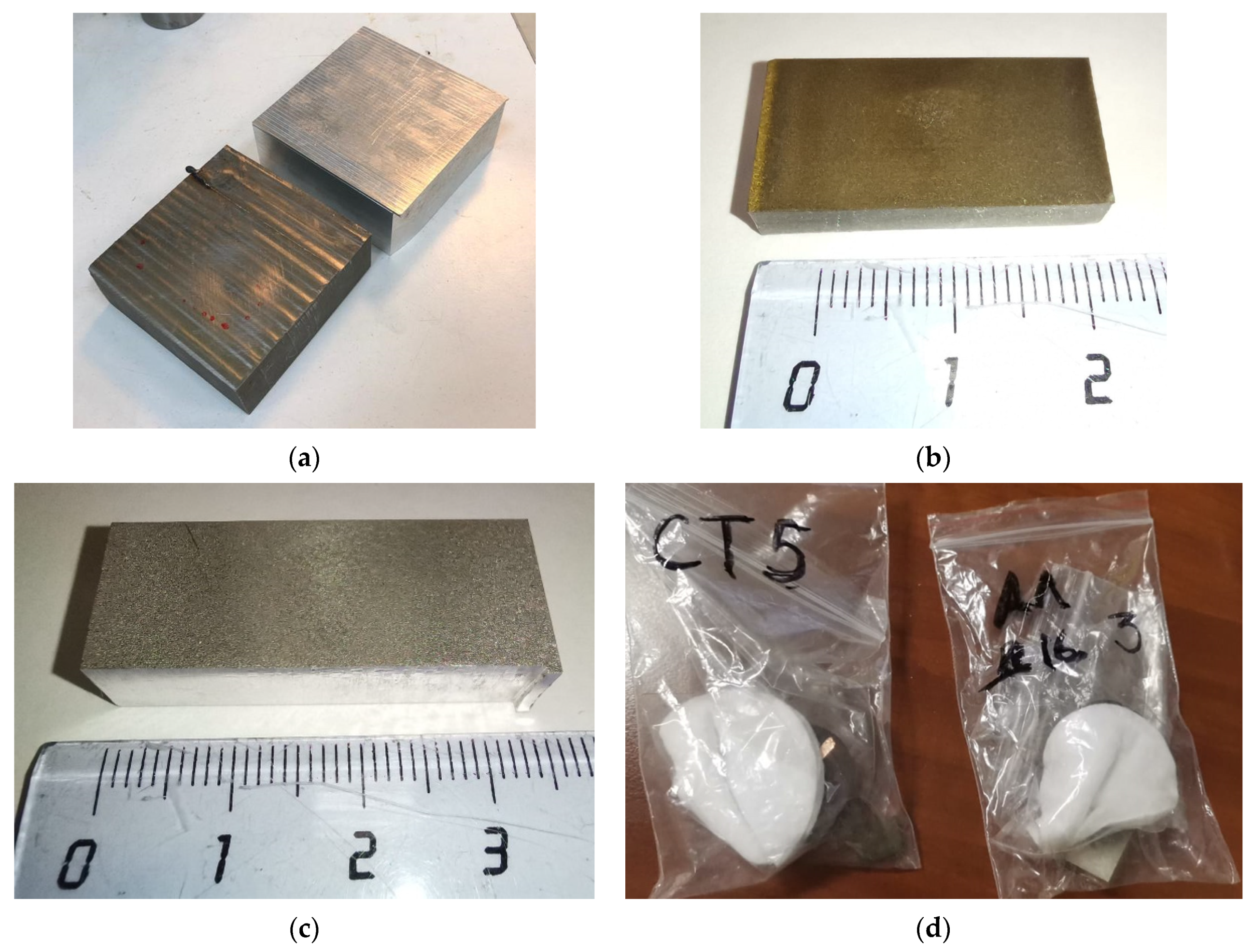
2.2. Materials to Be Machined

Two structural materials typical for the aerospace industry and tool production were chosen for the experiments, such as anticorrosion chrome-nickel X10CrNiTi18-10 (12kH18N10T) steel of austenite class (Table 3) and 2024 duralumin (D16, Table 4). The thickness of the samples was 20 mm (Figure 3a). Five samples for each experimental set were produced to research a machined surface and measure the discharge gap (Figure 3b,c). It should be noted that chromium content provides anticorrosion properties of the steel when nickel is responsible for its austenite class that improves its machinability and extends the exploitation properties. The titanium addition hampers chromium carbides’ formation and forms refractory carbides of titanium in reaction with carbon. This type of chromium-nickel steel dominates the modern rolled metal market [25,26,27,28]. Duralumin is used mainly in a quenched state and is classified as a durable thermo-hardened construction material for the aerospace industry and unsuitable for welding [29,30].
A Fischer Sigmascope SMP10 instrument (Helmut Fischer GmbH, Sindelfingen, Germany) controlled the specific electrical resistance ρ (Figure 3d, Table 5). The device measures the material electric conductance in Siemens and the percentage of the control sample’s electrical conductance made of annealed bronze in the range of 1–112%. The measured values are converted to Ω mm 2 m . The linear thermal expansion coefficient, thermal conductivity, melting points are presented in Table 5 [31,32,33,34].

2.3. Characterization of the Samples

The surface roughness parameters such as arithmetic mean deviation (Ra), 10-point height (Rz), maximum peak-to-valley height (Rtm), mean spacing between peaks (Sm) of the surface samples were controlled by a high-precision profilometer, Hommel Tester T8000 (Jenoptik GmbH, Villingen-Schwenningen, Germany), with a resolution of 1–1000 nm; a measurement error is of 2%.
The Dektak XT stylus profilometer (Bruker Nano, Inc., Billerica, MA, USA) obtained linear and 3D diagrams with a vertical accuracy of 5 Å (0.5 nm), the radius of the stylus is 12.5 µm.
The cross-sections were prepared using Opal 410, Jade 700, and Saphir 300 sample equipment (ATM, Haan, The Netherlands) and the standard probe techniques. An epoxy resin with quartz sand provided pouring of the samples as a filler was used.
The optical microscopy was provided by an Olympus BX51M instrument (Ryf AG, Grenchen, Switzerland). A VEGA 3 LMH instrument (Tescan Brno s.r.o., Brno, The Czech Republic) magnifies up to 1,000,000× provided scanning electron microscopy (SEM) and energy dispersive spectroscopy (EDS).
X-ray photoelectron spectroscopy (XPS) was used to study the chemical composition of subsurface layers. The analysis was performed using Thermo Scientific’s K-ALPHA X-ray photoelectron spectrometer (Thermo Fisher Scientific Inc., Bremen, Germany) equipped with an Avantage Data System (version 5.0).
The discharge gap is calculated by the next equations [8,35]
Δ D B = l d w 2 ,
where Δ is a measured distance of the cut between two machined surfaces, mm; dw is a diameter of the wire tool, mm. The effective (recommended) offset of the wire tool electrode path is calculated by the equation
Δ * D B = Δ D B d w 2 = l 2
The Levenberg—Marquardt algorithm (increasing exponential approximation and Boltzmann (Sigmoidal) approximation over a dataset) [36], which is an optimization method aimed at solving the least-squares problems and an alternative to Newton’s method, was used to mathematically interpolate the dependence of the interelectrode gap on the electrical resistance of the material. SciDAVis 2.4.0 (Scientific Data Analysis and Visualization, Slashdot Media, San Diego, CA, USA) software was used to interpolate and analyze the obtained dependencies.

3. Results

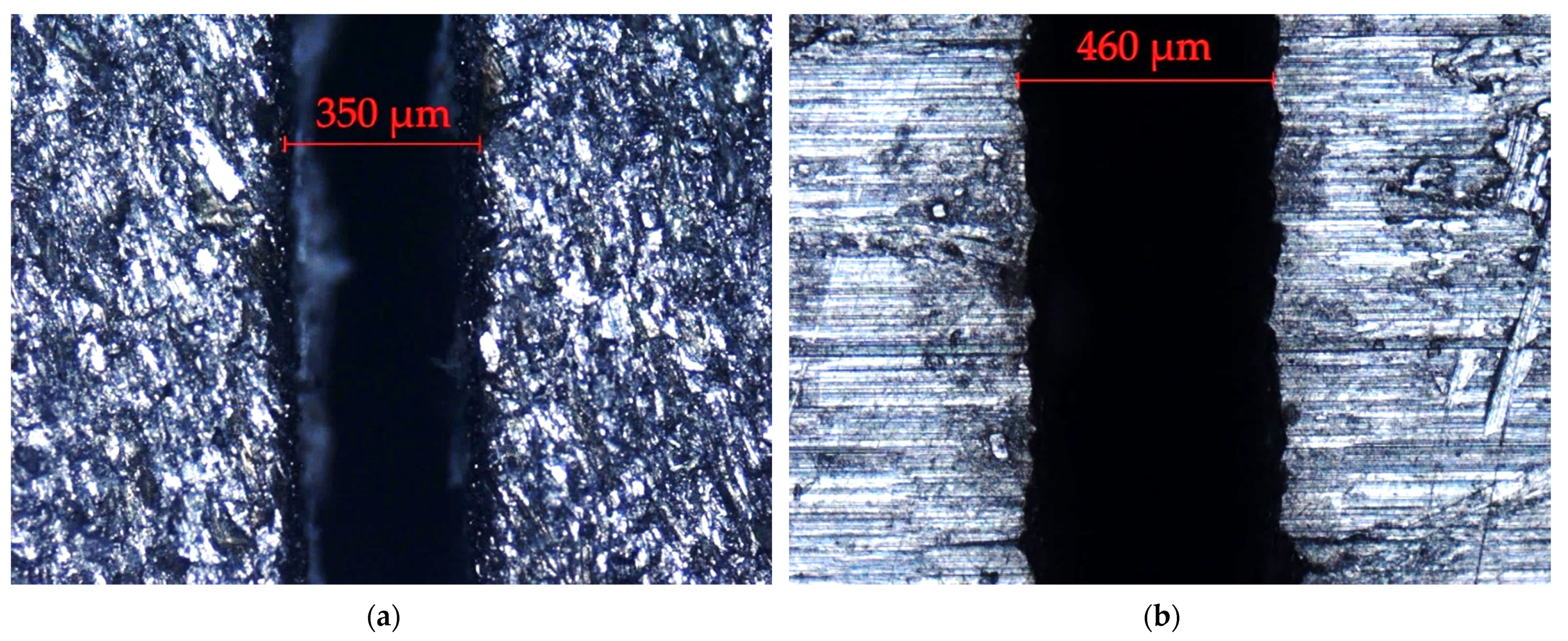
3.1. Machining Factors and the Discharge Gap

The stable machining process was achieved, but the wire consumption exceeds the expected value during the first set of experiments for X10CrNiTi18-10 (12kH18N10T) steel. The wire rewinding speed was reduced by 30% during the second group of experiments. Electrical discharge machining 2024 (D16) duralumin showed that the wire is broken, and no effective discharges were achieved. The second group of the experiments showed a stable processing character with increased operational voltage and rewinding speed combined with shortened pulses.
Figure 4 shows the measured slot width l for two types of materials, including the wire radius dw of 0.25 mm. The effective discharge gap ΔDB following Equation (1) is in the range of 45–60 µm for X10CrNiTi18-10 (12kH18N10T) steel and the range of 105–120 µm for 2024 (D16) duralumin. The minimal value is associated with a stable mode. The recommended value for the offsets of the wire tool path Δ*DB will be 175 µm and 235 µm correspondingly.
Optical microscopy of the formed kerf on the X10CrNiTi18-10 (12kH18N10T) steel specimen shows the absence of fused layers of the kerf edge, a uniform distribution of the workpiece texture (Figure 4a). The edges of the kerf on the duralumin specimen demonstrate increased roughness, possibly indirectly related to the high electrical conductivity of aluminum, which means more intense and dense radial channels between the electrodes, increased machining productivity at roughing (Figure 4b).

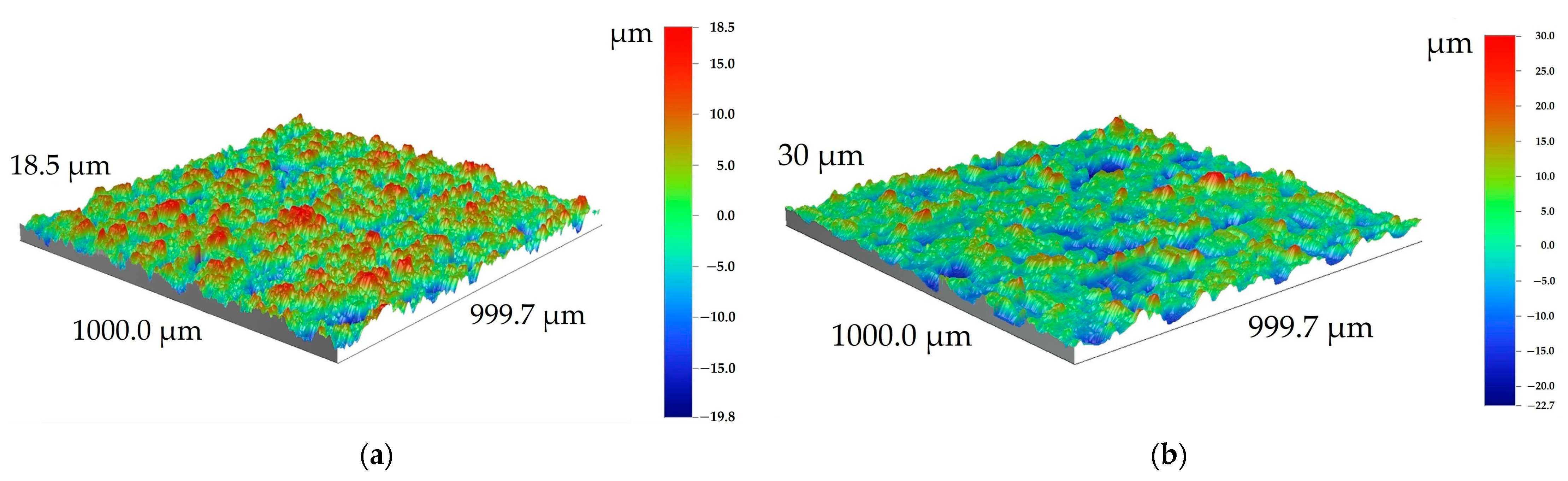
3.2. Roughness Parameters and Surface Topology

3D profiles of the machined surfaces are in Figure 5, and measured roughness parameters are in Table 6. Both samples have a typical “shagreen” type of surface with the spaced convexes of deposed recast (secondary) material. The formed flakes of secondary material are up to 35 µm for X10CrNiTi18-10 (12kH18N10T) steel and up to 45 µm for 2024 (D16) duralumin. The size of flakes strongly depends on the electrical conductivity of materials and used electrical factors of machining (higher voltage corresponds to more profound geometry when operational current is responsible for the density of discharge and, consequently, erosion wells). The obtained profiles are further discussed in Section 4.2.

3.3. Characterization of the Samples

The machined surfaces have the following defects–mechanical rupture (1) occurred at the end of the operation and thermal traces of short circuits (2) (Figure 6).
The SEM-images of the eroded surfaces at the place of wire tool penetration demonstrate three types of defects related to the thermal chemical nature of the material destruction that occurred during electrical discharge machining–thermal cracks formed during cooling the deposed material of secondary structure (1), flakes of the secondary structure formed from the components of the electrodes and dielectric medium (2), main recast and the heat-affected sublayer of primary material (3) (Figure 7). The obtained eutectics are further discussed in Section 4.2.

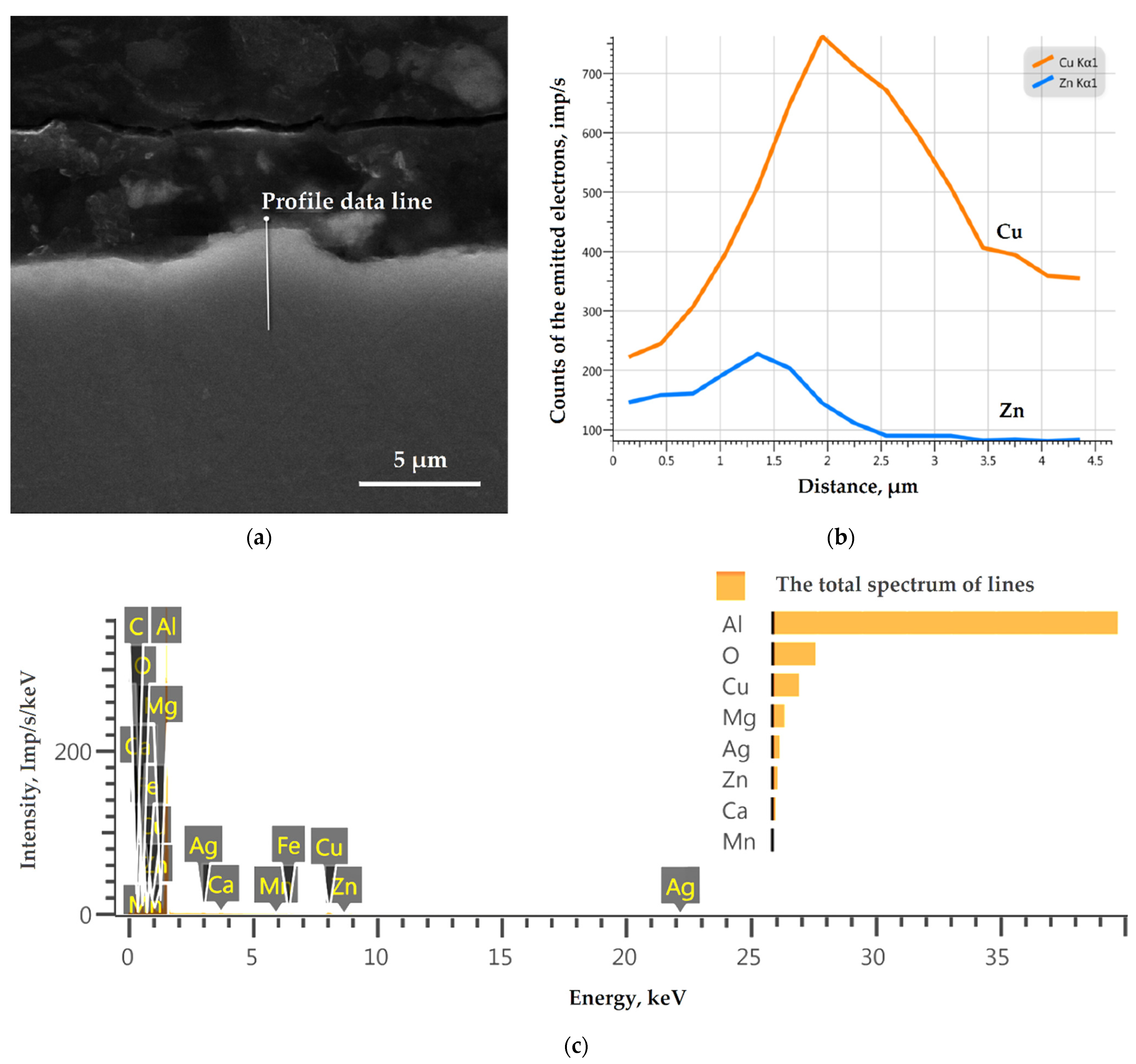
3.4. Chemical Nanomodification of the Surface Layer

The chemical analyses of the sample surface after electrical discharge machining by X-ray photoelectron spectroscopy are presented in Figure 8 and Figure 9. Both of the surface layers have the presence of the chemical components of the wire tool and complex compounds of secondary order (metastable solid solution and/or eutectics).
Both samples show metallic Zn and copper oxide samples responsible for metallic grey and black sediment on the machined surfaces (Figure 8a,b and Figure 9a,b). Zn is bound in oxide (usually matte white film) (Figure 9a) at the duralumin sample. The quantity analyses confirmed their slight presence of wire tool electrode material (less than 4 at %).
X10CrNiTi18-10 (12kH18N10T) steel sample also demonstrates slight (less than 3 at %) presence of Fe₂O₃ and Cr₂O₃ oxides (Figure 8c,d), when 2024 (D16) duralumin sample (Figure 9c,d) is covered with Al₂O₃ film (10.42 at %) of the primary material.
C-C, C-O, C=O (Figure 8f and Figure 9e) bonds correspond to the atmospheric contamination and precipitation of carbides during directed rapid heating and slow cooling (typical for welding, plasma or laser treatment). For the samples of X10CrNiTi18-10 (12kH18N10T) steel, it is ~58 at % and, for the samples of 2024 (D16) duralumin, it is ~40 at %.

3.5. Nanomodification (Elemental Analysis) of the Subsurface Layers

Figure 10 shows the cross-sectional surface of an X10CrNiTi18-10 (12kH18N10T) steel sample to research the near-surface layers’ chemical composition and distribution spectrum of the chemical elements in the near-surface layers of the sample. The near-surface layer has recast material presence and formed flakes of secondary material (solid solutions and eutectics) and cracks (Figure 10a). The chemical elements of wire penetrated the machining surface at a depth of more than 6 µm, the content of workpiece material elements grows and achieves proportions of the main material at a depth of 4 µm. EDS graphs were also plotted for other chemical elements, but their percentage is so tiny that it seems insignificant and does not have a principal character for the overall picture of the near-surface layer of the sample depletion. The obtained data are further discussed in Section 4.2.
Figure 11 shows the investigated cross-sectional surface of a 2024 (D16) duralumin sample near-surface layers chemical composition and distribution spectrum of the chemical elements in the near-surface layers of the sample. Copper and zinc of the wire tool electrode adsorption in the duralumin workpiece are observed at a distance of up to 4 µm and 2.5 µm, correspondingly (Figure 11b). The formation of an oxide film characterizes oxygen during thermochemical chemical reactions between components of the workpiece, tool electrode, and working medium in the interelectrode gap.

4. Discussion

4.1. Dependencies of Interelectrode Gap on Electrical Properies

Dependencies of the interelectrode gap optimum values of X10CrNiTi18-10 (12kH18N10T) steel and 2024 (D16) duralumin after electrical discharge machining with a brass wire tool electrode in a water medium on specific electrical resistance ρ, linear thermal expansion coefficient α × 106, thermal conductivity λ, and melting point Tm are shown in Figure 12. The obtained trend lines for two materials with different electrophysical properties agree with the theoretical data presented in [37]. It should be noted that the data were obtained for a structural material—a conductive aluminum-based composite (75–95%) with the addition of semiconducting silicon carbide. The values of the interelectrode gap decrease, and the electrical discharge machining productivity (material removal rate) increases with an increase in the electrical resistance of the material being machined.
Interpolating the theoretical data of the source of the dependence of the value of the interelectrode gap on the electrical resistance, we obtain increasing exponential approximation over a dataset [38] using the following dependence
f ( x ) = y 0 + A · e x t ,
where A is an amplitude of −2.657 ± 0.197 µm; t is e-folding time of 14.898% ± 0.002%; y0 is a graph offset of 88.719 ± 0.268 µm. The scaled Levenberg–Marquardt algorithm was used with a tolerance = 0.0001 from the value at x1 = 5% to the value at x2 = 25%, agreement criterion χ2 = 0.0055, determination coefficient R2 = 0.9999, the number of interpolations was 13. Unfortunately, the method of increasing exponential approximation over a dataset did not converge after 1000 iterations for the data obtained in the current study to provide a similar (exponential) character of dependence of the interelectrode gap optimum values of X10CrNiTi18-10 (12kH18N10T) steel and 2024 (D16) duralumin on specific electrical resistance ρ. The Boltzmann (Sigmoidal) approximation over a dataset [39] was used as an alternative (Figure 13)
f ( x ) = ( A 1 A 2 ) ( 1 + e ( x x 0 ) d x ) + A 2 ,
where A1 is an initial value of 127.66 ± 4.71 µm; A2 is an end value of −207.94 ± 276.54 µm; x0 is a center of x-range of 1.20 ± 0.49 Ω mm 2 m ; dx is a time constant of 0.38 ± 0.09 Ω mm 2 m . The scaled Levenberg–Marquardt algorithm was used with a tolerance = 0.0001 from the value at x1 = 0.05 Ω mm 2 m to the value at x2 = 0.73 Ω mm 2 m , agreement criterion χ2 = 0.1400, determination coefficient R2 = 0.9999, the number of interpolations was 29.
Let us rough compare the character of the obtained graphs (Figure 14). The obtained analytical dependencies require further research and experimental testing to identify stable relationships for various materials. Both functions have the right to exist until the positive or negative value of the derivative of the revealed dependence is proved within abscissas’ (ρ) and ordinates’ (Δ) positive values (>0).

4.2. Submicrostructure of Surface and Subsurface Layers

Both of the surfaces have the presence of thermal destruction under discharge pulses but were subjected to the chemical interaction between components of workpieces made of X10CrNiTi18-10 (12kH18N10T) steel and 2024 (D16) duralumin and brass tool electrode in water (Figure 4, Figure 5, Figure 6 and Figure 7). The formed sediment during electrical discharge machining can not only change electrical conditions for the discharges in the interelectrode gap but hampers its effectiveness when the quantity of effective impulses is less than idle pulses that addressed to the destruction of the formed sediments and erosion debris that leads to the reduction of the effective discharge gap provoke short circuits [21]. It should be noted that machining of X10CrNiTi18-10 (12kH18N10T) steel, unlike duralumin machining, is accompanied by a series of bright orange flashes and the formation of abundant black dust clouds.
The analysis of the surface 3D profiles (Figure 5) and measured roughness parameters (Table 6) showed that the surface topology of the samples made of 2024 (D16) duralumin have a more pronounced character. It correlates with the measured discharge gap, known electrical and physical properties of 2024 (D16) duralumin, chosen pulse frequency (f), and duration (D) despite the increased operational voltage (V0) that should provide denser discharges augmentation and current strength (I) that with the identical other conditions forms deeper wells [8].
The classified groups of the defects (Figure 6) showed that the first group includes residual snag or chip after jumper rupture and vertical wire traces according to the inconstant machining speed of the machine mode in case of the heterogeneous structure of the workpiece. The second one is for visible melting traces related to the wire clip between two electrodes that leads to consequent short-circuits at the end of machining and visible surface color gradients associated with the different tempering temperatures achieving in the interelectrode gap that correlated with the insufficient dielectric flushing and non-effective evacuation of the erosion products. The classification of the defects is presented in Figure 15a.
The observation area presented in the SEM-microphotographs (Figure 7) excludes any mechanical rupture or melting traces. The obtained microphotographs showed non-oxide (oxygen unsaturated) structures–metastable solid solution and thin eutectic [40,41,42,43], by other words, movable and adherent to the surface films of the first order that corresponds to the submicron structure of the material under erosion wear with the presence of formation and removal of brittle secondary structures of the second order (Figure 15b) [44,45].
Stainless steel tends to generate significant internal stresses in the subsurface layer with its low thermal conductivity and a high coefficient of linear expansion (Table 5, Figure 12c,d). At the low intensity of the heat source (spark discharge channel), steel heating occurs in a large zone, while the cooling rate during processing in water is significant (in contrast to processing in air and hydrocarbons), and the steel does not stay in the heating zone for a long time more than 600–700 °C. Nevertheless, precipitation of carbides to the depth of the surface layer (Figure 8e,f), oxidation of chromium (a spongy mass that is the source of cracking) is observed at the depth of 2 µm (Figure 8d and Figure 10b). Titanium (0.8%) in the composition of the steel should prevent the precipitation of chromium carbides.
The elemental analysis of X10CrNiTi18-10 (12kH18N10T) steel sample near-surface layers (Figure 10) show penetration of brass wire tool components (Cu, Zn) up to the depth of more than 6 µm (observed distance), when the content of iron and chromium increases sharply from the surface to proportions close to the chemical state of the base material of the workpiece at a depth of 4 µm. A similar character is seen in Figure 11 for 2024 (D16) duralumin. The studies [2,11,15,16,17,19,46,47,48] show that penetration (adsorption in the recast layer) of the tool electrode material components can reach a depth of 10 µm (from 2.55 up to 50 µm depending on used materials of electrodes, dielectric medium, and experiment factors). At the same time, this uneven distribution of the workpiece and wire elements can be explained by sublimation phenomena of the recast layers (similar to laser ablation during heating with the concentrated energy flows such as laser, plasma, electric discharges, fast energy neutral atoms [49,50,51,52]), when components of workpiece material sublimate primarily [53,54]. More refractory components of the secondary material of the second order, such complex compounds as oxides and stoichiometric solid solutions of oxides [29,55,56,57,58,59], do not entirely sublimate in a single current pulse and remain in the form of a nano scaffold. Secondarily, the sublimated elements of the workpiece, tool electrode, working medium that form low-temperature plasma cloud [60] in the interelectrode gap are deposed partly at the refractory nano scaffold of the secondary material of the second order [21,61,62].

5. Conclusions

The results of optical and scanning electron microscopy and obtained surfaces’ topology reveal the nature of electrical erosion wear processes thermal sublimation and dissociation of the material of the supplied directed concentrated energy flux (discharge channel) and subsequent deposition of secondary structures of the material of the secondary order (complex compounds). Classification of the obtained surface topology of the tool electrode determines the types of wear related to the thermal nature of the material ablation (sublimation) and mechanical destruction of the surface layer of the secondary material.
The measured discharge gap is 45–60 µm for X10CrNiTi18-10 (12kH18N10T) steel and 105–120 µm for 2024 (D16) duralumin. The recommended wire tool path offsets are 175 µm and 235 µm correspondingly.
Surface roughness parameters are:
  • Arithmetic mean deviation (Ra) of 4.61 µm, ten-point height (Rz) of 28.73 µm for X10CrNiTi18-10 (12kH18N10T) steel;
  • Ra of 5.41 µm, Rz of 35.29 µm for 2024 (D16) duralumin.
The main finding is the obtained trend for the discharge gap–electrical resistance following the previously published studies for other structural materials, where:
The values of the interelectrode gap decrease and the electrical discharge machining productivity (material removal rate) increase with an increase in the electrical resistance of the material being machined.
Two types of interpolation of the dependence of the electrical properties of two conducting materials on the electrical conductivity based on increasing exponential and Boltzmann (Sigmoidal) approximations are demonstrated. The obtained analytical dependencies of the discharge gap and electrical properties of the materials require further research and experimental testing to identify stable relationships for various groups of materials.
Chemical analyses of the subsurface layer of the tool and samples showed nanomodification of the surface by the components formed from the elements of the material and by used dielectric medium (water) and wire tool electrode at the depth up to 4–6 µm. The compositions should be different for each working fluid and following the chemical interactions between elements that occurred in the presence of heat.
Further research is aimed at developing the method of chemical content prediction for providing functional surface and subsurface layers based on the chemical content of the workpiece, tool electrode, and dielectric fluid and at developing physical and mathematical function of the discharge gap–electrical properties dependencies for theoretical prediction the optimum discharge gap value based on known electrical properties of newly designed conductive materials.

6. Patents

  • Kozochkin, M.P.; Grigoriev, S.N.; Porvatov, A.N., Okunkova, A.A. The method of controlling the electrical discharge machining of parts on an automated cutting machine with a system of CNC; RU 2598022.
  • Kozochkin, M.P.; Khoteenkov, K.E.; Porvatov, A.N., Grigoriev, S.N. The method of EDM cutting of products; RU 2638607.
  • Grigoriev, S.N.; Kozochkin, M.P.; Okunkova, A.A. The method of positioning the wire electrode on the EDM cutting machines; RU 2572678.

Author Contributions

Conceptualization, S.N.G.; Methodology, S.N.G.; Software, S.V.F. and K.H.; Validation, K.H.; Formal analysis, S.V.F.; Investigation, P.A.P.; Resources, S.V.F.; Data curation, P.A.P. and K.H.; Writing—original draft preparation, A.A.O.; Writing—review and editing, A.A.O. and M.A.V.; Visualization, P.A.P. and A.A.O.; Supervision, M.A.V.; Project administration, M.A.V.; Funding acquisition, S.N.G. All authors have read and agreed to the published version of the manuscript.

Funding

This research was funded by a grant of the Russian Science Foundation, project no. 21-79-30058. The work was carried out on the equipment of the Center of Collective Use of MSUT “STANKIN”.

Institutional Review Board Statement

Not applicable.

Informed Consent Statement

Not applicable.

Data Availability Statement

Data available in a publicly accessible repository.

Acknowledgments

The authors thank Gennady P. Terentiev (Nizhny Novgorod State University of Architecture and Civil Engineering) for his contribution to developing structural metallic construction.

Conflicts of Interest

The authors declare no conflict of interest.

Nomenclature of Used Symbols

TypeSymbolDescriptionUnit
Machine FactorsVoOperational voltageV
IOperational current strengthA
DPulse durationµs
fFrequency of discharge pulsess−1
RwWire rewinding ratem/min
FtWire tensionkg
RfWire feed ratemm/min
Material propertiesρSpecific electrical resistance Ω mm 2 m
α × 106Linear thermal expansion coefficient°C−1
λThermal conductivityW/(m∙°C)
TmMelting pointK
Surface characterizationRaArithmetic mean deviationµm
RzTen-point heightµm
RtmMaximum peak-to-valley heightµm
SmMean spacing between peaksµm
Discharge gapΔDistance between electrodesµm
ΔDBEffective discharge gapµm
Δ*DBWire tool electrode path offsetµm
dwWire diametermm
rwWire radiusmm
lSlot (kerf) widthmm
Interpolation modelAAmplitudeµm
A1Initial valueµm
A2End valueµm
te-folding time%, Ω mm 2 m
x0Center of x-range Ω mm 2 m
dxTime constant Ω mm 2 m
y0Graph offsetµm
χ2Agreement criterion-
R2Determination coefficient-

References

  1. Grigoriev, S.N.; Kozochkin, M.P.; Kropotkina, E.Y.; Okunkova, A.A. Study of wire tool-electrode behavior during electrical discharge machining by vibroacoustic monitoring. Mech. Ind. 2016, 17, 717. [Google Scholar] [CrossRef] [Green Version]
  2. Mouralova, K.; Zahradnicek, R.; Benes, L.; Prokes, T.; Hrdy, R.; Fries, J. Study of Micro Structural Material Changes after WEDM Based on TEM Lamella Analysis. Metals 2020, 10, 949. [Google Scholar] [CrossRef]
  3. Rashid, A.; Bilal, A.; Liu, C.; Jahan, M.P.; Talamona, D.; Perveen, A. Effect of Conductive Coatings on Micro-Electro-Discharge Machinability of Aluminum Nitride Ceramic Using On-Machine-Fabricated Microelectrodes. Materials 2019, 12, 3316. [Google Scholar] [CrossRef] [Green Version]
  4. Tani, T.; Fukuzawa, Y.; Mohri, N.; Saito, N.; Okada, M. Machining phenomena in WEDM of insulating ceramics. J. Mater. Process. Technol. 2004, 149, 124–128. [Google Scholar] [CrossRef]
  5. Gavrin, V.N.; Kozlova, Y.P.; Veretenkin, E.P.; Logachev, A.V.; Logacheva, A.I.; Lednev, I.S.; Okunkova, A.A. Reactor target from metal chromium for “pure” high-intensive artificial neutrino source. Phys. Part. Nucl. Lett. 2016, 13, 267–273. [Google Scholar] [CrossRef]
  6. Camposeco-Negrete, C. Analysis and optimization of sustainable machining of AISI O1 tool steel by the wire-EDM process. Adv. Manuf. 2021, 9, 304–317. [Google Scholar] [CrossRef]
  7. Chaudhari, R.; Vora, J.J.; Patel, V.; López de Lacalle, L.N.; Parikh, D.M. Surface Analysis of Wire-Electrical-Discharge-Machining-Processed Shape-Memory Alloys. Materials 2020, 13, 530. [Google Scholar] [CrossRef] [Green Version]
  8. Grigoriev, S.N.; Volosova, M.A.; Okunkova, A.A.; Fedorov, S.V.; Hamdy, K.; Podrabinnik, P.A.; Pivkin, P.M.; Kozochkin, M.P.; Porvatov, A.N. Wire Tool Electrode Behavior and Wear under Discharge Pulses. Technologies 2020, 8, 49. [Google Scholar] [CrossRef]
  9. Arunachalam, S.R.; Dorman, S.E.G.; Buckley, R.T.; Conrad, N.A.; Fawaz, S.A. Effect of electrical discharge machining on corrosion and corrosion fatigue behavior of aluminum alloys. Int. J. Fatigue 2018, 111, 44–53. [Google Scholar] [CrossRef]
  10. Mehmood, S.; Shah, M.; Pasha, R.A.; Sultan, A. Evaluation of Fatigue Behavior and Surface Characteristics of Aluminum Alloy 2024 T6 After Electric Discharge Machining. J. Mater. Eng. Perform. 2017, 26, 4910–4922. [Google Scholar] [CrossRef]
  11. Phan, N.H.; Dong, P.V.; Jatti, V.S.; Tam, N.C.; Minh, N.D.; Ly, N.T.; Tai, B.T.; Truong, D.V. Influence of Process Parameters on the Microstructural Characteristics and Mechanical Properties of Recast Layer Thickness Coating on Die Steel Machined Surface after Electrical Discharge Machining. Int. J. Eng. 2021, 34, 1297–1304. [Google Scholar]
  12. Hentschel, O.; Scheitler, C.; Fedorov, A.; Junker, D.; Gorunov, A.; Haimerl, A.; Merklein, M.; Schmidt, M. Experimental investigations of processing the high carbon cold-work tool steel 1.2358 by laser metal deposition for the additive manufacturing of cold forging tools. J. Laser Appl. 2017, 29, 022307. [Google Scholar] [CrossRef] [Green Version]
  13. Garcia, C.; Martin, F.; Herranz, G.; Berges, C.; Romero, A. Effect of adding carbides on dry sliding wear behaviour of steel matrix composites processed by metal injection moulding. Wear 2018, 414, 182–193. [Google Scholar] [CrossRef]
  14. Vereschaka, A.; Tabakov, V.; Grigoriev, S.; Aksenenko, A.; Sitnikov, N.; Oganyan, G.; Seleznev, A.; Shevchenko, S. Effect of adhesion and the wear-resistant layer thickness ratio on mechanical and performance properties of ZrN—(Zr,Al,Si)N coatings. Surf. Coat. Technol. 2019, 357, 218–234. [Google Scholar] [CrossRef]
  15. da Silva, S.P.; Abrao, A.M.; Weidler, P.G.; da Silva, E.R.; Camara, M.A. Investigation of nitride layers deposited on annealed AISI H13 steel by die-sinking electrical discharge machining. Int. J. Adv. Manuf. Technol. 2020, 109, 2325–2336. [Google Scholar] [CrossRef]
  16. Lee, J.W. Microstructural evaluation and phase transformation of recast layers in electrical discharge machined dual phase Fe-Mn-Al alloy. J. Mater. Sci. 2003, 38, 1679–1687. [Google Scholar] [CrossRef]
  17. Saleh, M.; Anwar, S.; El-Tamimi, A.; Khan Mohammed, M.; Ahmad, S. Milling Microchannels in Monel 400 Alloy by Wire EDM: An Experimental Analysis. Micromachines 2020, 11, 469. [Google Scholar] [CrossRef]
  18. Volosova, M.A.; Okunkova, A.A.; Fedorov, S.V.; Hamdy, K.; Mikhailova, M.A. Electrical Discharge Machining Non-Conductive Ceramics: Combination of Materials. Technologies 2020, 8, 32. [Google Scholar] [CrossRef]
  19. Volosova, M.A.; Okunkova, A.A.; Povolotskiy, D.E.; Podrabinnik, P.A. Study of electrical discharge machining for the parts of nuclear industry usage. Mech. Ind. 2015, 16, 706. [Google Scholar] [CrossRef] [Green Version]
  20. Melnik, Y.A.; Kozochkin, M.P.; Porvatov, A.N.; Okunkova, A.A. On adaptive control for electrical discharge machining using vibroacoustic emission. Technologies 2018, 6, 96. [Google Scholar] [CrossRef] [Green Version]
  21. Grigoriev, S.N.; Kozochkin, M.P.; Porvatov, A.N.; Volosova, M.A.; Okunkova, A.A. Electrical discharge machining of ceramic nanocomposites: Sublimation phenomena and adaptive control. Heliyon 2019, 5, e02629. [Google Scholar] [CrossRef] [Green Version]
  22. Ay, M.; Etyemez, A. Optimization of the effects of wire EDM parameters on tolerances. Emerg. Mater. Res. 2020, 9, 527–531. [Google Scholar] [CrossRef]
  23. Markopoulos, A.P.; Papazoglou, E.-L.; Karmiris-Obratański, P. Experimental Study on the Influence of Machining Conditions on the Quality of Electrical Discharge Machined Surfaces of aluminum alloy Al5052. Machines 2020, 8, 12. [Google Scholar] [CrossRef] [Green Version]
  24. Grigoriev, S.N.; Teleshevskii, V.I. Measurement Problems in Technological Shaping Processes. Meas. Tech. 2011, 54, 744–749. [Google Scholar] [CrossRef]
  25. Yarovchuk, A.V.; Maksimkin, O.P.; Tsay, K.V. Effect of Low-Cycle Thermocycling Treatment on Corrosion and Mechanical Properties of Corrosion-Resistant Steel 12Kh18N10T Irradiated with Neutrons. Met. Sci. Heat Treat. 2017, 59, 446–453. [Google Scholar] [CrossRef]
  26. Zhelezkov, O.S.; Galiakhmetov, T.S.; Malakanov, S.A. Shaping the Hexahedral Head of a 12Kh18N10T Stainless Steel Bolt. Steel Transl. 2017, 47, 824–826. [Google Scholar] [CrossRef]
  27. Gnedenkov, S.V.; Sinebryukhov, S.L.; Egorkin, V.S.; Vyaliy, I.E.; Imshinetskiy, I.M.; Kostina, M.V.; Muradyan, S.O.; Sergienko, V.I. Corrosion stability of austenitic steels 05Kh22AG15N8M2F and 12Kh18N10T in chloride-containing media. Prot. Met. Phys. Chem. Surf. 2017, 53, 910–915. [Google Scholar] [CrossRef]
  28. Denisov, E.A.; Kompaniets, T.N.; Yukhimchuk, A.A.; Boitsov, I.E.; Malkov, I.L. Hydrogen and helium in nickel and 12Kh18N10T steel. Tech. Phys. 2013, 58, 779–786. [Google Scholar] [CrossRef]
  29. Krymskiy, S.V.; Ilyasov, R.R.; Avtokratova, E.V.; Sitdikov, O.S.; Markushev, M.V. Intergranular Corrosion of Cryorolled and Aged D16 Aluminum Alloy. Prot. Met. 2017, 53, 1091–1099. [Google Scholar] [CrossRef]
  30. Markushev, M.; Krymskiy, S.; Ilyasov, R.; Avtokratova, E.; Khazgalieva, A.; Sitdikov, O. Influence of Zr on intergranular corrosion of cast and cryorolled D16 aluminum alloy. Lett. Mater. 2017, 7, 447–451. [Google Scholar] [CrossRef] [Green Version]
  31. Ponomarev, A.N. An investigation of diffusion in droplets and of evaporation of volatile components into vacuum. High Temp. 2005, 43, 930–936. [Google Scholar] [CrossRef]
  32. Nikitina, E.V.; Kazakovtseva, N.A. High Temperature Corrosion of 12Kh18N10T Steel in Molten Lithium and Potassium Chlorides with a Cerium Trichloride Addition. Russ. Metall. 2018, 8, 747–749. [Google Scholar] [CrossRef]
  33. Elshina, L.A.; Elshina, V.A. Synthesis of a Nanocrystalline alpha-Al2O3 Powder in Molten Halides in the Temperature Range 700-800 degrees C. Russ. Metall. 2020, 2, 138–141. [Google Scholar] [CrossRef]
  34. Pang, W.K.; Low, I.M. Understanding and improving the thermal stability of layered ternary carbides in ceramic matrix composites. In Advances in Ceramic Matrix Composites; Woodhead Publishing Series in Composites Science and Engineering; Low, I.M., Ed.; Woodhead Publishing Ltd.: Cambridge, UK, 2014; Volume 45, pp. 340–368. [Google Scholar] [CrossRef]
  35. Grigoriev, S.N.; Volosova, M.A.; Okunkova, A.A.; Fedorov, S.V.; Hamdy, K.; Podrabinnik, P.A.; Pivkin, P.M.; Kozochkin, M.P.; Porvatov, A.N. Electrical Discharge Machining of Oxide Nanocomposite: Nanomodification of Surface and Subsurface Layers. J. Manuf. Mater. Process. 2020, 4, 96. [Google Scholar] [CrossRef]
  36. Izmailov, A.F.; Solodov, M.V.; Uskov, E.I. A globally convergent Levenberg-Marquardt method for equality-constrained optimization. Comput. Optim. Appl. 2019, 72, 215–239. [Google Scholar] [CrossRef]
  37. Habib, S.S. Study of the parameters in electrical discharge machining through response surface methodology approach. Appl. Math. Model. 2009, 33, 4397–4407. [Google Scholar] [CrossRef] [Green Version]
  38. Zakharchenko, V.D.; Kovalenko, I.G. Best Approximation of the Fractional Semi-Derivative Operator by Exponential Series. Mathematics 2018, 6, 12. [Google Scholar] [CrossRef] [Green Version]
  39. Toikka, A.M.; Penkova, A.V.; Markelov, D.A. Description and approximation of mass-transfer in pervaporation process on the base of nonequilibrium thermodynamics approach. Int. J. Heat Mass Transf. 2014, 72, 423–429. [Google Scholar] [CrossRef]
  40. Kraposhin, V.S.; Kondrat’ev, S.Y.; Talis, A.L.; Anastasiadi, G.P. Experimental Investigation of in-situ Transformations of the M7C3 Carbide in the Cast Fe-Cr-Ni Alloy. Phys. Met. Metallogr. 2017, 118, 227–232. [Google Scholar] [CrossRef]
  41. Osipovich, K.S.; Astafurova, E.G.; Chumaevskii, A.V.; Kalashnikov, K.N.; Astafurov, S.V.; Maier, G.G.; Melnikov, E.V.; Moskvina, V.A.; Panchenko, M.Y.; Tarasov, S.Y.; et al. Gradient transition zone structure in “steel-copper” sample produced by double wire-feed electron beam additive manufacturing. J. Mater. Sci. 2020, 55, 9258–9272. [Google Scholar] [CrossRef]
  42. Tepterev, M.S.; Aryshenskii, E.V.; Guk, S.V.; Bazhenov, V.E.; Drits, A.M.; Kavalla, R. Effect of Annealing Conditions on the Evolution of the Grain Structure and Intermetallic Phases in the Cold-Rolled Strip of Aluminum-Magnesium Alloy. Phys. Met. Metallogr. 2020, 121, 906–913. [Google Scholar] [CrossRef]
  43. Markushev, M.V.; Avtokratova, E.V.; Sitdikov, O.S. Effect of the initial state on nanostructuring and strengthening of middle- and high- strength age-hardenable aluminum alloys under severe plastic deformation. Lett. Mater. Pis Ma Mater. 2017, 7, 459–464. [Google Scholar] [CrossRef] [Green Version]
  44. Abdulhadi, H.A.; Ahmad, S.N.A.S.; Ismail, I.; Ishak, M.; Mohammed, G.R. Thermally-Induced Crack Evaluation in H13 Tool Steel. Metals 2017, 7, 475. [Google Scholar] [CrossRef] [Green Version]
  45. Vereschaka, A.A.; Volosova, M.A.; Grigoriev, S.N.; Vereschaka, A.S. Development of wear-resistant complex for high-speed steel tool when using process of combined cathodic vacuum arc deposition. Proc. CIRP 2013, 9, 8–12. [Google Scholar] [CrossRef] [Green Version]
  46. Guu, Y.H.; Tsai, K.L.; Chen, L.K. An experimental study on electrical discharge machining of manganese-zinc ferrite magnetic material. Mater. Manuf. Process. 2007, 22, 66–70. [Google Scholar] [CrossRef]
  47. Chuvaree, S.; Kanlayasiri, K. Effects of Side Flushing and Multi-Aperture Inner Flushing on Characteristics of Electrical Discharge Machining Macro Deep Holes. Metals 2021, 11, 148. [Google Scholar] [CrossRef]
  48. Hocheng, H.; Guu, Y.H.; Tai, N.H. The feasibility analysis of electrical-discharge machining of carbon-carbon composites. Mater. Manuf. Process. 1998, 13, 117–132. [Google Scholar] [CrossRef]
  49. Metel, A.S.; Stebulyanin, M.M.; Fedorov, S.V.; Okunkova, A.A. Power Density Distribution for Laser Additive Manufacturing (SLM): Potential, Fundamentals and Advanced Applications. Technologies 2019, 7, 5. [Google Scholar] [CrossRef] [Green Version]
  50. Metel, A.S.; Grigoriev, S.N.; Melnik, Y.A.; Panin, V.V. Filling the vacuum chamber of a technological system with homogeneous plasma using a stationary glow discharge. Plasma Phys. Rep. 2009, 35, 1058–1067. [Google Scholar] [CrossRef]
  51. Lazarenko, B.R.; Duradzhi, V.N.; Bryantsev, I.V. Effect of Incorporating an additional inductance on the characteristics of anode and cathode processes. (O Vliyanii Vklyucheniya Dopolnitel’noi Induktivnosti Na Kharakteristiki Anodnogo I Katodnogo Protsessov). Surf. Eng. Appl. Electrochem. 1979, 5, 8–13. [Google Scholar]
  52. Metel, A.S.; Grigoriev, S.N.; Melnik, Y.A.; Bolbukov, V.P. Characteristics of a fast neutral atom source with electrons injected into the source through its emissive grid from the vacuum chamber. Instrum. Exp. Tech. 2012, 55, 288–293. [Google Scholar] [CrossRef]
  53. Xu, Z.; Hodgson, M.A.; Chang, K.; Chen, G.; Yuan, X.; Cao, P. Effect of Sintering Time on the Densification, Microstructure, Weight Loss and Tensile Properties of a Powder Metallurgical Fe-Mn-Si Alloy. Metals 2017, 7, 81. [Google Scholar] [CrossRef] [Green Version]
  54. Beran, P.; Mukherji, D.; Strunz, P.; Gilles, R.; Karge, L.; Hofmann, M.; Hoelzel, M.; Rösler, J.; Farkas, G. Additional Phases at High Boron Content in High-Temperature Co–Re–Cr Alloys. Metals 2018, 8, 621. [Google Scholar] [CrossRef] [Green Version]
  55. Gillot, B.; Thiebaut, D.; Laarj, M. Synthesis of stoichiometric cadmium substituted magnetites and formation by oxidation of solid solutions of cadmium ferrite and gamma-iron oxide. Thermochim. Acta 1999, 342, 167–174. [Google Scholar] [CrossRef]
  56. Golub’ev, A.V.; Nishchev, K.N.; Beglov, V.I.; Kyashkin, V.M.; Brodskaya, I.G.; Maksimov, Y.V.; Imshennik, V.K.; Novichikhin, S.V. Structural Transformation of a (1-x)Fe2O3-xRuO(2) Nanosystem at Different Reduction Temperatures. Tech. Phys. 2020, 65, 805–813. [Google Scholar] [CrossRef]
  57. Sobol, O.V.; Andreev, A.A.; Grigoriev, S.N.; Volosova, M.A.; Gorban, V.F. Vacuum-arc multilayer nanostructured TiN/Ti coatings: Structure, stress state, properties. Met. Sci. Heat Treat. 2012, 54, 28–33. [Google Scholar] [CrossRef]
  58. Fominski, V.Y.; Grigoriev, S.N.; Celis, J.P.; Romanov, R.I.; Oshurko, V.B. Structure and mechanical properties of W-Se-C/diamond-like carbon and W-Se/diamond-like carbon bi-layer coatings prepared by pulsed laser deposition. Thin Solid Films 2012, 520, 6476–6483. [Google Scholar] [CrossRef]
  59. Metel, A.; Grigoriev, S.; Melnik, Y.; Panin, V.; Prudnikov, V. Cutting Tools Nitriding in Plasma Produced by a Fast Neutral Molecule Beam. Jpn. J. Appl. Phys. 2011, 50, 08JG04. [Google Scholar] [CrossRef]
  60. Aizawa, T.; Yoshino, T.; Inohara, T. Micro-/Nano-Texturing of Aluminum by Precise Coining for Functional Surface Decoration. Metals 2020, 10, 1044. [Google Scholar] [CrossRef]
  61. Edalati, E.; Sajjadi, S.A.; Babakhani, A. Effects of SiC Nanoparticles on the Properties of Titanium-Matrix Foams Processed by Powder Metallurgy. Metals 2017, 7, 296. [Google Scholar] [CrossRef] [Green Version]
  62. Volosova, M.A.; Grigor’ev, S.N.; Kuzin, V.V. Effect of Titanium Nitride Coating on Stress Structural Inhomogeneity in Oxide-Carbide Ceramic. Part 4. Action of Heat Flow. Refract. Ind. Ceram. 2015, 56, 91–96. [Google Scholar] [CrossRef]
Figure 1. Flow chart of the stepwise procedure of experiments and analyses carried out.
Metals 11 01040 g001
Figure 2. Electrical discharge machine ARTA 123 Pro: (a) general view; (b) a view of the working panel after machining.
Metals 11 01040 g002
Figure 3. Specimens: (a) before machining; (b) X10CrNiTi18-10 (12kH18N10T) steel specimen for surface characterization; (c) 2024 (D16) duralumin specimen for surface characterization; (d) specimens for controlling the specific electrical resistance ρ and photoelectron spectroscopy.
Metals 11 01040 g003
Figure 4. Cut slot (kerf) in the samples after electrical discharge machining with a brass wire tool electrode in deionized water: (a) X10CrNiTi18-10 (12kH18N10T) steel, Vo = 84 V, I = 2.0 A, D = 1.5 µs, f = 30 kHz, Rw = 5.0 m/min, Ft = 0.25 kg, Rf = 0.1 mm/min; (b) 2024 (D16) duralumin, Vo = 108 V, I = 0.8 A, D = 1.0 µs, f = 10 kHz, Rw = 6.0 m/min, Ft = 0.25 kg, Rf = 0.1 mm/min.
Metals 11 01040 g004
Figure 5. 3D profilograms of the samples after electrical discharge machining with a brass wire tool electrode in deionized water: (a) X10CrNiTi18-10 (12kH18N10T) steel, Vo = 84 V, I = 2.0 A, D = 1.5 µs, f = 30 kHz, Rw = 5.0 m/min, Ft = 0.25 kg, Rf = 0.1 mm/min; (b) 2024 (D16) duralumin, Vo = 108 V, I = 0.8 A, D = 1.0 µs, f = 10 kHz, Rw = 6.0 m/min, Ft = 0.25 kg, Rf = 0.1 mm/min.
Metals 11 01040 g005
Figure 6. Microphotographs of the workpiece surfaces after electrical discharge machining with a brass wire tool electrode in a water medium at the end of the operation: (a) X10CrNiTi18-10 (12kH18N10T) steel, Vo = 60 V; Ft = 30 N; (b) 2024 (D16) duralumin, Vo = 60 V; Ft = 35 N, where (1) is mechanical rupture location, (2) is melting traces of the short circuit.
Metals 11 01040 g006
Figure 7. SEM-images of the workpiece surfaces after electrical discharge machining with a brass wire tool electrode in a water medium at the place of wire tool penetration: (a) X10CrNiTi18-10 (12kH18N10T) steel; (b) 2024 (D16) duralumin, where (1) is thermal cracks, (2) is deposed flakes of metastable solid solutions and/or eutectics, (3) is recast and heat-affected primary material of the workpieces.
Metals 11 01040 g007
Figure 8. X-ray photoelectron spectroscopy of X10CrNiTi18-10 (12kH18N10T) steel specimens after wire electrical discharge machining with a brass tool electrode in water medium: (a) zinc; (b) copper; (c) iron; (d) chromium; (e) oxygen; (f) carbon.
Metals 11 01040 g008
Figure 9. X-ray photoelectron spectroscopy of 2024 (D16) duralumin specimens after wire electrical discharge machining with a brass tool electrode in water medium: (a) zinc; (b) copper; (c) aluminum; (d) oxygen; (e) carbon.
Metals 11 01040 g009
Figure 10. Nanomodification of X10CrNiTi18-10 (12kH18N10T) steel sample subsurface layers at cross-sectional area: (a) SEM in secondary electrons; (b) energy dispersive spectroscopy (elemental analysis) along the profile line.
Metals 11 01040 g010
Figure 11. Nanomodification of 2024 (D16) duralumin sample subsurface layers at cross-sectional area: (a) SEM in secondary electrons; (b) energy dispersive spectroscopy (elemental analysis) along the profile line; (c) energy dispersive spectroscopy of the profile line.
Metals 11 01040 g011
Figure 12. Dependencies of the interelectrode gap optimum values of X10CrNiTi18-10 (12kH18N10T) steel and 2024 (D16) duralumin after electrical discharge machining with a brass wire tool electrode in water medium on: (a) specific electrical resistance ρ. at +20 °C, Ω mm 2 m ; (b) linear thermal expansion coefficient α × 106, °C−1; (c) thermal conductivity λ, W/(m∙°C); (d) sublimation/melting point Tm, °C.
Metals 11 01040 g012
Figure 13. Dependencies and interpolations of the interelectrode gap values on specific electrical resistance ρ. at +20 °C, Ω mm 2 m for experimental values for X10CrNiTi18-10 (12kH18N10T) steel and 2024 (D16) duralumin, interpolation of increasing exponential approximation increasing exponential and Boltzmann (Sigmoidal) approximations.
Metals 11 01040 g013
Figure 14. Analytical dependencies of the interelectrode gap values on specific electrical resistance ρ. at +20 °C, Ω mm 2 m : (a) f ( x ) = y 0 + A · e x t for experimental values for X10CrNiTi18-10 (12kH18N10T) steel and 2024 (D16) duralumin; (b) f ( x ) = ( A 1 A 2 ) ( 1 + e ( x x 0 ) d x ) + A 2 for experimental values for X10CrNiTi18-10 (12kH18N10T) steel and 2024 (D16) duralumin.
Metals 11 01040 g014
Figure 15. Submicrostructure and mechanism of material removal mechanism for electrical discharge machining of metals: (a) micro-chipping and burn marks on the surface of the sample at the end of the operation, where (1) is plastic deformation zone formed in the last microseconds of the operation under the weight of the workpiece, (2) is short circuit zone formed because of clamping the tool electrode between the workpiece and the detachable part (sample), (3) is regular machined surface, (4) is erosion wells after short-circuiting, (5) is regular erosion wells; (b) submicrostructure.
Metals 11 01040 g015
Table 1. Main characteristics of an ARTA 123 Pro wire electrical discharge machine.
CharacteristicValue and Description
Max axis motions along the axes X × Y × Z, mm125 × 200 × 80
Max weight of workpiece, kgnot confined
Accuracy of positioning along the axes, µm±1.0
Achievable arithmetic mean deviation Ra, µm0.6
Dielectric mediumAny
Machine bodySolid
Max power consumption, kW<6
Table 2. Electrical discharge machining factors (ARTA 123 Pro machine).
FactorsValues
X10CrNiTi18-10 (12kH18N10T) Steel2024 (D16) Duralumin
Number of experiment Set1212
Operational voltage (Vo), V728484108
Working current strength (I), A0.82.00.80.8
Pulse duration (D), µs1.01.51.51.0
Pulse frequency (f), kHz10303010
Wire rewinding speed (Rw), m/min7.05.05.06.0
Wire tool tension (Ft), kg0.25
Feed rate (Rf), mm/min1.0
Table 3. Chemical content of X10CrNiTi18-10 (12kH18N10T) steel, wt %.
ElementFeCrNiTiSiSMnCuPC
wt %Balance17–199–11About 0.8Up to 0.8Up to 0.02Up to 2.0Up to 0.03Up to 0.035About 0.12
Table 4. Chemical content of 2024 (D16) duralumin, wt %.
ElementAlCuMgMnFeSiZnNiTi
wt %90.8–94.73.8–4.91.2–1.80.3–0.9Up to 0.5Up to 0.5Up to 0.3Up to 0.1Up to 0.1
Table 5. Some electrical and physical properties of the materials.
MaterialsSpecific Electrical Resistance ρ [ Ω m m 2 m ] Linear Thermal Expansion Coefficient α × 106 (°C−1)Thermal Conductivity λ (W/(m∙°C))Melting Point Tm (°C)
X10CrNiTi18-10 (12kH18N10T)0.72516.6151420–1800
AA2024 (D16)0.05222.019650
CuZn35
(annealed state)
0.06518.7120920
Nickel 10.08713.0911453–1455
Zinc 10.05929.7115419.6
NiO 1-12.09–131682–1955
ZnO 1~0.01 × 10145.2–5.715–301975 (decomposition)
1—Given for information.
Table 6. Roughness of sample surfaces after electrical discharge machining.
MaterialArithmetic Mean Deviation (Ra), µmTen-Point Height (Rz), µmMaximum Peak-to-Valley Height (Rtm), µmMean Spacing between Peaks (Sm), µm
X10CrNiTi18-10 (12kH18N10T) steel4.6128.7329.5018.0
2024 (D16) duralumin5.4135.2943.1730.0
Publisher’s Note: MDPI stays neutral with regard to jurisdictional claims in published maps and institutional affiliations.

