Review

Hydrogen Embrittlement of Medium Mn Steels

Advanced Steel Processing and Products Research Center (ASPPRC), Colorado School of Mines, Golden, CO 80401, USA
*
Author to whom correspondence should be addressed.
Metals 2021, 11(2), 358; https://doi.org/10.3390/met11020358
Submission received: 14 January 2021 / Revised: 14 February 2021 / Accepted: 16 February 2021 / Published: 20 February 2021
(This article belongs to the Special Issue Recent Developments in Medium and High Manganese Steels)

Abstract

:
Recent research efforts to develop advanced–/ultrahigh–strength medium-Mn steels have led to the development of a variety of alloying concepts, thermo-mechanical processing routes, and microstructural variants for these steel grades. However, certain grades of advanced–/ultrahigh–strength steels (A/UHSS) are known to be highly susceptible to hydrogen embrittlement, due to their high strength levels. Hydrogen embrittlement characteristics of medium–Mn steels are less understood compared to other classes of A/UHSS, such as high Mn twinning–induced plasticity steel, because of the relatively short history of the development of this steel class and the complex nature of multiphase, fine-grained microstructures that are present in medium–Mn steels. The motivation of this paper is to review the current understanding of the hydrogen embrittlement characteristics of medium or intermediate Mn (4 to 15 wt pct) multiphase steels and to address various alloying and processing strategies that are available to enhance the hydrogen-resistance of these steel grades.

1. Introduction

In the 1970s, Miller [1] initially established the basic concept of a “medium-range” manganese (Mn)–alloyed transformation-induced plasticity (TRIP) steel, using an Fe–0.1C–5Mn (wt pct) alloy. In the past decade, medium-Mn steel grades have been considered as a part of the newest generation advanced–/ultrahigh-strength steel (A/UHSS), to manufacture lightweight automobile bodies with improved crashworthiness. With global interest in the use of these newer generation A/UHSS, numerous investigations have concentrated on alloy and process optimization, to achieve a superior combination of strength and ductility in medium-Mn steel grades [2,3,4,5]. These research efforts have led to the development of a variety of alloying concepts, thermo-mechanical processing routes, and microstructural variants for these steel grades, as is introduced in Section 2. Most of the investigations have been in regard to automotive applications, but it is worth noting that a few [6,7] attempted to implement medium-Mn concepts in heavy steel plate for structural applications such as pressure vessels and offshore structures.
Advanced–/ultrahigh-strength medium-Mn steels are potentially susceptible to hydrogen (H) embrittlement as a consequence of their high strength levels; that is, H–embrittlement (HE) sensitivity of a steel often increases with increasing strength. For example, H–induced delayed cracking is a form of HE, which may take place in A/UHSS due to a combination of H present in the material and applied or residual stress. H can be introduced into a steel during steel manufacturing processes, including annealing, coating, welding, and phosphating. In addition, there are increased concerns of HE when these steels are exposed to H-rich or corrosive environments. In recent years, substantial research efforts have been made to enhance the H-resistance of medium-Mn steel through a variety of alloying and processing strategies. This review presents the current understanding of the relationships between processing, microstructure, and HE characteristics of medium or intermediate Mn (4 wt pct to 15 wt pct) steels with “ferrite (or martensite)–austenite”–based microstructures. The literature review is intended to guide future design of alloy compositions and processes for H–resistant Mn–alloyed multiphase steels. The alloy and process designs are discussed in the context of the alloy– and process–dependent mechanical stability and stacking fault energy (SFE) of the austenite in Mn-alloyed steels.

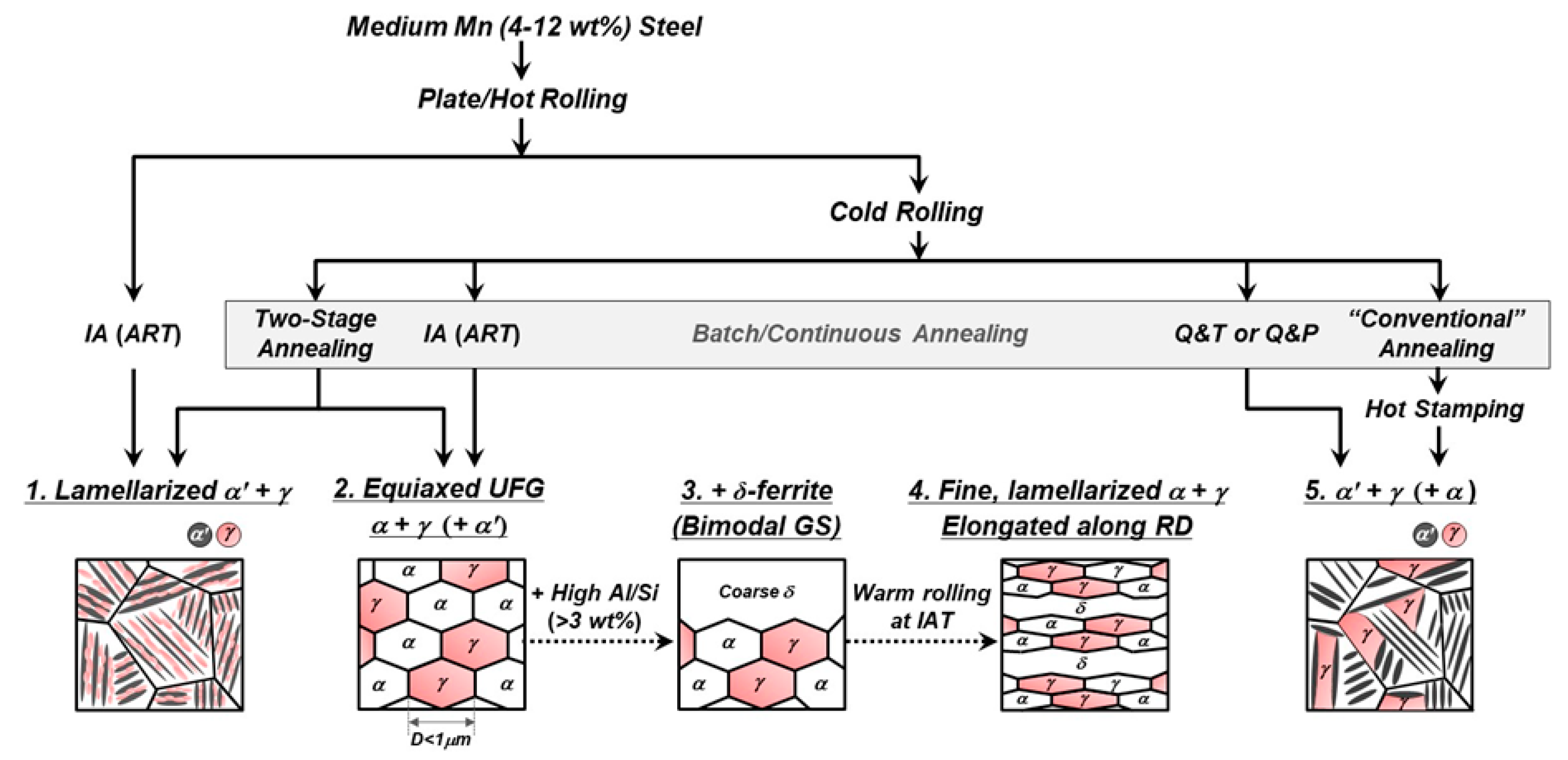
2. Thermomechanical Processing and Metallurgy of Medium–Mn Steels

The range of “medium Mn” is defined typically between 4 and 12 wt pct, i.e., lower compared to that of high Mn (≥15 wt pct) twinning-induced plasticity (TWIP) steels. Notably, “intercritically annealed” medium-Mn steels are capable of achieving a superior combination of strength, ductility, and work-hardening capability. Their high work-hardening rate is associated with the TRIP effect or a combination of two plasticity-enhancing mechanisms, the TWIP and TRIP effects. Despite the lower Mn contents compared to high Mn steels, medium-Mn steels achieve excellent mechanical properties, with a product of ultimate tensile strength and total engineering strain in the range of 5000 to 90,000 MPa∙pct [2,3]. These steels have substantially higher yield strengths than their austenitic counterparts. Austenite stability can be modified by partitioning Mn during intercritical processing and strength can be enhanced by incorporating martensite into the microstructure, using a variety of processing approaches.
The production routes for medium-Mn steels and resulting microstructures are shown in the schematic of Figure 1. Note that many of the microstructural variants presented in Figure 1 are developed through processing of a “cold-rolled” product. It is anticipated, however, that some of the processing and microstructural engineering concepts developed for the cold-rolled product can be extended to hot-rolled or plate-rolled products.
Mn alloying enhances hardenability, i.e., it delays ferritic/bainitic transformation during hot/plate rolling. Therefore, hot-rolled medium-Mn steels often have martensite matrix microstructures, which is one key difference from the ferrite matrix in as-rolled microstructures of conventional low alloyed steels. The evolution of the martensite matrix microstructure of medium-Mn steel is an important attribute to control during subsequent thermo-mechanical processing. For example, intercritical annealing (IA), i.e., annealing at a temperature between the Ac1 and Ac3 temperatures, of the martensitic starting microstructure of a medium-Mn steel results in the partial reversion of martensite to austenite. For specimens that are not cold-worked prior to annealing, the preferred sites for austenite formation are martensitic lath interfaces and prior austenite grain boundaries. Consequently, the austenite reversion heat–treatment (ART) or IA of undeformed martensitic starting microstructures produces a “lamellarized” duplex microstructure consisting of α′-martensite and austenite [1] (first example in Figure 1). The “α′-martensite” after reversion heat-treatment may not preserve its martensitic nature because recovery and/or partial recrystallization take place in the martensitic regions during IA [8]. On the other hand, IA of a deformed or cold-worked starting microstructure leads to a uniform distribution of “equiaxed” ferrite and austenite, usually characterized by an ultra-fine-grained (UFG) microstructure, resulting from the simultaneous recrystallization of ferrite and growth of austenite [1] (second example in Figure 1). The two (lamellarized and equiaxed) microstructures are the most common forms amongst the different microstructural variants of medium-Mn steel grades. Note that the lamellarized microstructure does not have to be produced from a hot-/plate-rolled condition, e.g., it can be generated by two-stage annealing (consisting of austenitization annealing, quenching, and austenite reversion heat-treatment) of a cold worked microstructure. It should also be noted that two-stage annealing of a cold-rolled steel can develop either a lamellarized or equiaxed microstructure, depending on the initial Mn distribution and thermal cycle [9,10]. One variant of the equiaxed microstructure is generated by a “double soaking” heat treatment, consisting of an IA stage to stabilize austenite through Mn partitioning, followed by a very short secondary soaking stage [11,12]. The second soak is performed at a relatively high temperature in order to partially or fully replace intercritical ferrite with austenite that is converted to athermal martensite during quenching, and to create a higher-strength TRIP microstructure containing both martensite and austenite [11,12]. This microstructure offers attractive strength/ductility combinations, but it is likely less attractive in applications requiring substantial resistance to HE, without an additional tempering step.
A key attribute of both lamellarized and equiaxed microstructures is the presence of either UFG or nanolaminate [13] retained austenite, respectively, which contributes to enhanced work hardening and high ductility associated with the TRIP and/or TWIP effect. For medium-Mn steels, submicron-sized retained austenite grains, typically smaller than 500 nm, are obtained by a relatively simple IA step or austenite reversion annealing. It is also important to note that IA is essential to obtain a substantial amount of retained austenite with adequate stability as carbon (C) and Mn, both strong austenite stabilizers, partition from ferrite or martensite to austenite during IA. The origin of the development of a high fraction of UFG austenite in the intercritically annealed medium-Mn steel is largely associated with the Mn austenite-stabilizing effect [2,14,15]. When the bulk Mn content is increased, the reverse transformation to austenite starts at a lower temperature and, thus, a relatively high fraction of austenite may be produced before recrystallization takes place. Suh and Kim [2] pointed out that grain growth in the ultra-fine regions is restricted even at a relatively high IA temperature (~800 °C), presumably due to the nature of the two-phase microstructure.
Some alloy and microstructure variants of typical UFG duplex medium-Mn steel are also shown in Figure 1. For example, many investigators considered aluminum (Al) and silicon (Si) as essential alloying elements for medium-Mn steels. These elements are useful in raising the intercritical temperature and, thus, increasing the solute partitioning kinetics. In addition, it has been recognized that a bimodal grain structure can be achieved in medium-Mn steels by the addition of Al and Si, when the amount of both alloying elements exceeds 3 wt pct [16,17]. Fe–xC-6 wt pct Mn steels were employed in the initial studies of Al-added medium-Mn TRIP steels [16,18]. Figure 2 shows the influence of Al and Si additions on the pseudo-binary phase diagram for an Fe–6.0Mn–xC alloy system (all in wt pct), calculated by using Thermo-Calc® software. The Al and Si additions expand both the α-ferrite and δ–ferrite stability regions, resulting in the formation of layers of coarse δ–ferrite grains in the hot–/cold-rolled microstructures (third example in Figure 1). For specific alloy and heat-treatment conditions, a steel specimen with a UFG microstructure often experiences pronounced localized deformation and plastic instability, associated with dynamic strain aging [19]. The introduction of coarse δ–ferrite grains in the UFG structure, resulting in a bimodal grain size distribution, may eliminate the localized deformation and plastic instability and enhance ductility [20]. In another alloying and processing variation, “warm” rolling at an IA temperature has been applied to Al-free and Al-containing medium-Mn steels, leading to an even finer-grained, lamellarized microstructure, elongated along the rolling direction [21,22,23] (fourth example in Figure 1).
Some investigations applied “conventional” quenching and tempering (Q&T) to medium-Mn steels in order to produce a tempered martensite matrix microstructure containing an adequate/high fraction of retained austenite, resulting from the effect of the Mn addition on lowering the martensite start (Ms) and martensite finish (Mf) temperatures [24,25] (fifth example in Figure 1). Quenching and partitioning (Q&P) heat treatments can be used to increase and control the fraction of retained austenite [24,26,27]. These Q&T and Q&P microstructures consist of metastable retained austenite within the martensitic matrix, somewhat similar to the lamellarized microstructure achieved by austenite-reversion heat-treatment (first example in Figure 1). However, tempering/partitioning treatments involve carbon redistribution at low temperatures, whereas austenite reversion typically requires a longer hold time at a sufficiently high “IA” temperature to partition Mn. Thus, the degrees of tempering and solute partitioning are lower in the Q&T and Q&P processes, which may lead to lower ductility, but ultrahigh strength and a higher “yield ratio” (the ratio of yield strength to ultimate tensile strength) compared to the austenite reversion treated steel. In addition, retained austenite in quenched and tempered (or partitioned) specimens can have both bulky and film-type morphologies and is metastable, resulting in a pronounced TRIP effect. In contrast, austenite reversion is expected to induce partitioning of substitutional alloying elements (e.g., Mn, Si, and Al) in addition to C, which can lead to both TRIP and TWIP effects. The use of medium-Mn steels in Q&P processing may offer several advantages in addition to the Mn austenite stabilizing effect. For Mn-alloyed steels, alloying and processing strategies can be developed to decrease the Mf temperature slightly below room temperature; in this condition, one can apply “room temperature” quenching and partitioning, which is potentially easier to implement industrially compared to “conventional” Q&P processing [28,29,30,31].
Similar to the Q&T/Q&P applications, the application of hot or “warm” stamping to medium-Mn steels produces microstructures with retained austenite in addition to martensite, which provides an ultrahigh strength (tensile strength up to 1.6 GPa) and a ductility (total elongation up to 44 pct) much higher than that of conventional 22MnB5 press-hardened steel (7–8 pct) [32,33,34]. There are additional advantages of the application of medium-Mn steel to hot stamping over the conventional low-alloy boron-added steels; for example, Mn-associated enhanced hardenability reduces the cooling rate requirement and enables alternative cooling approaches [32,34]. In addition, compared to low-alloy steels, lower reheating (austenitizing or IA) temperatures can be employed for hot stamping of medium-Mn steel, which reduces both the heating time and potentially production costs, and also influences the behavior of metallic coatings that may be employed.

3. Alloying and Microstructural Effects on HE Characteristics

The microstructural engineering of medium-Mn steels, introduced in Section 2, is generally focused on optimizing the strength–ductility balance for implementation in the automotive industry. To design materials with resistance to HE, it is also of importance to identify the relationship between microstructure and HE in medium-Mn steels. Review of the mechanical behavior of medium-Mn steels in air (H-free conditions) has been reported rather comprehensively by others [2,3,4]. Therefore, the review in the following sections focuses on the H uptake and embrittlement characteristics of different medium-Mn steel microstructures, mostly evaluated by means of electrochemical H charging and slow strain rate testing (SSRT). The SSRT performed in previous studies usually involved tensile testing of sheet-type specimens at a slow strain rate typically in the range of 10−4·s−1 to 10−7·s−1.
More specifically, the effects of constituent morphologies, austenite fraction and stability, alloying elements, e.g., Al, Si, and copper (Cu), and processing routes on the HE sensitivity are presented here.

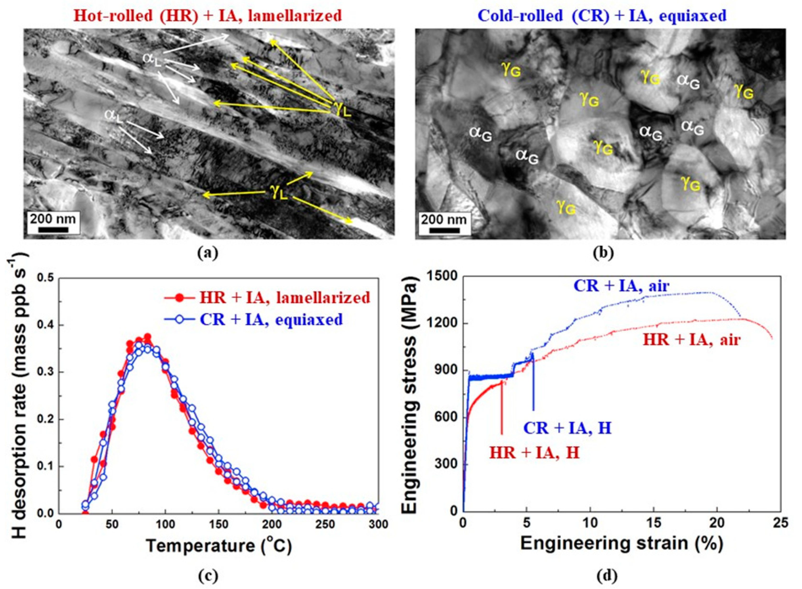
3.1. Equiaxed Versus Lamellarized Morphology

A number of investigations employed SSRT to compare the HE characteristics of two different (lamellarized and equiaxed) morphologies of a medium-Mn steel microstructure, as summarized in Table 1. In SSRT, relative elongation loss due to H (HE index) is commonly used as a metric to measure a HE sensitivity of a material, and the HE index is given by the following equation:
HE index (%) = (TEH-free −TEH-charged)/TEH-free × 100%
where TEH-free and TEH-charged are the total elongations obtained from SSRT of tensile specimens in H-free and H-charged conditions, respectively. Interestingly, three separate investigations had similar interpretations with respect to the relative H-resistance of the two morphologies [35,36,37]. Cameron et al. [35] applied two different processing routes to a medium-Mn steel (Fe–0.01C–9Mn–3Ni–1.4Al, in wt pct) to generate different microstructures. That is, IA of (i) as-quenched and (ii) cold-rolled martensitic microstructures led to lamellarized martensite–austenite and equiaxed ferrite–austenite microstructures, respectively. The SSRT results indicated that both microstructures showed similar degrees of elongation loss (91–92 pct) after H charging, despite the observations that the equiaxed morphology absorbed a much higher H concentration for a given H-charging condition (15.6 wppm in equiaxed vs. 1.87 wppm in lamellarized) and had a higher ultimate tensile strength (1100 vs. 900 MPa). In this regard, Cameron et al. [35] interpreted that the equiaxed microstructure was more resistant to HE, compared to the lamellarized condition.
Han et al. [36] conducted a systematic comparison of the two morphologies, comparing specimens having similar austenite volume fractions and similar H concentrations prior to the tensile tests. Figure 3a,b shows transmission electron microscopy (TEM) micrographs of the lamellarized martensite austenite and equiaxed ferrite austenite microstructures, produced through IA of hot-rolled and cold-rolled specimens, respectively. Figure 3c indicates similar H concentrations of the electrochemically H-charged specimens from the H thermal desorption analysis (TDA) results for the two morphologies. The SSRT results of the H-charged specimens, Figure 3d, indicate that the equiaxed microstructure better resisted HE, which is consistent with the interpretation of Cameron et al. [35]; it should be noted that, again, the equiaxed condition had a higher strength. Shen et al. [37] compared a slightly different combination of microstructures, i.e., a mixture of lamellarized and equiaxed structures having coarse lamellae (10–20 μm in length) and grains (~1.5 μm) versus a mainly fine lamellarized microstructure (lamellae 1–5 μm in length). The study by Shen et al. [37] is also consistent with the studies by Cameron et al. [35] and Han et al. [36], in that the microstructure containing equiaxed grains exhibited a higher resistance to HE. It should be pointed out, however, that the difference in microstructural feature sizes is also considered a critical factor that affects the HE characteristics in addition to the morphological change in the study by Shen et al. [37]. Specifically, Shen et al. [37] reported that as compared to the “larger” mixed microstructure, the “finer” lamellarized microstructure had a larger density of H-trapping interfaces, which accelerated H uptake and, thus, promoted embrittlement particularly at a prolonged H-charging time (24 h). It is also important to note that this hypothesis alone does not clearly explain the microstructure-dependent HE susceptibility for shorter H-charging time conditions (2 and 8 h), which resulted in relatively comparable H concentrations between the different microstructures.
Jeong et al. [10] designed experiments to decouple a variety of secondary factors; in their study, lamellarized and equiaxed conditions had similar strength levels, austenite fractions, and austenite mechanical stabilities (with respect to mechanically-induced martensitic transformation). In addition, Jeong et al. [10] explored a relatively wide range of H concentrations (0.4 to 4.4 ppm). Figure 4a–d summarizes the influence of H concentration on SSRT results for the lamellarized and equiaxed microstructures, produced through different two-stage annealing cycles. Interestingly, these results [10] were clearly different from the three other above-referenced studies [35,36,37] in that the lamellarized condition was less H-sensitive for a similar H content; note in Figure 4c that the H-induced elongation loss is much lower for the lamellarized condition. Particularly for low H concentrations (0.4–1.6 ppm), the H-induced ductility loss of the lamellar structure was negligible (Figure 4c).
It is unclear why these results are not consistent with the other studies presented in Table 1, but it might suggest that there can be other factors that affect the severity of HE. For instance, Jeong et al. [10] concentrated on the influence of connectivity (or microstructural percolation) of the austenite on H transport to explain the greater H-resistance of the lamellarized microstructure (Figure 4a–c). Jeong et al. performed electrochemical H permeability measurements and showed that H diffusion was slower in the lamellarized microstructure compared to the equiaxed microstructure. They explained that an austenite grain in the lamellarized microstructure is more likely to be connected to neighboring austenite grains, which effectively obstructs H migration. They suggested that the inhibited percolation through austenite decelerates H accumulation near the crack tip and, thus, positively contributes to H-resistance. The ability of H to percolate through mixed ferrite–austenite microstructures has also been proposed by Fielding et al. [38] as a critical factor in HE-resistance.
On the other hand, Han et al. [36] focused on the fact that the fracture and cracking mechanisms are different in the two conditions. For the lamellarized microstructure, H-induced fracture occurred preferentially along “prior” austenite grain boundaries, whereas fracture in the equiaxed microstructure occurred either across the ferrite grains or along the granular retained austenite grain boundaries. Greater degrees of crack deflection were present in the equiaxed condition, which was interpreted to improve H-resistance, as compared to the lamellarized condition. A more recent study [39] performed three-dimensional (3D) atom probe tomography (APT) of the lamellarized condition, used by Han et al. [36]. The 3D-APT analyses revealed noticeable segregation of C, Mn, and P at prior austenite grain boundaries, which may explain the lamellarized microstructure being more prone to prior austenite grain boundary cracking. The unfavorable influence of the combination of H and segregated elements (e.g., Mn, Si, P, and S) on the severity of HE has been demonstrated in other publications [40,41]. Therefore, control of impurity levels and segregation can also be a factor determining which microstructures better resist HE.
According to the results summarized in Table 1, the effect of microstructural morphology on H absorption is usually not significant for microstructures with a similar amount of austenite (e.g., the studies by Han et al. [36] and Jeong et al. [10]). In contrast, only the study by Cameron et al. [35] was unique, given that the equiaxed morphology absorbed a higher H content, nearly an order of magnitude than that of the lamellarized microstructure, for the same charging condition. The larger H absorption may partly be explained by the higher fraction of austenite, where H is more soluble than in martensite (and ferrite), in the equiaxed microstructure.

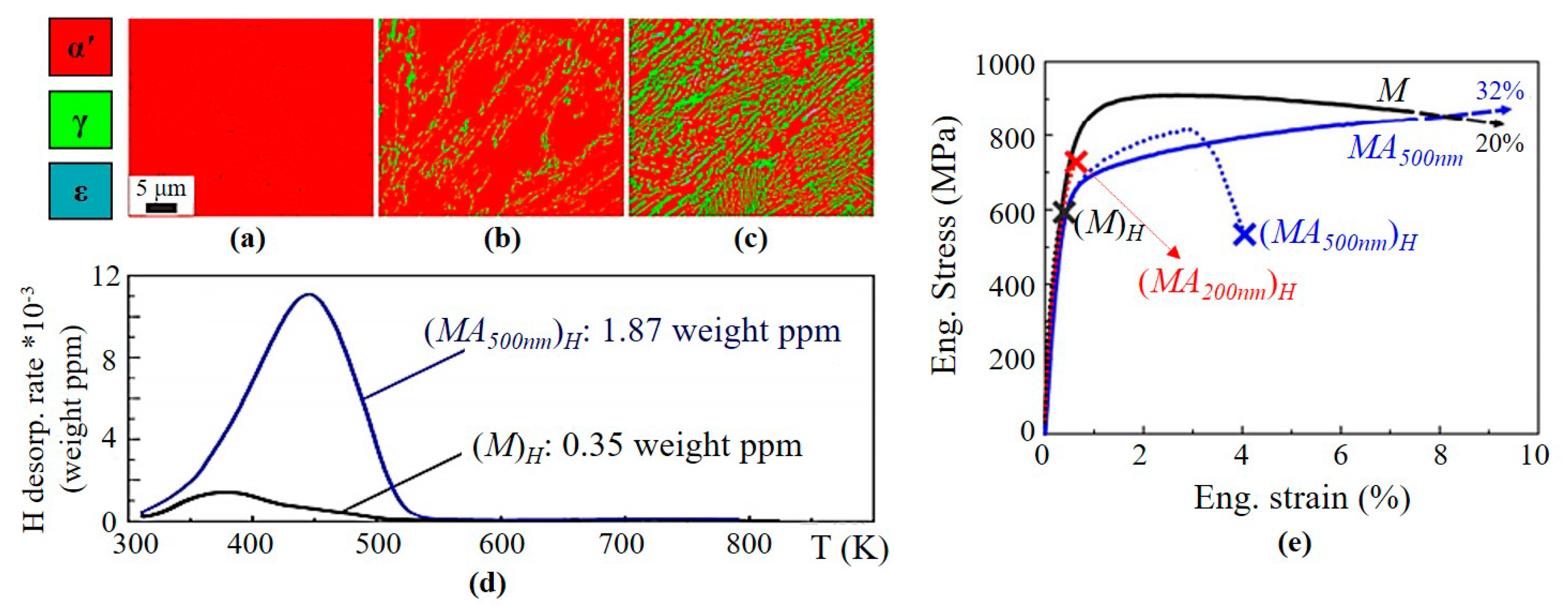
3.2. Retained Austenite and Mechanically–Induced Martensitic Transformation

Retained austenite is the key constituent controlling activation of the TRIP and/or TWIP effect, which have a pronounced influence on the strain hardening behavior, in medium-Mn steels. Some studies suggest that retained austenite is also beneficial for the resistance of medium-Mn steel to HE because of its high H-trapping capability or its positive contribution to overall ductility (toughness). As an example, Wang et al. [42] investigated the influence of austenite fraction and film thickness, associated with austenite grain size, on H absorption and HE characteristics of a medium-Mn steel (Fe–0.01C–9Mn–3Ni–1.4Al, in wt pct), as shown in Figure 5. Figure 5a shows an electron backscatter diffraction (EBSD) phase map of a fully lath martensitic microstructure in the as-quenched condition. Wang et al. [42] produced two additional microstructures by applying an austenite reversion treatment to the as-quenched martensite. When the steel specimen was austenite reversion-treated at 600 °C with a hold time of 1 h, the microstructure contained austenite with a volume fraction of 10 pct and an average thickness of 200 nm, as shown in the EBSD phase map in Figure 5b. As the hold time at 600 °C increased to 8 h, the austenite fraction increased to 35 vol pct and the average thickness of the austenite films increased to 500 nm (Figure 5c). The H-TDA results by Wang et al. [42] (Figure 5d) indicate that the specimen containing a greater amount of retained austenite absorbs more H for a given H-charging condition because H solubility in austenite is much higher than in ferrite or martensite. The engineering stress–strain curves obtained by SSRT (Figure 5e) show that the H-induced ductility loss became less significant with increasing austenite fraction. Similar to the study by Wang et al. [42], Du et al. [43] produced three different microstructures from a medium-Mn steel (Fe–0.065C–5.45Mn–0.2Si, in wt pct): an as-quenched martensitic microstructure and two intercritically annealed microstructures containing different amounts of retained austenite within the martensitic matrix. Du et al. [43] also presented a beneficial effect of retained austenite with respect to the H-resistance in the medium-Mn steel. Figure 6 shows the SSRT results obtained by Du et al. [43], indicating that with increasing fraction of retained austenite, the H content of the specimen significantly increased, and the H-induced elongation loss became less significant.
There have been detrimental effects of deformation-induced transformation of retained austenite to martensite on HE reported. A study of Shao et al. [44] falls into this category, for example. Figure 7 shows retained austenite volume fraction for a medium-Mn steel (Fe–0.2C–5Mn–0.6Si–3Al, in wt pct) as a function of engineering tensile strain [44]. The data points at zero pct strain in Figure 7 indicate that there is little difference in the initial retained austenite volume fraction for the various IA hold times employed at 750 °C. However, the H-induced elongation losses in SSRT (HE index), presented in Figure 7b, became larger as the hold time increased. Shao et al. [44] explained that for the longer hold time conditions, the average austenite grain size was much larger, leading to a decrease of the mechanical stability during testing (Figure 7a). Shao et al. [44] also showed that austenite grain coarsening due to the longer hold time resulted in the absorption of slightly less H. The reduced uptake of hydrogen was attributed to a decreased area fraction of H-trapping sites associated with phase interfaces in the coarser microstructure.
Zhang et al. [45] investigated the influence of the IA temperature (700–850 °C) on HE of a medium-Mn steel (Fe–0.20C–0.6Si–4.9Mn–3.1Al, in wt pct); in their study, the HE susceptibility increased with increasing IA temperature, which was attributed to decreased austenite stability.
A detrimental effect of mechanically-induced martensite is also highlighted in a study by Wang et al. [46], who investigated the influence of pre-strain on HE of a medium-Mn steel (Fe–0.25C–8.7Mn–2.69Al–0.5Si, in wt pct). Wang et al. [46] reported that pre-straining resulted in an increase in dislocation density and partial transformation of austenite to martensite, leading to a substantial increase in the HE susceptibility. Liu et al. [47] also explored the pre-strain effect on H-induced cracking of medium-Mn steel, emphasizing the importance of austenite mechanical stability to suppress H-induced damage, similar to the study by Wang et al. [46].
It should be noted that, when the annealing conditions are varied, the steel strength, which is also a factor influencing the H-sensitivity, changes, in addition to the microstructure. For example, the studies by Wang et al. [43] and Du et al. [43] clearly showed that the HE susceptibility decreased with increasing retained austenite fraction (Figure 5 and Figure 6). However, in these studies, the specimen with a higher fraction of retained austenite exhibited a reduced yield strength, which may have contributed to the increased H-resistance. In contrast, the study by Shao et al. [44] clearly showed that, as IA time increased, HE became increasingly severe (Figure 7), despite the decreases in yield and tensile strength. Therefore, it was clear, in this study, that the H-resistance of medium-Mn steels was influenced by the mechanical stability of retained austenite.

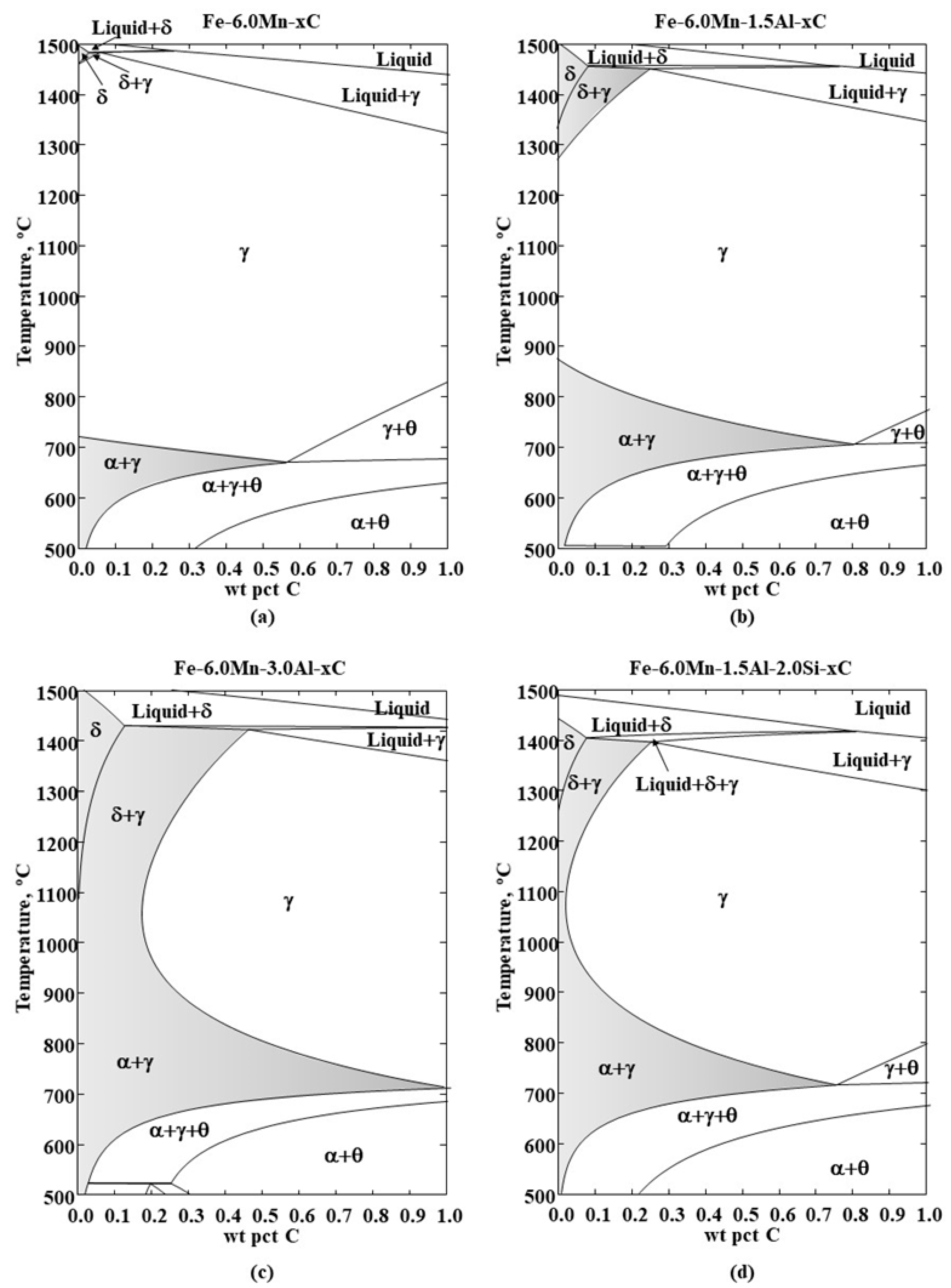
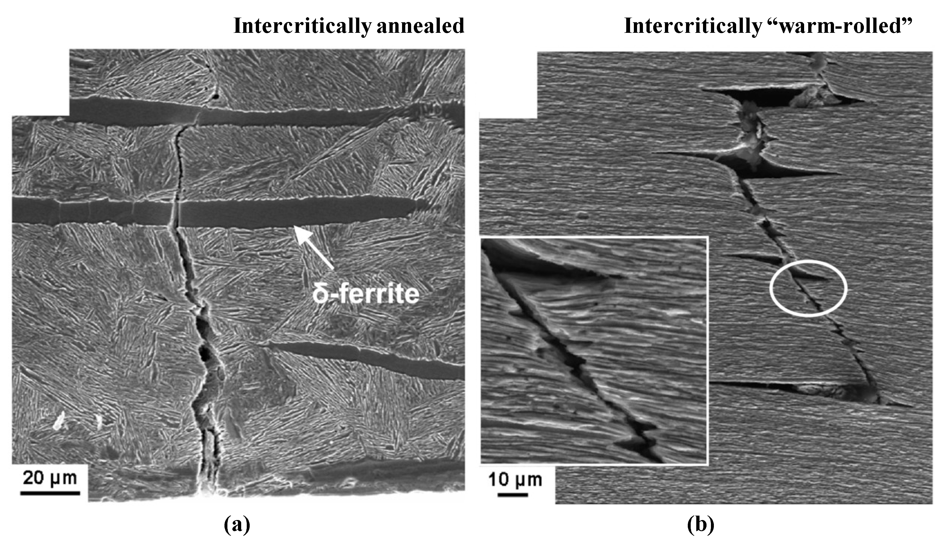
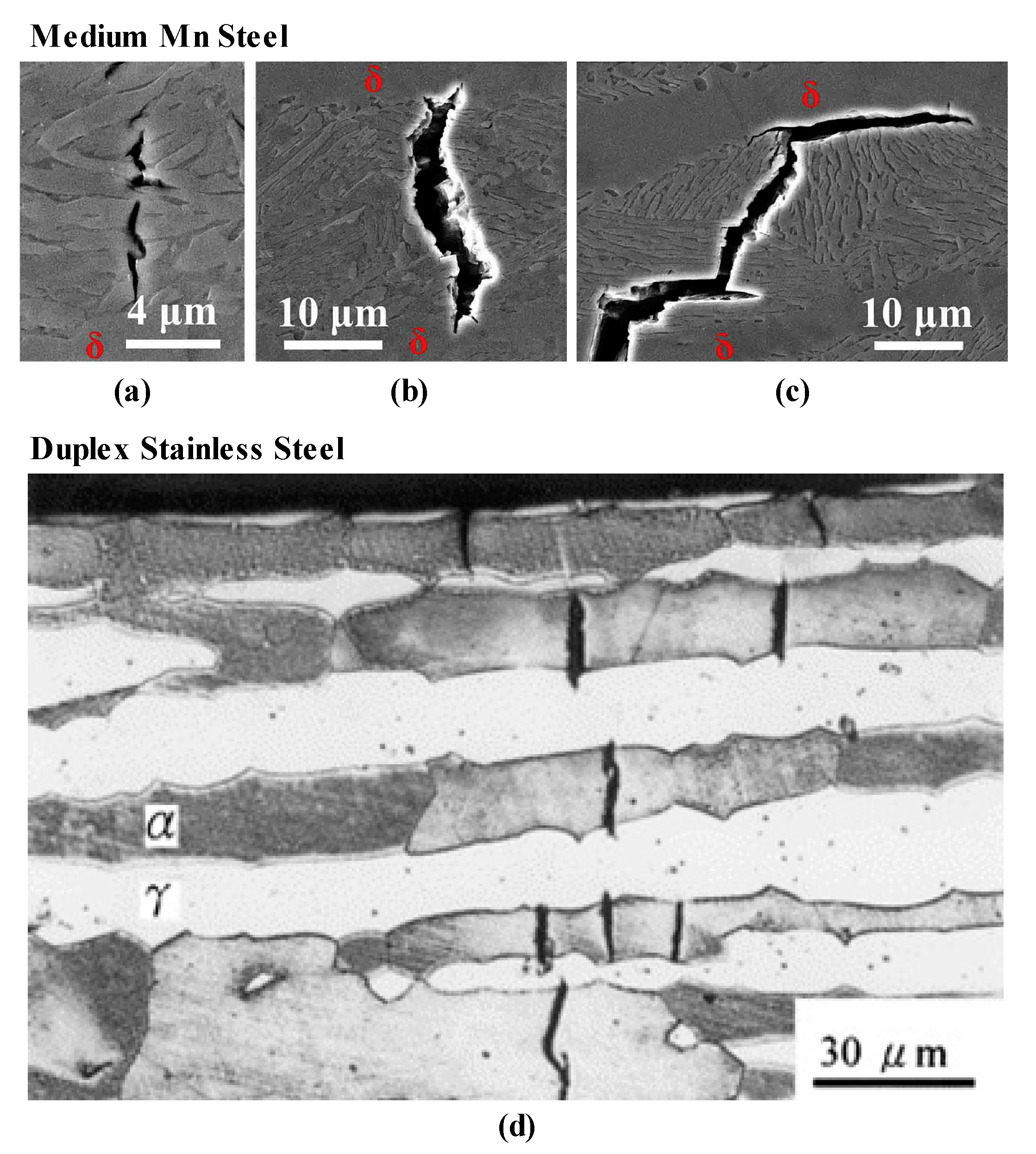
3.3. Al- and Si-Alloyed Medium-Mn Steels Containing Coarse δ-Ferrite Grains

A few investigations evaluated the HE characteristics of substantially Al- and Si-alloyed medium-Mn steels containing coarse δ-ferrite grains (Table 2). Figure 8a,b shows the microstructures of medium–Mn steels containing lower (1.1 wt pct) and higher Al contents (3.1 wt pct), respectively [48]. The microstructure of the low Al medium-Mn steel exhibited a relatively uniform distribution of UFG austenite and ferrite (Figure 8a), while the high-Al/medium-Mn steel contained coarse δ-ferrite layers in addition to the UFG austenite–ferrite regions (Figure 8b). Figure 8c,d shows the tensile properties of the low-Al and high-Al steels in H-free (air) and H-charged conditions, evaluated by means of SSRT. In the H-free condition, the low Al steel exhibited a high ultimate tensile strength and high work-hardening rate, associated with a pronounced TRIP effect (Figure 8c). Comparatively, the high-Al steel had an increased ductility and a low work-hardening capacity (Figure 8d). Ryu et al. [48] measured austenite fraction of each specimen as a function of the tensile strain and confirmed that the mechanical stability of austenite in the high-Al steel was higher compared to the low-Al steel. The SSRT results of H-charged specimens (Figure 8c, d) indicate that the H-induced loss in ductility was more pronounced in the low–Al/medium-Mn steel containing less stable austenite.
Considering the different H-sensitivity between the alloys, Ryu et al. [48] suggested that the detrimental effect of strain-induced martensite is because the transformation leaves the inherited H in a more mobile state. We interpret that the increase in strength due to the austenite to martensite transformation also increases vulnerability to HE. Interestingly, two other studies (by Wang et al. [49] and Shao et al. [44]) on the HE of high Al– and Si–alloyed medium-Mn steels reported observations similar to those of Ryu et al. [48]. That is, retaining a sufficient amount of austenite may benefit the HE resistance of medium–Mn steels, but suppression of the mechanically–induced martensitic transformation is often more critical; a similar finding was described in Section 3.2. The studies by Wang et al. and Shao et al. are also summarized in Table 2.
The beneficial effect of coarse δ–ferrite grains or a bimodal grain size distribution on the mechanical behavior in the H–free condition is well known [17,51]. That is, it has been suggested that there is enhanced strain partitioning in coarse, soft δ-ferrite grains, and thus, γ in the UFG region is stabilized, until larger strains are reached during deformation. This strain-partitioning behavior is believed to positively affect overall ductility and toughness. However, the direct role of δ–ferrite with respect to H-resistance is not clear in the studies summarized in Table 2. More often than not, the overall HE characteristics of a medium-Mn steel appear to be affected more significantly by the austenite fraction and mechanical stability rather than by the presence of δ–ferrite. However, there is some evidence that δ–ferrite layers might play a role in cracking or influence the fracture path in H testing. Wang et al. [49] reported that H-induced cracks are often arrested by the δ–ferrite layer. Warm rolling at an IA temperature is reported to provide a refined microstructure and significantly improved the H–resistance of a medium–Mn steel containing δ–ferrite. Zhang et al. [50] considered the refined δ–ferrite layers in a warm-rolled specimen to be beneficial, hypothesizing that the soft δ–ferrite exhibits low HE susceptibility, resulting in an effective crack termination mechanism. The contribution of the refined δ–ferrite layers in a warm-rolled specimen to deflection of the H–induced cracks is highlighted in Figure 9 [50]. Scanning electron microscopy (SEM) fractographs compare the path and morphology of the H-induced cracks in medium-Mn steels after conventional IA and after intercritical warm rolling. The crack in the intercritically annealed steel was slightly deflected at the δ-ferrite regions (Figure 9a). In the warm-rolled microstructure, the fine lamellar structure with δ–ferrite layers resulted in delamination-type fracture; the crack that encountered the δ–ferrite layer was significantly deflected and propagated in the rolling direction, rather than in the transverse direction (Figure 9b).
Wang et al. [49] suggested a different, but interesting view on the role of the δ–ferrite, i.e., when a large fraction of δ–ferrite exists in a medium-Mn steel microstructure, C and Mn are expected to be enriched in the non-δ-ferritic (mostly martensitic) regions in the as-hot rolled condition, i.e., before an austenite reversion treatment. Therefore, it can be assumed that, in a δ–ferrite-containing microstructure, higher amounts of austenite-stabilizing alloying elements, such as C and Mn, are partitioned to austenite during intercritical treatment, further enhancing the stabilization of austenite.
In addition to its role in δ–ferrite stabilization, Al additions significantly increase SFE, which is associated with mechanical stability of austenite. This dual role of Al may be important in the future design of a H-resistant ferrite–austenite microstructure with increased mechanical stability of austenite. There has been considerable discussion of the interaction between Al and H in “high” Mn TWIP steel [52,53,54]. In summary, Al has been found to slow the diffusion of H in a high-Mn TWIP steel, which leads to the suppression of H uptake and embrittlement [53]. It was also suggested that an Al2O3 oxide layer that forms at the surface of TWIP steel interferes with H absorption and, thus, prevents the H uptake [54].

3.4. Other Alloying Elements and Precipitates

Carbide and nitride precipitates containing molybdenum (Mo), vanadium (V), niobium (Nb), and titanium (Ti) have long been known to be effective in mitigating H-induced fracture of steels. However, the influence of micro alloy precipitates has not been broadly explored in medium-Mn steels. Park et al. [55] evaluated the HE resistance of medium-Mn steels micro alloyed with Nb, Ti, and V compared to a reference steel (Fe–6Mn–0.08C, in wt pct). They reported that the effects of the microalloying additions on the H-resistance were insignificant for the investigated test conditions. They explained that the insignificant effects of the precipitates were due to the two-phase nature of the microstructure, i.e., micro alloy carbides formed primarily in the ferritic regions, but the H atoms are expected to be trapped preferentially in the austenite, where H is more soluble than in ferrite. It is an important observation that, in a duplex microstructure, carbides and nitrides are mostly present in the ferrite, rather than the austenite, and may not actively interact with H atoms in the microstructure.
Cu is not a carbide/nitride former but can also precipitate in steel, contributing to precipitation strengthening. Li et al. [56] investigated precipitation behavior and HE in Cu–free (Fe–7Mn–2.5Ni–1.5Al–0.01C, in wt pct) and Cu-added medium-Mn steels (Fe–0.01C–7Mn-–2.5Ni–1.5Al–1.5Cu, in wt pct). In processing these two steels, Li et al. [56] used two-stage annealing; the first IA was performed at 630 °C for 1 h and the second step involved “tempering” at 500 °C. The hold times in the “tempering” step used for the Cu–free and Cu-added steels were 5 and 2 h, respectively. Figure 10a,b shows the 3D–APT results for the ferritic and austenitic regions in the Cu-added medium-Mn steel, indicating that Cu, as opposed to the microalloying example above [55], precipitated primarily in the austenite, rather than in the ferrite, despite the increased solubility of Cu in austenite compared to ferrite. In contrast, the APT map of the ferritic region (Figure 10a) shows non-uniformity in the Ni signal; TEM selected area diffraction analysis by Li et al. [56] revealed that the Ni-enriched regions in the ferrite are associated with B2 NiAl precipitates. Figure 10c shows the influence of Cu on the HE characteristics, evaluated by SSRT. The Cu-added steel exhibited a smaller elongation loss due to H, indicating a higher resistance to HE compared to the Cu-free steel. It should be noted that the interpretation of the primary role of the Cu precipitates with respect to the material’s H-resistance is different from the “conventional” mechanism from a viewpoint of precipitates being strong H-traps. The authors explained that the improved H–resistance in the Cu-added steel was due to increased strain compatibility between austenite and ferrite, resulting from the Cu precipitation. Li et al. [56] employed nano-indentation to support this view. Figure 10d shows the average indentation hardness of the ferrite and austenite phases in the Cu–free and Cu–added steels. In both the Cu-free and Cu-added steels, the ferrite was relatively hard (average nano-hardness > 8 GPa), possibly due to the NiAl associated precipitation strengthening of ferrite. In the Cu-free steel, the average hardness of ferrite (~10 GPa) is much harder than that of austenite (~5 GPa). In the Cu–added steel, however, Cu precipitation strengthening led to a significant increase in the average hardness of the austenite, which reduces the difference in hardness between the two constituent phases and, thus, improves the strain compatibility. The possible detrimental effect of strain incompatibility between neighboring constituent phases on the H–induced cracking of a medium–Mn steel was also discussed in a recent publication by Sun et al. [57]. It should be noted that, in the study by Li et al. [56], the improved H–resistance was noted despite the fact that the mechanical stability of the austenite was lower in the Cu-added steel. This study is one of only a few examples indicating that HE was less significant in the presence of a more pronounced TRIP effect.
Yoo et al. [58] reported that additions of 1–3 wt pct Cu improved the H–resistance of a duplex (ferrite austenite) lightweight steel (Fe–0.8C–15Mn–7Al, in wt pct). In their study, the Cu additions promoted the formation of Cu–rich B2 phase primary along the austenite grain boundaries, which was interpreted to trap H atoms and slow H transport during deformation. Cu as a solute is also known to increase SFE of austenite; for example, in a study by Choi et al. [59], the addition of 1–2 wt pct Cu resulted in a transition from a TRIP to a TWIP deformation mechanism in a high Mn austenitic–based steel. Yoo et al. [58] also emphasized the role of Cu in increasing the SFE of austenite and promoting wavy glide of dislocations as low SFE and planar slip are generally thought to be detrimental to H-resistance in austenite. It should be pointed out that the alloy investigated in the study by Yoo et al. [58] was relatively highly alloyed, which resulted in a high SFE of the austenite that limited α′- or ε-martensitic transformation, in the steel microstructure designed to have a mixture of ferrite and austenite. Finally, Cu additions (1–2 wt pct) have been reported to enhance the HE resistance of a fully austenitic, high Mn TWIP steel (Fe–17Mn–0.8C, in wt pct) [60]. In this case, where Cu is not likely precipitated, it is more likely that the improvement in the H-resistance was associated with the increased SFE.

3.5. H–Induced Crack Initiation and Propagation

Table 3 summarizes several studies related to processing- and microstructure-dependent fracture surface appearance and crack initiation sites of H–embrittled, medium–Mn steels. In general, different phase boundaries and grain boundaries in medium-Mn steel microstructures may serve as crack initiation sites; microstructural morphologies and constituents strongly influenced the H–induced cracking and fracture of medium–Mn steels. A few studies [36,44] observed H–induced cracking at/near mechanically–induced martensite. The studies by Han et al. [36], Wang et al. [49], and Zhang et al. [50] indicated that the lamellarized austenite–martensite microstructure is often subject to H–induced cracking along the prior austenite grain boundaries. However, this type of fracture is not observed in an equiaxed ferrite–austenite microstructure which does not preserve its prior austenite grain structure. Instead, according to studies by Han et al. [36] and Shao et al. [44], the fracture surfaces of the equiaxed microstructure often display dimples filled with fine granular features. Examples of these features are indicated by yellow arrows in Figure 11a, the appearance of which is different from “typical” ductile micro voids indicated by white arrows in Figure 11a. A detailed image of a fine granular feature is shown in Figure 11b. Han et al. [36] and Shao et al. [44] interpreted the fine granular features to be associated with a region of either equiaxed austenite or mechanically–induced martensite. In particular, Han et al. [36] attributed the granular features to intergranular cracking along equiaxed austenite grain boundaries. Shao et al. [44] showed that the Mn content of the granular features was higher than that of surrounding microstructure implying they are associated with austenite (or mechanically–induced martensite) since austenite tends to be more enriched in Mn than ferrite or martensite in these steels.
When δ–ferrite is retained in a medium–Mn steel microstructure, H–induced cracks form preferentially in UFG regions rather than in the δ–ferrite layers [49,50]; examples are shown in Figure 12a–c. The interface between the δ-ferrite layer and UFG region is also a preferential cracking site (Figure 12c). Wang et al. [49] interpreted the δ-ferrite to be beneficial in terms of resisting H–induced cracks in a medium–Mn steel microstructure because the coarse δ–ferrite is the softest phase in the microstructure and softer phases are often less sensitive to HE. While the observations of Wang et al. [49] are important from a microstructural engineering perspective, they also highlight complexity in understanding and predicting the HE behavior of a multiphase steel. Figure 12 compares H–induced cracks that formed in a medium–Mn steel [49] and a 2205 duplex stainless steel [61]. In contrast to the medium–Mn multiphase steel (Figure 12a), cracks in the 2205 duplex stainless steel initiated in ferrite and arrested in austenite (Figure 12b); ferrite is softer than austenite in 2205 duplex stainless steels according to literature [62]. It is possible that “magnitude” of hardness of ferrite, relative to other phases, is a factor determining whether cracks are impeded in ferrite in these microstructures. Another factor contributing to the difference in cracking behavior may be the UFG microstructure in the medium–Mn steel. That is, the UFG microstructure contains an increased area fraction of grain boundaries and phase interfaces, which are potential H-trapping sites and crack initiation sites. It should also be noted that a bimodal grain size distribution is expected to increase strain incompatibility, and a few studies [56,57] have emphasized the possible detrimental effect of strain incompatibility in a microstructure with respect to the material’s H–resistance. This detrimental effect may be more significant in the medium–Mn steel microstructure containing UFG austenite and martensite, in addition to coarse ferrite grains, as compared to the duplex stainless-steel microstructure. Considering the complicated nature of crack initiation in multiphase, fine–grained microstructures, there are still remaining questions regarding the role of δ–ferrite in HE of medium–Mn steels.

4. Alloying and Microstructural Engineering Strategies to Improve H–Resistance

Drawn from the current review, key microstructure engineering mechanisms to mitigate the negative impact of H on Mn–alloyed duplex steels can be summarized as follows:
  • The microstructural morphology (equiaxed versus lamellarized) that has better HE resistance is inconclusively defined in the literature, as there are contradictory reports (Table 1). For the lamellarized microstructure, care must be taken to avoid solute segregation to prior austenite grain boundaries, as this microstructure may be prone to H-induced intergranular fracture along the prior austenite grain boundaries [36]. The equiaxed microstructure does not preserve its prior austenite grain structure. It is therefore postulated that the level of impurities in the steel may be more influential for the lamellarized morphology.
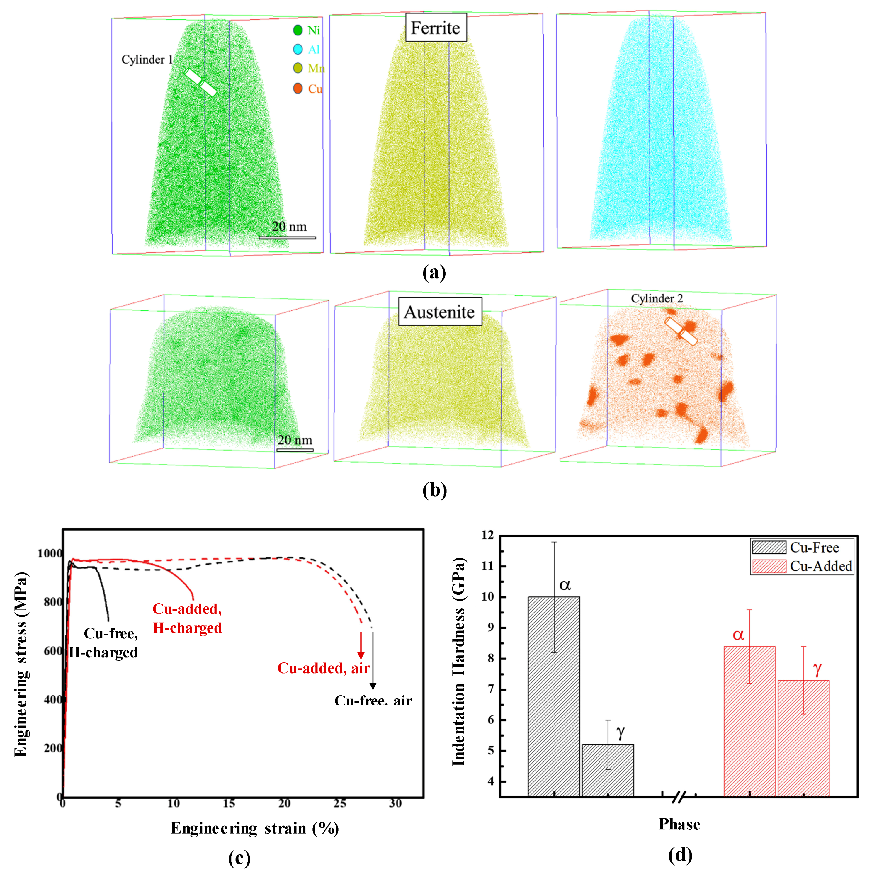
  • The effect of micro alloy precipitates is not clearly established for medium–Mn “duplex” steel, and future study is thus needed to evaluate their potential to mitigate HE. There are some reports on the beneficial effect of Cu–rich precipitates with respect to H-resistance.
  • It has been recognized, in a number of previous publications, that the H-resistance of medium–Mn duplex steel evaluated by SSRT testing is not necessarily dependent on the strength level; this statement is supported by the SSRT results in References [35,36,37,49,50].
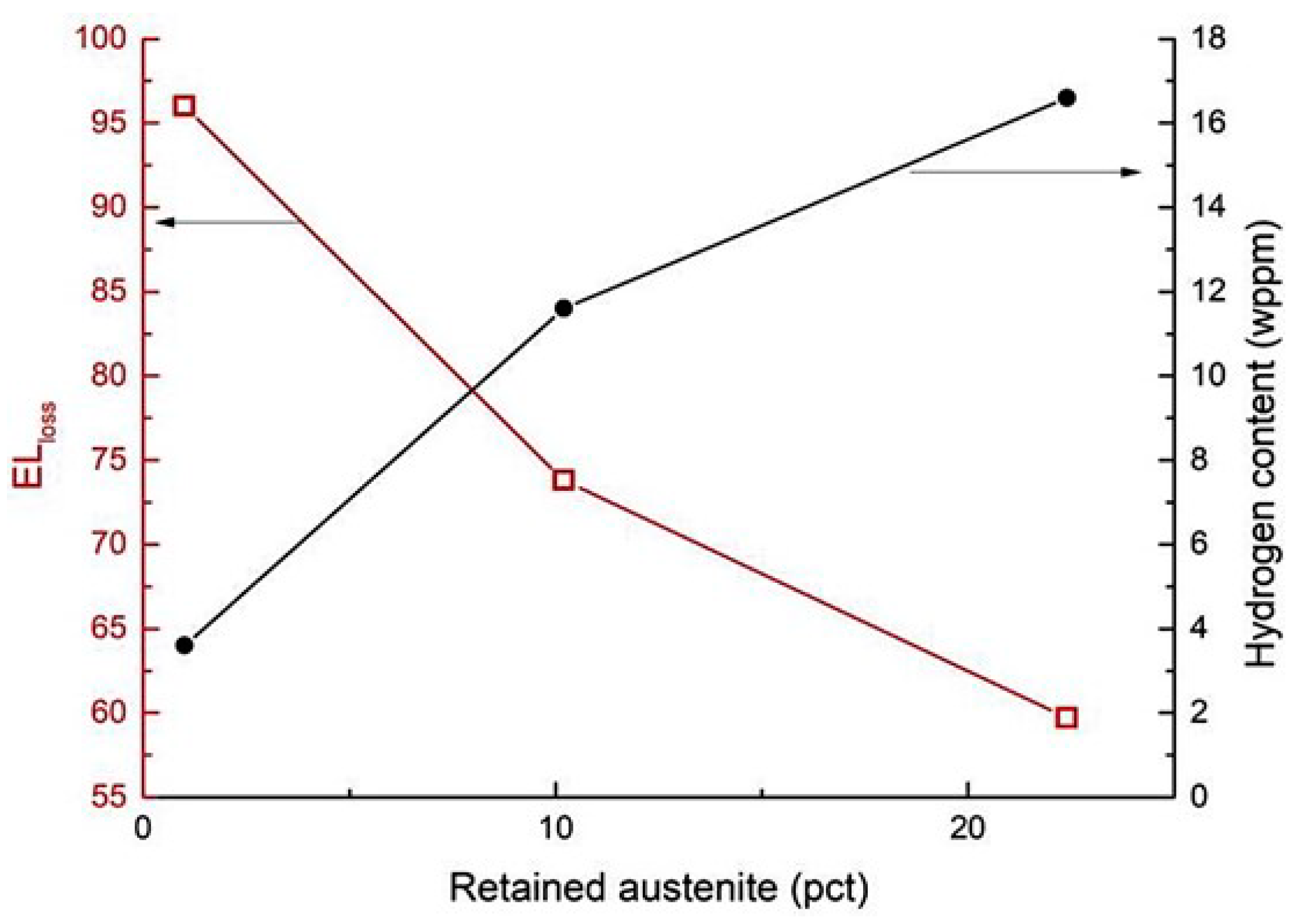
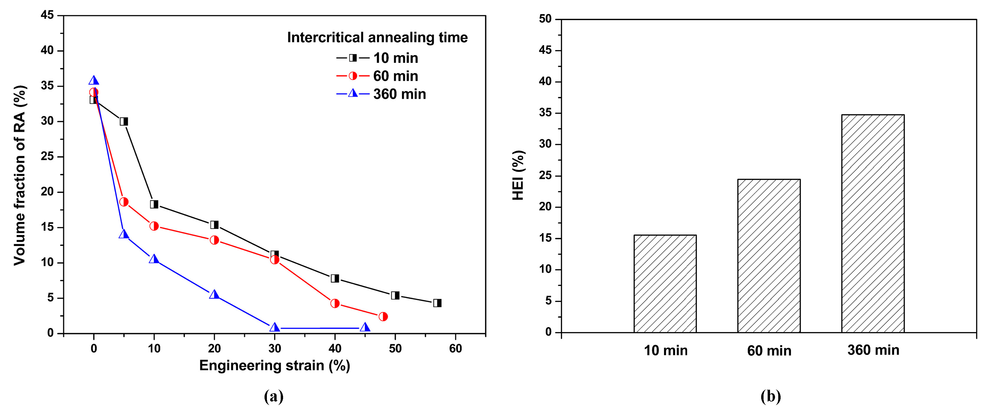
  • In general, the HE characteristics of medium–Mn steels are governed by the volume fraction and mechanical stability of retained austenite. Effective alloy and process design should target a sufficiently high fraction of retained austenite with a high mechanical stability and/or SFE, to avoid α′- or ε-martensitic transformation or even suppress planar slip. A finer grain size is often found to help mechanically stabilize the austenite.
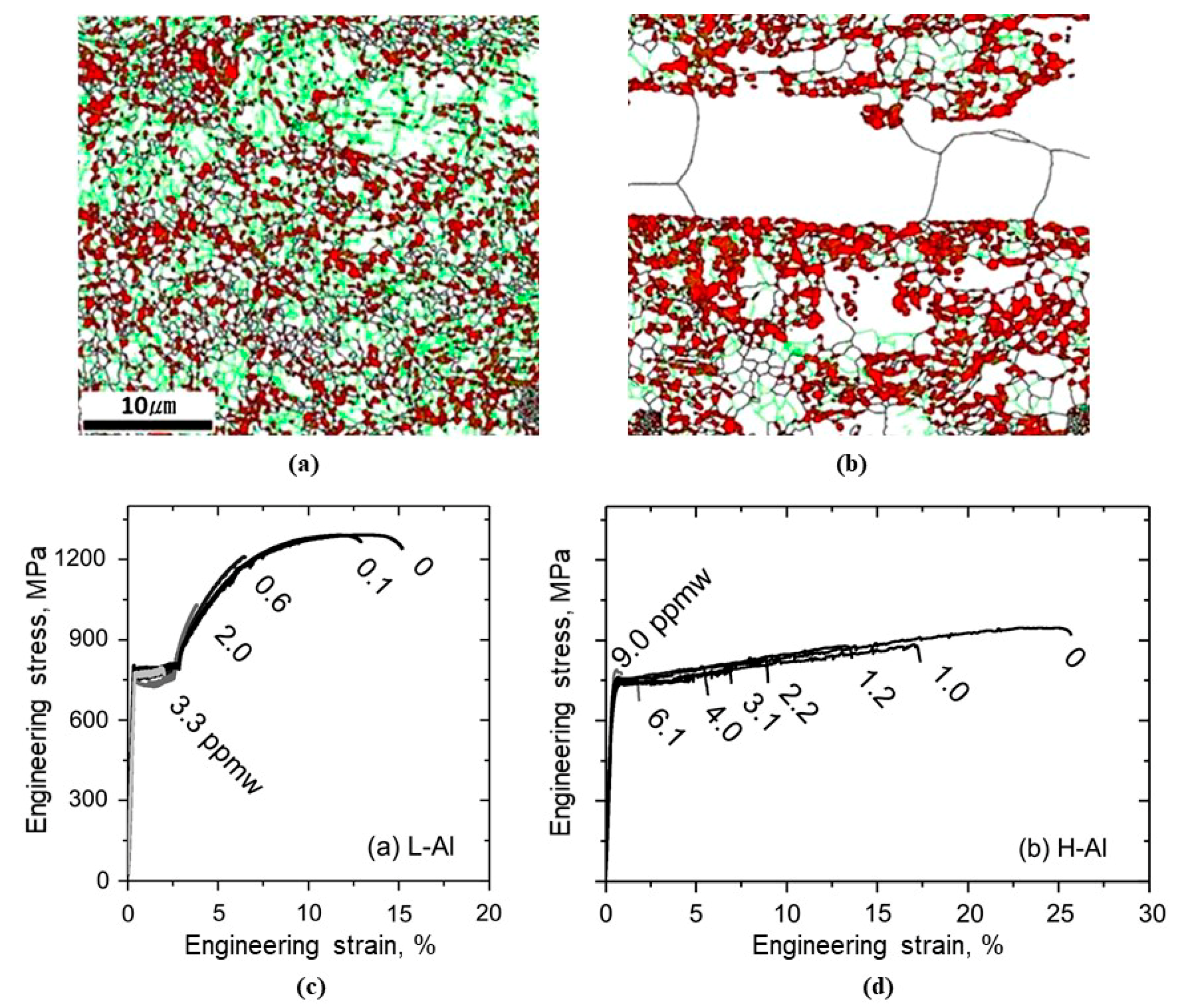
  • In theory, alloying elements that increase the SFE are expected to improve the HE resistance. C, Mn, Al, and Ni increase the SFE of austenite significantly. C is the most powerful in increasing SFE, but the amount is often limited below 0.6 wt pct, due to concerns related to the weldability or C segregation during casting [3]. Sufficiently high Al (≥3 wt pct) may be helpful to increase SFE of austenite, while stabilizing ferrite. Many investigations have focused on medium-Mn steels containing approximately 3 wt pct Al, as a greater amount of Al may cause difficulties during melting, secondary refining, and casting [3]. Cu appears to slightly increase SFE when in solid solution.
The analysis here indicates that alloy and process design for a H–resistant steel should aim to generate a sufficient amount of fine-grained austenite in the microstructure and, at the same time, the SFE of the austenite needs to be sufficiently high, to avoid α′- or ε-martensitic transformation or even suppress planar slip. A full transition in plasticity mechanism from TRIP to perfect dislocation glide and shear banding is noted in a duplex microstructure of relatively high-alloyed steels. For example, in the study by Yoo et al. [58], the Fe–0.8C–15Mn–7Al alloy for which plastic deformation in austenite is governed by dislocation glide exhibited generally high resistance to H–delayed fracture, comparable to or better than those of fully austenitic TWIP steels. One challenge with the design of an H–resistant duplex or multiphase steel exists in quantifying or predicting the mechanical stability of the austenite in a multiphase microstructure, as the chemical composition of the austenite significantly varies depending on the processing history, phase fraction, and solute partitioning behavior.
The current review of the existing studies on the HE of medium-Mn steels indicates that most studies are concerned with “H–delayed fracture”, associated with automotive applications. Therefore, the studies have exclusively employed SSRT of tensile specimens (most frequently of sheet-type) in H pre-charged conditions. Notably, fatigue, notch, or fracture toughness-type testing in H has not been performed for these types of microstructures. Considering the recent research efforts to expand their use beyond the automotive applications into the area of heavy steel plate for structural applications, future HE studies should also incorporate broad ranges of test specimen thickness and steel products, such as pipes and plates. In addition, future studies are needed to explore the mechanical performance of medium-Mn steel grades during long-term exposure and/or in H-containing gas atmospheres, which is not necessarily identical to behavior in laboratory testing after electrochemical charging.

5. Conclusions

This paper reviewed the current understanding of relationships between processing, microstructure, and HE characteristics of medium or intermediate Mn steels with multiphase microstructures. Many of the previous studies revealed that the H–resistance of medium–Mn steels depends substantially on the mechanical stability of retained austenite, since martensite formation decreases H–resistance. For a similar level of austenite mechanical stability, a microstructure with a higher austenite fraction is more resistant to HE. Effects of microstructural morphology on the severity of HE is not completely clear in the literature, as conflicting results have been reported. Therefore, the austenite morphology may be a secondary factor, compared to the austenite fraction and stability parameters. Limited information is available on the effect of micro alloy precipitation on the H–resistance of medium–Mn steel, except for the study by Park et al. [55], who argued that the effect of micro alloy precipitates, mostly formed in the ferritic regions, on the overall HE sensitivity was insignificant. Nevertheless, there remains a potential opportunity to employ precipitates (e.g., Cu–associated precipitates) for H trapping, as there are not a sufficient number of publications yet to clarify precipitate effects on the H–resistance of medium–Mn steel. Additionally, some microstructural refinement strategies, for example, using “warm rolling”, have been shown to significantly improve the resistance of the steel to H–induced cracking. The alloy and process design for H-resistant steel should aim to generate fine grained austenite in the microstructure, while the SFE of the austenite is as high as possible, to avoid α′– or ε–martensitic transformation or even suppress planar slip. Although C, Mn, Si, and Al are the most common alloying elements used in medium–Mn steel, other alloying elements that increase SFE or austenite stability should enhance the HE resistance.

Author Contributions

Conceptualization, L.C., J.G.S. and K.O.F.; investigation, L.C., Y.K., J.G.S. and K.O.F.; original draft preparation L.C.; review and editing L.C., Y.K., J.G.S. and K.O.F.; project administration J.G.S. and K.O.F.; and funding acquisition, J.G.S. and K.O.F. All authors have read and agreed to the published version of the manuscript.

Funding

The authors gratefully acknowledge the support from the US DOE Fuel Cells Technology Office and H2@Scale program, under award number DE-EE0008828. The authors also acknowledge the support of the sponsors of the Advanced Steel Processing and Products Research Center (ASPPRC) at the Colorado School of Mines.

Institutional Review Board Statement

Not applicable.

Informed Consent Statement

Not applicable.

Data Availability Statement

Data sharing not applicable.

Acknowledgments

The advice and feedback of ASPPRC sponsors are acknowledged.

Conflicts of Interest

The authors declare no conflict of interest.

References

  1. Miller, R. Ultrafine-grained microstructures and mechanical properties of alloy steels. Metall. Mater. Trans. B 1972, 3, 905–912. [Google Scholar] [CrossRef]
  2. Suh, D.-W.; Kim, S.-J. Medium Mn transformation-induced plasticity steels: Recent progress and challenges. Scr. Mater. 2017, 126, 63–67. [Google Scholar] [CrossRef]
  3. Hu, B.; Luo, H.; Yang, F.; Dong, H. Recent progress in medium-Mn steels made with new designing strategies, a review. J. Mater. Sci. Technol. 2017, 33, 1457–1464. [Google Scholar] [CrossRef]
  4. Lee, Y.-K.; Han, J. Current opinion in medium manganese steel. Mater. Sci. Technol. 2015, 31, 843–856. [Google Scholar] [CrossRef]
  5. Rana, R. Special Issue on ‘Medium Manganese Steels’; Taylor & Francis: Abingdon, UK, 2019. [Google Scholar]
  6. Hu, J.; Du, L.-X.; Dong, Y.; Meng, Q.-W.; Misra, R. Effect of Ti variation on microstructure evolution and mechanical properties of low carbon medium Mn heavy plate steel. Mater. Charact. 2019, 152, 21–35. [Google Scholar] [CrossRef]
  7. Hu, J.; Du, L.; Liu, H.; Sun, G.; Xie, H.; Yi, H.; Misra, R. Structure–mechanical property relationship in a low-C medium-Mn ultrahigh strength heavy plate steel with austenite-martensite submicro-laminate structure. Mater. Sci. Eng. A 2015, 647, 144–151. [Google Scholar] [CrossRef]
  8. Benzing, J.T.; da Silva, A.K.; Morsdorf, L.; Bentley, J.; Ponge, D.; Dutta, A.; Han, J.; McBride, J.R.; Van Leer, B.; Gault, B. Multi-scale characterization of austenite reversion and martensite recovery in a cold-rolled medium-Mn steel. Acta Mater. 2019, 166, 512–530. [Google Scholar] [CrossRef]
  9. Choi, Y.H.; Ryu, J.H.; Lee, S.W.; Lee, K.; Lee, B.J.; Kim, J.-K.; Lee, J.S.; Suh, D.-W. Influence of initial microstructures on intercritical annealing behaviour in a medium Mn steel. Mater. Sci. Technol. 2019, 35, 2092–2100. [Google Scholar] [CrossRef]
  10. Jeong, I.; Ryu, K.M.; Lee, D.G.; Jung, Y.; Lee, K.; Lee, J.S.; Suh, D.-W. Austenite morphology and resistance to hydrogen embrittlement in medium Mn transformation-induced plasticity steel. Scr. Mater. 2019, 169, 52–56. [Google Scholar] [CrossRef]
  11. Glover, A.; Gibbs, P.J.; Liu, C.; Brown, D.W.; Clausen, B.; Speer, J.G.; De Moor, E. Deformation behavior of a double soaked medium manganese steel with varied martensite strength. Metals 2019, 9, 761. [Google Scholar] [CrossRef] [Green Version]
  12. Speer, J.; Rana, R.; Matlock, D.; Glover, A.; Thomas, G.; De Moor, E. Processing variants in medium-Mn steels. Metals 2019, 9, 771. [Google Scholar] [CrossRef] [Green Version]
  13. Wang, M.-M.; Tasan, C.C.; Ponge, D.; Dippel, A.-C.; Raabe, D. Nanolaminate transformation-induced plasticity–twinning-induced plasticity steel with dynamic strain partitioning and enhanced damage resistance. Acta Mater. 2015, 85, 216–228. [Google Scholar] [CrossRef]
  14. De Moor, E.; Matlock, D.K.; Speer, J.G.; Merwin, M.J. Austenite stabilization through manganese enrichment. Scr. Mater. 2011, 64, 185–188. [Google Scholar] [CrossRef]
  15. Gibbs, P.; De Moor, E.; Merwin, M.; Clausen, B.; Speer, J.; Matlock, D. Austenite stability effects on tensile behavior of manganese-enriched-austenite transformation-induced plasticity steel. Metall. Mater. Trans. A 2011, 42, 3691–3702. [Google Scholar] [CrossRef]
  16. Suh, D.-W.; Park, S.-J.; Lee, T.-H.; Oh, C.-S.; Kim, S.-J. Influence of Al on the microstructural evolution and mechanical behavior of low-carbon, manganese transformation-induced-plasticity steel. Metall. Mater. Trans. A 2010, 41, 397. [Google Scholar] [CrossRef] [Green Version]
  17. Lee, S.; Shin, S.; Kwon, M.; Lee, K.; De Cooman, B.C. Tensile properties of medium Mn steel with a bimodal UFG α+ γ and coarse δ-ferrite microstructure. Metall. Mater. Trans. A 2017, 48, 1678–1700. [Google Scholar] [CrossRef]
  18. Suh, D.W.; Ryu, J.H.; Joo, M.S.; Yang, H.S.; Lee, K.; Bhadeshia, H. Medium-alloy manganese-rich transformation-induced plasticity steels. Metall. Mater. Trans. A 2013, 44, 286–293. [Google Scholar] [CrossRef] [Green Version]
  19. Lee, S.; Lee, S.-J.; Kumar, S.S.; Lee, K.; De Cooman, B. Localized deformation in multiphase, ultra-fine-grained 6 Pct Mn transformation-induced plasticity steel. Metall. Mater. Trans. A 2011, 42, 3638–3651. [Google Scholar] [CrossRef] [Green Version]
  20. Lee, S.; Estrin, Y.; De Cooman, B.C. Constitutive modeling of the mechanical properties of V-added medium manganese TRIP steel. Metall. Mater. Trans. A 2013, 44, 3136–3146. [Google Scholar] [CrossRef] [Green Version]
  21. Zhao, X.; Shen, Y.; Qiu, L.; Liu, Y.; Sun, X.; Zuo, L. Effects of intercritical annealing temperature on mechanical properties of Fe-7.9 Mn-0.14 Si-0.05 Al-0.07 C steel. Materials 2014, 7, 7891–7906. [Google Scholar] [CrossRef] [Green Version]
  22. Zhang, R.; Cao, W.; Peng, Z.; Shi, J.; Dong, H.; Huang, C. Intercritical rolling induced ultrafine microstructure and excellent mechanical properties of the medium-Mn steel. Mater. Sci. Eng. A 2013, 583, 84–88. [Google Scholar] [CrossRef]
  23. Hu, B.; He, B.; Cheng, G.; Yen, H.; Huang, M.; Luo, H. Super-high-strength and formable medium Mn steel manufactured by warm rolling process. Acta Mater. 2019, 174, 131–141. [Google Scholar] [CrossRef]
  24. Cai, M.; Huang, H.; Zuo, X.; Ding, H.; Stanford, N. Enhanced strength-ductility of medium Mn steel by quenching, partitioning and tempering. Mater. Sci. Technol. 2020, 36, 584–597. [Google Scholar] [CrossRef]
  25. Lee, S.; Kang, S.-H.; Nam, J.-H.; Lee, S.-M.; Seol, J.-B.; Lee, Y.-K. Effect of Tempering on the Microstructure and Tensile Properties of a Martensitic Medium-Mn Lightweight Steel. Metall. Mater. Trans. A 2019, 50, 2655–2664. [Google Scholar] [CrossRef]
  26. Seo, E.J.; Cho, L.; De Cooman, B.C. Application of quenching and partitioning processing to medium Mn steel. Metall. Mater. Trans. A 2015, 46, 27–31. [Google Scholar] [CrossRef] [Green Version]
  27. Ayenampudi, S.; Celada-Casero, C.; Sietsma, J.; Santofimia, M.J. Microstructure evolution during high-temperature partitioning of a medium-Mn quenching and partitioning steel. Materialia 2019, 8, 100492. [Google Scholar] [CrossRef]
  28. Thomas, G.; Speer, J.; Matlock, D.; De Moor, E.; Garza, L. Alloy design for fundamental study of quenched and partitioned steels. In Proceedings of the Materials Science & Technology (MS&T); ASM International: Columbus, OH, USA, 2011; pp. 552–567. [Google Scholar]
  29. Thomas, G.; De Moor, E.; Speer, J. Tensile properties obtained by Q&P processing of Mn-Ni steels with room temperature quench temperatures. In Proceedings of International Symposium on New Developments in Advanced High-Strength Sheet Steels; De Moor, E., Jun, H.J., Speer, J.G., Merwin, M., Eds.; AIST: Warrendale, PA, USA, 2013; pp. 153–165. [Google Scholar]
  30. Kim, W.; Kim, S.-J. Application of Room-temperature Quenching and Partitioning on Medium Mn Steel. In Proceedings of the Materials Science & Technology 2019, Portland, OR, USA, 29 September–3 October 2019. [Google Scholar]
  31. De Cooman, B.C.; Lee, S.J.; Shin, S.; Seo, E.J.; Speer, J.G. Combined intercritical annealing and Q&P processing of medium Mn steel. Metall. Mater. Trans. A 2017, 48, 39–45. [Google Scholar]
  32. Chang, Y.; Wang, C.; Zhao, K.; Dong, H.; Yan, J. An introduction to medium-Mn steel: Metallurgy, mechanical properties and warm stamping process. Mater. Des. 2016, 94, 424–432. [Google Scholar] [CrossRef]
  33. Rana, R.; Carson, C.; Speer, J. Hot forming response of medium manganese transformation induced plasticity steels. In Proceedings of the 5th CHS2 Conference, Toronto, ON, Canada, 31 May–3 June 2015; pp. 391–400. [Google Scholar]
  34. Speer, J.G.; Matlock, D.K.; Moor, E. Highlights of recent progress in automotive sheet steel development. In Proceedings of the Fifth Baosteel Biennial Academic Conference, Shanghai, China, 4–6 June 2013; pp. E59–E65. [Google Scholar]
  35. Cameron, B.; Koyama, M.; Tasan, C. Phase stability effects on hydrogen embrittlement resistance in martensite–reverted austenite steels. Metall. Mater. Trans. A 2019, 50, 29–34. [Google Scholar] [CrossRef]
  36. Han, J.; Nam, J.H.; Lee, Y.K. The mechanism of hydrogen embrittlement in intercritically annealed medium Mn TRIP steel. Acta Mater. 2016, 113, 1–10. [Google Scholar] [CrossRef]
  37. Shen, X.; Song, W.; Sevsek, S.; Ma, Y.; Hüter, C.; Spatschek, R.; Bleck, W. Influence of Microstructural Morphology on Hydrogen Embrittlement in a Medium-Mn Steel Fe-12Mn-3Al-0.05 C. Metals 2019, 9, 929. [Google Scholar] [CrossRef] [Green Version]
  38. Fielding, L.; Song, E.J.; Han, D.-K.; Bhadeshia, H.; Suh, D.-W. Hydrogen diffusion and the percolation of austenite in nanostructured bainitic steel. Proc. R. Soc. A Math. Phys. Eng. Sci. 2014, 470, 20140108. [Google Scholar] [CrossRef]
  39. Han, J.; da Silva, A.K.; Ponge, D.; Raabe, D.; Lee, S.-M.; Lee, Y.-K.; Lee, S.-I.; Hwang, B. The effects of prior austenite grain boundaries and microstructural morphology on the impact toughness of intercritically annealed medium Mn steel. Acta Mater. 2017, 122, 199–206. [Google Scholar] [CrossRef]
  40. McMahon, C., Jr. Hydrogen-induced intergranular fracture of steels. Eng. Fract. Mech. 2001, 68, 773–788. [Google Scholar] [CrossRef]
  41. Kameda, J.; McMahon, C. Solute segregation and hydrogen-induced intergranular fracture in an alloy steel. Metall. Trans. A 1983, 14, 903–911. [Google Scholar] [CrossRef]
  42. Wang, M.; Tasan, C.C.; Koyama, M.; Ponge, D.; Raabe, D. Enhancing hydrogen embrittlement resistance of lath martensite by introducing nano-films of interlath austenite. Metall. Mater. Trans. A 2015, 46, 3797–3802. [Google Scholar] [CrossRef]
  43. Du, Y.; Gao, X.; Lan, L.; Qi, X.; Wu, H.; Du, L.; Misra, R. Hydrogen embrittlement behavior of high strength low carbon medium manganese steel under different heat treatments. Int. J. Hydrog. Energy 2019, 44, 32292–32306. [Google Scholar] [CrossRef]
  44. Shao, C.; Hui, W.; Zhang, Y.; Zhao, X.; Weng, Y. Effect of intercritical annealing time on hydrogen embrittlement of warm-rolled medium Mn steel. Mater. Sci. Eng. A 2018, 726, 320–331. [Google Scholar] [CrossRef]
  45. Zhang, Y.; Shao, C.; Wang, J.; Zhao, X.; Hui, W. Intercritical annealing temperature dependence of hydrogen embrittlement behavior of cold-rolled Al-containing medium-Mn steel. Int. J. Hydrog. Energy 2019, 44, 22355–22367. [Google Scholar] [CrossRef]
  46. Wang, J.; Hui, W.; Xie, Z.; Wang, Z.; Zhang, Y.; Zhao, X. Hydrogen embrittlement of a cold-rolled Al-containing medium-Mn steel: Effect of pre-strain. Int. J. Hydrog. Energy 2020, 45, 22080–22093. [Google Scholar] [CrossRef]
  47. Liu, Q.; Yan, Y.; Xu, J.; Yang, S.; Li, J.; Su, Y.; Qiao, L. Effect of Prestrain on Hydrogen-Induced Delayed Cracking for Medium Mn Steels. J. Mater. Eng. Perform. 2020, 1–10. [Google Scholar] [CrossRef]
  48. Ryu, J.H.; Chun, Y.S.; Lee, C.S.; Bhadeshia, H.; Suh, D.W. Effect of deformation on hydrogen trapping and effusion in TRIP-assisted steel. Acta Mater. 2012, 60, 4085–4092. [Google Scholar] [CrossRef]
  49. Wang, Z.; Xu, J.; Li, J. Influence of microstructure on hydrogen embrittlement in hot-rolled medium Mn steels. Mater. Sci. Eng. A 2020, 139147. [Google Scholar] [CrossRef]
  50. Zhang, Y.; Hui, W.; Wang, J.; Lei, M.; Zhao, X. Enhancing the resistance to hydrogen embrittlement of Al-containing medium-Mn steel through heavy warm rolling. Scr. Mater. 2019, 165, 15–19. [Google Scholar] [CrossRef]
  51. Ryu, J.H.; Kim, D.-I.; Kim, H.S.; Bhadeshia, H.; Suh, D.-W. Strain partitioning and mechanical stability of retained austenite. Scr. Mater. 2010, 63, 297–299. [Google Scholar] [CrossRef]
  52. Kim, Y.M.; Han, H.N.; Bhadeshia, H.; Suh, D.-W. Hydrogen and aluminium in high-manganese twinning-induced plasticity steel. Scr. Mater. 2014, 80, 9–12. [Google Scholar]
  53. Song, E.J.; Bhadeshia, H.; Suh, D.-W. Interaction of aluminium with hydrogen in twinning-induced plasticity steel. Scr. Mater. 2014, 87, 9–12. [Google Scholar] [CrossRef] [Green Version]
  54. Koyama, M.; Akiyama, E.; Lee, Y.-K.; Raabe, D.; Tsuzaki, K. Overview of hydrogen embrittlement in high-Mn steels. Int. J. Hydrog. Energy 2017, 42, 12706–12723. [Google Scholar] [CrossRef]
  55. Park, T.M.; Kim, H.-J.; Um, H.Y.; Goo, N.H.; Han, J. The possibility of enhanced hydrogen embrittlement resistance of medium-Mn steels by addition of micro-alloying elements. Mater. Charact. 2020, 165, 110386. [Google Scholar] [CrossRef]
  56. Li, Y.; Li, W.; Min, N.; Liu, H.; Jin, X. Homogeneous elasto-plastic deformation and improved strain compatibility between austenite and ferrite in a co-precipitation hardened medium Mn steel with enhanced hydrogen embrittlement resistance. Int. J. Plast. 2020, 133, 102805. [Google Scholar] [CrossRef]
  57. Sun, B.; Krieger, W.; Rohwerder, M.; Ponge, D.; Raabe, D. Dependence of hydrogen embrittlement mechanisms on microstructure-driven hydrogen distribution in medium Mn steels. Acta Mater. 2020, 183, 313–328. [Google Scholar] [CrossRef]
  58. Yoo, J.; Jo, M.C.; Kim, D.W.; Song, H.; Koo, M.; Sohn, S.S.; Lee, S. Effects of Cu addition on resistance to hydrogen embrittlement in 1 GPa-grade duplex lightweight steels. Acta Mater. 2020, 196, 370–383. [Google Scholar] [CrossRef]
  59. Choi, J.H.; Jo, M.C.; Lee, H.; Zargaran, A.; Song, T.; Sohn, S.S.; Kim, N.J.; Lee, S. Cu addition effects on TRIP to TWIP transition and tensile property improvement of ultra-high-strength austenitic high-Mn steels. Acta Mater. 2019, 166, 246–260. [Google Scholar] [CrossRef]
  60. Kwon, Y.J.; Lee, T.; Lee, J.; Chun, Y.S.; Lee, C.S. Role of Cu on hydrogen embrittlement behavior in Fe–Mn–C–Cu TWIP steel. Int. J. Hydrog. Energy 2015, 40, 7409–7419. [Google Scholar] [CrossRef]
  61. Chou, S.; Tsai, W. Hydrogen embrittlement of duplex stainless steel in concentrated sodium chloride solution. Mater. Chem. Phys. 1999, 60, 137–142. [Google Scholar] [CrossRef]
  62. Tao, P.; Gong, J.; Wang, Y.; Jiang, Y.; Li, Y.; Cen, W. Characterization on stress-strain behavior of ferrite and austenite in a 2205 duplex stainless steel based on nanoindentation and finite element method. Results Phys. 2018, 11, 377–384. [Google Scholar] [CrossRef]
Figure 1. Schematic of representative thermo-mechanical processing routes for medium-Mn steels and the resulting microstructures. IA, intercritical annealing; ART, austenite-reverted transformation; Q&T, quenching and tempering; Q&P, quenching and partitioning; UFG, ultra–fine–grained; α′, α′–martensite; γ, austenite; α, α–ferrite; and δ, δ–ferrite.
Metals 11 00358 g001
Figure 2. Pseudo-binary phase diagrams for (a) Fe–6.0Mn–xC, (b) Fe–6.0Mn–1.5Al–xC, (c) Fe–6.0Mn–3.0Al–xC, and (d) Fe–6.0Mn–1.5Al–2.0Si–xC systems (all in wt pct). γ, austenite; α, α–ferrite; δ, δ–ferrite; and θ, cementite. Thermodynamic calculations were performed, using the Thermo-Calc® software with database of TCFE9.
Metals 11 00358 g002
Figure 3. TEM micrographs of (a) lamellarized and (b) equiaxed morphologies, produced by IA of hot-rolled and cold-rolled medium-Mn steels (Fe–7Mn–0.1C–0.5Si, in wt pct), respectively; αL and γL are lath–shaped (lamellarized) ferrite and retained austenite, respectively; αG and γG are globular-shaped (equiaxed) ferrite and retained austenite, respectively. (c) Thermal desorption analysis (TDA) curves of the specimens pre-charged with H under the same charging conditions. (d) Engineering stress–strain curves obtained by SSRT. Reproduced from Reference [36], with permission from Elsevier.
Metals 11 00358 g003
Figure 4. Effect of various H-charging conditions on SSRT properties of intercritically annealed medium-Mn steels (Fe–0.11C–7.2Mn–1.0Si, in wt pct) with (a) lamellarized (M900) and (b) equiaxed morphologies (M820). (c) H-induced elongation loss as a function of the diffusible H content. (d) Change of austenite fraction during tensile deformation. The specimen M900 was austenitized at 900 °C for 10 min, cooled to room temperature, and reheated to an IA temperature of 650 °C for 4 min. The specimen M820 was austenitized at 820 °C for 10 min, cooled to room temperature, and reheated to an IA temperature of 650 °C for 2 min. Reproduced from Reference [10], with permission from Elsevier.
Metals 11 00358 g004
Figure 5. (ac) Electron backscatter diffraction (EBSD) phase map for microstructures of a medium-Mn steel (Fe–0.01C–9Mn–3Ni–1.4Al, in wt pct). (a) As-quenched martensite (M). Austenite-reversion-treated microstructures consisting of martensite and austenite films with an average thickness of (b) 200 nm (MA200nm) and (c) 500 nm (MA500nm). (d) H–thermal–desorption analysis results for M and MA500nm steel samples. (e) Engineering stress–strain curves showing SSRT properties. In (d,e), corresponding microstructures with H are referred to as (M)H, (MA200 nm)H, and (MA500nm)H. Reproduced from Reference [42], with permission from Springer Nature.
Metals 11 00358 g005
Figure 6. HE index, represented by elongation loss (ELloss) due to H, and H concentration as a function of the volume fraction of retained austenite in a medium-Mn steel (Fe–0.065C–0.2Si–5.45–Mn, in wt pct). Figure reproduced from Reference [43], with permission from Elsevier.
Metals 11 00358 g006
Figure 7. (a) Variations in the volume fraction of retained austenite in a medium-Mn steel (Fe–0.2C–5.0Mn–0.6Si–3Al, in wt pct) as a function of engineering strain and hold time (10–360 min) at an IA temperature of 750 °C. (b) HE index (relative elongation loss due to H) evaluated by SSRT testing as a function of IA time. Reproduced from Reference [44], with permission from Elsevier.
Metals 11 00358 g007
Figure 8. EBSD phase maps for BCC (white) and FCC (red) of (a) low–Al/medium-Mn steel (L–Al: Fe–0.12C–4.6Mn–0.55Si–1.1Al, in wt pct) and (b) high-Al/medium-Mn steel (H–Al: Fe–0.12C–5.8Mn–0.47Si–3.1Al, in wt pct). (c) Engineering stress–strain curves of low-Al and (d) high-Al alloys pre-charged with an H concentration of 0 to 9 ppm, tested at a slow strain rate of 105 s−1. In (a,b), green and black lines indicate low-angle (misorientation of 2–15°) and high-angle (misorientation >15°) boundaries, respectively. Reproduced from Reference [48], with permission from Elsevier.
Metals 11 00358 g008
Figure 9. SEM fractographs of H–charged SSRT specimens of (a) an intercritically annealed and (b) an intercritically warm-rolled medium–Mn steel (Fe–0.20C–4.9Mn–3.1Al–0.6Si, in wt pct). Reproduced from Reference [50], with permission from Elsevier.
Metals 11 00358 g009
Figure 10. Three–dimensional atom probe tomography (3D–APT) maps for Ni, Al, Mn, and Cu in (a) the ferritic and (b) austenitic regions in a Cu-added steel (Fe–7Mn–2.5Ni–1.5Al–1.5Cu–0.01C, in wt pct). (c) Engineering stress–strain curves before and after H-charging in Cu-free (Fe–7Mn–2.5Ni–1.5Al–0.01C, in wt pct) and Cu-added steels. These two steels were two–stage annealed; the first IA was performed at 630 °C for 1 h, and the second step involved “tempering” at 500 °C. The hold times in the “tempering” step used for the Cu–free and Cu–added steels were 5 and 2 h, respectively. (d) Average hardness, measured by nano-indentation, of the ferrite (α) and austenite (γ) in the Cu-free and Cu-added steels. Reproduced from Reference [56], with permission from Elsevier.
Metals 11 00358 g010
Figure 11. (a) SEM fractograph of H–charged medium–Mn steel specimen with an equiaxed ferrite–austenite microstructure. (b) Enlargement of the area indicated by a yellow box in (a). Reproduced from Reference [36], with permission from Elsevier.
Metals 11 00358 g011
Figure 12. Comparison of H-induced cracks that formed in (ac) an intercritically annealed medium–Mn steel and (d) a 2205 duplex stainless steel, both tensile–tested during electrochemical H charging. Reproduced from References [49,61], with permission from Elsevier.
Metals 11 00358 g012
Table 1. Comparison of H-embrittlement (HE) characteristics of lamellarized versus equiaxed microstructures of medium-Mn steel, evaluated by means of slow strain rate testing (SSRT), at room temperature (α, α–ferrite; α′, α′–martensite; and γ, austenite).
Chemical Composition (wt.%)Product Type
or Starting Microstructure
Heat TreatmentMicrostructure (Morphology and Austenite Fraction)H content, wppm H-induced Elongation Loss, PctRemarksRef.
Fe-0.01C
-9Mn-3Ni-
1.4Al
Plate-type:
as-quenched martensite
IA or ART at 600 C for 8 hLamellarized
α′ + γ (33–36 vol pct)
1.87~92“Equiaxed” absorbed much greater H content for a given H-charging condition. Cameron et al. [35]
Cold-rolled,
martensite
IA at 600 °C for 1 h Equiaxed
α + γ (~40 vol pct)
15.6 ~91
Fe-0.1C-
7Mn-0.5Si
Hot-rolledIA at 640 °C for 30 minLamellarized
α′ + γ (47 vol pct)
~1.2~87“Equiaxed” had a higher ultimate tensile strength and was more H-resistant than lamellarized.Han
et al. [36]
Cold-rolledIA at 640 °C for 30 minEquiaxed
α + γ (50 vol pct)
~1.2~74
Fe-0.06C-
11.7Mn-2.9Al-0.2Si
Cold-rolledIA at 675 °C for 2 hLarger, mixed lamellarized and equiaxed
α + γ (55.2 vol pct)
3.1~58“Larger mixed” microstructure was more H-resistant than finer, lamellarized condition. Shen
et al. [37]
10.0~75
25.9~83
Cold-rolledAus. at 800 °C for 20 min + IA at 650 °C for 15 minFiner, lamellarized
α + γ (53.1 vol pct)
2.4~86
7.6~87
34.6~87
Fe-0.11C-
7.2Mn-1.0Si
Cold-rolledAus. at 900 °C for 10 min +
IA at 650 °C for 4 min
Lamellarized
α + γ (32 vol pct)
0.40“Lamellarized” was more H-resistant than equiaxed.
Tested with samples having similar austenite fraction and mechanical stability.
Jeong
et al. [10]
0.9~1
1.6~3
2.6~50
3.7~85
4.2~90
Cold-rolledAus. at 820 °C for 10 min +
IA at 650 °C for 2 min
Equiaxed
α + γ (32 vol pct)
0.5~38
1.5~54
2.0~75
3.4~95
4.1~98
4.4~98
Table 2. HE characteristics of Al– and Si–alloyed medium-Mn steels, evaluated by means of SSRT testing at room temperature (α, α–ferrite; α′, α′–martensite; γ, austenite; and δ, δ–ferrite).
Product TypeChemical Composition (wt.%) IA Temperature
/Hold Time
Microstructure (Morphology and Austenite Fraction)H Content, Wppm H-Induced Elongation Loss, PctAuthors’ InterpretationRef.
Cold-rolledFe-0.12C-
4.6Mn-
0.55Si-
1.1Al
720 °C/2 minEquiaxed
α + γ (26 vol%)
0.1~16HE is more pronounced for the low‑Al alloy containing less stable austenite.
Martensitic decomposition of the austenite leaves the inherited H in a more mobile state.
Ryu
et al. [48]
0.6~56
2.0~77
3.3~87
Fe-0.12C-
5.8Mn-
0.47Si-
3.1Al
780 °C/2 minEquiaxed
α + γ (30 vol%)
+ coarse δ
1.0~31
1.2~47
2.2~65
3.1~72
4.0~78
6.1~92
9.0~96
Hot-rolled Fe-0.22C-
6.1Mn-
3.1Al
740 °C/3 minLamellarized
α′ + γ (24.8 vol%)
3.913.5The presence of δ can promote Mn enrichment in reverted γ.
H-resistance increases with increasing stability and fraction of γ.
H-induced cracking occurs along the boundaries of δ and UFG regions.
Wang
et al. [49]
5.225.8
7.939.8
740 °C/30 minLamellarized
α′ + γ (37.4 vol%)
3.279.2
4.182.1
7.488.2
Fe-0.18C-
6.1Mn-
2.9Al-0.6Si
740 °C/3 minLamellarized
α′ + γ (15.2 vol%)
+ coarse δ
2.246.7
2.868.3
5.870.3
740 °C/30 minLamellarized
α′ + γ (31.4 vol%)
+ coarse δ
5.076.5
6.291.9
7.289.1
Warm-rolled at IA temperature0.20C-
5.0Mn-
3.0Al-0.6Si
750 °C/10 minEquiaxed
α + γ (33.1 vol%)
+ coarse δ
1.4~16HE became increasingly significant with increasing γ grain size.
H-resistance relates to the γ mechanical stability.
Shao
et al. [44]
750 °C/1 hEquiaxed
α + γ (34.2 vol%)
+ coarse δ
1.3~24
750 °C/6 hEquiaxed
α + γ (35.7 vol%) +
coarse δ
1.1~35
Hot-rolled0.20C-4.9Mn-3.1Al-0.6Si750 °C/1 hLamellarized
α′ + γ (~26 vol%) + coarse δ
0.9~78Warm rolling, i.e., fine lamellar structure, significantly enhances the H-resistance.Zhang
et al. [50]
750 °C/1 h + 89%‑reduction warm-rolled Fine, lamellarized
α + γ (~15 vol%)
+ coarse δ
1.6~28
Table 3. Fracture surface appearance and crack initiation sites of H–embrittled medium–Mn steels (α, α–ferrite; α′, α′–martensite; γ, austenite; and δ, δ–ferrite).
Chemical Composition (wt. %)Product TypeHeat TreatmentMicrostructure
(Austenite Fraction)
Fracture Surface Appearances and Crack Initiation SitesRefs.
Fe-0.1C-
7Mn-0.5Si
Hot-rolledIA at 640 °C
for 30 min
Lamellarized
α′ + γ (47 vol%)
Cracking along prior γ grain boundaries.
Rugged facets, likely associated with fracture of mechanically-induced α′.
Han
et al. [36]
Cold-rolledIA at 640 °C for 30 minEquiaxed α + γ (50 vol%)Dimples with granular features.The granular features are likely associated with intergranular cracking along equiaxed γ grain boundaries.
Fe-0.22C-
6.1Mn-3.1Al
Hot-rolledIA at 740 °C
for 3 min and 30 min
Lamellarized
α′ + γ (24.8–37.4 vol%)
Cracking preferentially along γ/α phase boundaries.
Cracking along prior γ grain boundaries or across the lamellar structure.
Wang et al. [49]
Fe-0.18C-
6.1Mn-2.9Al-0.6Si
Hot-rolledIA at 740 °C for 3 min and 30 minLamellarized
α′ + γ (15.2–31.4 vol%) + coarse δ
Cracking at the phase boundaries, preferentially along (γ or α)/δ phase boundaries.
0.20C-5.0Mn-3.0Al-0.6SiWarm-rolled at IA temperatureIA at 750 °C for 10 min, 1 h, and 6 hEquiaxed α + γ (33.1–35.7 vol%) + coarse δDimples with granular features.
The granular features likely associated with cracking in the region of mechanically-induced α′.
Shao et al. [44]
0.20C-4.9Mn-3.1Al-0.6SiHot-rolledIA at 750 °C for 1 hLamellarized
α′ + γ (~26 vol%)
+ coarse δ
Cracking across the lamellar structure or along γ/α′ phase boundaries.
A few cracks along prior γ grain boundaries.
Zhang
et al. [50]
IA at 750 °C for 1 h + 89% reduction warm rolledFine, lamellarized
α′ + γ (~15 vol%) + coarse δ
Micro-delamination cracking at γ/α′ interfaces along the rolling direction.
Larger-scale crack deflections near δ-ferrite layers.
Publisher’s Note: MDPI stays neutral with regard to jurisdictional claims in published maps and institutional affiliations.

