Article

The Weld Microstructure and Mechanical Properties of the Alloy 52 and Its Variants with Applied Electromagnetic Stirring during Welding

Nuclear Fuels and Materials Division, Institute of Nuclear Energy Research, Taoyuan 32546, Taiwan
*
Author to whom correspondence should be addressed.
Metals 2021, 11(2), 351; https://doi.org/10.3390/met11020351
Submission received: 16 January 2021 / Revised: 9 February 2021 / Accepted: 12 February 2021 / Published: 19 February 2021
(This article belongs to the Section Metal Casting, Forming and Heat Treatment)

Abstract

:
This study investigated the impact of electromagnetic stirring (EMS) on nickel-base alloy welds prepared with the gas tungsten arc welding process. Alloy 52 and its variants, Alloy 52M and Alloy 52MSS, were carefully evaluated with their weld microstructure and mechanical properties. The results showed that the welds exhibited a typical microstructure of dendrites, and that the dendrites could be refined by electromagnetic stirring. Meanwhile, with an application of EMS, the precipitates became smaller and more evenly distributed in the inter-dendritic areas. Ti(N,C)s, Nb/(Nb,Si)Cs, and large-scale Laves phase with (Nb,Mo,Ti)Cs were the precipitates present in the Alloy 52, Alloy 52M, and Alloy 52MSS welds, respectively. With the refined microstructure, both Alloy 52 and Alloy 52M welds were observed to have an increase in their tensile strength, with a decrease in their elongations. Comparatively, for the Alloy 52MSS weld, the tensile strength was enhanced along with a slight increase in elongation. Deep and dense dimples were a dominant feature of low-Nb-additions welds, and dendrite-like features were found prevalent among the Alloy 52MSS welds. With EMS, the dimples of Alloy 52 welds and the dendrite-like features of Alloy 52MSS welds became finer, while the dimples of Alloy 52M welds grew coarser.

1. Introduction

Alloy 52, a weld alloy with a Cr content up to 30-wt%, has superior resistance to intergranular stress corrosion cracking (IGSCC) and is often used for repairing the degraded Alloy 82/182 welds in nuclear power plants [1,2,3,4]. However, the high susceptibility of Alloy 52 to ductility dip cracking (DDC) during weld repairing is a technical concern [5,6,7].
In spite of the concern of IGSCC, Alloy 182 is less susceptible to DDC. This is attributed to the moderate addition of Nb, resulting in tortuous grain boundaries, and abundant coarse Nb precipitates on the grain boundary to block the initiation and propagation of DDC [8,9,10]. On this account, Alloy 52M was developed to mitigate DDC by adding 0.5–1.0 wt% of Nb to Alloy 52 [11]. The benefits of Nb additions include not only the reduction of Cr-depleted zone to increase the intergranular-corrosion (IGC) resistance, but also the enhancement of high-temperature strength [12,13]. That is because Nb has a strong affinity for carbon atoms to form niobium-carbides/carbonitrides. To further mitigate the DDC phenomenon, Alloy 52MSS was developed by increasing the Nb and Mo contents to 2.5 wt% and 4.0 wt% [8], respectively. It was noted that the additions of Nb and Mo enhanced the resistance of Alloy 52MSS weld to DDC and its mechanical properties, however its solidification cracking is still a concern [14,15,16,17]. Despite its susceptibility to hot cracking, Alloy 52MSS has become an alternative filler metal to Alloy 52M for repairing components in nuclear power plants [11].
Electromagnetic stirring (EMS) is used for stabilizing the arc of gas tungsten arc welding (GTAW) and plasma welding [18]. EMS improves the solidification microstructure, as a result bettering the mechanical properties of welds [18,19,20,21,22]. The most useful frequency of EMS is 7 Hz for nickel-based alloys. The grain refinement and the improvement of DDC resistance of Alloy 52 are significant [23,24].
Although EMS has been studied for many years, limited work has been done on its application to Alloy 52 M and Alloy 52 MSS. In this study, Alloy 52 and its variants, Alloy 52 M and Alloy 52 MSS, were investigated. The effects of EMS on the microstructure and mechanical properties were characterized and evaluated. The interaction between EMS and Nb/Mo additions was discussed as well.

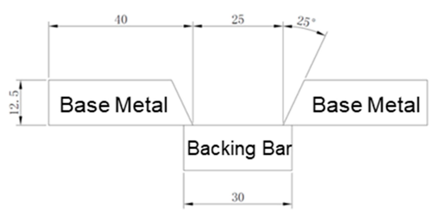
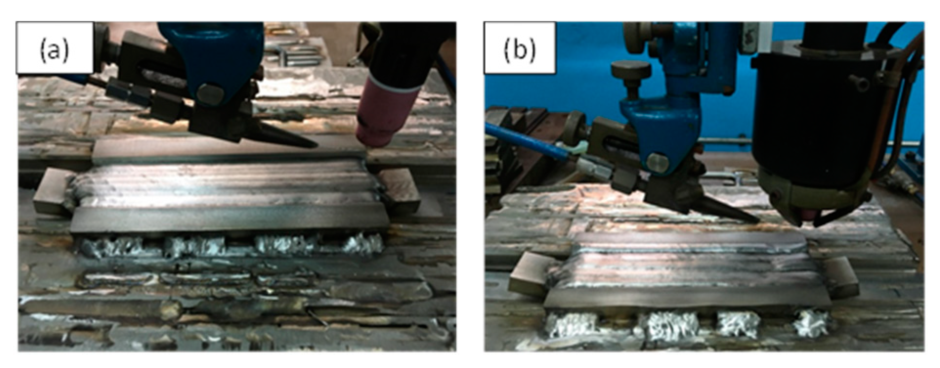
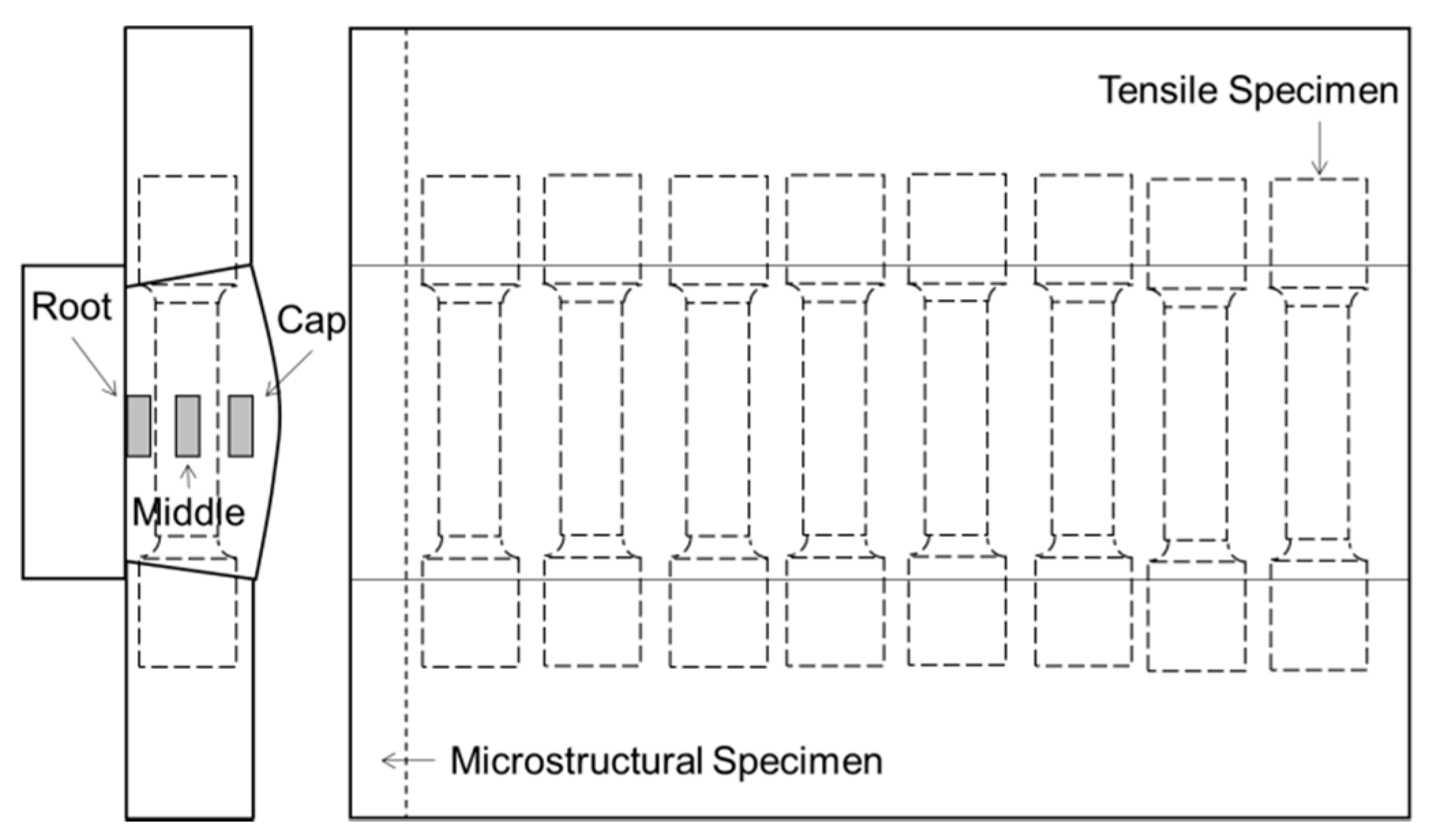
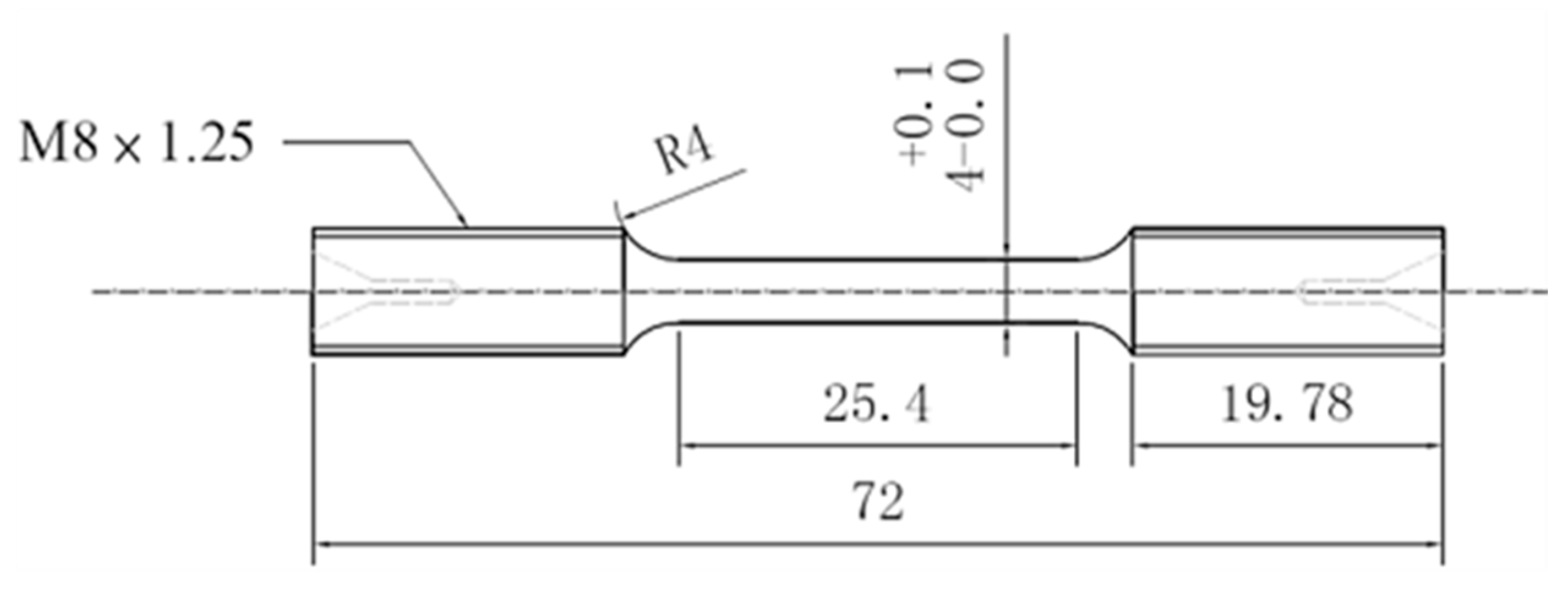
2. Materials and Methods

Alloy 82/182 dissimilar welds normally join two different base metals, one of which is stainless steel 304. In this study, 304 L plates were used for the base metals and backing bars with 400 × 40 × 12.5 mm3, and 400 × 30 × 12.5 mm3 in dimension, respectively. The schematic diagram of the weldment is presented in Figure 1. The weld metals are Alloy 52, Alloy 52M and Alloy 52MSS, with a diameter of 0.9 mm. Table 1 gives the compositions of the base metal and filler metals.
Gas tungsten arc welding (GTAW) was performed with a linear welding machine, equipped with EMS, as shown in Figure 2. The base metals were cleaned with alcohol and then placed on the fixture. Table 2 shows the welding parameters. Both visual and radiographical tests were conducted to examine the welding defects in the welds. The specimens were then sampled for microstructural characterization and mechanical properties evaluation.
The samples for microstructural characterization were prepared following the standard metallographic procedures—cutting, grinding, and polishing processes. The samples were electrolytically etched with a solution of 70 mL H3PO4 + 30 mL H2O under 6~10 V DC for 3~4 s.
The weld microstructure was examined with an optical microscope (OM, Olympus Corporation, Tokyo, Japan). Microstructural characterization and compositional analysis were performed with a scanning electron microscope (SEM, JEOL Ltd., Tokyo, Japan) equipped with an energy dispersive spectroscope (EDS, Oxford Instruments, Abingdon, UK) and an electron backscatter diffraction (EBSD, Oxford Instruments, Abingdon, UK) system. The positions for microstructural characterization are shown in Figure 3.
The micro-hardness measurements were taken with a load of 300 g for 10 s. Each of the hardness values for the middle and cap regions of the welds was averaged by more than 15 indents, at a distance of 0.25 mm between each two indentations. In the cap re-gion, the last indentation to the edge was at least a distance of 0.5 mm.
Uniaxial tensile tests were conducted with an MTS810 testing machine (MTS Systems Corporation, Eden Prairie, MN, USA) at a nominal strain rate of 3 × 10⁻⁴ /s at room tem-perature. The tensile specimens were prepared according to ASTM-E8M as shown in Figure 4. The fracture surface of the tested tensile specimen was further observed by SEM. The effects of EMS on the welds were then discussed based on the results of mechanical tests, fractographic examinations, and microstructural characterization.

3. Results and Discussion

3.1. Microstructural Observation

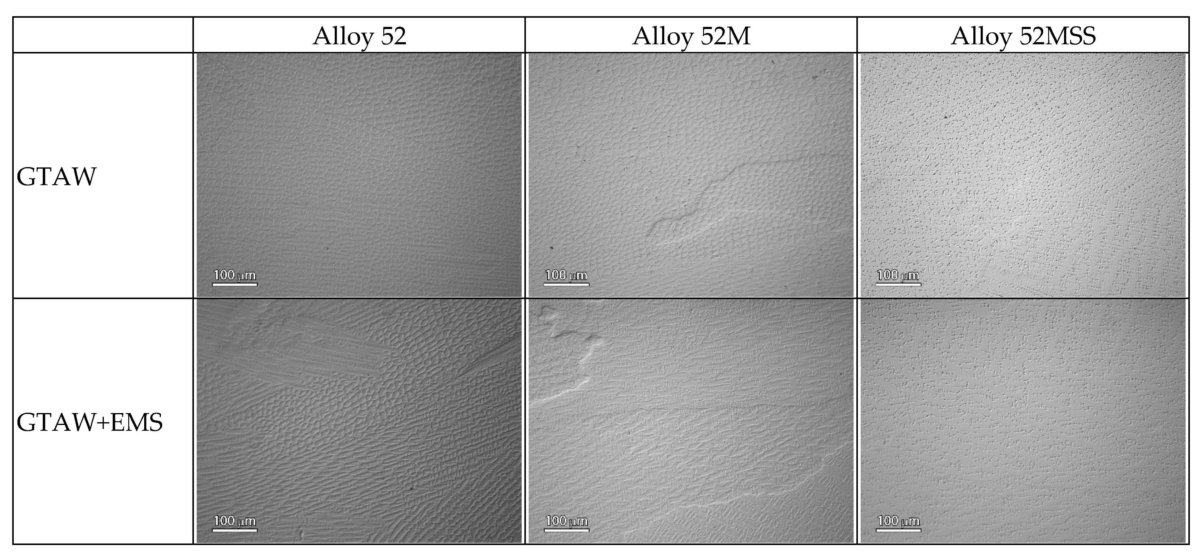
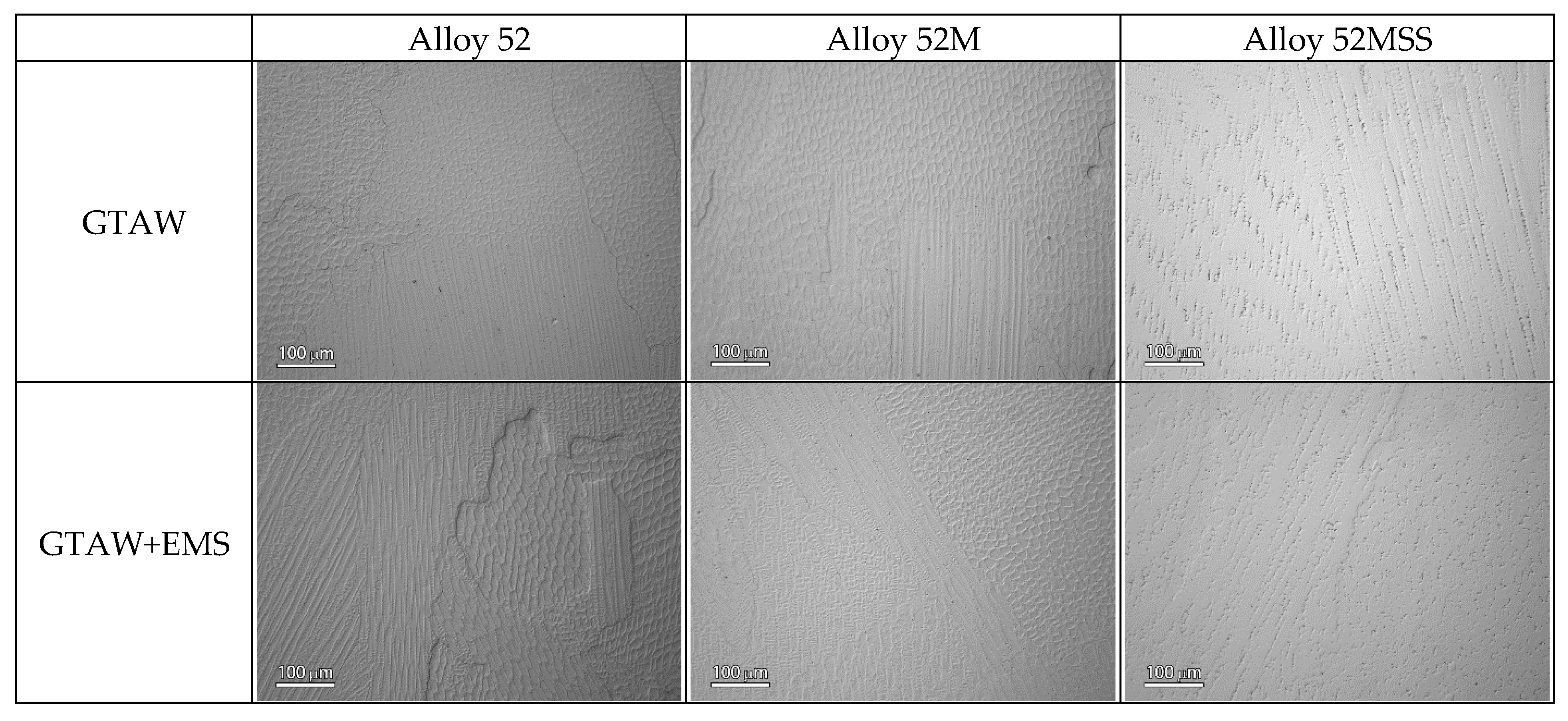
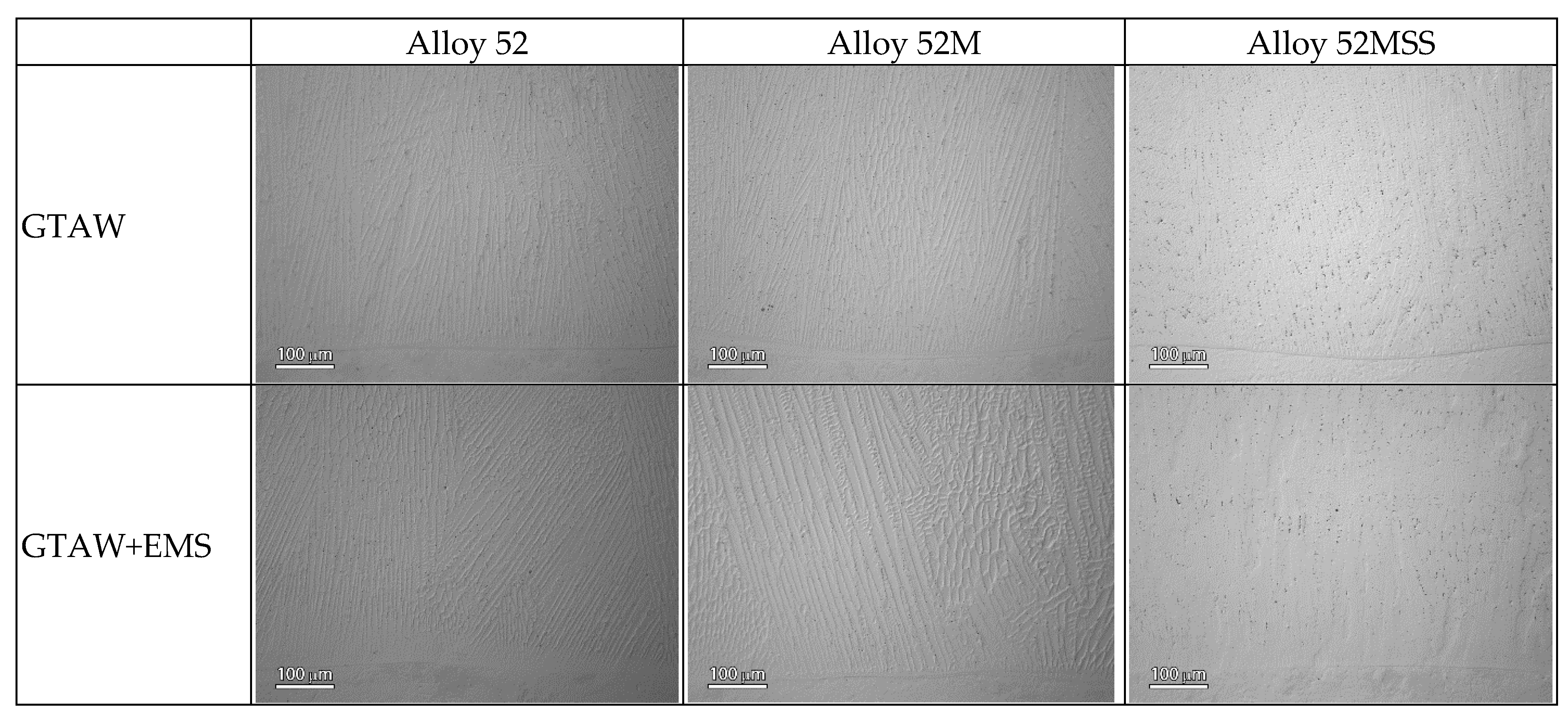
3.1.1. The OM Observation

Figure 5 shows the OM micrographs of the cap in the welds. The welds obtained without an application of EMS were dominated with the microstructural feature of irregular cellular dendrites. Those welds formed under applied EMS had dendrites with a growth direction affected by the electromagnetic field. Among these welds, only Alloy 52MSS welds had a lot of coarse precipitates in the inter-dendritic areas and their dendrites were with secondary dendrite arm spacing (SDAS).
In the middle region, all the welds possessed a mixture of columnar and cellular dendrites, as shown in Figure 6. Under the influence of EMS, the columnar dendrites were affected by the electromagnetic field, leading to the formation of fragmented dendrites. Alloy 52MSS welds had many precipitates in the inter-dendritic areas.
Columnar dendrites were the dominant feature of the root region for all welds, as shown in Figure 7. With an application of EMS, the columnar dendrites structures shortened as could be seen in those in the middle region. The dendrites in Alloy 52M and Alloy 52MSS welds are coarser than those in Alloy 52 welds. Upon the influence of EMS, the precipitates of Alloy 52MSS welds became significantly finer and sparser.
Although Alloy 52M welds have a moderate amount of Nb, their microstructure is more or less the same as that of Alloy 52 welds with no Nb content. Alloy 52MSS welds containing a large amount of Nb and Mo show lots of precipitates present in the inter-dendritic areas.

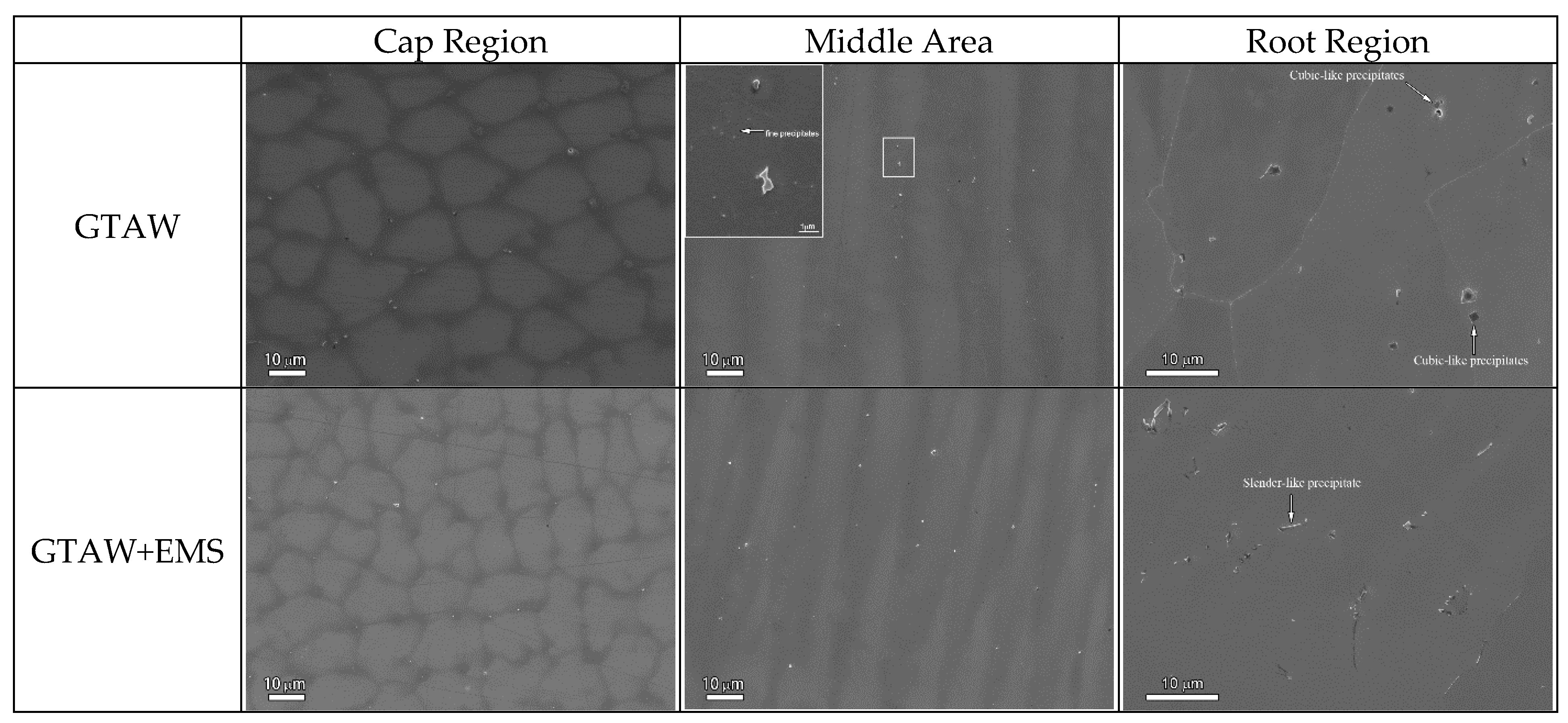
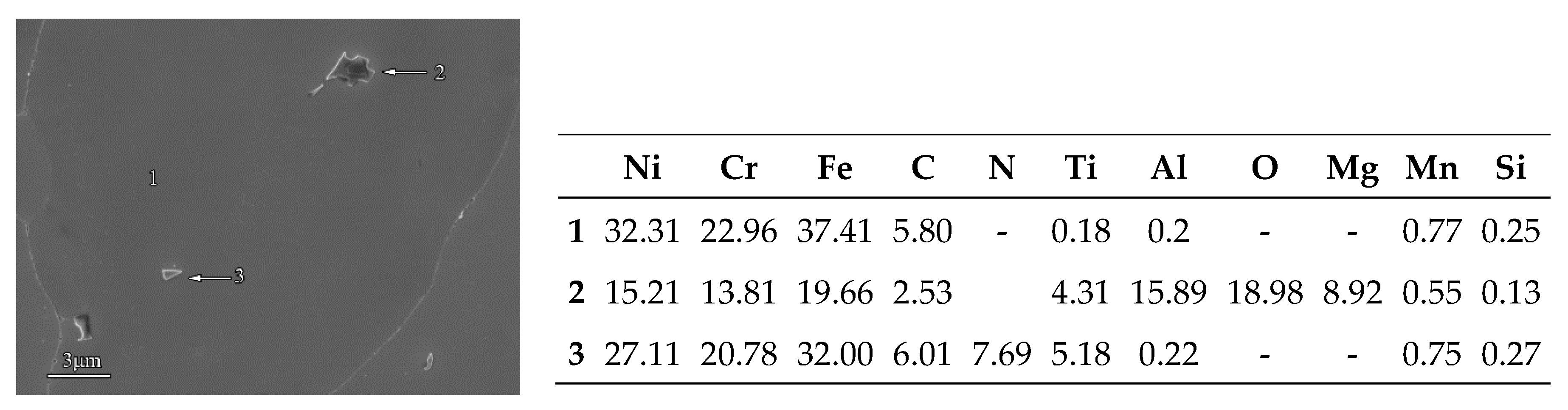
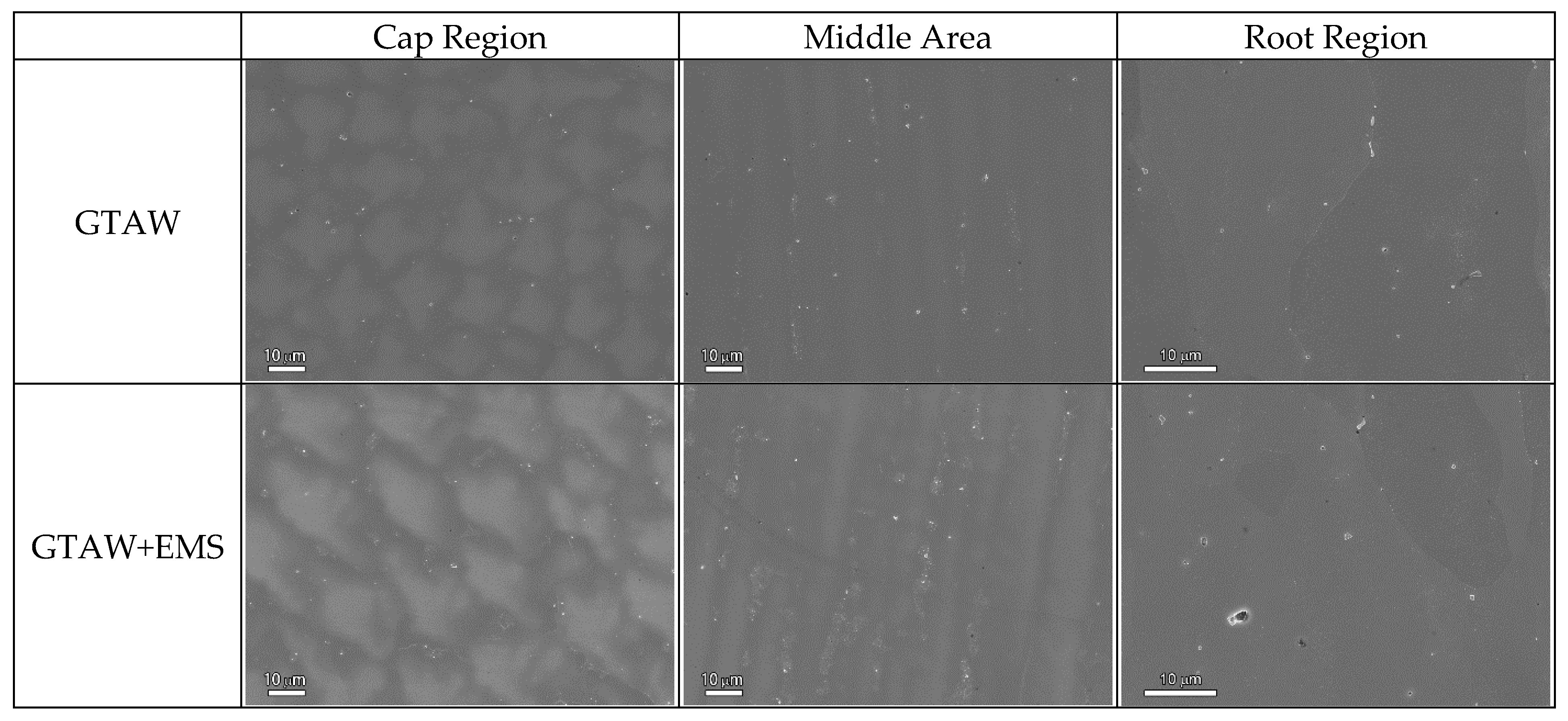
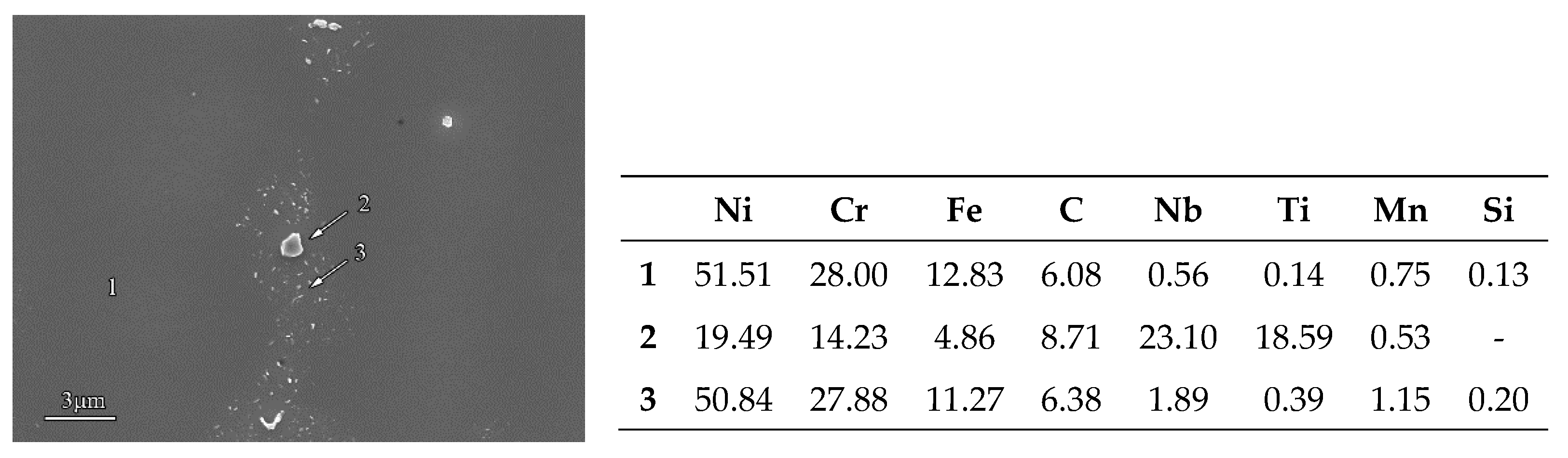
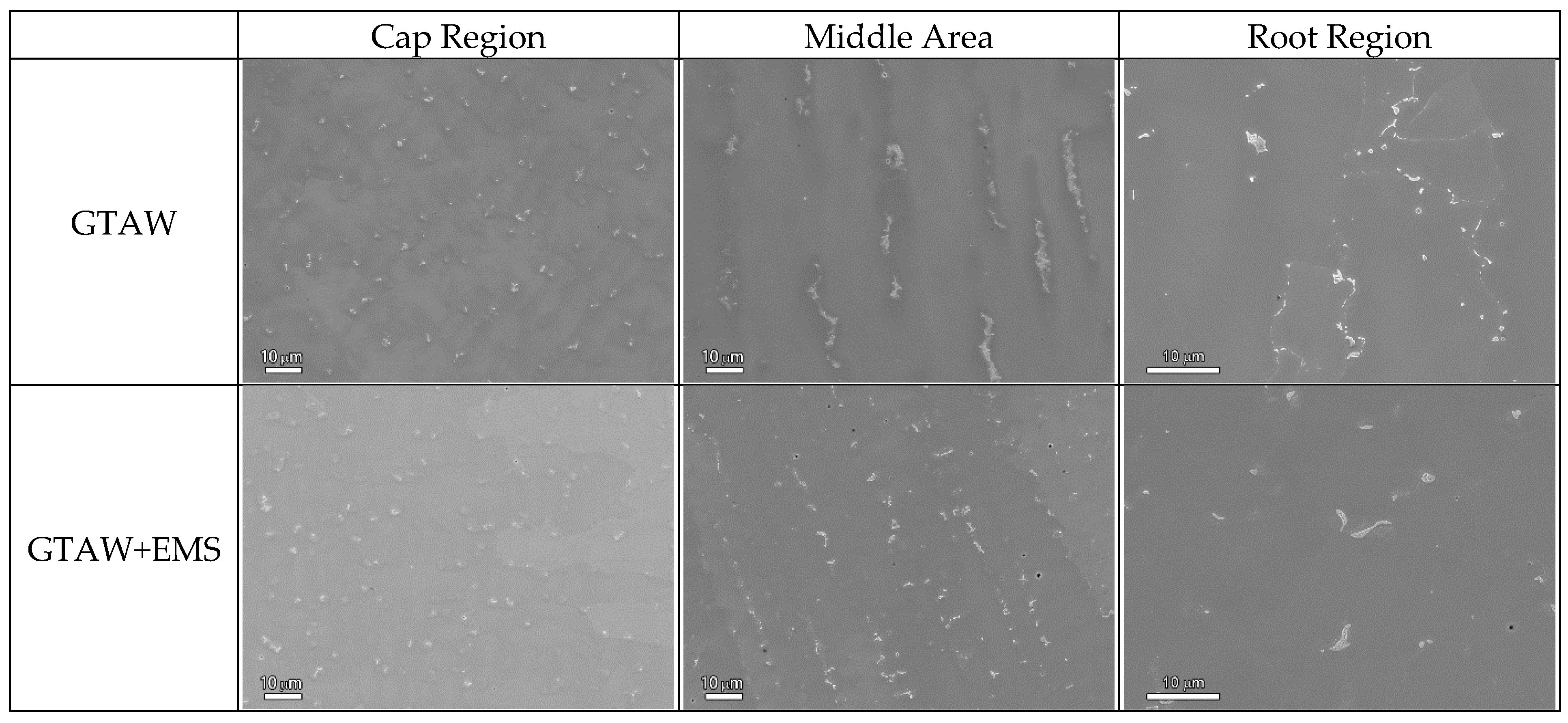
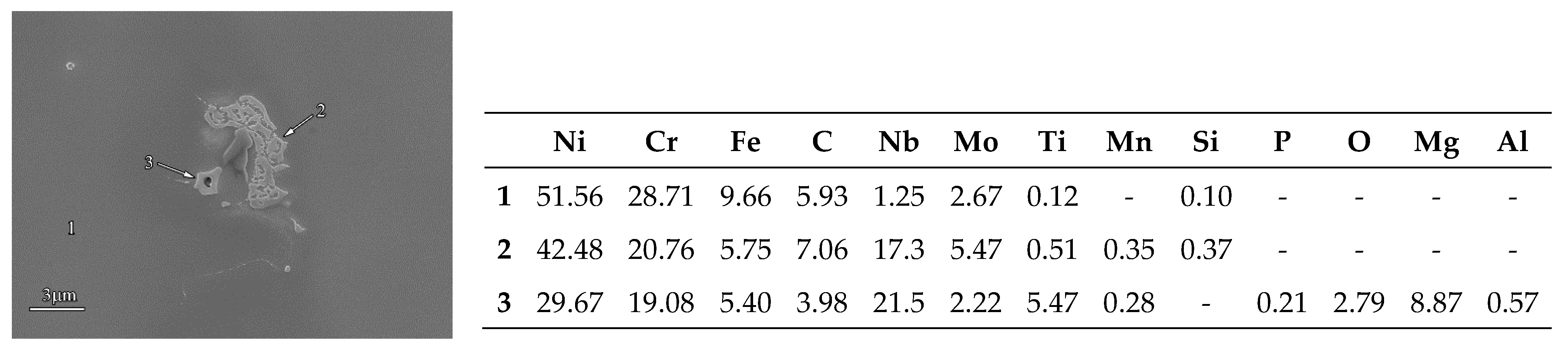
3.1.2. SEM Observation and EDS Analysis

Figure 8 shows the SEM micrographs of Alloy 52 welds. Without EMS, cellular dendrites were the dominant microstructure in the cap region. There were precipitates with a length of about 600 nm to 1 μm in the inter-dendritic areas. In the middle region, some precipitates between dendrites were larger than 1μm in length. It was also feasible to see fine precipitates of about 50 nm to 150 nm in size precipitated nearby. In the root, the cubic-like precipitates were mostly distributed along the dendrites.
For the welds made with EMS applied, the cellular dendrites observed in the cap region were more random and denser, as presented in Figure 8. Despite their sizes at the same level, the precipitates were more evenly distributed in the welds made with EMS applied than those without EMS applied. In the middle region, the cellular dendrites were smaller, and the columnar dendrites shorter. In the root region, the grain boundary cannot be clearly discerned, and the precipitates in the inter-dendritic areas were slender and in a discontinuous island-like shape.
The compositional analysis shows that the precipitates in the Alloy 52 weld are Ti(N,C)s. In some cases, Ti(N,C)s are mixed with Al-Mg oxides, as shown in Figure 9. In the root region, the precipitates comprising Ti(N,C)s and Al-Mg oxides were much bigger and darker, while those containing TiNs/TiCs smaller.
In Alloy 52M welds, the dominant microstructure of the cap regions was also cellular dendrites with the precipitates, about 400 nm to 1 μm in size, in the inter-dendritic areas. In the middle region, there were coarse precipitates surrounded with an abundance of tiny ones in the inter-dendritic area. In the root, some of the coarse precipitates were along the grain boundary, and the others were on the columnar dendrites and in the inter-dendritic areas, as presented in Figure 10.
In Alloy 52M weld, the precipitates are mainly composed of Nb/(Nb,Ti)Cs, some of which mixed with Al-Mg oxides. Beside the large Nb/(Nb,Ti)Cs, there were many tiny precipitates with sizes below 400 nm. According to the EDS analysis, Figure 11, they are Nb/(Nb,Si)Cs as well. In the root region, the coarse and slender precipitates are mainly comprised of Nb/(Nb,Ti)Cs. Like those in the cap region, some precipitates are Nb/(Nb,Ti)Cs mixed with Al-Mg oxides. Some cubic (Nb,Ti)Ns were also observed in the root region.
In the cap region of Alloy 52MSS welds, the dendrites were irregular. There were many precipitates, around 1~3 μm in size, distributed between the cellular dendrites. In the middle region, there were a large number of coarse island-like precipitates, about 6μm in size, in the inter-dendritic areas. They were the largest of all. In the root region, the precipitates were coarse-grained, as revealed in Figure 12. In Alloy 52MSS weld, the large phases are (Ni,Cr,Fe)2(Nb,Mo,Si) according to the compositional analysis. These large phases are thought to be Laves phases [25]. There are also some tiny (Nb,Mo,Ti)Cs, as shown in Figure 13.
With an application of EMS, the dendrites of all welds became denser. The fine precipitates, i.e., TiN/Cs in Alloy 52 welds, and NbCs/(Nb,Si)Cs in Alloy 52M/52MSS welds were evenly distributed in the inter-dendritic areas. The cap region was a little different in the microstructure from the middle region. There were many tiny precipitates in the middle region, but none in the cap region. This could result from welding thermal cycling that induces the fine precipitates in the middle region. In the cap region, a rapid cooling rate could inhibit the formation of tiny precipitates.
Both Alloy 52 and Alloy 52M welds were characterized by a microstructure of cellular dendrites (Figure 5, Figure 6 and Figure 7). With the EMS applied, the dendrites of Alloy 52 welds grew finer, but those of Alloy 52M became coarser. A discussion on the phenomena observed with Alloy 52M welds is given below. In Alloy 52MSS welds (Figure 12), the precipitates are noted to become finer with EMS, except for the cap region.
It has been indicated that EMS could refine the grains and compositional segregation of welds [18,19,23,24,26]. With grain refinement, there will be more interdendritic regions with smaller area. Therefore, this helps the large precipitates to reduce in size and distribute more evenly. Besides, welding heat would prompt NbCs/(Nb,Si)Cs to precipitate in inter-dendritic regions. It is also known that Mo could induce more Nb-carbides [27,28]. With more inter-dendritic regions and Nb/Mo additions, Alloy 52MSS would have even more Nb-carbides when EMS applied.

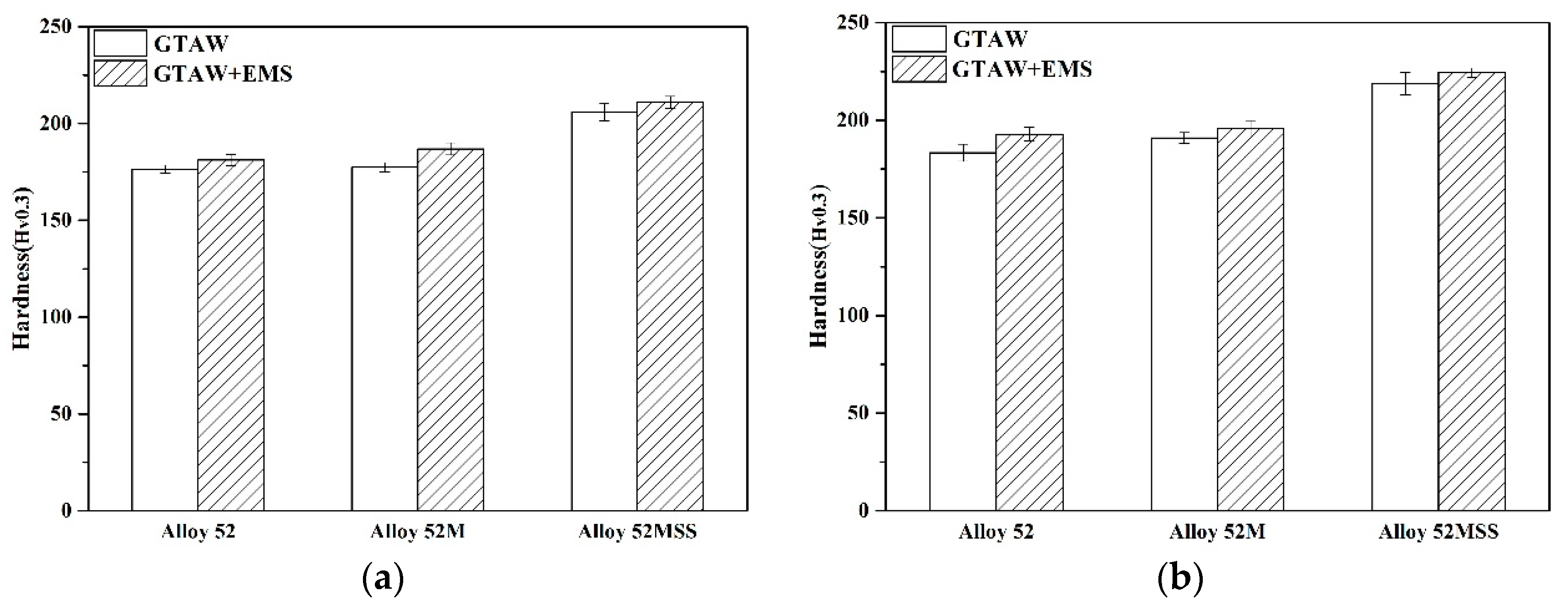
3.2. Hardness Measurement
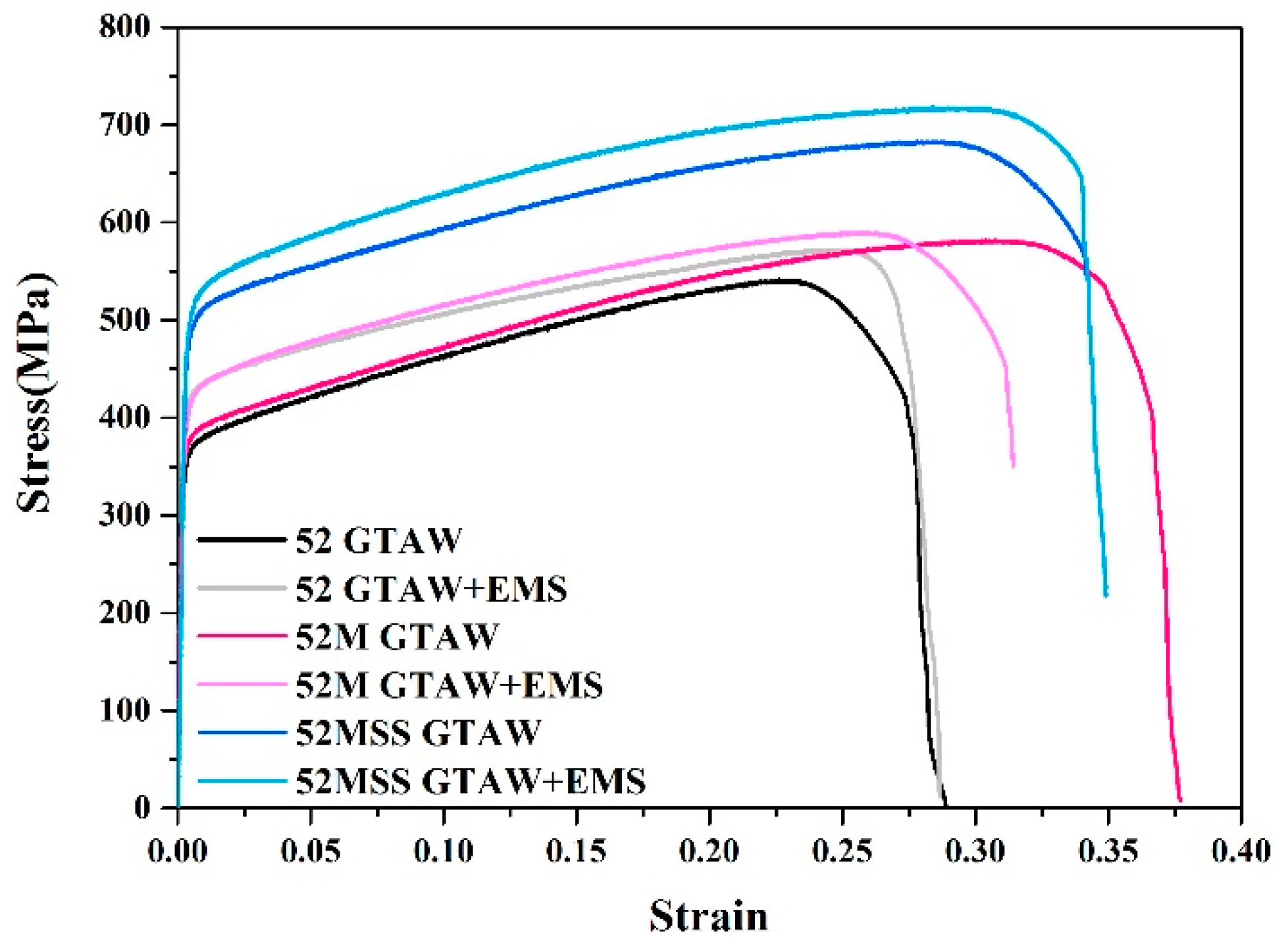
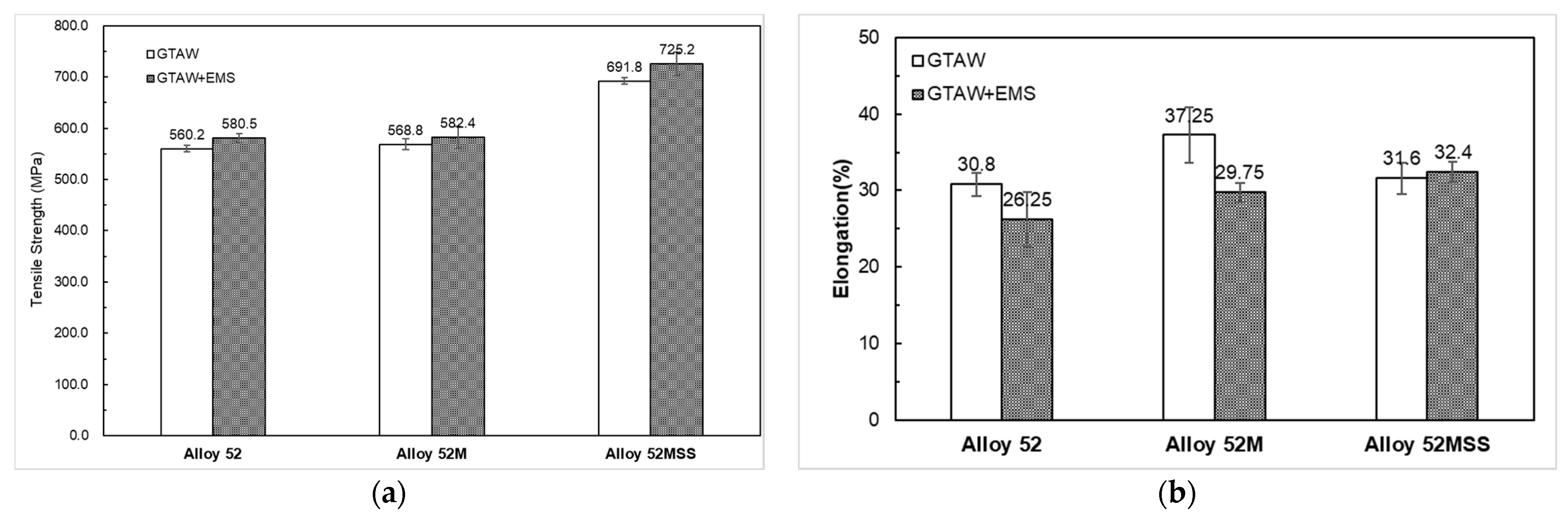
Figure 14 shows the average micro-hardness measurements for the cap and middle regions. The hardness of Alloy 52 welds is similar to that of Alloy 52M welds. Alloy 52MSS welds have the largest hardness measurement of all the welds for their highest Nb and Mo contents. It also shows that the average hardness in the middle region is slightly higher than that for the cap of all welds.
The hardness measurements of all welds were improved by EMS, which could be attributed to the denser dendrites and even precipitate distribution.

3.3. Tensile Test

The tensile tests were conducted on the specimens machined from the middle region of the welds. Figure 15 shows the stress-strain curves tested at room temperature. It shows that the tensile strength and yield strength of all specimens increased with an application of EMS. Among all the specimens, Alloy 52MSS welds with EMS had the highest ultimate tensile strength and yield strength. This could be ascribed to the highest Nb and Mo additions that induced the greatest precipitation strengthening of tiny precipitates and Laves phases. However, Alloy 52 and Alloy 52M have relatively small difference in ultimate tensile strength, because of their small difference in Nb additions.
Figure 16a shows the averaged tensile strength of three tests for each specimen. It was found that the average tensile strength for all specimens was enhanced with an application of EMS. This could result from modifications to the microstructures of dendrites and precipitates by EMS.
Figure 16b shows the averaged elongation measurements for all specimens. Alloy 52M weld had the highest elongation. Except for Alloy 52MSS, the others decreased in elongation with EMS applied. This could be attributed to the fragmented dendritic structures. The microstructural characterization demonstrates that the dendrites were originally continuous; however, they were fragmented by EMS, thereby resulting in the decrease of the tensile elongation of weld specimen. EMS had no influence on the elongation of Alloy 52MSS welds, because it makes little or no difference in change of modification to their microstructure.
Figure 17 presents the SEM fractographs of all tested specimens. Ductile dimples were the dominant fracture features. The low-Nb-additions welds exhibited deep and dense dimples. With an application of EMS, the dimples of Alloy 52 welds became finer, while those on Alloy 52M welds grew coarser.
The dendrite-like features were found in the Alloy 52MSS welds without EMS applied. Their dimples were shallower and sparser than those of Alloy 52/52M welds. Moreover, there were many Nb-Mo rich precipitates at the bottom of dimples. The SEM fractographs show that the dendrites became finer with EMS applied.

4. Conclusions

  • The welds of Alloy 52 variants exhibited a typical microstructure of dendrites. Alloy 52 and Alloy 52M with a moderate amount of Nb were similar in the dendrites of the welds, while Alloy 52MSS welds showed lots of precipitates present in the interdendritic areas containing a large amount of Nb and Mo. With an application of EMS, the dendrites became shorter and denser, and the precipitates were evenly distributed in the dendritic area.
  • Under the effect of EMS, the fine TiNs/TiCs and NbCs/(Nb,Ti)Cs were evenly distributed in the Alloy 52 and Alloy 52M welds, respectively. For Alloy 52MSS, the Laves phases and (Nb,Mo,Ti)Cs became significantly finer, leading to the enhancement of its hardness.
  • The hardness measurements of all welds were improved by EMS. Of all welds, the average hardness in the middle region was slightly higher than that for the cap, and Alloy 52MSS welds had the largest hardness measurement.
  • The tensile test results show that dense dendritic structure and even distribution of tiny precipitates contributed to the improvement of tensile strength of the welds made with EMS employed. While, with the exception of Alloy 52MSS, the elongation measurements of the welds decreased because of the dendrites fragmented by EMS.
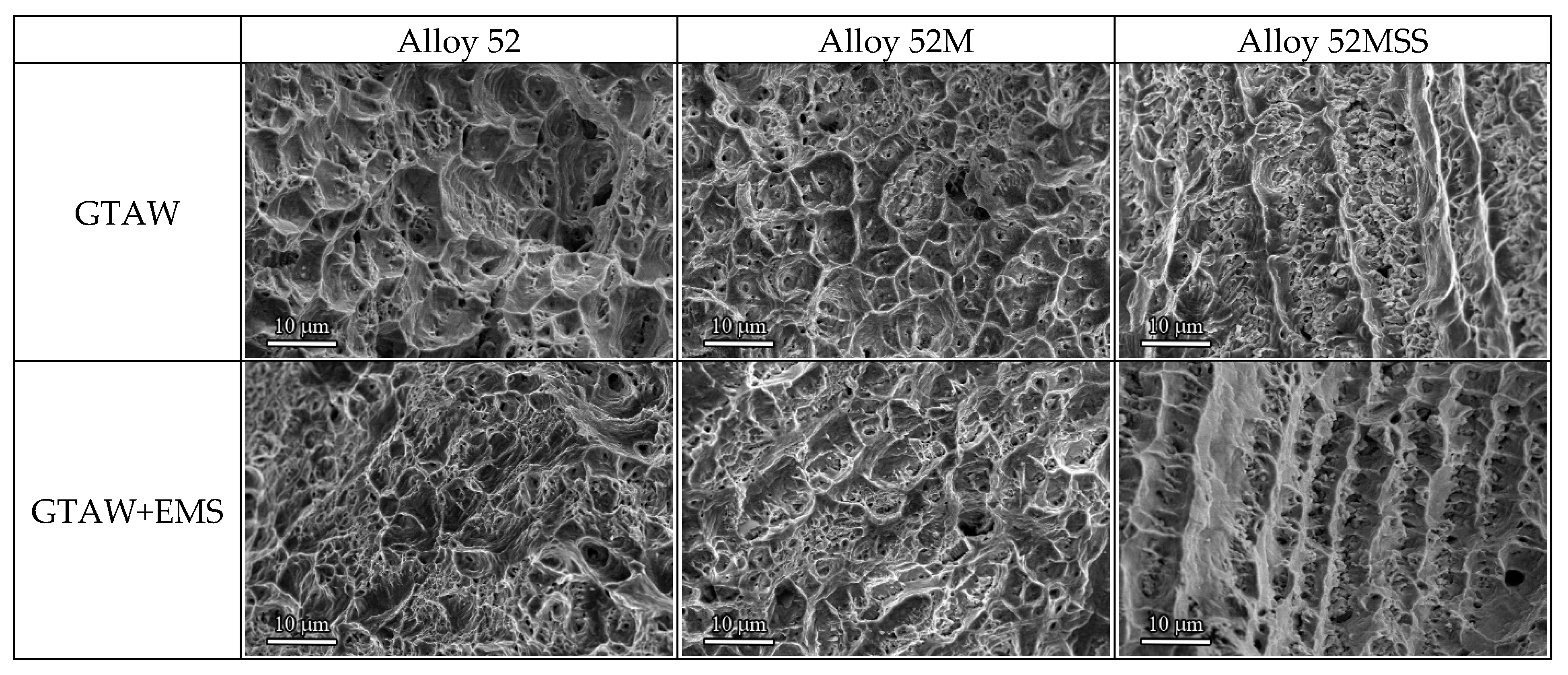
  • The fractographic observations showed that ductile dimples were the dominant fracture feature of all tested welds, and that the dimples of Alloy 52MSS were shallower and sparser. For all the welds prepared with an application of EMS, shallower dimples were the representative fracture feature of all specimens, which could be related to the discontinuous dendritic structure.

Author Contributions

The contributions of all authors are provided as follows. Investigation, T.-J.W.; methodology, T.-J.W. and S.-L.J.; validation, S.-L.J. and J.-Y.H.; writing—original draft preparation, T.-J.W.; writing—review and editing, S.-L.J. and J.-Y.H. All authors have read and agreed to the published version of the manuscript.

Funding

This research received no external funding.

Institutional Review Board Statement

Not applicable.

Informed Consent Statement

Not applicable.

Data Availability Statement

The data used to support the findings of this study are available from the corresponding authors upon reasonable request.

Conflicts of Interest

The authors declare no conflict of interest.

References

  1. Grimmel, B.; Cullen, W.H., Jr. U.S. Plant Experience with Alloy 600 Cracking and Boric Acid Corrosion of Light-Water Reactor Pressure Vessel Materials; U.S. Nuclear Regulatory Commission: Washington, DC, USA, 2005. [Google Scholar]
  2. Bamford, W. A review of alloy 600 cracking in operating nuclear plants: Historical experience and future trends. In Proceedings of the 11th International Conference on Environmental Degradation of Materials in Nuclear Power Systems–Water Reactor, Stevenson, Washington, DC, USA, 10–14 August 2003. [Google Scholar]
  3. Scott, M.; Combrade, P. On the mechanism of stress corrosion crack initiation and growth in alloy 600 exposed to PWR primary water. In Proceedings of the 11th International Conference on Environmental Degradation of Materials in Nuclear Power Systems–Water Reactor, Stevenson, Washington, DC, USA, 10–14 August 2003. [Google Scholar]
  4. Bamford, W.; Hall, J. Cracking of alloy 600 nozzle welds in pwrs: Review of cracking events and repair service experience. In Proceedings of the 12th International Conference on Environmental Degradation of Materials in Nuclear Power System—Water Reactors, Salt Lake City, UT, USA, 14–18 August 2005. [Google Scholar]
  5. Kiser, S.; Zhang, R.; Baker, B. A new welding material for improved resistance to ductility dip cracking. In ASM Proceedings of International Conference on Trends in Welding Research; Citeseer: Pine Mountain, GA, USA, 2008. [Google Scholar]
  6. Available online: https://www.nrc.gov/docs/ML1015/ML101590585.pdf (accessed on 10 January 2021).
  7. Available online: https://www.nrc.gov/docs/ML1116/ML111661838.pdf (accessed on 10 January 2021).
  8. Lippold, J.C.; Nissley, N.E. Ductility-dip cracking in high chromium, Ni-base filler metals. In Hot Cracking Phenomena in Welds II; Springer: Berlin/Heidelberg, Germany, 2008; pp. 409–425. [Google Scholar]
  9. Young, G.A.; Capobianco, T.E.; Penik, M.A.; Morris, B.W.; McGEE, J.J. The Mechanism Of Ductility Dip Cracking in Nickel-Chromium Alloys. Weld J. 2008, 87, 31s–43s. [Google Scholar]
  10. Ramirez, A.J.; Sowards, J.W.; Lippold, J.C. Improving the ductility-dip cracking resistance of Ni-base alloys. J. Mater. Process. Technol. 2006, 179, 212–218. [Google Scholar] [CrossRef]
  11. International Atomic Energy Agency. Dissimilar Metal Weld Inspection, Monitoring and Repair Approaches; IAEA-TECDOC-1852; IAEA: Vienna, Austria, 2018. [Google Scholar]
  12. Horn, R.M.; Ford, F.P.; Cowan, R.L. Experience and assessment of stress corrosion cracking in L-grade stainless steel BWR internals. Nucl. Eng. Des. 1997, 174, 313–325. [Google Scholar] [CrossRef]
  13. Jeng, S.L.; Lee, H.T.; Rehbach, W.P.; Kuo, T.Y.; Weirich, T.E.; Mayer, J.P. Effects of Nb on the microstructure and corrosive property in the Alloy 690–SUS 304L weldment. Mater. Sci. Eng. A 2005, 397, 229–238. [Google Scholar] [CrossRef]
  14. Jeng, S.L.; Chang, Y.H. Microstructure and flow behavior of Ni-Cr-Fe welds with Nb and Mo additions. Mater. Sci. Eng. A 2013, 560, 343–350. [Google Scholar] [CrossRef]
  15. Jeng, S.L.; Lee, H.T.; Huang, J.Y.; Kuo, R.C. Effects of Nb on the microstructure and elevated-temperature mechanical properties of alloy 690-SUS 304L dissimilar welds. Mater. Trans. 2008, 49, 1270–1277. [Google Scholar] [CrossRef] [Green Version]
  16. Zhang, X.; Li, D.Z.; Li, Y.Y.; Lu, S.P. Effect of Nb and Mo on the microstructure, mechanical properties and ductility-dip cracking of Ni-Cr-Fe weld metals. Acta Metall. Sin. (Engl. Lett.) 2016, 29, 928–939. [Google Scholar] [CrossRef] [Green Version]
  17. Yushchenko, K.; Savchenko, V.; Chervyakov, N.; Zvyagintseva, A.; Guyot, E. Comparative hot cracking evaluation of welded joints of alloy 690 using filler metals Inconel® 52 and 52 MSS. Weld. World 2011, 55, 28–35. [Google Scholar] [CrossRef]
  18. Wu, H.; Chang, Y.; Lu, L.; Bai, J. Review on magnetically controlled arc welding process. Int. J. Adv. Manuf. Technol. 2017, 91, 4263–4273. [Google Scholar] [CrossRef]
  19. Saini, S.; Gupta, V.; Nagpal, R.; Gupta, R.; Kuday, V. A review on the effect of magnetic field on weld quality and weld geometry in arc welding. Int. J. Adv. Educ. Res. 2017, 2, 57–63. [Google Scholar]
  20. Wagner, S.; Dugan, S.; Stubenrauch, S.; Jacobs, O. Modification of the grain structure of austenitic welds for improved ultrasonic inspectability. In Proceedings of the 38th MPA-Seminar 2012 Power Generation and Energy Efficiency Materials and Component Behaviour, Stuttgart, Germany, 1–2 October 2012; p. 607. [Google Scholar]
  21. Sivaprasad, K.; Raman, S.G.S. Influence of magnetic arc oscillation and current pulsing on fatigue behavior of alloy 718 TIG weldments. Mater. Sci. Eng. A 2007, 448, 120–127. [Google Scholar] [CrossRef]
  22. Zhang, G.; Shi, Y.; Zhu, M.; Fan, D. Arc characteristics and metal transfer behavior in narrow gap gas metal arc welding process. J. Mater. Process. Technol. 2017, 245, 15–23. [Google Scholar] [CrossRef]
  23. Lim, Y.C.; Yu, X.; Cho, J.H.; Sosa, J.; Farson, D.F.; Babu, S.S.; McCracken, S.L.; Flesner, B. Effect of magnetic stirring on grain structure refinement: Part 1 – Autogenous nickel alloy welds. Sci. Technol. Weld. Join. 2010, 15, 583–589. [Google Scholar] [CrossRef]
  24. Lim, Y.C.; Yu, X.; Cho, J.H.; Sosa, J.; Farson, F.D.; Babu, S.S.; McCracken, S.; Flesner, B. Effect of magnetic stirring on grain structure refinement Part 2-Autogenous nickel alloy welds. Sci. Technol. Weld. Join. 2010, 15, 400–406. [Google Scholar] [CrossRef]
  25. Andrade, T.F.; Kliauga, A.M.; Plaut, R.L.; Padilha, A.F. Precipitation of Laves phase in a 28%Cr–4%Ni–2%Mo–Nb superferritic stainless steel. Mater. Charact. 2008, 59, 503–507. [Google Scholar] [CrossRef]
  26. Chen, R.; Yang, Y.; Wang, Q.; Ding, H.; Su, Y.; Guo, J. Dimensionless parameters controlling fluid flow in electromagnetic cold crucible. J. Mater. Process. Technol. 2018, 255, 242–251. [Google Scholar] [CrossRef]
  27. Pan, H.; Ding, H.; Cai, M.; Kibaroglu, D.; Ma, Y.; Song, W. Precipitation behavior and austenite stability of Nb or Nb–Mo micro-alloyed warm-rolled medium-Mn steels. Mater. Sci. Eng. A 2019, 766, 138371. [Google Scholar] [CrossRef]
  28. Pan, H.; Ding, H.; Cai, M. Microstructural evolution and precipitation behavior of the warm-rolled medium Mn steels containing Nb or Nb-Mo during intercritical annealing. Mater. Sci. Eng. A 2018, 736, 375–382. [Google Scholar] [CrossRef]
Figure 1. Welding configuration.
Metals 11 00351 g001
Figure 2. Welding equipment: (a) GTAW and (b) GTAW+EMS.
Metals 11 00351 g002
Figure 3. The sampling positions of microstructural observations and tensile tests.
Metals 11 00351 g003
Figure 4. Dimensions of tensile test specimen.
Metals 11 00351 g004
Figure 5. Micrographs of welds in the cap.
Metals 11 00351 g005
Figure 6. Micrographs of welds in the middle.
Metals 11 00351 g006
Figure 7. Micrographs of welds in the root.
Metals 11 00351 g007
Figure 8. scanning electron microscope (SEM) micrographs of Alloy 52.
Metals 11 00351 g008
Figure 9. Compositions of precipitates in the GTAW welds of Alloy 52.
Metals 11 00351 g009
Figure 10. SEM micrographs of Alloy 52M.
Metals 11 00351 g010
Figure 11. Compositions of precipitates in the GTAW+EMS welds of Alloy 52M.
Metals 11 00351 g011
Figure 12. Scanning electron microscope (SEM) micrographs of Alloy 52MSS.
Metals 11 00351 g012
Figure 13. Compositions of precipitates in the GTAW welds of Alloy 52MSS.
Metals 11 00351 g013
Figure 14. The average hardness measurements: (a) cap, and (b) middle region.
Metals 11 00351 g014
Figure 15. Tensile stress-strain curves for the welds tested at room temperature.
Metals 11 00351 g015
Figure 16. Average results of tensile tests: (a) tensile strength, and (b) elongation.
Metals 11 00351 g016
Figure 17. Fractographs of tensile specimens.
Metals 11 00351 g017
Table 1. Chemical compositions of base metal and filler metals (wt%).
Base/ Weld MetalsNiCrFeMnNbMoTiCSiCuAlPSCoBZrTi+AlNb+Ta
SS304L8.0518.15Bal.1.60-0.09-0.0180.420.20-0.0320.004-----
Alloy 5260.0030.008.400.70-0.010.600.0300.170.010.640.0100.002---1.200.03
Alloy 52M59.2029.688.860.760.940.110.170.0240.100.030.120.0030.0010.010.0050.0020.290.94
Alloy 52MSS53.9529.029.050.722.533.900.030.0200.220.010.140.0050.0080.030.0040.010.172.53
Table 2. The welding parameters.
Arc Current (A)Arc Voltage (V)Welding Speed (mm/min)Wire Feed Rate (mm/min)EMS Frequency (Hz)
180~118010007 Hz
Publisher’s Note: MDPI stays neutral with regard to jurisdictional claims in published maps and institutional affiliations.

