1. Introduction
Laser welding is a method that employs a laser beam to join pieces of metal or thermoplastics. It has several advantages over the tungsten inert gas (TIG) [
1] and metal inert gas (MIG) [
2] welding techniques when dealing with metals: (a) high thermal power focused in a small spot (in the range of hundred microns) is resulting in high penetration area over a small surface, (b) the seam is minimized due to the low heat input, producing welds with an excellent visual aspect, (c) the method is contact-free and easily automatable and (d) allows joining of dissimilar materials [
3]. However, laser welding presents various drawbacks such as high equipment cost, complex beam positioning due to the small size of the spot, partial incompatibility with industrial metals such as Al or Cu (more than 90% reflectivity for infrared laser beams) [
4].
Aluminum (Al) is one of the metals (Al, Cu, Ni, Cr, Ti and Zn) that forms a natural oxide layer on its surface. This layer protects it against corrosion in harsh environments. Moreover, Al is lighter than iron and has a lower melting temperature and a higher thermal conductivity, making it desirable for various industrial sectors [
5]. Currently, after iron, Al is the second commonly used metal in the industry [
6,
7,
8,
9]. Its alloys have low weight and excellent mechanical properties. It is the reason for their use in the manufacturing of car bodies [
10,
11], ships [
12,
13], aircraft and space shuttles components [
14]. Aluminum magnesium-3 (AlMg3) has a high resistance to corrosion in salted medium and is commonly used in the manufacturing of ships, fuel tanks and chemical agents′ containers. During processing, hydrogen from the environmental humidity or different contaminants, can be captured in the AlMg3 welding structure, because it is soluble in liquid aluminum and insoluble in the solid-state alloy. The fast solidification of AlMg3 makes the removal of H
2 difficult, as the gas is trapped within the bulk material in the shape of spherical pores [
15,
16]. The temperature has a direct influence on the growth of these pores generated by the trapped H
2 in the structure due to temperature-dependent gas expansion. According to Stokes’ law, the spherical H
2 bubbles tend to rise up into the bulk material by floatability effect and the rising speed, depending on Al liquid phase viscosity and the radius of the considered pore [
17]. Therefore, AlMg3 should be welded under an inert gas shroud and even traces of atmospheric air containing water vapors can negatively affect the quality of the weld [
18,
19]. Another challenge of welding aluminum implies the formation of a thin oxide film on the surface of the sample. The melting point of aluminum oxide is approximately three times higher than the melting point of pure aluminum, which can result in particles of aluminum oxide contaminating the weld seam and leading to porosity issues. In order to reduce the possibility of pores appearance, oxide film need to be removed either by mechanical or chemical techniques prior to laser welding. Aluminum oxide can also affect the welding quality by changing the reflectivity of the sample surface, which negatively impacts the amount of laser energy that it can be absorb by the base material.
In order to join pieces of metals by using a laser beam, it is known that there are two main methods: keyhole mode and conduction mode. Between these two techniques, keyhole welding is most used in industrial field because it can produce welds with high penetration depth and narrow heat affected zones. However, keyhole welding mode can lead to some issues, such as instability based on the micro explosions caused by vaporization of the alloy components, oscillations caused by turbulence induced in the liquid phase and intermittent closure of the keyhole that produces porosity due to gas entrapment in the weld seam. Additionally in aluminum alloys, the high weld speed and high rates of cooling can increase the possibility to lead at embrittlement in the weld. On the other side, conduction welding is a more stable process, since metal vaporization occurs at a lower level than at keyhole mode. Thus, it offers an alternative way for welding traditionally difficult materials such as aluminum alloys.
Various studies have been carried out for pores-free laser welding of Al alloys, resulting in optimum weld quality. Xu et al. [
20] welded an A5083 alloy under an electromagnetic field using a fiber laser system. They eliminated the weld root sagging, and the electromagnetic field stirred the molten pool, refining the grains and reducing the micro solidification cracking. Bachmann et al. [
21] applied an electromagnetic field during welding of thick Al plates and obtained the welds with a more uniform stress distribution. Furthermore, during processing, the spatter and underfill were diminished. Zhao et al. [
22] applied a hybrid laser—MIG welding technique on AlMg alloys and investigated the porosity in the seam. They associated the porosity with the hydrogen released from residual water decomposed by the molten Al, while the oxygen formed oxides with Al or Mg from the melt pool. They were unable to remove the porosity from the welds altogether but identified the removal of the water contaminants as a possible solution for pores suppression. Tao et al. [
23] obtained pores-free AA5182-O aluminum lap joints without removing surface aluminum oxides layers by using a high scanning speed and circular laser beam oscillation.
To reduce time and material consumption, it is helpful to carry out real-time analysis to identify the defects arising during the laser processing of metallic alloys [
24,
25,
26]. The monitoring and possible identification of defects can be achieved by interpreting optical signals [
27,
28], acoustic emission signals [
29,
30] and thermal signals [
31,
32]. The optical methods imply spectroscopy [
33], high speed imaging and radiography [
34,
35,
36,
37]. Among these techniques, the hot vapor plume and weld pool analyses can provide essential information related to weld quality [
38]. Chen et al. [
39] identified features of the plume and spatter and developed an algorithm to evaluate the quality of the weld. Thus, they discovered a threshold pressure where the welding depth and the area of the weld zone in cross section are increased. The hot vapor plume in the welding process at less than 10 kPa is more stable than that at higher pressure and the deepest penetration can be obtained at 3 kPa. Another domain is to monitor the welding area from various angles using multiple imaging cameras and to extract information from the hot vapor plume and spatter. Wang et al. [
40] monitored the upper and bottom surfaces to evaluate the keyhole evolution in butt-welds. They were able to examine the fluctuation of keyhole and discovered that it was responsible for increased bubble formation and bubble merging that produce large pores. You et al. [
41] used high-speed cameras to monitor the spatter in ultraviolet (UV) light/visible light (VIS) and near infrared (NIR). A new image processing algorithm of the feature extraction was established in order to develop a method of adaptive control of the laser welding process. Experimental results show that the welding quality is related to plume and spatter features. The plume size, plume growing direction, spatter radius, spatter ejected direction, spatter gray value and spatter velocity can be used for distinguishing welding defects in laser processing. They discovered that the plume size is influenced by the welding conditions, and a welding speed of 3 m/min, can prevent energy absorption and beam scattering and lead to high quality weld seams. Fan et al. [
42] observed the melt pool from three directions simultaneously. They also developed an analysis algorithm for visual sensing and penetration control in aluminum alloy welding. This algorithm removes noise from the images, detects object edges, and uses features of weld pool to determine the defects in the parts. From the experiments conducted in this study, the authors’ have found that when the gap width between plates is smaller, approximately 1.5 mm, proportional–integral–differential (PID) controller can ensure a quality weld seam. In other study, Witzendorff et al. [
43] conceived a system for molten pool monitoring, solid/liquid interface and temperature distribution that obtained information from the VIS and infrared (IR) regions. At the end of the solidification process in case of spot welding, it was observed that hot cracking is inevitable. By monitoring the temperature profile and how it is affected by pulse shaping, they were able to identify the optimal conditions in order to obtain crack-free welds.
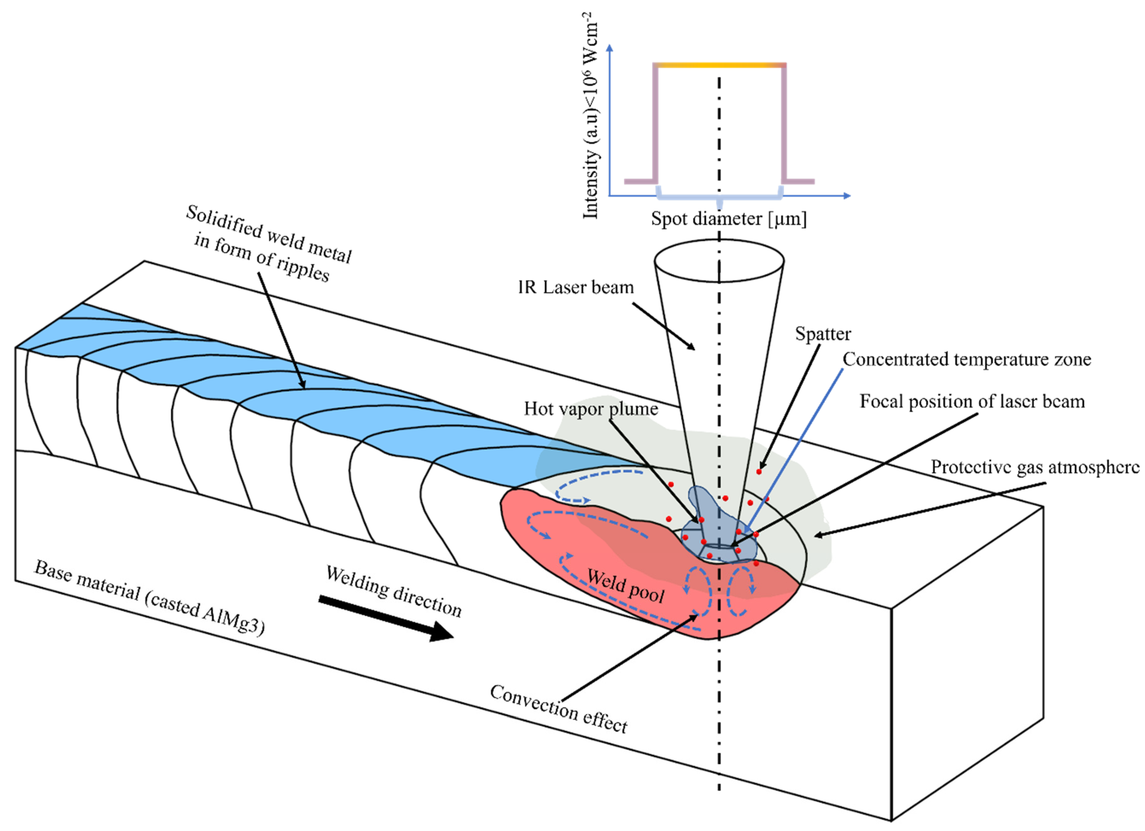
In this manuscript, a disk IR laser has been utilized to conduct laser welding in conduction mode of AlMg3 casted alloy. During laser welding, a high-speed imaging camera was used to record hot vapor plume formation. Based on the area and the intensity of the plume coupled with metallographic cross-section analyses, features have been identified that can indicate porosity formation.
2. Materials and Methods
In the study, commercial casted AlMg3 alloy material was used in conduction mode laser welding experiments to determine the optimal parameters for defects-free seams. The material was cut in form of prismatic samples with dimensions: length = 20 mm, width = 20 mm and height = 5 mm. Before experiments, each specimen was cleaned with ethylic alcohol and distilled water to remove the impurities and grease that might affect the surface laser absorption.
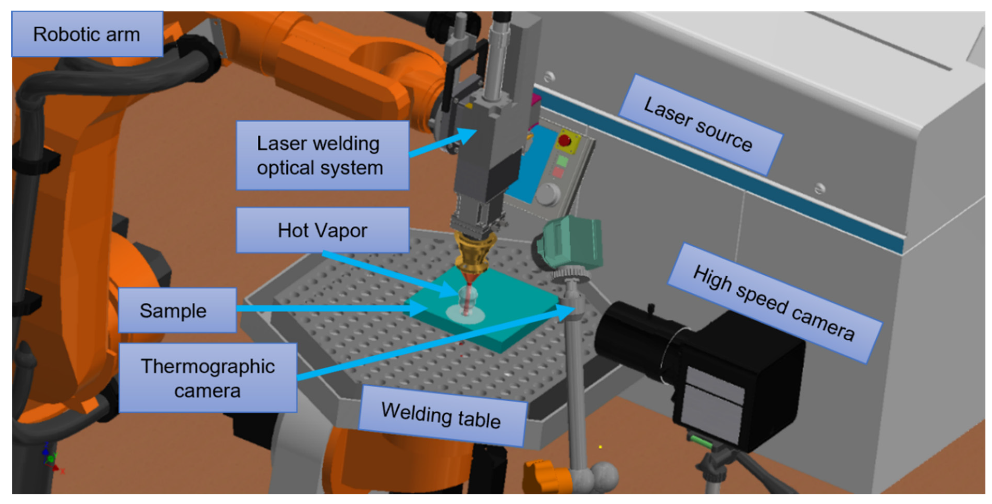
The samples were irradiated on the top using the laser beam generated by a continuous Yb: YAG laser source TruDisk 3001 (Trumpf, Ditzingen, Germany), emitting at 1030 nm wavelength. The laser radiation was transported through optical fibers to a robotic arm, Kr30HA (Kuka, Augsburg, Germany), with 6-degrees of freedom. An optical system dedicated to laser welding, consisting of a collimator, guiding mirrors, and a lens with a focal length of 200 mm (Trumpf, Ditzingen, Germany), was assembled on the robot. The laser spot diameter was 800 µm and was measured from the fingerprint left on an Al control plate coated with black color paint, when irradiated with a 50 ms pulse of 300 W power. The experiments were conducted in a protective argon (Ar) atmosphere, which was delivered via a nozzle placed in the vicinity of the irradiated zone. A range of gas flow rates between 2 and 30 l/min was used for the experiments.
During laser welding experiments, the variations of hot vapor plume were recorded using a high-speed complementary metal-oxide-semiconductor (CMOS) camera (mini AX100, Photron, Tokyo, Japan) with an image resolution of 384 × 384 pixels. To monitor the dynamic behavior of the plume through a 50 mm focal length Nikkon objective, the camera was mounted horizontally, parallel to the sample surface, as shown in
Figure 1. Frame rates (fps), in the range 20,000–30,000 fps were selected, and the exposure time was set at 1/fps. Furthermore, to record the images of the radiant plume in the visible and near-infrared range that can be captured by the high-speed camera, a neutral density (ND) filter was mounted on the camera lens to reduce the plume brightness. The weld pool generated in laser-welding process was monitored using a thermographic camera TIM M-01 (Micro-Epsilon, Ortenburg, Germany) with sensitivity in the range of 500–1800 °C. The thermal distribution of the weld pool was captured using a resolution of 382 × 288 pixels and a frequency of 80 Hz. The camera was placed at 60 cm away from the sample, thus covering a 25 × 15 cm
2 monitoring area. To overcome the inhomogeneous behavior of the material due to heat accumulation during irradiation, the welding experiments were conducted using two successive passes of the laser beam back and forth over the same weld seam.
To correlate the physical meaning of the acquired images with the defects from the seam, the hot vapor plume was recorded with the high-speed imaging camera and different ND filters to determine the shape and size of the hot vapor plume during laser welding. The characteristic values of the hot vapor were determined from the captured images using open-source software, ImageJ (LOCI, University of Wisconsin, Madison, WI, USA). The original images were processed via cropping, binarization and edge detection. After this process, the plume height and area were extracted to characterize the hot vapor plume features and compare the plumes in different zones of the weld seam. After interpreting the hot vapor plume characteristics, where the area, the mean and core values of the intensity in case of a dynamic system were extracted, a numerical analysis was conducted to identify a correlation between pores formation and hot vapor plume variations.
Figure 1 shows the schematic of the experimental set-up applied to perform laser welding.
After performing the welding experiments, all the samples were subjected to metallographic and optical microscopy characterizations. For this purpose, a Brilliant 200 cutting machine (ATM, Mammelzen, Germany), with a disc rotation speed of 2850 rpm, was used. The sliced specimens were then embedded in Bakelite using a hot-pressing machine with 30 mm diameter, 50 bar pressure and 200 °C temperature, employing an Opal 410 device (ATM, Mammelzen, Germany). Finally, the specimens were polished to mirror level using a Saphir 520 machine (ATM, Mammelzen, Germany), equipped with an automized mounting head for fixation and rotation of incorporated samples. After metallography, an optical microscope DM4000 B LED (Leica, Wetzlar, Germany) was used to visualize the structure of samples and the cross-sections of the welds.
Based on these cross-sections′ images, the pore locations were determined precisely and the hot vapor plumes corresponding to those areas were used for comparisons with plumes recorded in non-porous areas.
This paper compiles efforts to observe a correlation between the irradiated area and hot vapor plume intensity to identify early appearance of pores. Thus, the combination of the described in situ monitoring methods could allow the development of a future real-time quality management system based on advanced data processing. With this method, it will be possible to set a range of allowed porosity according to welding standards for various alloys and it will be possible to determine if these limits are surpassed using the proposed non-destructive technique.
3. Results
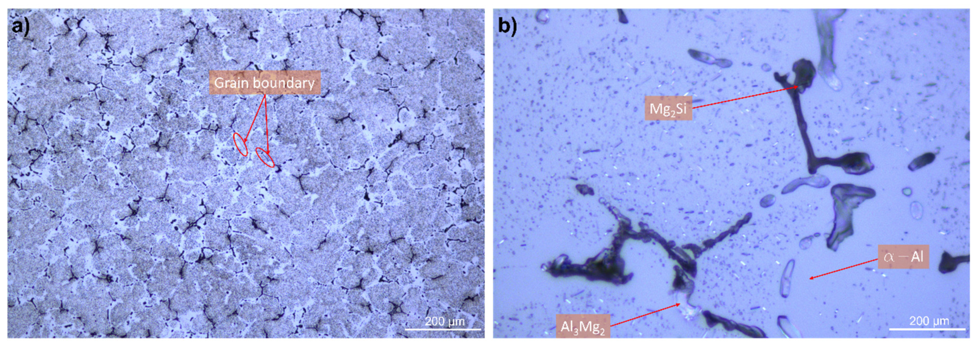
Before laser processing, an AlMg3 sample was polished and etched with Kroll’s reagent to identify the intermetallic phases.
Figure 2a,b present optical images of the polished AlMg3 specimen. It can be observed that the microstructure is coarse-grained, with an average grain size of approximately 290 µm. In
Figure 2b, the lighter phase is α-Al, that represents the primary phase, separated by an eutectic mixture located in the inter-dendritic spaces [
44]. Furthermore, in between the light dendrites of the preliminary aluminum phase, darker phase particles were identified in the form of uniformly distributed small eutectic clusters. The eutectics follow the aluminum phase transformations diagram—β-Al
3Mg
2 and the darker one is the silicon-containing phase—Mg
2Si [
44].
To identify the optimum laser welding operating parameters, a hit and trial strategy was implemented implying several experiments. To determine the optimum conditions, two objectives were defined: (a) to obtain a penetration depth as high as possible and (b) lack of defects. These optimum parameters for laser welding of AlMg3 alloy are summarized in
Table 1.
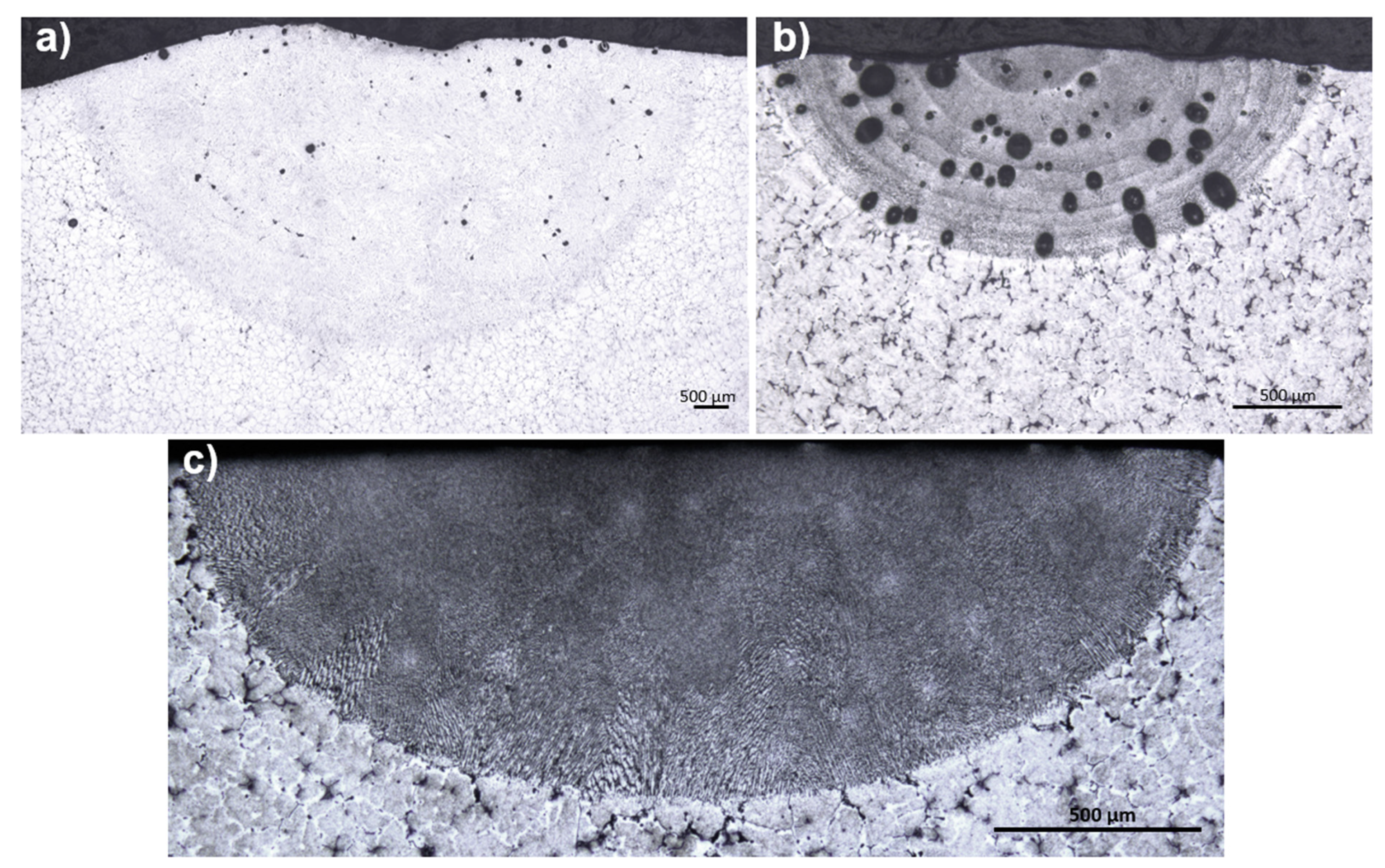
To increase the laser absorption and reduce the possibility of contaminating the resulted weld seam with oxide particles, the AlMg3 sample′s surface was roughened by grinding with a P600 abrasive paper. Moreover, a series of experiments with the maximum laser power of 3000 W was conducted, in which the laser beam was tilted with respect to the sample’s surface from 85 to 5° with a step of 5°. The maximum penetration depth equal to 4.5 mm was observed in the case of a 40° tilting angle (
Figure 3a) compared to a 0° tilting angle (800 µm depth) (
Figure 3b). Tests were also conducted with defocused laser beams. The defocus was varied between −4 and +4 mm, with 1 mm steps. The maximum penetration depth of 4.5 mm was obtained for a defocusing of −4 mm and 12 consecutive passes over the same weld line.
However, in this set of experimental conditions, porosity could not be eliminated. It is worth mentioning that spherical pores were formed while working in Ar (1–2 bar pressure), as shown in
Figure 3b. When the Ar pressure increased from 2 to 5 bar, the size of the pores was reduced, and polyhedral-shaped pores were observed besides the spherical ones. The explanation is that the Ar pressure was initially insufficient to ensure a proper shroud and air that containing water vapors penetrated in the vicinity of the processing area. As the liquid Al is highly absorbent to gaseous hydrogen (while solid Al expels it) gas bubbles remained captive in the bulk sample after solidification. When increasing the Ar pressure up to 5 bar, air could not enter into the processing area. However, new elongated pores emerged due to internal stresses generated by the rapid heating and cooling of the given alloy. This process became iterative with the number of laser beam passes, resulting in minor defects. In this study, the complete elimination of the pores was not achieved. Furthermore, more than 1 mm penetration depth could not be achieved. It has been found that the number of laser beam passes directly correlates with the penetration depth.
The sudden heating and cooling of the alloy by repeated passes of the laser beam caused internal stresses which generated small defects. We have not identified a successful experimental regime able to completely remove the porosity, while also obtaining penetration depths higher than 1 mm. However, in order to eliminate the porosity from the internal structure of the seam we reduced the number of passes. This leads to a small depth penetration, ~800 µm (
Figure 3c).
The high-speed imaging camera monitored the process to elucidate the differences in welding behavior of the samples depending on the experimental conditions.
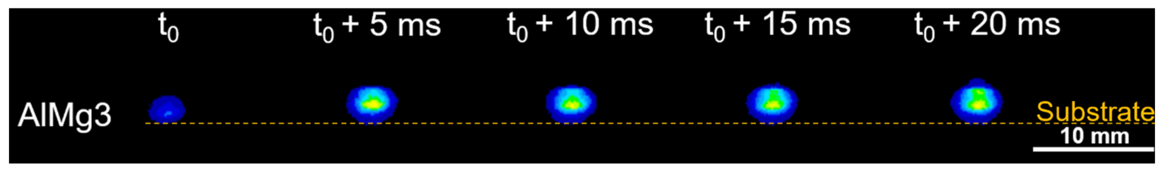
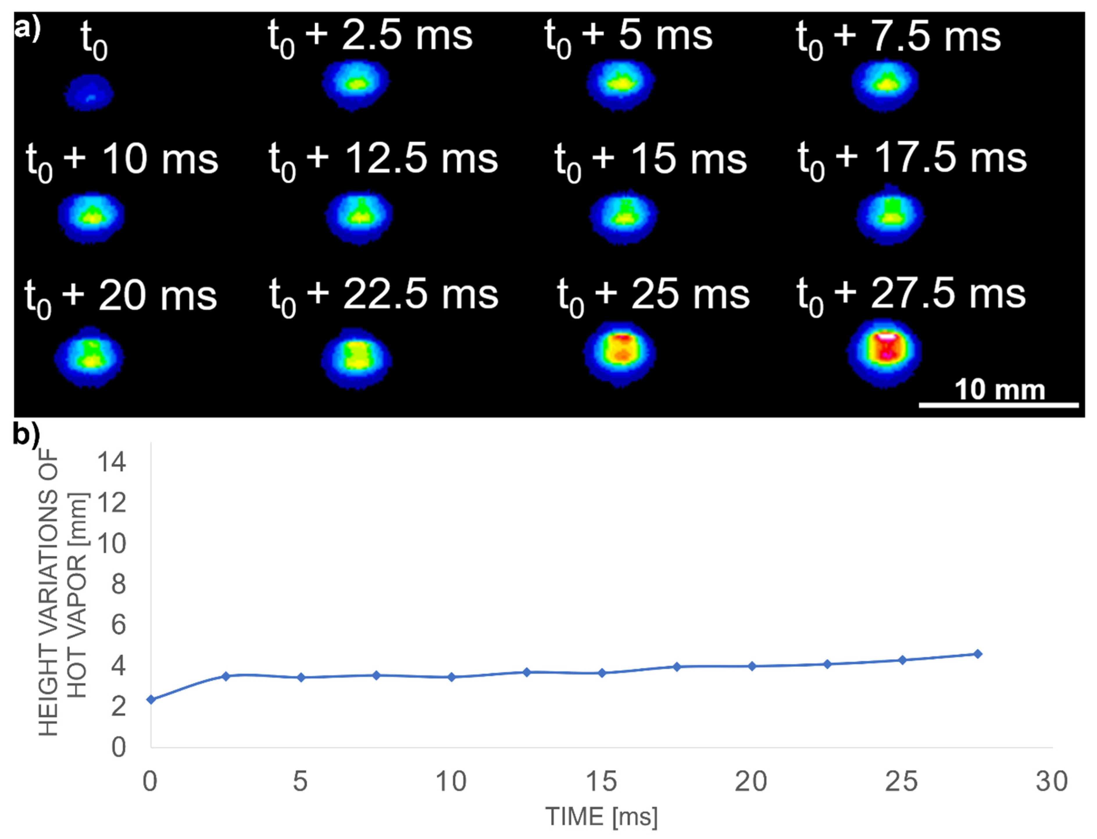
Figure 4 shows the hot vapor plume expansion using false colors in the case of AlMg3 alloy using optimal processing conditions (
Table 1). The time
t0 was selected, which is defined as the time when the first glimpses of hot vapor emission appear. For validating the stability, shots were taken at the same intervals after the hot vapor plume ignition. In this case, the hot vapor plume attained the maximum height and width after ~20 ms. The maximum plume height was of 4.6 mm.
Figure 5a,b reveal the evolution of the hot vapor plume height in an interval of 27.5 ms for AlMg3 irradiated in the optimal experimental conditions. The substrate was, in all cases, on the bottom part of
Figure 5a, the plume evolving on the orthogonal direction in respect to the substrate (z axis). It can be observed that the plume was stable with a mean value of 3.7 ± 1 mm. The expansion speed of the plume was 3.6 m/s in the case of AlMg3.
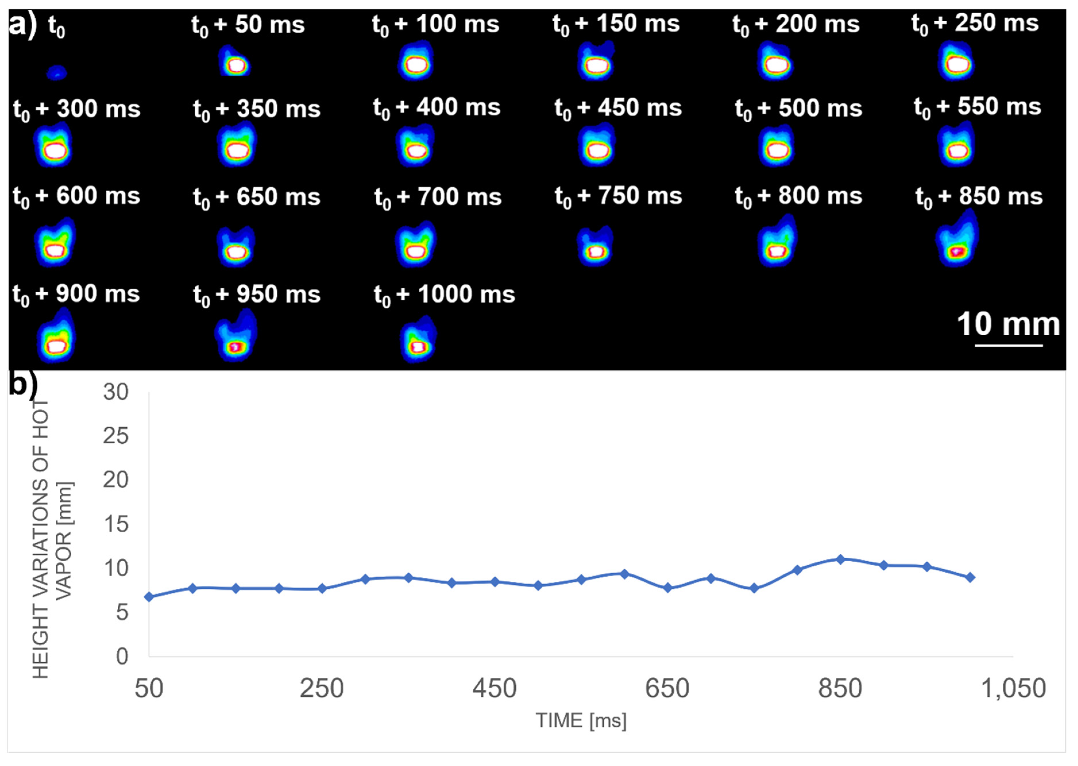
Figure 6 shows the height variation of the hot vapor plume after 50 ms with respect to the irradiation start time. In this case, the plume is also stable, with minor fluctuations between 5 and 10 mm in height with a mean value of 8.63 mm.
By setting the laser power at 3000 W and the robot translation speed to 0.02 m/s, the energy was sufficient to maintain the liquid phase for a long time to allow the pores to escape from the seam. Due to multiple passes on the same weld, porosity was drastically reduced by remelting the weld seam. In the opposite case, when a lower laser power was used for irradiation of the samples, the insufficient energy input resulted in a fast solidification of the weld pool that did not provide the necessary time for the pores to leave the liquid phase.
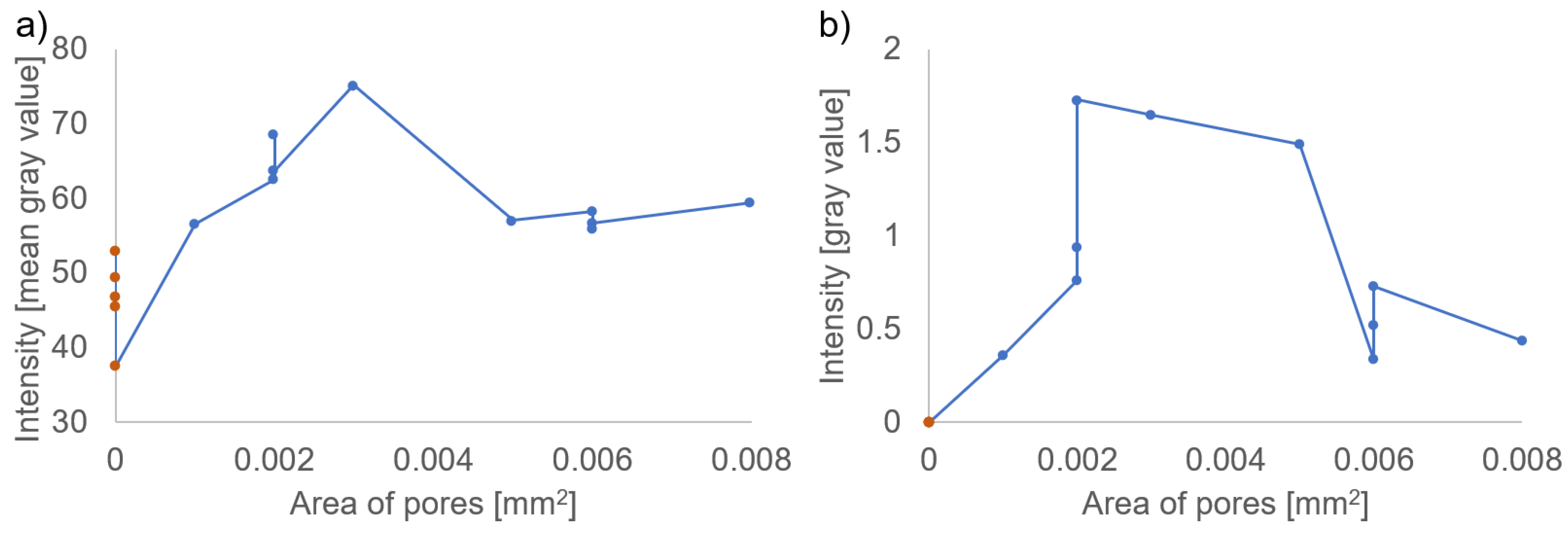
Figure 7 presents the corresponding hot vapor plume intensity values.
Figure 7a shows the intensity from the entire area of the hot vapor plume, and it was observed that when gray level value of 53 was surpassed, the pore appearance was inevitable. In
Figure 7b, the values for the high intensity area (above 255 gray value) appear only in the hot vapor plume corresponding to the zones with porosity.
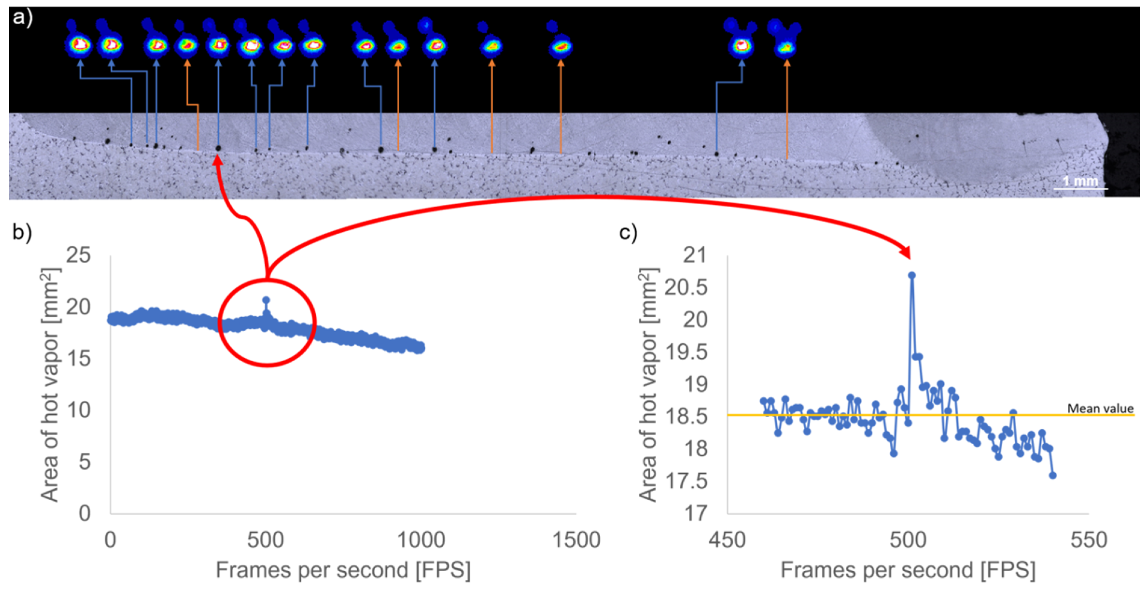
Figure 8a presents a correlation between hot vapor plume area variation and pores appearance in the weld seam. It can be seen that the areas with pores (blue arrows) showed higher hot vapor plume intensity compared to the area without defects (orange arrows).
Figure 8b and c show that the presence of a pore determines an increase of the plume area. In
Figure 8b, the variation of hot vapor plume area, before and after the zone with the defect, has been highlighted. It can be observed that when there is a pore in the weld, the hot vapor plume area increases. In
Figure 8c, a magnified view has been presented to highlight the peak value corresponding to the pore formation. The results reveal that the area of the hot vapor plume increases by more than 18.5 ± 1 mm
2 in case of pore containing areas.
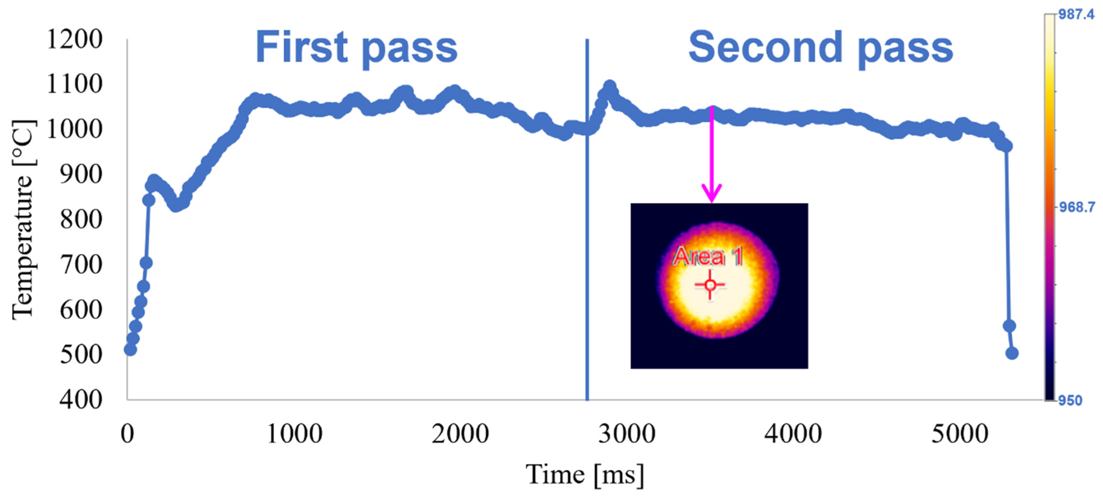
Figure 9 presents the temperature fluctuations within the liquid phase of weld pool for 2 laser beam passes. At the beginning of the process, the temperature grows up to 900 °C, probably due to a small stationary period of the robotic arm after the laser ignition. Following that, the temperature declined to 830 °C during the robot movement. During the second pass, a mean temperature of 1020 °C was reached. During the first laser beam pass, the fluctuations of the temperature values can be explained by the fact that the laser cannot deliver sufficient power to generate a stabilized weld pool. During the second pass, the absorption of the laser beam increases due to heat accumulation, resulting in thermal distribution steadiness that ultimately generates a stable weld pool necessary to achieve a smooth weld seam.
4. Discussion
As shown in the results section, the weld seam quality can be controlled by interpretation of optical signals that can identify the possible appearance of porosity.
For this type of material keyhole welding was not possible as it produced a high amount of spatter resulting in underfill and high porosity. Therefore, the irradiation regime was toned down in order to limit the liquid movement in the seam. We eliminated porosity, however, the penetrated depth was of 1 mm only.
Conduction laser welding described in this paper can be used in applications that requires smooth and rounded seam in order to exclude any additional finishing processes (
Figure 10). In conduction laser welding, energy is coupled into the workpiece exclusively through heat conduction via the surface of the sample. For this reason, the weld depth ranges from only a few tenths of a millimeter to approximately 1 mm. The increase coefficient of conductivity and the high reflectivity makes the aluminum alloys absorb only a small fraction of the incident radiation, hence limits the maximum weld depth penetration. The high thermal conductivity produces a rapid heat transfer through the surface sample, avoiding the high concentration of energy in the weld pool, thus limits the pore appearances by vaporization and finally, the lower viscosity of the welding pool restricts the expansion of the liquid phase before solidification. If the heat is not able to dissipate quickly enough, as in the 12 passes regime, the processing temperature rises above the vaporization temperature. Metal vapor forms, the welding depth increases sharply, and the process turns into deep penetration welding increasing the probability of pores appearance in the weld seam.
The use of conduction laser welding described in this paper shows a whole range of possibilities for advanced and critical joining applications using aluminum alloys. Laser conduction mode of welding was revealed to be applicable in cases where high quality and stable welds are required. Thus, in conduction mode is hardly seen any vaporization of elements of the alloy and defects such as porosity or excessive spatter are eliminated improving the overall aspect and characteristics of the weld seam. Larger beam diameter that is used in conduction mode allows a bigger fit up tolerance. Normally conduction mode is associated to the welding of aluminum, because it presents the advantages of low vaporization (which is one of the main causes of porosity) and the slow cooling rate that improves the weld seam geometry.
Using a combination of experimental conditions, the proposed objectives, including (a) penetration depth of more than 4 mm and (b) lack of defects, were obtained. It has been demonstrated that by using a 40° tilting angle, the highest penetration depth (4.5 mm) was achieved. A regime that achieved complete pores elimination after reducing the laser beam passes from 12 to 2 with penetration depth = 800 µm. Two types of pores geometries were identified:
(a) The accumulation of high energy density in the material can result in micro-explosions of vaporized material, leading to entrapped gases in the liquid phase. The temperature difference between the top and the bottom of the weld pool can produce localized turbulences and Marangoni convection effects that can disperse the pores in different directions along with the laser beam translation, as the liquid tries to flow in the opposite direction. The identified pores diameters are in the range of 35 to 100 µm and can be isolated in the seam or form clusters, thus producing cavities of various sizes and shapes. During welding with numerous passes, the interconnected pores network is generated by successive remelting and solidification of material based on the gas circulation within the melt pool. The relevant results are presented in
Figure 3a, where 12 passes were needed to obtain the seam. The depth penetration was observed to increase to almost 4.5 mm due to the high amount of energy density (~2000 kJ/cm
2). Furthermore, the reduction in the number of laser beam passes directly influenced the pores formation and penetration depth, as shown in
Figure 3c.
(b) Pores could be also generated by the entrapped gases from the gas shroud. In this case, the liquid phase of Al absorbs the H
2 from the atmosphere, while solid Al expels it and during rapid solidification of the material, gas bubbles remain trapped in the seam. Thus, pores with spherical shapes appeared in the weld structure and formed clusters after several passes. It is worth mentioning that a reduced amount of Ar-gas used to streamline the gas consumption resulted in the shrink of the shroud.
Figure 3a presents the formation of such pores. In this case, the solution to decrease the porosity was to increase the Ar-gas flow from 1 to 5 bar. However, after solidification, some pores remained in the structure due to vaporization of the molten material that occurred at high power laser welding. This problem cannot be eliminated by reducing the energy density, as the lower energetic conditions will not ensure welding with our initial specifications, thus leading to weld seam discontinuities.
Another cause of porosity can occur due to the pores already existing in the base material during casting. In this case, porosity was found to increase in the fusion zone based on the pores expansion and the reduction in the gas pressure inside the pores. This phenomenon occurs due to the heat generated in the fusion zone.
After material solidification following laser welding, the pores entrapment in a given material can serve as an arising stress point. It can result in cracks formation if the welded parts are subjected to mechanical loads. Therefore, the elimination of pores or their significant reduction is mandatory in achieving quality welds. To control the pores generation during the laser welding, the dynamics of the plumes have been monitored under different process parameters to determine a correlation between the optical signals and defects appearance. It has been determined that the variation in hot vapor plume intensity and area during laser welding can help identify the weld seam′s quality. Thus, the laser welding process can be monitored in real-time with an adequate and fast image analysis protocol to recognize the formation of pores during laser welding.
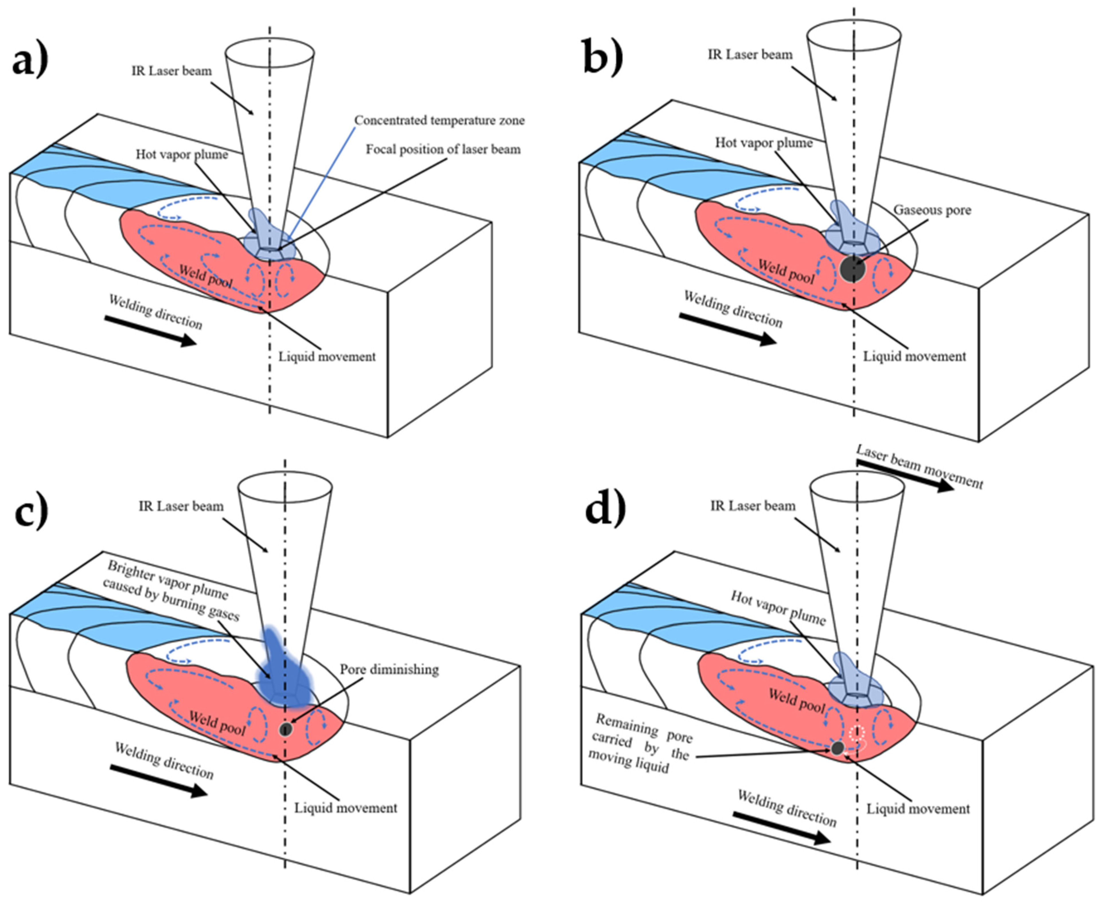
A possible explanation for the plume increased brightness when the laser beam passes through a pore could be the following: the moving laser beam pushes liquid in the back of the scanned area and the bottom liquid tends to move in a spiral motion (
Figure 11a). If a pore enters in contact with the laser beam, it is split, most of the gases being burned, resulting in supplemental heat in the plume (
Figure 11b), while the remaining unburned part of the initial pore (or the burned gases) form a smaller spherical pore (
Figure 11c). This pore is pushed by the moving liquid towards the bottom of the molten pool (
Figure 11d). The liquid metal solidifies very fast after the laser beam moves from that specific area and the pore doesn’t have the time to be expulsed from the weld, remaining trapped in the solidified metal.
A high-speed imaging camera is an excellent non-destructive method to analyze pores formation in the weld seam based on hot vapor plume variations analyses. The disadvantage compared to metallographic techniques is that in this case, the method is limited to identifying pores′ positioning in the weld seam and cannot provide quantitative data for their size. In the current scenario, the high-speed images showed that the plumes fluctuated throughout the entire process but with small oscillations in the range of 5–10 mm in height with a mean value of 8.63 mm. Due to the relatively steady characteristics of the hot vapor plume during AlMg3 alloy welding, it was easy to observe if the values for a given area increased in a local zone or concentrated on a specific region. This technique is useful for the welding process to reduce the analysis time from days or even weeks to minutes for samples preparations and analyses compared to metallographic methods. Another advantage is identifying pores formation in real-time during the laser welding process. This can provide essential data about the weld seams’ quality without any mechanical interventions.
In case of the hot vapor plume, two main regions were of interest: (a) high-density hot vapor region (core) located at the center and (b) external region-diffusion hot vapor placed around the first region. The variations in plume area showed that if a threshold value of 18.5 ± 1 mm
2 is exceeded, a probability of pore formation strongly exists. Not only the site but also the fluctuation of intensity can provide information about porosity. As shown in
Figure 8a, the vapor’s core, in the case of an area having porosity, is brighter than the areas without pores. This behavior can be observed along the weld seam without exceptions. From these results, one may conclude that the excessive brightness of hot vapor plume in the core region can be associated with pore appearance in the weld seam. In our experimental conditions, if the core has spots with the value of 255 on the grayscale, the pores appearance in the welds is inevitable.
Author Contributions
Conceptualization, S.M. and A.C.P.; methodology, S.M., D.C. and A.C.P.; software, S.M.; validation, S.M., D.C., M.A.M. and A.C.P.; formal analysis, S.M. and A.C.P.; investigation, S.M.; resources, D.C. and A.C.P.; data curation, S.M., D.C. and A.C.P.; writing—original draft preparation, S.M., D.C., M.A.M., L.D., M.L. and A.C.P.; writing—review and editing, S.M., D.C., M.A.M., L.D., M.L. and A.C.P.; supervision, M.L. and A.C.P.; project administration, D.C. and A.C.P.; funding acquisition, A.C.P. All authors have read and agreed to the published version of the manuscript.
Funding
S.M., D.C. and A.C.P. has received the funding of the PCE57/2021, PED514/2020 and POC-G Contract no. 135/2016 projects. D.C., A.C.P. and L.D. acknowledges the support of the Romanian Ministry of Education and Research, under Romanian National Nucleu Program LAPLAS VI–contract no. 16N/2019. M.A.M. has received financial support from the European Union’s Horizon 2020 (H2020) research and innovation program under the Marie Skłodowska-Curie, grant agreement No. 764935.
Data Availability Statement
Not applicable.
Acknowledgments
The authors acknowledge the PCE57/2021 and PED514/2020 projects, Romanian Ministry of Education and Research, under Romanian National Nucleu Program LAPLAS VI–contract no. 16N/2019, POC-G Contract no. 135/2016 and the European Union’s Horizon 2020 (H2020) research and innovation program under the Marie Skłodowska-Curie, grant agreement No. 764935.
Conflicts of Interest
The authors declare no conflict of interest.
References
- Singh, A.K.; Dey, V.; Rai, R.N. Techniques to improveweld penetration in TIG welding (A review). Mater. Today Proc. 2017, 4, 1252–1259. [Google Scholar] [CrossRef]
- Agrawal, N.; Thakur, M.; Raj, J.; Baghel, A. A Review on TIG/MIG Welded Joints. IJSTE-Int. J. Sci. Technol. Eng 2017, 4, 65–71. [Google Scholar]
- Wang, P.; Chen, X.; Pan, Q.; Madigan, B.; Long, J. Laser welding dissimilar materials of aluminum to steel: An overview. Int. J. Adv. Manuf. Technol. 2016, 87, 3081–3090. [Google Scholar] [CrossRef]
- Naeem, M. Laser Processing of Reflective Materials. Laser Tech. J. 2013, 10, 18–20. [Google Scholar] [CrossRef]
- Dudin, M.N.; Voykova, N.A.; Frolova, E.E.; Artemieva, J.A.; Rusakova, E.P.; Abashidze, A.H. Modern trends and challenges of development of global aluminum industry. Metalurgija 2017, 56, 255–258. [Google Scholar]
- Staley, J.T.; Lege, D.J. Advances in aluminium alloy products for structural applications in transportation. Le J. de Phys. IV 1993, 3, C7–C179. [Google Scholar] [CrossRef]
- Mazzolani, F.M. Structural Applications of Aluminium in Civil Engineering. Struct. Eng. Int. 2006, 16, 280–285. [Google Scholar] [CrossRef]
- Wallerstein, D.; Salminen, A.; Lusquiños, F.; Comesaña, R.; García, J.; Rodríguez, A.; Badaoui, A.; Pou, J. Recent Developments in Laser Welding of Aluminum Alloys to Steel. Metals 2021, 11, 622. [Google Scholar] [CrossRef]
- Ashkenazi, D. How aluminum changed the world: A metallurgical revolution through technological and cultural perspectives. Technol. Forecast. Soc. Chang. 2019, 143, 101–113. [Google Scholar] [CrossRef]
- Anyasodor, G.; Koroschetz, C. Industrial based volume manufacturing of lightweight aluminium alloy panel components with high-strength and complex-shape for car body and chassis structures. J. Phys. Conf. Ser. 2017, 896, 12093. [Google Scholar] [CrossRef] [Green Version]
- Hirsch, J. Aluminium in Innovative Light-Weight Car Design. Mater. Trans. 2011, 52, 818–824. [Google Scholar] [CrossRef] [Green Version]
- Gupta, S.; Singh, D.; Yadav, A.; Jain, S.; Pratap, B. A comparative study of 5083 aluminium alloy and 316L stainless steel for shipbuilding material. Mater. Today Proc. 2020, 28, 2358–2363. [Google Scholar] [CrossRef]
- Ren, H.; Ma, K.; Li, C.; Zhang, Z.; Xu, W.; Feng, G. Design Analysis and Fatigue Testing of the Typical Structural Details of Aluminium Ships. In Proceedings of the Volume 11B: Honoring Symposium for Professor Carlos Guedes Soares on Marine Technology and Ocean Engineering, Madrid, Spain, 17–22 June 2018. [Google Scholar]
- Moreto, J.A.; Rossino, L.S.; Filho, W.W.B.; Marino, C.; Ferreira, M.D.C.; Taryba, M.; Fernandes, J.C.S. On the Global and Localised Corrosion Behaviour of the AA2524-T3 Aluminium Alloy Used as Aircraft Fuselage Skin. Mater. Res. 2019, 22. [Google Scholar] [CrossRef] [Green Version]
- Tiryakioğlu, M. Solubility of hydrogen in liquid aluminium: Reanalysis of available data. Int. J. Cast Met. Res. 2019, 32, 315–318. [Google Scholar] [CrossRef]
- Tiryakioğlu, M. The Effect of Hydrogen on Pore Formation in Aluminum Alloy Castings: Myth Versus Reality. Metals 2020, 10, 368. [Google Scholar] [CrossRef] [Green Version]
- Zhao, H.; White, D.R.; DebRoy, T. Current issues and problems in laser welding of automotive aluminium alloys. Int. Mater. Rev. 1999, 44, 238–266. [Google Scholar] [CrossRef]
- Popescu, A.C.; Delval, C.; Leparoux, M. Control of Porosity and Spatter in Laser Welding of Thick AlMg5 Parts Using High-Speed Imaging and Optical Microscopy. Metals 2017, 7, 452. [Google Scholar] [CrossRef] [Green Version]
- Popescu, A.; Delval, C.; Shadman, S.; Leparoux, M. Investigation and in situ removal of spatter generated during laser ablation of aluminium composites. Appl. Surf. Sci. 2016, 378, 102–113. [Google Scholar] [CrossRef]
- Xu, L.; Tang, X.; Zhang, R.; Lu, F.; Cui, H. Weld bead characteristics for full-penetration laser welding of aluminum alloy under electromagnetic field support. J. Mater. Process. Technol. 2021, 288, 116896. [Google Scholar] [CrossRef]
- Bachmann, M.; Avilov, V.; Gumenyuk, A.; Rethmeier, M. Experimental and Numerical Investigation of an Electromagnetic Weld Pool Control for Laser Beam Welding. Phys. Procedia 2014, 56, 515–524. [Google Scholar] [CrossRef] [Green Version]
- Zhan, X.; Zhao, Y.; Liu, Z.; Gao, Q.; Bu, H. Microstructure and porosity characteristics of 5A06 aluminum alloy joints using laser-MIG hybrid welding. J. Manuf. Process. 2018, 35, 437–445. [Google Scholar] [CrossRef]
- Tao, W.; Yang, S. Weld zone porosity elimination process in remote laser welding of AA5182-O aluminum alloy lap-joints. J. Mater. Process. Technol. 2020, 286, 116826. [Google Scholar] [CrossRef]
- You, D.Y.; Gao, X.D.; Katayama, S. Review of laser welding monitoring. Sci. Technol. Weld. Join. 2014, 19, 181–201. [Google Scholar] [CrossRef]
- Shevchik, S.; Le-Quang, T.; Meylan, B.; Farahani, F.V.; Olbinado, M.P.; Rack, A.; Masinelli, G.; Leinenbach, C.; Wasmer, K. Supervised deep learning for real-time quality monitoring of laser welding with X-ray radiographic guidance. Sci. Rep. 2020, 10, 3389. [Google Scholar] [CrossRef] [PubMed] [Green Version]
- Ma, D.; Shu, L.; Zhou, Q.; Cao, S.; Jiang, P. Online porosity defect detection based on convolutional neural network for Al alloy laser welding. J. Phys. Conf. Ser. 2021, 1884, 012008. [Google Scholar] [CrossRef]
- Bardin, F.; Cobo, A.; Lopez-Higuera, J.M.; Collin, O.; Aubry, P.; Dubois, T.; Högström, M.; Nylen, P.; Jonsson, P.; Jones, J.D.C.; et al. Optical techniques for real-time penetration monitoring for laser welding. Appl. Opt. 2005, 44, 3869–3876. [Google Scholar] [CrossRef] [Green Version]
- Zhang, B.; Hong, K.-M.; Shin, Y.C. Deep-learning-based porosity monitoring of laser welding process. Manuf. Lett. 2020, 23, 62–66. [Google Scholar] [CrossRef]
- Yusof, M.; Ishak, M.; Ghazali, M. Weld depth estimation during pulse mode laser welding process by the analysis of the acquired sound using feature extraction analysis and artificial neural network. J. Manuf. Process. 2021, 63, 163–178. [Google Scholar] [CrossRef]
- Lu, M.-C.; Chiou, S.-J.; Kuo, B.-S.; Chen, M.-Z. Analysis of Acoustic Emission (AE) Signals for Quality Monitoring of Laser Lap Microwelding. Appl. Sci. 2021, 11, 7045. [Google Scholar] [CrossRef]
- Cai, W.; Wang, J.; Jiang, P.; Cao, L.; Mi, G.; Zhou, Q. Application of sensing techniques and artificial intelligence-based methods to laser welding real-time monitoring: A critical review of recent literature. J. Manuf. Syst. 2020, 57, 1–18. [Google Scholar] [CrossRef]
- Xiao, X.; Liu, X.; Cheng, M.; Song, L. Towards monitoring laser welding process via a coaxial pyrometer. J. Mater. Process. Technol. 2020, 277, 116409. [Google Scholar] [CrossRef]
- Sibillano, T.; Ancona, A.; Berardi, V.; Lugarà, P.M. A Real-Time Spectroscopic Sensor for Monitoring Laser Welding Processes. Sensors 2009, 9, 3376–3385. [Google Scholar] [CrossRef] [PubMed]
- Kos, M.; Arko, E.; Kosler, H.; Jezeršek, M. Penetration-depth control in a remote laser-welding system based on an optical triangulation loop. Opt. Lasers Eng. 2020, 139, 106464. [Google Scholar] [CrossRef]
- Gao, Y.; Zhong, P.; Tang, X.; Hu, H.; Xu, P. Feature Extraction of Laser Welding Pool Image and Application in Welding Quality Identification. IEEE Access 2021, 9, 120193–120202. [Google Scholar] [CrossRef]
- Wen, X.; Wu, D.; Zhang, P.; Liu, S.; Luo, Z.; Jia, Z.; Ye, X.; Shi, H.; Yu, Z. Influence mechanism of the keyhole behavior on penetration depth by in-situ monitoring in pulsed laser welding of aluminum alloy. Optik 2021, 246, 167812. [Google Scholar] [CrossRef]
- Hummel, M.; Külkens, M.; Schöler, C.; Schulz, W.; Gillner, A. In situ X-ray tomography investigations on laser welding of copper with 515 and 1030 nm laser beam sources. J. Manuf. Process. 2021, 67, 170–176. [Google Scholar] [CrossRef]
- Pang, S.; Chen, X.; Shao, X.; Gong, S.; Xiao, J. Dynamics of vapor plume in transient keyhole during laser welding of stainless steel: Local evaporation, plume swing and gas entrapment into porosity. Opt. Lasers Eng. 2016, 82, 28–40. [Google Scholar] [CrossRef]
- Chen, Q.; Tang, X.; Lu, F.; Luo, Y.; Cui, H. Study on the effect of laser-induced plasma plume on penetration in fiber laser welding under subatmospheric pressure. Int. J. Adv. Manuf. Technol. 2014, 78, 331–339. [Google Scholar] [CrossRef]
- Xu, J.; Rong, Y.; Huang, Y.; Wang, P.; Wang, C. Keyhole-induced porosity formation during laser welding. J. Mater. Process. Technol. 2018, 252, 720–727. [Google Scholar] [CrossRef]
- You, D.; Gao, X.; Katayama, S. Visual-based spatter detection during high-power disk laser welding. Opt. Lasers Eng. 2014, 54, 1–7. [Google Scholar] [CrossRef]
- Fan, H.; Tsai, H.; Na, S. Heat transfer and fluid flow in a partially or fully penetrated weld pool in gas tungsten arc welding. Int. J. Heat Mass Transf. 2001, 44, 417–428. [Google Scholar] [CrossRef]
- von Witzendorff, P.; Kaierle, S.; Suttmann, O.; Overmeyer, L. Using pulse shaping to control temporal strain development and solidification cracking in pulsed laser welding of 6082 aluminum alloys. J. Mater. Process. Technol. 2015, 225, 162–169. [Google Scholar] [CrossRef]
- Tański, T.; Snopiński, P.; Borek, W.; Snopińki, P. Strength and structure of AlMg3alloy after ECAP and post-ECAP processing. Mater. Manuf. Process. 2016, 32, 1368–1374. [Google Scholar] [CrossRef]
| Publisher’s Note: MDPI stays neutral with regard to jurisdictional claims in published maps and institutional affiliations. |
© 2021 by the authors. Licensee MDPI, Basel, Switzerland. This article is an open access article distributed under the terms and conditions of the Creative Commons Attribution (CC BY) license (https://creativecommons.org/licenses/by/4.0/).


 ,
, 


